CN102291925A - Plasma electric generation system - Google Patents
Plasma electric generation system Download PDFInfo
- Publication number
- CN102291925A CN102291925A CN2011102341168A CN201110234116A CN102291925A CN 102291925 A CN102291925 A CN 102291925A CN 2011102341168 A CN2011102341168 A CN 2011102341168A CN 201110234116 A CN201110234116 A CN 201110234116A CN 102291925 A CN102291925 A CN 102291925A
- Authority
- CN
- China
- Prior art keywords
- coil
- plasma
- ion
- magnetic field
- energy
- Prior art date
- Legal status (The legal status is an assumption and is not a legal conclusion. Google has not performed a legal analysis and makes no representation as to the accuracy of the status listed.)
- Pending
Links
Images


Classifications
-
- H—ELECTRICITY
- H01—ELECTRIC ELEMENTS
- H01J—ELECTRIC DISCHARGE TUBES OR DISCHARGE LAMPS
- H01J7/00—Details not provided for in the preceding groups and common to two or more basic types of discharge tubes or lamps
- H01J7/24—Cooling arrangements; Heating arrangements; Means for circulating gas or vapour within the discharge space
-
- G—PHYSICS
- G21—NUCLEAR PHYSICS; NUCLEAR ENGINEERING
- G21B—FUSION REACTORS
- G21B1/00—Thermonuclear fusion reactors
- G21B1/05—Thermonuclear fusion reactors with magnetic or electric plasma confinement
- G21B1/052—Thermonuclear fusion reactors with magnetic or electric plasma confinement reversed field configuration
-
- G—PHYSICS
- G21—NUCLEAR PHYSICS; NUCLEAR ENGINEERING
- G21B—FUSION REACTORS
- G21B1/00—Thermonuclear fusion reactors
-
- G—PHYSICS
- G21—NUCLEAR PHYSICS; NUCLEAR ENGINEERING
- G21B—FUSION REACTORS
- G21B1/00—Thermonuclear fusion reactors
- G21B1/05—Thermonuclear fusion reactors with magnetic or electric plasma confinement
-
- Y—GENERAL TAGGING OF NEW TECHNOLOGICAL DEVELOPMENTS; GENERAL TAGGING OF CROSS-SECTIONAL TECHNOLOGIES SPANNING OVER SEVERAL SECTIONS OF THE IPC; TECHNICAL SUBJECTS COVERED BY FORMER USPC CROSS-REFERENCE ART COLLECTIONS [XRACs] AND DIGESTS
- Y02—TECHNOLOGIES OR APPLICATIONS FOR MITIGATION OR ADAPTATION AGAINST CLIMATE CHANGE
- Y02E—REDUCTION OF GREENHOUSE GAS [GHG] EMISSIONS, RELATED TO ENERGY GENERATION, TRANSMISSION OR DISTRIBUTION
- Y02E30/00—Energy generation of nuclear origin
- Y02E30/10—Nuclear fusion reactors
Abstract
The invention relates to a plasma electric generation system. A system and apparatus for controlled fusion in a field reversed configuration (FRC) magnetic topology and conversion of fusion product energies directly to electric power. Preferably, plasma ions are magnetically confined in the FRC while plasma electrons are electrostatically confined in a deep energy well, created by tuning an externally applied magnetic field. In this configuration, ions and electrons may have adequate density and temperature so that upon collisions they are fused together by the nuclear force, thus forming fusion products that emerge in the form of an annular beam. Energy is removed from the fusion product ions as they spiral past electrodes of an inverse cyclotron converter. Advantageously, the fusion fuel plasmas that can be used with the present confinement and energy conversion system include advanced (aneutronic) fuels.
Description
The application is that application number is 200680007428.2, the applying date is on March 7th, 2006, denomination of invention is divided an application for the application of " plasma electric generation system ".
Technical field
Stripped physical field such as the present invention relates generally to, particularly be used for confined plasma make nuclear fusion energy become may be used for the method and apparatus that becomes electric energy from the power conversion of fusion products.
Background technology
Fusion is that two light nucleus are combined to form a process than heavy nucleus.Fusion process discharges huge energy with the form of the particle of rapid movement.So because atomic nucleus is that positively charged-to cause-have between them the static of repulsion be the Coulomb force owing to be included in wherein proton.For the nuclear of two fusions, this repulsive force potential barrier must be overcome.When two nuclears fully were close together, this situation took place, and this moment, short-range nuclear force became strong to being enough to overcome Coulomb force and fusion nucleus.Nuclear overcomes energy that coulomb barrier needs to be provided by their heat energy, and this heat energy must be very high.For example, if temperature is 10 at least
4EV magnitude-roughly corresponding 10
8Kelvin, fusion speed can be considerable.The speed of fusion reaction is the function of temperature, levies with the scale that is called reactivity.For example, the reactivity of D-T reaction has the very wide peak between 30 keV and 100 keV.
Typical fusion reaction comprises:

Wherein, D represents deuterium; T represents tritium; The expression helion; N represents neutron; P represents proton; He represents helium; B
11Expression boron-11.The kinetic energy of the numeral fusion products in the bracket in each equation.
Preceding two reaction-D-D and the D-T that lists above react-and be neutron, this means that most of energy of fusion products is to be carried by rapid neutron.The shortcoming of neutron reaction is: many problems are given birth in the miscarriage of (1) rapid neutron, comprise the structural failure of reactor wall and high-caliber radioactivity for most of manufactured materialss; And (2) become their energy of electricity collection by the thermal power transfer with rapid neutron, and this is efficient low-down (less than 30%).The advantage of neutron reaction is: (1) their reactivity peak is in low relatively temperature; And (2) they because the loss that causes of radiation is low relatively, because the atomic number of deuterium and tritium is 1.
Reaction-D-He in other two equations
3And p-B
11-be called high-rank fuel.Be not as producing rapid neutron in the neutron reaction, their fusion products are charged particles.An advantage of high-rank fuel is that they produce the neutron of much less, and therefore the shortcoming relevant with them not too arranged.At D-He
3Situation under, produce some rapid neutrons by secondary response, but these neutrons only account for about 10 of fusion products energy.P-B
11Reaction is no rapid neutron, though it produces some really by the neutron at a slow speed that secondary response causes, produces the problem of much less.Another advantage of high-rank fuel is that their fusion products comprise that its kinetic energy can be directly changed into the charged particle of electric energy.With suitable conversion process of energy, the energy of high-rank fuel fusion products can be collected with high efficiency, may surpass 90 percent.
High-rank fuel also has shortcoming.For example, the atomic number of high-rank fuel is higher (for He
3Be 2, and for B
11Be 5).Therefore, their radiation loss big than in neutron reaction.Also have, make the high-rank fuel fusion much more difficult.Their peak value reactivity appears at much higher temperature, and does not reach as the reactivity of D-T high.So cause the fusion reaction requirement with high-rank fuel: make them reach higher energy state, their reactivity is very large under this state.Therefore, must seal high-rank fuel (containment) long period, they can reach suitable fusion condition therebetween.
Be the off-period for plasma
, wherein, r is stripped sizes such as minimum, D is a diffusion coefficient.The classical value of diffusion coefficient is
, wherein,
 Be the ion radius of gyration, and

 It is the ion-electron collision time.Diffusion according to classical diffusion coefficient is called classical transport.The instable glass nurse of the short wavelength that results from (Bohm) diffusion coefficient is
 , wherein
It is the ion gyrofrequency.Diffusion according to this relation is called unusual migration.For the fusion condition,
, wherein
It is the ion gyrofrequency.Diffusion according to this relation is called unusual migration.For the fusion condition,
 10
8, unusual migration causes the off-period than classical transport much shorter.By the off-period of the plasma of giving determined number must be longer than the time of plasma nuclear fusion reaction requirement, this relation is determined must be much at fusion reactor ionic medium body.So, consider less initial plasma, the classical transport condition is better in fusion reactor.
10
8, unusual migration causes the off-period than classical transport much shorter.By the off-period of the plasma of giving determined number must be longer than the time of plasma nuclear fusion reaction requirement, this relation is determined must be much at fusion reactor ionic medium body.So, consider less initial plasma, the classical transport condition is better in fusion reactor.
In early stage experiment, observed with the plasma toroidal confinement
 Off-period.Be increased to off-period in nearest 40 years progress
 An existing fusion reactor notion is tokamak (Tokamat).In past 30 years, the effort of fusion concentrates on the tokamak reactor that utilizes D-T fuel.These effort reach the peak in " ITER (ITER) ".Experiment with regard to tokamak recently proposes classical transport
 Be possible, under the situation of classical transport, minimum plasma size can reduce to cm from rice.These experiments comprise injects high energy beam (50 to 100 keV), the temperature of heated by plasma to 10 to 30 keV.See W.Heidbrink and G.J.Sadler, 34 Nuclear Fusion(nuclear fusions) 535(1984).Observe in these experiments, when hot plasma continued unusual fast diffusion, the high energy beam ion slowed down and classical the diffusion.This reason is, the high energy beam ion has the big radius of gyration, therefore, to the wavelength shorter than the ion radius of gyration (
) fluctuation insensitive.Short wavelength's fluctuation meeting is averaged the cycle and offsets thus.Yet electronics has the much smaller radius of gyration, so they are to fluctuation and migration response abnormality.
Be possible, under the situation of classical transport, minimum plasma size can reduce to cm from rice.These experiments comprise injects high energy beam (50 to 100 keV), the temperature of heated by plasma to 10 to 30 keV.See W.Heidbrink and G.J.Sadler, 34 Nuclear Fusion(nuclear fusions) 535(1984).Observe in these experiments, when hot plasma continued unusual fast diffusion, the high energy beam ion slowed down and classical the diffusion.This reason is, the high energy beam ion has the big radius of gyration, therefore, to the wavelength shorter than the ion radius of gyration (
) fluctuation insensitive.Short wavelength's fluctuation meeting is averaged the cycle and offsets thus.Yet electronics has the much smaller radius of gyration, so they are to fluctuation and migration response abnormality.
Because unusual migration, the minimum dimension of plasma must be at least at 2.8 meters.Because this size, ITER is built to 30 meters high and 30 rice diameters.This is actual possible minimum D-T tokamak type reactor.For high-rank fuel, D-He for example
3And p-B
11, tokamak type reactor can be had to much bigger, and is much longer because the fuel ion has the time of nuclear reaction.Use the tokamak type reactor of D-T fuel that other problem is arranged, this problem is, most of energy of fusion products energy is carried by 14 MeV neutrons, this in nearly all construction material because neutron current causes radiation damage and induction reactive.In addition, their power conversion becomes electric energy must lean on thermal process, and conversion efficiency is not more than 30% like this.
The reactor configuration of another suggestion is the colliding beam reactor.In the colliding beam reactor, by some ion beam bombardment background plasmas.These bundles comprise the ion with energy more much bigger than hot plasma.It has been unpractical producing useful fusion reaction in such reactor, because background plasma is restrainted ion beam slowly down.For reducing this problem and the quantity maximum that makes nuclear reaction, various suggestions have been proposed.
For example, people's such as Jassby U.S. Patent No. 4065351 has disclosed the method that produces the adverse current colliding beam of deuterium and tritium in the toroidal confinement system.In people's such as Jassby U.S. Patent No. 4057462, inject electromagnetic energy and offset one the influence of body equilibrium plasma towing these ion nucleic.The toroidal confinement system is equal to tokamak.In the U.S. Patent No. 4894199 of Rostoker, inject in the reverse configuration on the spot and capture deuterium and tritium at the tokamak mirror with same average speed.In order to capture the independent purpose of bundle, low-density cold background plasma is arranged.They have Shu Yinwei high temperature and react, and mainly slow down by following the electronics that injects ion to cause.Electronics is heated by ion, and minimum slows down under this situation.
Yet the balance electric field does not cut any ice in any one in these devices.In addition, without any reducing or even the unusual intention of moving of consideration.
Other patents are considered the electrostatic confinement of ion and are considered the magnetic confinement of electronics in certain situation.These patents comprise the U.S. Patent No. 3258402 of Farnsworth and Farnsworth U.S. Patent No. 3386883(they disclosed the electrostatic confinement of ion and the inertial confinement of electronics), people's such as people's such as Hirsch U.S. Patent No. 3530036 and Hirsch U.S. Patent No. 3530497(and farnsworth are similar), its magnetic confinement of having disclosed the ion electrostatic confinement and having cut the electronics of reflecting wall with multipole meeting of the U.S. Patent No. 4233537(of Limpaecer) and the U.S. Patent No. 4826646(of Bussard and Limpaecer similar and comprise point cusp).Do not have one to consider the electrostatic confinement of electronics and the magnetic confinement of ion among these patents.Though existing many research topics about the ion electrostatic confinement do not have one successfully to set up the electrostatic field that requires when ion has the density of fusion reactor requirement among them.At last, do not have one field-reversed configuration magnetic topology is discussed among those patents of above-referenced.
Approximately nineteen sixty chances on field-reversed configuration (FRC) at " Naval Research Labratory " at azimuth constriction (theta pinch) experimental session.Fig. 3 and Fig. 5 illustrate the typical FRC topology of of internal magnetic field reverse directions, and Fig. 6 and Fig. 9 represent the racetrack among the FRC.About FRC, many projects have been subsidized in the U.S. and Japan.There is one piece about from the theory of the FRC research of nineteen sixty to 1988 year and the comprehensive survey paper of experiment.See M.Tusewski, 28 Nuclear Fusion(nuclear fusions) 2023(1988).White paper about FRC development has been narrated research in 1996 with to the suggestion of future studies.See people such as L.C.Steinhauer, 30 FusionTechnology(fusion technologies) 116(1996).So far, in the FRC experiment, form FRC with azimuth constriction method.The consequence of this formation method is, ion and electronics respectively carry half electric current, and this just causes insignificant electrostatic field in the plasma and no electrostatic field constrained.Ion and electronics in these FRC are sealed by magnetic.In nearly all FRC experiment, all suppose unusual migration.See for example beginning of 2072 pages of 1.5.2 joints of Tusewski paper.
So, the abnormality migration that expectation provides a kind of fusion system with closed system and energy conversion system, described closed system can significantly reduce or eliminate ion and electronics, this energy conversion system becomes electric energy to the power conversion of fusion products with high efficiency.
Summary of the invention
The present invention relates to a kind of system, this system helps the conversion to electrical power of controlled fusion in having the magnetic field of field-reversed topology and fusion products energy.The optimum system choosing that is called plasma electric power generation (PEG) system here comprises the fusion reactor of the closed system with the abnormality migration that trends towards significantly reducing or eliminating ion and electronics.In addition, the PEG system also comprises that directly the fusion products power conversion is become electric energy with high efficiency and the energy conversion system reactor coupling.
In one embodiment, the migration of the abnormality of ion and electronics all can significantly be reduced or eliminated.Can avoid the abnormality migration of ion by magnetic confinement ion in the magnetic field of reverse configuration on the scene (FRC).For electronics, produce the highfield of electronics electrostatic confinement in dark potential well by tuning externally-applied magnetic field, avoided the abnormality migration of energy.As a result, the fusion fuel plasma that can be used for this restraint device and technology is not limited to neutron fuel, and also advantageously comprising senior is non-neutron fuel.For non-neutron fuel, the fusion reaction energy almost completely is that charged particle is the form of energetic ion.These charged particles can be controlled in magnetic field, decide according to fuel, do not cause or cause hardly radioactivity.
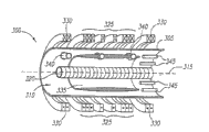
In a preferred embodiment, the plasma closed system of fusion reactor comprises the chamber, is used to be applied to basically along the magnetic field generator in the magnetic field on the direction of main shaft and the peripheral plasma floor that comprises the circulation ion beam.Peripheral plasma bundle layer with the form of track basically magnetic be enclosed in indoorly, and electronics remains essentially in the electrostatic energy trap.In a preferred embodiment, magnetic field generator comprises current coil.Preferably, magnetic field generator also is included near the mirror image coil (mirror coil) the end, chamber, and these coils are increased in the amplitude of the externally-applied magnetic field of end, chamber.System comprises that also one or several is used for the neutralization ion beam is injected into the bundle injector in magnetic field.In magnetic field, because the described bundle injection of power that magnetic field produces.In a preferred embodiment, system forms the magnetic field of the topology with field-reversed configuration.
In a further advantageous embodiment, provide a selectable chamber, this chamber prevents that the azimuth mirror image current from forming at the locular wall central area, and makes magnetic flux pass this chamber fast.Provide chamber structural strength and good vacuum performance, that mainly form to comprise, interrupt (break) along the axial dielectric in the locular wall of almost whole chamber length extension by stainless steel.Preferably, there are 3 apart from one another by the interruption of opening about 120 degree.These interruptions comprise groove or the slit that is formed in the wall.The insert that comprises insulating material (preferably ceramic etc.) is inserted in groove or the slit.In chamber interior, metal covering covers this insert.In outdoor, this insert is attached to preferably on the sealing plate that is formed into by glass fibre etc.Sealing plate forms the vacuum barrier by the O annular seal together with the stainless steel surfaces of locular wall.
In another preferred embodiment again, inductive plasma source can be installed in indoor, and comprises shock coil assembly (preferred single turn shock coil).It is preferably by high pressure (about 5-15 kV) power supply (not shown) feed.By direct gas feed the neutral gas as hydrogen (or other suitable gas fusion fuels) is incorporated in the source through Laval (Laval) nozzle.In case gas is discharged and it is distributed on the coil windings surface of shock coil itself from nozzle, winding just is energized.Ultrafast electric current and magnetic flux in the low inductance shock coil rise to the very high electric field that causes in the gas.This electric field causes that the plasma of puncture, ionization and formation is subsequently from the central authorities of shock coil table faced chamber or the injection of midplane.
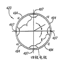
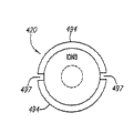
In another preferred embodiment, RF drives and to comprise and be positioned at four indoor utmost point cyclotrons, and it has 4 electrodes of gapped azimuthal symmetry each other.Four utmost point cyclotrons produce with the direction identical with the orientation speed of ion but with the potential wave of bigger speed rotation.Suitably the ion of speed can be captured in this ripple and be reflected periodically.This process increases the momentum and the energy of fuel ion, and this increases to be delivered to by collision and does not have captive fuel ion.
In another embodiment, the DIRECT ENERGY converting system is used for by the charged particle that slows down through electromagnetic field the kinetic energy of fusion products being directly changed into electric power.Advantageously, DIRECT ENERGY converting system of the present invention has the frequency of the fusion power output of changing about 5 MHz and efficient, particle energy tolerance and the electronic capability that phase place is mated the frequency of outside 60 Hz electrical networks.
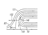
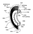
In a preferred embodiment, energy conversion system comprises the reversed cyclotron transducer (ICC) that combines with the opposite end of fusion reactor.ICC has the hollow circular cylinder shape geometry that the half-cylindrical electrode that equated by a plurality of (preferred 4 or more a plurality of) is formed, and is extended with little straight slot between the described electrode.At work, in the alternation mode vibration potential is added on the electrode.Electric field E in ICC has multi-polar structure, disappears on symmetry axis, increases with radius is linear, and peak value is located in the slit.
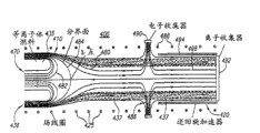
In addition, ICC comprises magnetic field generator, is used to be applied to even folk prescription on the direction opposite substantially with the externally-applied magnetic field of the closed system of fusion reactor to magnetic field.In the distal-most end from fusion reactor power core, ICC comprises ion trap.Between power core and ICC, be that the magnetic of symmetry can be cut, here, the magnetic field of closed system and the magnetic field of ICC merge.The circulating electron gatherer is placed in around magnetic can cut, and is coupled with ion trap.
In another preferred embodiment again, product nuclear and charging neutrality electronics are gushed out as the two ends of annular beam from the reactor capability core with a density, and owing to electronics and energy of ions difference, magnetic can be cut they is separated under this density.Electronics is following the magnetic line of force to electron collector, can cut and ion passes magnetic, and there, it is spiral path along ICC length basically that ion trajectory changes over.When the ion spiral when being connected to the electrode of resonant circuit, energy shifts out from them.The loss of vertical energy is near initial highest energy ion maximum of going in ring electrode, and described electrode place electric field is the strongest.
From the consideration of carrying out in conjunction with the accompanying drawings described below, it is obvious that other aspects of the present invention and characteristics will become.
Description of drawings
By way of example but be not the restriction, on accompanying drawing the explanation some preferred embodiments.Identical reference number means identical parts on the figure.
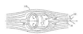
Fig. 1 represents the partial view of exemplary constraint chamber.
Fig. 2 A represents the partial view of another exemplary constraint chamber.
Fig. 2 B represents along the partial cross sectional views of the straight line 2B-2B on Fig. 2 A.
Fig. 2 C represents along the detailed view of the straight line 2C on Fig. 2 B.
Fig. 2 D represents along the partial cross sectional views of the straight line 2D-2D on Fig. 2 B.
Fig. 3 represents the magnetic field of FRC.
Fig. 4 A and 4B represent the diamagnetic and resistance magnetic direction among the FRC respectively.
Fig. 5 represents the colliding beam system.
Fig. 6 represents the rheotron track.
Fig. 7 A and 7B represent the direction of magnetic field among the FRC and gradient drift respectively.
Fig. 8 A and 8B represent respectively among the FRC electric field and
 The direction of drift.
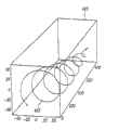
Fig. 9 A, 9B and 9C represent the ion drift track.
Figure 10 A and 10B are illustrated in the Lorentz force of the end of FRC.
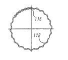
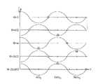
Figure 11 A and 11B the tuning of electric field in the beam system and current potential of representing to vibrate.
Figure 12 represents that maxwell distributes.
Figure 13 A and 13B represent because the transition from the rheotron track to drift orbit that angled ion-ion collision causes.
Figure 14 is illustrated in A, B, C and the D rheotron track when considering the collision of low-angle electron-ion.
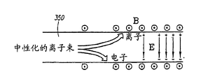
Neutral ion bundle when Figure 15 represents by electric polarization.
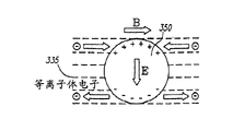
The front view of the neutral ion bundle when Figure 16 is illustrated in the contact plasma that retrains in the chamber.
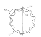
Figure 17 is the schematic end according to the constraint chamber of a preferred embodiment of starting process.
Figure 18 is the schematic end according to the constraint chamber of another preferred embodiment of starting process.
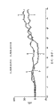
Figure 19 represents to show the trace that B form point that FRC forms is surveyed.
Figure 20 A represents to be installed in the view of indoor inductive plasma source.
Figure 20 B and 20C represent the partial view of inductive plasma source.
Figure 21 A and 21B represent the partial view of RF drive system.
Figure 21 C represents the schematic diagram of two utmost points and the configuration of four utmost points.
Figure 22 A represents the plasma electric generation system of part, and this system comprises the colliding beam fusion reactor with reversed cyclotron DIRECT ENERGY converter incorporates.
Figure 22 B represents the end-view of the reversed cyclotron transducer on Figure 19.
Figure 22 C is illustrated in the track of reversed cyclotron intermediate ion.
Figure 23 A represents the plasma electric generation system of part, and this system comprises the colliding beam fusion reactor that combines with the alternative embodiment of reversed cyclotron transducer.
The end-view of the reversed cyclotron transducer on Figure 23 B presentation graphs 20A.
Figure 24 A is illustrated in the racetrack of traditional cyclotron the inside.
Figure 24 B represents an oscillating electric field.
Figure 24 C represents the change energy of accelerated particle.
Figure 25 is illustrated in the azimuthal electric field at the place, slit between the electrode of ICC, and this electric field is experienced by the ion with angular speed.
Figure 26 represents to focus on quadrupole-doublet lens.
Figure 27 A and 27B represent the auxiliary magnetic field coil system.
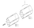
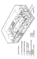
Figure 28 represents 100 MW reactors.
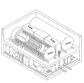
Figure 29 represents the support equipment of reactor.
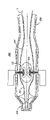
Figure 30 represents plasma thrust propulsion system.
Figure 31 represents the critical piece of plasma thruster propulsion system.
Figure 32 represents the calcspar of plasma thruster propulsion system.
Embodiment
As illustrated on scheming, plasma electric power generation of the present invention (PEG) optimum system choosing comprises the colliding beam fusion reactor (CBFR) with the coupling of DIRECT ENERGY converting system.As refer to that above-mentioned said, desirable fusion reactor has solved the two unusual migration problem of ion and electronics.The method utilization of the unusual migration problem of the solution of here finding has the closed system in magnetic field, and this magnetic field has field-reversed configuration (FRC).In this manner, that is, most of ions have big nonadiabatic track, and it is insensitive that they are fluctuateed to the short wavelength who causes the unusual migration of adiabatic ion, and the abnormality migration of ion is avoided by the magnetically confined among the FRC.Particularly, the zone that exists magnetic field to disappear among the FRC makes that to have a plasma that comprises most nonadiabatic ion possible.For electronics, avoid the abnormality migration of energy highfield to occur by tuning externally-applied magnetic field.Highfield constrains in electronics in the dark potential well statically.
Can be not limited to deuterium-deuterium for the fusion fuel plasma that this restraint device and technology are used as D-D() or D-T(deuterium-tritium) neutron fuel, but also advantageously comprise as D-He
3(deuterium-helium-3) or p-B
11Senior or the non-neutron fuel that (hydrogen-boron-11) is such.(about the discussion of high-rank fuel, seeing R. Feldbacher and M. Heindler, Nuclear Instruments and Method(nuclear instrument and method), Physics Research, A271(1988) jj-64(north Amsterdam, the Netherlands)).For so non-neutron fuel, the fusion reaction energy almost completely is that charged particle is the form of energetic ion.These charged particles can be controlled in magnetic field, and depend on fuel, cause radioactivity hardly.D-He
3Reaction produces a H ion and a He who has 18.2 MeV energy
4Ion, and p-B
11Reaction produces 3 He
4Ion and 8.7 MeV energy.For example, according to the theoretical modelling for the fusion facility that utilizes non-neutron fuel, the output energy conversion efficiency is can be according to appointment 90% high like that, as K.Yoshikawa, K. Noma and Y. Yamamoto at fusion technology, 19,870(1991) described in.Such efficient improves the prospect of non-neutron fuel aspect scalable (1-1000 MW), small-sized, configuration cheaply significantly.
The charged particle of fusion products that in DIRECT ENERGY transfer process of the present invention, can slow down, and can be directly changed into electric energy to their kinetic energy.Advantageously, DIRECT ENERGY converting system of the present invention has the frequency of fusion power output of about 5 MHz of conversion and phase place with the frequency of mating outside 60 Hz electrical networks and efficient, particle energy tolerance and the electronic capability of phase place.
The fusion closed system
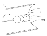
Fig. 1 explanation is according to the preferred embodiment of closed system 300 of the present invention.Closed system 300 comprises locular wall 305, wherein defines constraint chamber 310.Preferably, constraint chamber 310 is columniform in shape, has the main shaft 315 at 310 centers along the chamber.For this closed system 300 is applied to fusion reactor, be necessary in the chamber that vacuum is set up in 310 the insides or near vacuum.Concentric with main shaft 315 is rheotron flux coil (flux coil) 320, is positioned within the chamber 310.Rheotron flux coil 320 comprises the live flow medium that is suitable for around the long loop guide current, and as shown, this medium preferably includes the also winding of a plurality of independent coils, and most preferably, the also winding of about 4 independent coils is to form long loop.Those skilled in the art can understand, the electric current by rheotron coil 320 will produce magnetic field for 320 li at the rheotron coil, and this magnetic field is basically on the direction of main shaft 315.
Outside around locular wall 305 is an external coil 325.External coil 325 produces constant relatively magnetic field, and this magnetic field has basically the magnetic flux parallel with main shaft 315.This magnetic field is azimuthal symmetry.The magnetic field that is caused by external coil 325 is constant and is parallel approximate with main shaft 315, is the most correct away from 310 ends, chamber.Every end of 310 is a mirror coil 330 in the chamber.Mirror coil 330 be suitable for every end in the chamber 310 li magnetic fields that produce to increase, so at every end magnetic line of force (seeing Fig. 3 and 5) that curves inwardly.As explained above, this of the magnetic line of force curves inwardly and helps, and leaves end (it can flee from closed system 300 there) by promoting plasma 335, and it is enclosed in the enclosed area in the general chamber 310 between mirror coil 330.To the whole bag of tricks, comprise that the winding number, the increase that increase in the mirror coil 330 overlap by the electric current of mirror coil 330 or with external coil 325 and mirror coil 330 with known in the art, mirror coil 330 shells are suitable for producing in the end magnetic field of increase.
Be explained in more detail as following, the circulation plasma beam 335 that comprises charged particle can be enclosed in the chamber 310 by the Lorentz force that cause in the magnetic field that external coil 325 causes.Like this, the ion in the plasma beam 335 is enclosed in around on the big rheotron track of the magnetic flux line of external coil 325 by magnetic, and this magnetic flux line is parallel with main shaft 315.310 li also provide one or several bundle injection port 340 in the chamber, are used for plasma ion is added to circulation plasma beam 335.In a preferred embodiment, injection port 340 is suitable for promptly centering on zero-potential surface described below injecting ion beam from main shaft 315 approximately identical radial positions at described position circulation around circuit plasma beam 335().In addition, injection port 340 is suitable for being tangential to the rheotron track of the plasma beam 335 that is closed and injects ion beam 350(and see Figure 17 on the direction of this track).
One or more background plasmas source 345 also is provided, is used for injecting non-energetic plasma cloud to the chamber 310.In a preferred embodiment, background plasma source 345 is suitable for the axle center guiding of plasma 335 to chamber 310.Having been found that such directing plasma helps to seal better causes highdensity plasma 335 in plasma 335 and the enclosed area in chamber 310.
Vacuum chamber
As mentioned above, for the application of the closed system of CBFR, be necessary to produce vacuum or near vacuum in the inside, chamber.Because the interaction (scattering, charge-exchange) between neutral particle and the plasma fuel always provides the energy loss passage, so key is the interior residue density of limited reactions pile room.In addition, the impurity that cause the very poor chamber of being taken out by vacuum may cause polluting side reaction during operation, and may be at the energy that during starts overruns, these residues because system has to burnout.
Realize that the vacuum of good level is usually directed to the use of stainless steel chamber and port and low out-gassed material.Under the situation of metal, good vacuum performance further cooperates with good architectural characteristic.Yet the electric conducting material as stainless steel etc. presents the problem of various electrical properties about them.Though these negative effects are all being got in touch, they show by different way.Have in negative characteristic: from the teeth outwards the accumulation of the diffusion of magnetic field by the deceleration of locular wall, electric charge, system are to the rapid change of transient signal response time and the image current that forms influence expectation magnetic topology from the teeth outwards.The material that does not have these undesirable characteristics and present good vacuum performance is the insulator as the carbon fiber of pottery, glass, quartz and less degree.The subject matter of these materials is the integrality of structure and the possibility of accidental damage.Manufacturing issue as the bad machinability of pottery is other restriction.
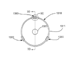
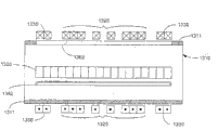
In one embodiment, as describing on Fig. 2 A, 2B, 2C and the 2D, provide an alternative chamber 1310, it makes these problems minimum.The chamber 1310 of CBFR preferably mainly is made of metal (preferred stainless steel etc.), so that structural strength and good vacuum performance to be provided.Yet the axial dielectric that the cylindrical wall 1311 of chamber 1310 is included in the wall 1311 interrupts 1360, this power core district of interrupting in the chamber 1310 middle body or CBFR along the chamber 1310 almost whole length extend.Preferably, as describing on Fig. 2 B, there are 3 apart from one another by the interruption 1360 of opening about 120 degree.As describing on Fig. 2 C, interrupt 1360 groove or the slits 1362 that are included in the wall 1311 of chamber 1310, be formed with seal groove or bearing 1369 around the edge of groove 1362.O annular seal 1367 is contained in the groove 1369.As describing on Fig. 2 D, the whole length of groove 1362 extending chamber 1310 makes enough stainless steel materials form the azimuth continuous part of wall 1311 near two ends, so as to provide structure integrality and for the good quality vacuum seal at the end place ready.In order to improve structural intergrity and to prevent implosion, as describing on Fig. 2 A, chamber 1310 preferably includes the local orientation of many groups ribs 1370, and this orientation, part rib and locular wall 1311 integrally form or by welding etc. and the surface combination of locular wall 1311.
As describing insert 1364 fillings that slit 1362 usefulness are formed by ceramic material on Fig. 2 C.Insert 1364 protrudes into the inside of chamber 1310 a little, and is covered by metal covering 1366 on the inboard, to prevent colliding the secondary plasma emission that causes from a plasma of circulation plasma beam with pottery.1310 the outside in the chamber, insert 1364 is attached to sealing plate 1365, and the sealing plate is built by the O annular seal 1367 and the stainless steel surfaces formation vacuum of locular wall 1311.In order to keep desirable vacuum performance, sealing plate 1365 preferably is made of substrate (preferred glass fibers etc.), glass fibres etc. are soft, and seal more closely than ceramic material with 1367 formation of O ring, especially when inside pressure makes chamber 1310 distortion slightly.
Insert in groove 1362 or ceramics insulator 1364 prevent that preferably electric current from striding slit 1362 and forming electric arcs, and prevent that thus the azimuth mirror image current from forming in locular wall 1311.As described below, image current is the Lenz's law phenomenon, it is the propensity of any magnetic flux change of opposing: for example in the magnetic flux change that takes place in flux coil 1320 during the formation of CBFR.If do not have groove 1362 in the cylindrical wall 1311 of chamber 1310, the magnetic flux of the variation in flux coil 1320 makes equal but reverse induced current is formed in the stainless steel wall 1311, to have offset the magnetic flux change of 1310 the insides in the chamber.Though the image current of induction can be than a little less than the electric current that is applied on the flux coil 1320, but image current tends to reduce very doughtily and apply magnetic field or confining magnetic field in chamber 1310, when not solving, this tends to influence negatively magnetic field topology and the binding feature of change in chamber 1310.The existence of groove 1362 prevents in the orientation of locular wall 1311 continuous part, forms the azimuth mirror image current towards the midplane away from the chamber 1310 of 1310 ends, chamber in locular wall 1311.Can towards unique image current be by locular wall 1311, with the very weak electric current of the longitudinal axis PARALLEL FLOW of groove 1362 away from the middle face carrying of the end of chamber 1310.Such electric current to the axial magnetic confining field of FRC without any influence, because the magnetic mirror image field that is produced by the image current that vertically passes locular wall 1311 only presents radially and azimuthal component.The azimuth mirror image current that forms near the orientation continuous conduction part of the wall 1311 1310 ends, chamber is not inclined to the binding feature that influences negatively and/or change 1310 the insides in the chamber, because near the constraint of the magnetic topology article on plasma body this is inessential.
Except prevent to form the azimuth mirror image current in locular wall 1311, groove 1362 also provides the path of magnetic flux from field and mirror image coil 1325 and quick penetration chambers 1,310 1330.As a result, groove 1362 makes it possible to carry out the inferior Millisecond fine tuning and the FEEDBACK CONTROL of impressed field.
Charged particle among the FRC
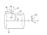
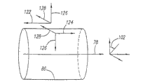
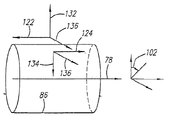
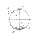
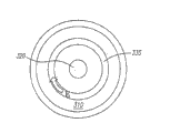
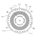
Fig. 3 represents the magnetic field of FRC 70.This system has with respect to its cylindrosymmetry of 78.In FRC, two magnetic line of force districts are arranged: 82 of 80 open and closure.The face of cutting apart these two districts claims interface 84.FRC forms the cylindrical zero-potential surface 86 of magnetic field disappearance thereon.At the middle body 88 of FRC, magnetic field does not obviously change in the axial direction.At end 90, magnetic field obviously changes really in the axial direction.In FRC, along the reversing magnetic field direction of central shaft 78, this draws the term " reverse " in the reverse configuration on the scene (FRC).
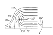
In Fig. 4 A, the magnetic field beyond zero-potential surface 94 is on first direction 96.Is at zero-potential surface 94 on the second direction opposite with first direction 98 with interior magnetic field.If an ion moves on direction 100, the Lorentz force 30 that acts on it points to zero-potential surface 94.By using right-hand rule, be readily appreciated that this situation.For the particle of motion on diamagnetic direction 102, Lorentz force always points to zero-potential surface 94.This phenomenon draws the racetrack that is called the rheotron track, be described below.
Fig. 4 B represents the ion of a motion on resistance magnetic direction 104.Lorentz force in this case points to and leaves zero-potential surface 94.This phenomenon draws the one type of track that is called drift orbit, be described below.The diamagnetic direction of ion is the resistance magnetic direction of electronics, and vice versa.
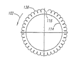
Fig. 5 represents plasma ring or the annulate lamella 106 with the diamagnetic direction rotation of ion.Ring 106 is around zero-potential surface 86 location.The magnetic field 108 that is produced by peripheral plasma layer 106 engages with externally-applied magnetic field 110, forms the magnetic field (this topology of expression on Fig. 3) of the topology with FRC.
The ion beam that forms plasmasphere 106 has temperature, so the speed of these ions forms maxwell's distribution in the framework that the mean angular velocity with ion beam rotates.Collision between the ion of friction speed causes fusion reaction.For this reason, plasma beam layer or power core 106 are called as the colliding beam system.
Fig. 6 represents to be called the main type ion trajectory in the colliding beam system of rheotron track 112.It is the sine wave at center that rheotron track 112 can be expressed as with zero-bit circle 114.Explain that as top magnetic field on zero-bit circle 114 disappears.The plane of track 112 is perpendicular to the axle 78 of FRC.Ion on this track is from diamagnetic direction 102 motions of starting point 116 at them.Have two kinds of motions at the ion on the rheotron track: the vibration on radial direction (vertical) and along 114 translations of zero-bit circle with zero-bit circle 114.
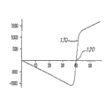
Fig. 7 A is the figure in magnetic field 118 among the FRC.The trunnion axis representative of this figure is the distance of unit from FRC axle 78 with cm.Magnetic field is unit with the kilogauss.Describe as this figure, magnetic field 118 is in the 120 places vanishing of zero-bit radius of circle.
Shown on Fig. 7 B, the particle of motion will experience and point to the magnetic field gradient 126 that leaves zero-potential surface 86 near the zero-bit circle.Magnetic field in zero-bit circle outside is on first direction 122, and the magnetic field inside the zero-bit circle is on the second direction opposite with first direction 124.The direction of gradient drift is by cross product
 Provide, here,
It is magnetic field gradient; So, can understand by using right-hand rule, the direction of gradient drift is on the resistance magnetic direction, no matter ion zero-
Provide, here,
It is magnetic field gradient; So, can understand by using right-hand rule, the direction of gradient drift is on the resistance magnetic direction, no matter ion zero-bit circle 128 in addition or in.
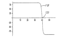
Fig. 8 A is the figure of electric field 130 among the FRC.The trunnion axis representative of this figure is the distance of unit from FRC axle 78 with cm.Electric field is a unit with volt/cm.Describe as this figure, electric field 130 is near the 120 places vanishing of zero-bit radius of circle.
Shown on Fig. 8 B, be (deconfining) that retrains for the ion electric field, it points to and leaves on the direction 132,134 of zero-potential surface 86.As described above, magnetic field at zero-potential surface 86 with interior and be in addition on the rightabout 122,124.Can understand by using right-hand rule,
The direction of drift is on diamagnetic direction 102, no matter ion is in beyond the zero-potential surface 136 still being.
Fig. 9 A and 9B represent to be called another type common-rail among the FRC of drift orbit 138.Drift orbit 138 can be beyond zero-potential surface 114, shown on Fig. 9 A, perhaps in it, shown on Fig. 9 B.If
Drift is preponderated, and then drift orbit 138 rotates with diamagnetic direction, and perhaps, if the gradient drift is preponderated, drift orbit 138 is with the rotation of resistance magnetic direction.The drift orbit of representing on Fig. 9 A and 9B 138 rotates with diamagnetic direction 102 from starting point 116.
Shown on Fig. 9 C, drift orbit can be envisioned as the ringlet that rolls on relatively large circle.Ringlet 142 spins around its axle with direction indication 144.It also rolls on great circle 146 with direction 102.Point 140 will advance along the path identical with 138 in the space.
Figure 10 A and 10B are illustrated in the Lorentz force direction of FRC end 151.In Figure 10 A, show ion and on diamagnetic direction 102, in magnetic field 150, move with speed 148.Can understand by using right-hand rule, Lorentz force 152 tends to ion is back in the closed field line district.So in this case, 152 pairs of ions of Lorentz force retrain.In Figure 10 B, show ion and on the resistance magnetic direction, in magnetic field 150, move with speed 148.Can understand by using right-hand rule, Lorentz force 152 tends to ion is shifted onto in the open field line of force district.So in this case, 152 pairs of ions of Lorentz force go to retrain.
Magnetic in FRC and electrostatic confinement
By on the diamagnetic direction 102 of ion, injecting high energy ion beam, can in FRC, form plasmasphere 106(and see Fig. 5) around zero-potential surface 86.(then going through some distinct methods that form FRC and plasma ring below).In circulation plasmasphere 106, most ion has rheotron track 112(and sees Fig. 6), be high energy, and be nonadiabatic.Therefore, they are to causing that unusual short wavelength's fluctuation of moving is insensitive.
In the plasmasphere 106 that forms under equilibrium condition in FRC, the conservation of momentum is at the angular speed of ion
 Angular speed with electronics
 Between apply relation.This relation is


In equation 1,
 Be the ion atoms ordinal number,
 Be mass of ion,
Be electron charge,
Be mass of ion,
Be electron charge,
 Be the externally-applied magnetic field value, and
 It is the light velocity.3 free parameters are arranged: the externally-applied magnetic field value in this relation
 , electronics angular speed
 Angular speed with ion
If two in them are known, can determine the 3rd from
Angular speed with ion
If two in them are known, can determine the 3rd from equation 1.
Because form plasmasphere 106, the angular speed of ion among the FRC by ion beam is injected into
 Injection kinetic energy by bundle
 Determine,
 Provide by following formula

Here,
 , wherein
 Be the injection rate of ion,
 Be the cyclotron frequency of ion, and
 It is the radius of zero-potential surface 86.The kinetic energy of having ignored intrafascicular electronics is because electron mass
Compare mass of ion
It is the radius of zero-potential surface 86.The kinetic energy of having ignored intrafascicular electronics is because electron mass
Compare mass of ion
 Much smaller.
(fixing for fixing bundle injection rate
 ), can tuning externally-applied magnetic field
 , so that different
 Value is obtainable.As tuning external magnetic field will be shown
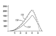
Also be created in the different value of the electrostatic field in the plasmasphere.Explanation feature of the present invention on Figure 11 A and 11B.Figure 11 A represent for identical injection rate (
Value is obtainable.As tuning external magnetic field will be shown
Also be created in the different value of the electrostatic field in the plasmasphere.Explanation feature of the present invention on Figure 11 A and 11B.Figure 11 A represent for identical injection rate (
 =1.35x10
7s
-1), but for the externally-applied
=1.35x10
7s
-1), but for the externally-applied magnetic field value
 3 different values, 3 electric fields that obtained (is unit with volt/cm) curve:
| Curve | Externally-applied magnetic field (
 |
Electronics angular speed (
 |
| 154 |  |
=0 |
| 156 |  |
 |
| 158 |  |
 |
In the last table
 Value is determined by equation 1.People can understand, in
 equation 1,
 >0 means
 >
>
 , make electronics rotate with their resistance magnetic direction.Figure 11 B represents for same group
 The value and
 The current potential of value (is unit with the volt).The trunnion axis representative of Figure 11 A and 11B is that unit represents in the drawings from the distance of
 FRC axle 78 with cm.Electric field and current potential depend on very doughtily

Can explain The above results according to the simple physics basis.When ion rotated with diamagnetic direction, ion was by the Lorentz force magnetic confinement.This represented on Fig. 4 A.For with the electronics of ion equidirectional rotation, Lorentz force is in the opposite direction, makes electronics not restrained.Electronics leaves plasma, and the result causes positive excess.This has just set up one and has prevented that other electronics from leaving the electric field of plasma.The direction of this electric field and value are determined by the conservation of momentum when balance.
When electronics and ion migration, this electrostatic field plays an important role.Correspondingly, an importance of the present invention is, produces the last one electrostatic field in plasmasphere 106, and the value of this electrostatic field is by the externally-applied magnetic field that can adjust easily
 Value control.
As explained above, if
 >0, electrostatic field retrains electronics.Shown on Figure 11 B, by tuning externally-applied magnetic field
Can increase the potential trough degree of depth.Except the very narrow zone near the zero-bit circle, electronics always has a small swing radius.So electronics is with unusual rapid diffusion rate response short wavelength fluctuation.In fact, in case fusion reaction takes place, this diffusion helps to keep potential well.Fusion products ion (having much higher energy) leaves plasma.For keeping the electric charge quasi-neutrality, fusion products must they be pulled out from plasma together with electron synchrotron, mainly take away electronics from the plasma laminar surface.Electron density in plasma surface is very low, and must be replaced with the electronics that fusion products leave plasma together, otherwise potential well can disappear.
>0, electrostatic field retrains electronics.Shown on Figure 11 B, by tuning externally-applied magnetic field
Can increase the potential trough degree of depth.Except the very narrow zone near the zero-bit circle, electronics always has a small swing radius.So electronics is with unusual rapid diffusion rate response short wavelength fluctuation.In fact, in case fusion reaction takes place, this diffusion helps to keep potential well.Fusion products ion (having much higher energy) leaves plasma.For keeping the electric charge quasi-neutrality, fusion products must they be pulled out from plasma together with electron synchrotron, mainly take away electronics from the plasma laminar surface.Electron density in plasma surface is very low, and must be replaced with the electronics that fusion products leave plasma together, otherwise potential well can disappear.
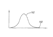
Figure 12 represents the Distribution and Maxwell's Velocity 162 of electronics.Only could arrive plasma surface and leave together with the fusion ion from the electronics of the very high energy of maxwell's distribution tail 160.Maxwell distributes 162 afterbody 160 therefore by producing near the electronics in the high-density region of zero-potential surface-electron collision.These high energy electrons still have small swing radius, make unusual diffusion allow them enough to reach the surface apace to hold the fusion products ion that leaves.These high energy electrons climbing potential wells lose their energy and have very little energy to be left.Though because unusual migration electronic energy is promptly crossed over magnetic field, unusual energy loss trends towards being avoided, because very little energy is moved.
Another consequence of potential well is to be similar to transpiration-cooled strong cooling mechanism to electronics.For example, for the water of evaporation, must give the latent heat of supplying with its evaporation.This heat is supplied with by remaining liq water and surrounding medium, and then, the rapid quickly thermalization of remaining liq water and the replaceable energy of surrounding medium specific heat transmission course is to lower temperature.Similarly, for electronics, the potential well degree of depth equals evaporation of water latent heat.The process of thermalization of the energy by resupplying maxwell's afterbody, electronics are supplied with for climbing the potential well energy needed, so that electronic energy is escaped.So this process of thermalization causes low electron temperature, because it is all more faster than any heating process.Because the difference in quality between electronics and the proton, from energy delivery time of proton approximately be one of about 1800 of the electronics thermalization time.This cooling mechanism also reduces the radiation loss of electronics.This is to the high-rank fuel particular importance, and wherein radiation loss is had atomic number Z(Z>1 greater than 1) the fuel ion strengthen.
Electrostatic field also influences the ion migration.Most of racetracks in the plasmasphere 106 are rheotron tracks 112.Wide-angle collision promptly with the collision of 90 °-180 ° angle of scattering, can become drift orbit to the rheotron track.As mentioned above, the direction of rotation of drift orbit by
 The competition decision of drift and gradient drift.If
Drift is preponderated, and drift orbit rotates with diamagnetic direction.If the gradient drift is preponderated, drift orbit is with the rotation of resistance magnetic direction.This is presented on Figure 13 A and the 13B.Figure 13 A represents that owing to 180 ° of transition from the rheotron track to drift orbit that collision causes this transition takes place at point 172 places.Drift orbit continues with diamagnetic direction rotation, because
The competition decision of drift and gradient drift.If
Drift is preponderated, and drift orbit rotates with diamagnetic direction.If the gradient drift is preponderated, drift orbit is with the rotation of resistance magnetic direction.This is presented on Figure 13 A and the 13B.Figure 13 A represents that owing to 180 ° of transition from the rheotron track to drift orbit that collision causes this transition takes place at point 172 places.Drift orbit continues with diamagnetic direction rotation, because
 Drift is preponderated.Figure 13 B represents another 180 ° of collisions, but under this situation, and the weak and gradient drift of electrostatic field is preponderated.So drift orbit is with the rotation of resistance magnetic direction.
The direction of rotation of drift orbit determines whether it is restrained.The particle that moves on drift orbit also will have the speed parallel with the FRC axle.Particle is gone to the time that the other end takies from the end of FRC, and the result as its parallel motion is called the transit time; Therefore, drift orbit uses the time of transit time magnitude to arrive the end of FRC.As just Figure 10 A is represented, the Lorentz force in the end of FRC only retrains the drift orbit with diamagnetic direction rotation.So, after the transit time, with the losses of ions on the drift orbit of resistance magnetic direction rotation.
This phenomenon causes ion loss mechanism, expects that it exists in all FRC experiments.In fact, in these experiments, ion carries half electric current, and electronics carries second half electric current.Under these situations, the electric field in the plasma is ignored, and the gradient drift always exceeds
Drift.Therefore, all are all lost after the transit time by the drift orbit that the wide-angle collision causes.These laboratory reports than estimating those ions diffusion rates faster of predicting by classics diffusions.
If there is strong electrostatic field,
 Drift exceeds the gradient drift, and drift orbit rotates with diamagnetic direction.Just Figure 13 A has represented this situation in the above.When these tracks reached the end of FRC, they were reflected back in the zone of closed field line by Lorentz force.So they remain in the system of being constrained on.
Electrostatic field in the colliding beam system can be enough strong, so that
 Drift exceeds the gradient drift.So, being similar to this losses of ions mechanism of the loss cone in the lens device by elimination, the electrostatic field of system can be avoided the ion migration.
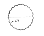
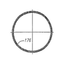
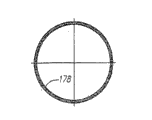
By considering the effect of the low-angle electron-ion collision on the rheotron track, can understand another aspect of ions diffusion.Figure 14 A represents rheotron track 112; Figure 14 B represents track 174, and it is the same track 112 when considering the collision of low-angle electron-ion; Figure 14 C has represented to follow the track 176 of Figure 14 B of the time of 10 double-lengths; And Figure 14 D represents to follow the track 178 of Figure 14 B of the time of 20 double-lengths.Can see that the topology of rheotron track is owing to the collision of low-angle electron-ion changes; Yet their radial vibration amplitude increases in time.In fact, Figure 14 A to 14D in time fertilizer get up the classical diffusion of this expression.
The formation of FRC
The conventional processes that is used to form FRC is mainly utilized oppositely operation of theta pinch field (theta pinch-field).In this conventional method, apply bias magnetic field by external coil around neutral gas back-filling chamber.In case this takes place, gas is just by ionization, and bias magnetic field is frozen in the plasma.Then, the electric current in the external coil is reverse rapidly, and the magnetic line of force that just is being orientated is connected to form closed FRC topology (see figure 3) with the magnetic line of force that had before freezed.This forming process is experience to a great extent, and the means that exist any control FRC to form hardly.Therefore, this method has poor repeatability and does not have any tuning capability thus.
On the contrary, FRC formation method of the present invention allows to control fully and provide transparency and repeatable much higher process.In fact, the FRC that is formed by method of the present invention can be tuning, and the controlling of magnetic field that its shape and other character are applied by external field coil 325 can directly influences.Form with the FRC of method of the present invention and also to cause with the electric field of the mode described in detail above and the formation of potential well.In addition, this method can easily be promoted FRC being accelerated to horizontal parameter of reactor and high-energy fuel electric current, and advantageously makes classical ion bondage become possibility.In addition, present technique can be applied in the compact device, and very reliably and easily realizes the characteristic of the high expectations of all reactor systems.
In the method, FRC forms with circulation plasma beam 335 relation.Be appreciated that because circulation plasma beam 335 is electric currents, so it produces poloidal magnetic field, as the electric current in the round conductor.In circulation plasma beam 335, the externally-applied magnetic field that the magnetic self-fields resistance of its induction is caused by external coil 325.Outside plasma beam 335, the magnetic self-fields is on the direction identical with externally-applied magnetic field.When the gas ions electric current was enough big, self-fields overcame impressed field, and reverse at circulation plasma beam 335 internal magnetic fields, thereby formed as the FRC topology shown on Fig. 3 and 5.
The requirement of FR can be estimated with simple model.Consideration is by having major radius
 And short radius
 <<
<<
 The electric current that carries of rim bearing
 In ring central authorities be with the magnetic field of encircling quadrature
 Suppose circular current
 By having angular speed
 Individual ion carrying.For with radius
 The single ion of circulation,
 Be to external magnetic field
Cyclotron frequency.Suppose
Be to external magnetic field
Cyclotron frequency.Suppose
 Be the average speed of beam ion.Field-reversed being defined as

This means,
 >
>
 , and
, and
Wherein
 Cm, ion beam energy is
 In one-dimensional model, be from the magnetic field of plasma current
 , wherein
 It is the electric current of per unit length.Field-reversed requirement is
>
It is the electric current of per unit length.Field-reversed requirement is
>
 =0.225 kiloampere/cm, wherein
 =69.3 Gausses, and
 =100 eV.For model with periodic ring,
 On axial coordinate, ask average
(s is a ring spacing), if
On axial coordinate, ask average
(s is a ring spacing), if
 , this model can have the average magnetic field identical with one-dimensional model, wherein

Combined beam/rheotron forms technology
An above-mentioned method for optimizing that forms FRC in constrained system 300 is called combined beam/rheotron technology here.This method utilizes rheotron flux coil 320 that low energy plasma ion beam and rheotron are quickened combination.
The first step in this method is, utilizes background plasma source 345, and 310 li are injected the background plasma cloud layer of ring-type basically in the chamber.External coil 325 produces the magnetic field of magnetization background plasma in chamber 310.With short interval,, low energy ion beam is injected in the chamber 310 by traversing the inlet 340 of the externally-applied magnetic field in the chamber 310 basically.As explained above, these ion beams are trapped in the chamber 310 on big rheotron track by this magnetic field.These ion beams can be produced by ion accelerator, for example comprise the accelerator of ion diode and Marx generator.(see R. B. Miller, An Introduction to the Physics of Intense Charged Particle beams(reinforcing band beam of charged particles physics is introduced), (1982)).Can understand that as those skilled in the art inject ion beam one inlet chamber 310, externally-applied magnetic field just will apply Lorentz force to it.Yet, expectation be, ion beam is before arriving circulation plasma beam 335 bundles, not deflection also thereby does not enter the rheotron track.For addressing this problem, with electronics ion beam is neutralized, then, as illustrated on Figure 15, when ion beam 350 was conducted through suitable magnetic field as apply magnetic field unidirectional in the chamber 310, positive charged ions was separated with electronegative electronics.Ion beam 350 thus since this magnetic field obtain electric self poling.This magnetic field also can be produced by for example permanent magnet or the electromagnet along ion beam path.Then be incorporated into constraint during chamber 310, as a result the electric field balance magnetic force that is subjected to of bundle of particle, allow the ion beam drift and be not deflected.Front elevation when Figure 16 represents ion beam 350 contact plasmas 335.As depicted, be advanced into or go out bundle 350 along the magnetic line of force from the electronics of plasma 335, this consumes the electric polarization of bundle thus.At Shu Buzai during by electric polarization, bundle is added in the circulation beam-plasma 335 on the rheotron track of main shaft 315, as (also seeing Fig. 5) shown on Fig. 1.
When plasma beam 335 was advanced on its rheotron track, the ion of these motions formed electric current, and this electric current causes the utmost point to the magnetic self-fields.In order in chamber 310, to produce the FRC topology, be necessary to increase the speed of beam-plasma 335, thus the value of the magnetic self-fields that increase plasma beam 335 causes.When the magnetic self-fields was enough big, this magnetic field was reverse in the direction on the radial distance of axle 315 in plasma beam 335, causes FRC.(seeing Fig. 3 and 5).Be appreciated that and when circulation plasma beam 335 increases, be necessary to increase the impressed field of external coil 325 on speed for keeping the radial distance of circulation plasma beam 335 on the rheotron track.So, a control system is provided, be used to keep the suitable externally-applied magnetic field of arranging by by the electric current of external coil 325.Selectively, can use second external coil that this other externally-applied magnetic field is provided, when plasma beam is accelerated, need it to keep the radius of the track of plasma beam.
For increasing the speed of circulation plasma beam 335 on its track, provide rheotron flux coil 320.With reference to Figure 17, be appreciated that the electric current that increases by rheotron flux coil 320, by Ampere's law, the 310 the inside sensed orientation electric field E in the chamber.Positive charged ions in the plasma beam 335 is quickened by this induction field, causes as above-mentioned field-reversed.It is neutralized as mentioned above and polarizes at ion beam 350() when being added to circulation plasma beam 335, plasma beam 335 makes the ion beam depolarising.
For field-reversed, circulation plasma beam 335 preferably is accelerated to the rotating energy of about 100 eV, and is preferably about 75 eV to 125 eV.For reaching the correlated condition of fusion, circulation plasma beam 335 preferably is accelerated to about 200 KeV, and preferably accelerates to about 100 KeV to 3.3 MeV.
Successfully demonstrated and utilized combined beam/rheotron formation technology to form FRC.Utilization reach 500G externally-applied magnetic field, reach 5kG by the magnetic field and 1.2 of rheotron flux coil 320 from rotating plasma induction
 The vacuum of torr has experimentally been carried out combined beam/rheotron formation technology for 1 li in 1 meter chamber with 1.5 meters of length of diameter.In experiment, background plasma has
 Density, ion beam is to have
 Density,
 The neutral hydrogen bundle of speed, the about 20 μ s(of pulse length highly are locating half).Observed field-reversed.
Rheotron forms technology
Another method for optimizing that forms FRC in constrained system 300 is known as rheotron formation technology here.This technology is based on utilizes rheotron flux coil 320 directly to drive the rheotron induced current with accelerated circulation plasma beam 335.Except the injection of low energy ion beam is unnecessary, the constrained system 300 that a preferred embodiment of this technology utilizes Fig. 1 to describe.
As show that the critical piece in the rheotron formation technology is mounted in chamber 310 central authorities and along its rheotron flux coil 320.Since its separation and winding construction, coil 320 presents very low inductance, and, with the coupling of suitable power supply the time, have low LC time constant, this makes, and rising to rapidly of electric current becomes possibility in the flux coil 320.
Preferably, by excitation external magnetic field coil 325,330, the formation of FRC begins.This provides axial lead magnetic field and radial magnetic field composition near the end, be injected into chamber 310 ionic medium bodies with axial constraint.In case set up enough magnetic field, background plasma source 345 is just encouraged by their power supply.The plasma mobile and note of the ancient Chinese dispersion slightly of guiding magnetic field vertically from the spray gun emission owing to its temperature.When plasma arrives the midplane of chamber 310, set up the cold slow moving plasma layer of continuous, axially extended a, ring-type.
At this moment, rheotron induction flux coil 320 is energized.Rapid ascending current in the coil 320 causes the axial magnetic flux of fast-changing coil inside.Rely on inductive effect, the generation (seeing Figure 18) that this of axial flux increases sharply and cause azimuthal electric field E, azimuthal electric field E passes around the space of flux coil.According to Maxwell equation, magnetic flux intensity is varied to direct ratio in this electric field E and the coil, that is, the rheotron coil current rises to more soon will cause strong more electric field.
Electric field E that induction produces and the charged particle in the plasma are coupled and cause the ponderomotive force of quickening particle in the ring-type plasmasphere.The less quality that relies on them, electronics are the kinds that first experience is quickened.So the initial current that is formed by this process is mainly caused by electronics.Yet enough accelerating time (approximately hundreds of microsecond) also will finally cause ionic current.Turn back to Figure 18, this electric field E quickens electronics and ion in the opposite direction.In case these two nucleic reach their final speed, difference between current is seldom carried by ion and electronics comparably.
As mentioned above, the electric current that is carried by rotating plasma causes self-magnetic field.In the self-magnetic field of setting up by the electric current in the plasmasphere when to become with the magnetic field that applies from external field coil 325,330 be comparable, the foundation of the generation of actual FRC topology.At this moment, magnetic reconnects generation, and the open magnetic line of force that initial outside produces magnetic field begins closure and forms FRC magnetic flux surface (seeing Fig. 3 and 5).
The basic FRC that this method is set up presents the magnetic field and the particle energy of appropriateness, and generally they are not in the relevant running parameter of reactor.Yet as long as the electric current in the rheotron flux coil 320 continues to increase with rapid rate, the induced electricity accelerating field will exist.The effect of this process is that the energy of FRC and total magnetic field continue by force to increase.So the degree of this process mainly is subjected to flux coil power limitations, need large-scale store energy body because continue delivered current.Yet in principle, accelerating system is direct to the relevant condition of reactor.
For field-reversed, circulation plasma beam 335 preferably is accelerated to the rotating energy of about 100 KeV, preferably in the scope of about 75 KeV to 125 KeV.For reaching the relevant condition of fusion, circulation plasma beam 335 preferably is accelerated to about 200 KeV, preferably in the scope of about 100 KeV to 3.3MeV.When ion beam was added to circulation plasma beam 335, as mentioned above, plasma beam 335 was the ion beam depolarising.
Proved successfully that with following parameter level the FRC that utilizes rheotron formation technology forms:
Vacuum-chamber dimensions: about 1 rice diameter, 1.5 meters length;
The rheotron coil radius of 10cm;
The plasma orbit radius of 20cm;
The average external magnetic field that produces in the vacuum chamber reaches 100 Gausses, the mirror ratio that rises to cycle and 2 to 1 of 150 microseconds (source: external coil and rheotron coil);
The characteristics of background plasma (being hydrogen basically) are about 10
13Cm
-3Averag density, less than the kinetic temperature of 10 eV;
The gross energy that the life-span of this configuration stores in being tested limits, and generally is about 30 microseconds.
Injecting the background plasma floor with two groups of coaxial cable rifles that at first are used in the circular shape installation in the inside, chamber experimentizes.Per 8 rifles are installed on one of two mirror image coil groups for one group.Rifle is spaced apart and other group skews relatively with equidistant mode orientation.This layout allows rifle to launch simultaneously, and sets up the peripheral plasma layer whereby.
When setting up this layer, rheotron flux coil is energized.Ascending current in the rheotron coil windings causes the increase of magnetic flux in the coil, and it is curling that this causes azimuthal electric field to center on the magnetic induction accelerator coil.Rising to soon with high electric current in rheotron flux coil produces highfield, and this electric field quickens annular plasmasphere, thereby has responded to a quite big electric current.Enough strong plasma current has produced the magnetic self-fields, and this self-fields changes impressed field and causes the formation of field-reversed configuration.Scope, intensity and the duration of FRC have been discerned with the detailed measurements of B form point loop (B-dot loop).
On Figure 19, represent the example of typical data with the trace of B form point detectable signal.Data and curves A representative is located and in the absolute intensity of the axial component in the magnetic field of radial position place of 15cm at the axial midplane (all 75cm of what end plate leave one's post) of the chamber of experiment.Data and curves B representative is at the axial midplane place of chamber with in the absolute intensity of the axial component in the magnetic field of radial position place of 30cm.Therefore, the curve A data set is illustrated in the magnetic field intensity of (between magnetic induction accelerator coil and plasma) in the fuel plasmasphere, and the curve B data set is depicted in the magnetic field intensity of fuel plasmasphere outside.These data clearly illustrate that, to upside (bearing) between 47 microseconds, and external field still is positive to internal magnetic field in about 23 microseconds, i.e. upside not.The reverse time is subjected to the restriction that rises to of electric current in the rheotron coil.In case arrive peak current in the rheotron coil, the electric current in the fuel plasmasphere just begins to reduce and FRC fails rapidly.Till now, the FRC life-span is subjected to energy stored to limit in experiment.With inject and to capture experiment the same, system can be upgraded longer FRC life-span to be provided and to accelerate to the reactor relevant parameter.
In a word, present technique not only produces compact FRC, but also be stand use and simple realization.Most important ground, the basic FRC that can easily quicken to produce with this method is to any rotating energy and magnetic field intensity that requires level.This fusion to the high-energy fuel bundle is used and classical constraint is vital.
Inductive plasma source
Above-mentioned rheotron and bundle/rheotron FRC forms technology, and the both depends on by flux coil 320 and gives energy to background plasma.Be similar to transformer, the flux coil is carried out the function of the elementary winding of transformer, and plasma plays secondary winding.For this induction system is worked expeditiously, plasma is that the good conductor this point is indispensable.
Opposite with the general conductor as metal, increase with its temperature, the resistance decreasing of plasma also thereby is more conducted electricity.Particularly, the temperature of plasma electron plays an important role, and has determined dissipation (relevant with the electron-ion collision) to a great extent.In fact, dissipation is owing to the resistance that is caused by the electron-ion collision causes: collision frequency is high more, and resistivity is high more.This is because the polymerism in the plasma causes wherein Coulomb collision cross section conductively-closed.Speed (promptly for the Coulomb scattering cross section that collision frequency (Peng Zhuan incidence in succession) is density basically, cover and the heat of collision/scattering electric charge (or average)
 ) function.By definition, v and T
1/2Proportional, σ and v-
4Proportional, perhaps, thus and T
-2Proportional.So, collision frequency
) function.By definition, v and T
1/2Proportional, σ and v-
4Proportional, perhaps, thus and T
-2Proportional.So, collision frequency
 With n T
-3/2Proportional.Resistivity is pressed
With collision frequency opening relationships.Therefore, resistivity and T
-3/2Proportional, notably, irrelevant with density, this true direct result is that even the number of charge carrier increases with density, the number of scattering center also increases.So higher temperature causes higher plasma conductivity and less dissipation loss.
With n T
-3/2Proportional.Resistivity is pressed
With collision frequency opening relationships.Therefore, resistivity and T
-3/2Proportional, notably, irrelevant with density, this true direct result is that even the number of charge carrier increases with density, the number of scattering center also increases.So higher temperature causes higher plasma conductivity and less dissipation loss.
For realizing the performance of the constraint among the FRC preferably, hot plasma is highly to wish for this reason.Under the situation of PEG system, the electron temperature that improves causes improved FRC starting, and (plasma becomes good more electric conductor, plasma and and the flux coil between induction coupling good more), better electric current continues (the plasma resistance rate that reduces causes friction/dissipation loss and thereby current loss still less still less) and higher magnetic field intensity (electric current is strong more, and self-fields is big more).Enough electron temperatures will cause the better coupling (this advantageously trends towards reducing the formation of azimuth mirror image current in locular wall) of flux coil and plasma during initial plasma forms and before the flux coil engages.This will cause again the rheotron of enhancing quicken (less resistivity causes the inductive transfer of better energy from the flux coil to plasma) and heated by plasma (by the oriented energy of giving of rotatory current representative some with thermalization and forward random energies-finally cause plasma to by the flux coil heats), therefore this will increase ion-electron collision time (because higher temperature), reduce dissipation (littler resistivity) and finally create conditions for reaching higher FRC magnetic field (higher electric current causes stronger magnetic field).
For reaching better initial plasma temperature, provide inductive plasma source.Describe as Figure 20 A, 20B and 20C, inductive plasma source 1010 is to be installed in around the end of flux coil 320 in the chamber 310, and comprise single turn shock coil (shock coil) assembly 1030, assembly 1030 is preferred with high pressure (about 5-15 KV) power supply (not shown) feed.By direct gas feed the neutral gas as hydrogen (or other suitable gas fusion fuels) is incorporated into 1010 li in source through Laval (Laval) nozzle 1020.Air-flow is preferably organized ultrafast spray valve control by some, impacts the forward position to produce cleaning.In case gas is discharged and it is distributed on the surface of coil windings 1040 of shock coil 1030 itself from nozzle 1020, winding 1040 just is energized.Ultrafast electric current and magnetic flux in the low inductance shock coil 1030 rise to the very high electric field that causes in the gas, and this electric field causes the injection of the plasma of puncture, ionization and formation subsequently from the central authorities of shock coil 1030 table faced chamber 310.
In a preferred embodiment, shock coil 1030 comprises that with outer shroud 1034 that forms around its periphery and the annular hub 1036 that centers on week formation in it be the annular disk body 1032 on border.Ring 1034 and hub 1036 axially stretch out body 1032 surfaces, form uncovered circular passage 1035.Body 1032, ring 1034 and hub 1036 be the Unitarily molded formation of the suitable non-conducting material by having good vacuum performance and low outgassing behaviour preferably, such material such as glass, Plexiglas's, pirex, quartz or pottery etc.
The plasma radial drift that the pipe box of multistage (shroud) 1012 ring 1034 couplings preferred and shock coil 1030 produce with restriction.Every section 1014 of pipe box 1012 comprises a plurality of axially extended finger pieces 1016.Every section 1014 end comprises mounting bracket 1015.
Annular dish type nozzle body combines with hub 1036 in 1022 around its with the formation Laval mouth 1020 of disputing in week.Nozzle body 1022 has profile in the joint of expansion, the ring-type gas header (gas plenum) 1025 between the face 1037 of defining surface 1024 and hub 1036 towards the surface 1024 of hub 1036.Adjacent with the outer perimeter of nozzle body 1022, surface 1024 has the profile of the expansion of being retracted to, the daraf(reciprocal of farad) that type jet expansion 1023 that extend in the orientation between the face 1037 of defining surface 1024 and hub 1036.
Be attached to hub 1036 reverse side be valve cup ring 1050, several valve seats 1054 be formed on the ring 1050 outsides in.Valve seat 1054 is aimed at the gas feed path 10 52 that forms by hub 1036.
At work, neutral gas is fed to the gas passage 1052 of extend past hub 1036 through the ultrafast spray valve in the valve seat 1054.Because the constriction of jet expansion 1023, gas trend towards feed-in annular gas header 1025 before nozzle 1020 is discharged and are full of it.In case gas is discharged and it is distributed on the surface of coil windings 1040 of shock coil 1030 itself from nozzle 1020, winding 1040 just is energized.Ultrafast electric current in the low inductance shock coil 1030 and magnetic flux rise to the plasma that causes electric field very high in the gas, this electric field to cause puncture, ionization and form is subsequently shown the central authorities of faced chamber 310 from shock coil 1030 injection.
In the group of all strands 1042 that are intended to be lighted a fire together or thigh 1042, electric current rises to preferably well by synchronously.Another possible and favourable selection is, at the thigh of the different groups of different time igniting.Can be deliberately between not on the same group the thigh of participating in 1042, set up and postpone, so that at different time starting on the same group thigh not., importantly,, make that arranging is azimuthal symmetry, and enough coverings of live streamline 1042 are provided for coil 1040 surfaces at any given output pulses not during on the same group thigh in different time starting in one way these stock groups.Interpulse delay is subjected to obtain the restriction of how much neutral gas.In fact, might separate the 5-600 microsecond and evoke such pulse.
In the practice, input working parameter is preferably as follows:
Charging piezoelectric voltage: about 10 to 25 kV phase-splittings power supply
Electric current: reach the total current of about 50 kA all windings by combination
Pulse/rise time: reach about 2 microseconds
Gas pressure :-20 arrive 50psi approximately
Gas header size: every valve about 0.5 to 1cm
3, i.e. emission (per shot) about 4 to 8cm at every turn
3Total gas volume
In an exemplary embodiment, input working parameter is as follows:
The charging piezoelectric voltage: 12 to 17kV phase-splitting power supply, promptly from-12 KV to+12 KV
Electric current: per 3 strands group is 2 to 4.5kA, and promptly 16 to 36kA total current is by all windings of combination
Pulse/rise time: 1 to 1.5 microsecond
Gas pressure :-15 arrive 30psi approximately
Inflation size: every valve 0.5 to 1cm
3, promptly launch 4 to 8cm at every turn
3Total gas volume
Utilize above-mentioned parameter to have following advantageous feature by the plasma of the method for operation generation of this inductive plasma source 1010:
Density~4x10
13Cm
-3
Temperature~10-20 eV
Annular scale~40-50 cm diameter
Axial drift velocity~5-10 eV
Because the shape and the orientation in source 1010, the shape of the plasma of gushing out is annular, and has the diameter of the rotating plasma ring that equals the FRC that will form.In this PEG system, two such inductive plasma source 1010 preferably are placed on arbitrary axial end of chamber 310, and preferred parallel igniting (fire).The plasma distribution of these two formation towards the chamber 310 the axis of centres to drift, 310 the central authorities in the chamber, their form peripheral plasma layer, plasma is quickened by flux coil 320 then, as mentioned above.
RF to ion among the FRC and electronics drives
The RF(radio frequency) current drives (being called rotomak) has been tackled the FRC application, and wherein electric current is mainly carried by electronics.It relates to by two phased antennas generation rotation radial magnetic fields.Electronics is magnetized and is freezing to the rotation magnetic force line.This holding current makes ion be accelerated and till electric current reduces up to the Coulomb collision of ion and electronics.Though Rotomak is unsuitable for ad infinitum holding current, to several milliseconds, it has been successful.
In the FRC of native system, electric current is mainly carried by the ion on the rheotron track, and these ions can not be frozen on the rotation magnetic force line.For stability and classical diffusion, big track ion is important.Replace antenna, drive by electrostatic wave as electronics in the cyclotron and ion.Problem is complete static, because the RF frequency is less than 10 megacycles, so that wavelength (30 meters) is all more much longer than the size of any plasma.Electrostatic field can pass the FRC plasma than electromagnetic wave much easierly.
The electrostatic wave that is produced by electrode is designed to propagate with the general bearing speed near ion.If the average speed of this Bob ion is propagated soon, it will speed up them and therefore compensates because the towing that the ion-electron collision causes.Yet, electronics also by with from Coulomb collision quicken.In this case, ripple must have the speed slower than electronics average speed, and electronics will speed up ripple.Average velocity of electrons is less than average ion speed, so electronics must drive with two different frequencies.Higher frequency will be to ion, and preferably by the external circuit energize.For electronics, can obtain energy with lower frequency.
Electrode system
Figure 21 A and 21B go up expression four utmost point RF drive systems.As depicted, RF drives and comprises four utmost point cyclotrons 1110 that are positioned at chamber 310 and have 4 gapped 1114 elongated azimuthal symmetry electrode 1112 therebetween.Four utmost point cyclotrons 1110 preferably produce with the direction identical with the orientation speed of ion but with the potential wave of bigger speed rotation.Suitably the ion of speed can be captured in this ripple, and is reflected periodically.This process increases the momentum and the energy of fuel ion, and this increases to be delivered to by collision and does not have captive fuel ion.By injecting neutral particle, can be replaced from the fuel ion of plasma 335 with the speed of any routine.
The method of a selectable additional exciting current is to be used near the additional field coils of settling flux coil 325 and four utmost point cyclotrons 1,110 1116 to enlarge electrode systems, and encourages these coils with half of the frequency of cyclotron electrode 1112.Yet the following discussion that provides here is used to illustrate unique pattern (not having field coil 1116) of electrode.
The electrode of 2 and 4 electrode configurations of explanation on Figure 21 C.
On Figure 21 C, illustrate for space r<r
bIn vacuum, with shown in apply the current potential that voltage is produced by electrode.Those expression formulas are to minimum harmonic.They obtain by separating following Laplace's equation with suitable boundary condition.

For two utmost point cyclotrons,
, for
 (6)
(6)
=
 , for
, for


Because
 On θ, it is the cycle, so it can be launched into Fourier series, promptly with 2 π

And, u
nSatisfy equation

If n=2,4 ... Deng, then


Minimum harmonic is

Higher harmonics is

Velocity of wave on azimuth direction is
So higher harmonics has less phase velocity and amplitude.These are commented either way being suitable on Figure 21 C.For FRC rigidity rotation body balance the time, frequencies omega can be near the speed ω of ion
iSo, for
 =1,
=1,
 For
For
 =2,
=2,
 , and wave amplitude can be much lower; Therefore, only consider that minimum harmonic is good being similar to.
Plasma effect
The response energy of plasma is described with dielectric tensors.Produce plasma current according to following charge conservation equation electric field, plasma current produces separation of charge.

Wherein,
 Be current density, ρ is a charge density.Suitable equation is
Perhaps

Wherein,
 Be dielectric tensors,
 It is polarizability.If include only the contribution of electronics, tensor
 Be the diagonal angle, one-component is.

Wherein, n is a density, and B is FRC magnetic field.N and B change rapidly with r, the inherent r=r of plasma
0Face on B=0.Suppose that electronics has the little radius of gyration, and same gyrofrequency
 Relatively electric field change is very slow, derives
 Expression formula.This is similar near zero-potential surface is false.The feature track changes to the rheotron track that electric field is had much smaller response from drift orbit, promptly at r=r
0Zero-potential surface near
Expression formula.This is similar near zero-potential surface is false.The feature track changes to the rheotron track that electric field is had much smaller response from drift orbit, promptly at r=r
0Zero-potential surface near

 Ion mainly has the rheotron track, and is very little to the response of electric field for drift orbit, because electric field is with speed
 Change.
Net result is that the La Pula equation is replaced by following equation

Must find the solution it on the numerical value.At r=r
0Near addition Item disappears.For four utmost point situations, the current potential of minimum harmonic has following form

Has similar type for two utmost point situations.With ion (or electronics) rightabout on the ripple propagated will be left in the basket.
The acceleration that causes by the ion of in electrostatic wave, capturing
We the supposition,
 , so that ripple
 Quicker than ion.For ion supposition standard rigidity rotation body distribution function

The distribution function of the minimizing of being concerned about is

The velocity of wave of the electrostatic wave that is produced by four utmost point cyclotrons is
 If
If

Then ion motion is faster than wave reflection.
This increases wave energy, that is,
If

Then ion motion is slower than wave reflection, and ripple is with following rate loss energy

The net result variable
Variation simplify, that is,

Approximate

Cause

This has the form similar with Landau damping, but physically is not identical, because Landau damping (growth) is a linear phenomena, and this obviously is non-linear.
Because

If
 , wave energy is without any variation.If
 Or
Or
 , wave energy reduces; For
 , wave energy increases.The explanation of this and Landau damping is similar.First kind of situation
 Down, the slow ion of walking than ripple is more than the fast ion of walking than ripple.Therefore, wave energy reduces.In reverse situation
Down, wave energy increases.Former instance is suitable for keeping ion energy and momentum with four utmost point cyclotrons.Current drives that Here it is.Latter instance provides the basis for transducer.Equation (22) and (23) can be used to assess the applicability to the fusion reactor condition.
Down, the slow ion of walking than ripple is more than the fast ion of walking than ripple.Therefore, wave energy reduces.In reverse situation
Down, wave energy increases.Former instance is suitable for keeping ion energy and momentum with four utmost point cyclotrons.Current drives that Here it is.Latter instance provides the basis for transducer.Equation (22) and (23) can be used to assess the applicability to the fusion reactor condition.


Wherein,
 Determine by equation (24) and (25).
For simplifying integration, use
 (value under the peak density is the lower limit of wave amplitude) replaces


It is linear ion density.I=1,2 adapt to two types ion, and this is the situation in the reactor normally.
Detailed calculated show wave amplitude
 Be maximum slit voltage (2V
0) about 1/10th.This will determine the restriction of this RF driving method.V
0The maximum slit voltage that to be able to be kept (may about 10 kV) restriction to the 1cm slit.
Be maximum slit voltage (2V
0) about 1/10th.This will determine the restriction of this RF driving method.V
0The maximum slit voltage that to be able to be kept (may about 10 kV) restriction to the 1cm slit.
The reactor requirement
For current drives, preferably with frequency
 Power P
iPass to ion, and, preferably with frequency
Power P
iPass to ion, and, preferably with frequency
 Power P
ePass to electronics.This is with the Coulomb interactions between compensate for electronic and the ion, and Coulomb interactions reduces ion velocity and increases velocity of electrons.(do not have under the condition of power transmission, Coulomb collision can cause electronics speed identical with ion and no current).Keep the average electric field of electronics and ionic equilibrium to provide by following formula
Power P
ePass to electronics.This is with the Coulomb interactions between compensate for electronic and the ion, and Coulomb interactions reduces ion velocity and increases velocity of electrons.(do not have under the condition of power transmission, Coulomb collision can cause electronics speed identical with ion and no current).Keep the average electric field of electronics and ionic equilibrium to provide by following formula
Wherein,
 Be electric current/unit length,

It is resistance/unit length.
 ,
,
 ,
,
 Be electronics and linear ion density,
 , wherein
 ,
,
 It is the atomic number of ion;
 With
With
 The momentum transfer time from the ion to the electronics.Average electric field is identical for ion or electronics, because for quasi-neutrality,
, and electric charge is opposite.The power that must be delivered to ion is
The momentum transfer time from the ion to the electronics.Average electric field is identical for ion or electronics, because for quasi-neutrality,
, and electric charge is opposite.The power that must be delivered to ion is

The power that can obtain from electronics is

Wherein,
 And
And

Refuel in order to drive with RF, fuel can be with by the fusion time
 With
With
 Given speed is changed with any energy, n
1And n
2Be plasma ion density,
It is reactivity.Quantity is in second.The neutral substance that injects (the fuel ion that replaces burning to disappear) since Coulomb collision will the Millisecond time (for 10
15Cm
-3The reactor density of magnitude) rapidly ionization and accelerate to average ion speed.Yet it is right that this needs
Given speed is changed with any energy, n
1And n
2Be plasma ion density,
It is reactivity.Quantity is in second.The neutral substance that injects (the fuel ion that replaces burning to disappear) since Coulomb collision will the Millisecond time (for 10
15Cm
-3The reactor density of magnitude) rapidly ionization and accelerate to average ion speed.Yet it is right that this needs
 Increase and the increase that power is transmitted, to keep stable state.This increase is

It will increase required power and be delivered to about 2 times.
Can and refuel for current drives power is provided, and be no more than the maximum slit voltage magnitude of 10 kV/cm.Consider that frequency will be that 1-10 megahertz and magnetic field will be 100 kilogauss, can not expect any puncture.Being necessary for the power that current drives transmits with refueling all is identical to any current driving method.Yet the RF technology of 1-10 megahertz has been the high efficiency technical of setting up for many years.Use the described method of electrode rather than antenna to have sizable advantage, because the condition that the field is run through is much looser than electromagnetic wave.So this method has the advantage of circulating power and efficient.
Fusion
Have a mind to the free burial ground for the destitute, above-mentioned being used for forms these two technology of FRC or other similar technology in closed system 300 the insides can produce the plasma with the performance that is suitable for causing therein nuclear fusion.More particularly, can quicken the FRC that forms by these methods to any rotating energy and magnetic field intensity that requires level.Use and classical constraint for the fusion of high-energy fuel bundle, this is vital.Therefore, in constrained system 300, might capture and retrain the period that energetic plasma Shu Chixu is enough to cause its fusion reaction.
Be to adapt to fusion, the FRC that is formed by these methods preferably is accelerated to the rotating energy and the magnetic field intensity of proper level by the rheotron acceleration.Yet for any reaction that will take place, the fusion meeting needs one group of specific physical condition.In addition, be the effective burning consumption and the acquisition positive energy balance that realize fuel, fuel must keep this state constant basically for a long time.This point is important, because high kinetic temperature and/or energy characterization fusion correlation behavior.Therefore, the foundation of this state needs sizable energy input, only works as most fuel and stands fusion, and this could recover.As a result, fuel confinement time must be longer than its burning time.This has just caused the positive energy balance, thereby causes net energy output.
A great advantage of the present invention is that described here constrained system and plasma are that can be arranged long confinement time,, surpass the confinement time of fuel combustion time that is.So, the typicalness of fusion with following physical condition (their can based on fuel and mode of operation and change) be feature:
The average ion temperature: about 30 to 230 keV, preferably about 80keV is to 230 keV;
Average electron temperature: about 30 to 100 keV, preferred about 80 to 100 keV;
The coherent energy of fuel cluster (injecting ion beam and circulation plasma beam): about 100 keV are to 3.3 MeV, and preferably about 300keV is to 3.3 MeV;
The total magnetic field: about 47.5 to 120 kG, preferred about 95 to 120 kG(externally-applied magnetic fields are about 2.5 to 15 kG, preferred about 5 to 15kG);
Classical confinement time: greater than the fuel combustion time, preferred about 10 to 100 seconds;
Fuel ion concentration: about 10
14Arrive less than 10
16Cm
-3, preferred about 10
14To 10
15Cm
-3
Total fuel power: in the scope of about 50 to 450 kW/cm (power of every cm chamber length)
For adapting to the fusion state that specifies above, FRC preferably accelerates to the level of relevant rotating energy, is preferably about 100 keV to 3.3 MeV, and more preferably from about 300 keV are to 3.3 MeV, and the magnetic field intensity level is preferably about 45 to 120kG, more preferably 90 to 115 kG.In these levels, high energy ion beam (be neutralized and polarize as above-mentioned) can be injected among the FRC and be captured to form the plasma beam layer, and wherein, the plasma beam ion is by magnetic confinement, and the plasma beam electrons is by electrostatic confinement.
Preferably, electron temperature keeps to the greatest extent actual capabilities low like that reducing the bremstrahlen amount, otherwise it can cause radiation loss.Electrostatic energy trap of the present invention provides the effective means that realizes this purpose.
Ion temperature preferably remains on the level that efficient burning consumption is provided, because the fusion cross section is the function of ion temperature.It is essential that the high DIRECT ENERGY of fuel ion beam provides classical transport, as discussing in using at this.It also makes the influence minimum of unsteadiness to the fuel plasma.Magnetic field is with bundle rotating energy unanimity.It is partly produced by plasma beam (self-fields), itself provides again to keep support and the power of plasma beam on the track that requires.
Fusion products
Fusion products are mainly producing in the power core near the zero-potential surface 86, by to interface 84 diffusion, and their gush out therefrom (seeing Fig. 3 and 5).This is (because homo-ion collision does not change barycenter, so do not make their change field line) that causes owing to the collision with electronics.Because their kinetic energy (the fusion products ion has the energy more much higher than fuel ion), fusion products can easily be crossed over interface 84.In case they surmount interface 84, as long as their experience the scattering from ion-ion collision, they just can leave along the open field line of force 80.Though this collision process does not cause diffusion, it can change the direction of ion velocity vector, makes its parallel sensing with magnetic field.These open field line of forces 80 are connected the FRC topology of core with the even externally-applied magnetic field that provides in FRC topology outside.Product ion is gushed out on different field lines, and they are following these field wires with an Energy distribution.Advantageously, product ion and charging neutrality electronics are gushed out with the form of the rotating ring pencil of forms two ends from the fuel plasma.For example, for the p-B of 50 megawatts
11Reaction design, these bundles will have the radius of about 50cm and the thickness of about 10cm.In the high-intensity magnetic field of finding outside interface 84 (generally about 100 kilogauss), product ion has a relevant radius of gyration and distributes, for the product ion of high energy, and the maximum variation about this distributes from the minimum value of about 1cm to 3cm.
At first, product ion have by
 With
With
 The energy of the vertical and rotation of expression.v
PerpBe and the relevant orientation speed of rotation that centers on as the field line of orbit centre.Because the back disperseed away near field line left the FRC topology, rotating energy can reduce, and total amount is still constant.This is the result of adiabatic invariance of the magnetic moment of product ion.Well-known in this specialty, in magnetic field around track and the charged particle of row has the magnetic moment relevant with their motion.Under the situation of the particle that moves along slow variation magnetic field, also exist by
The energy of the vertical and rotation of expression.v
PerpBe and the relevant orientation speed of rotation that centers on as the field line of orbit centre.Because the back disperseed away near field line left the FRC topology, rotating energy can reduce, and total amount is still constant.This is the result of adiabatic invariance of the magnetic moment of product ion.Well-known in this specialty, in magnetic field around track and the charged particle of row has the magnetic moment relevant with their motion.Under the situation of the particle that moves along slow variation magnetic field, also exist by
 The adiabatic invariance of the motion of describing.Around their magnetic line of force separately around track and the product ion of row has the magnetic moment adiabatic invariance relevant with such motion with them.Show by the dispersion of field line because B is reduced to 1/10(), draw v thus
PerpBe reduced to about 1/3.2 equally.So, when product ion arrives even place, their rotating energy can less than they gross energy 5%.In other words, nearly all energy is in the longitudinal component.
The adiabatic invariance of the motion of describing.Around their magnetic line of force separately around track and the product ion of row has the magnetic moment adiabatic invariance relevant with such motion with them.Show by the dispersion of field line because B is reduced to 1/10(), draw v thus
PerpBe reduced to about 1/3.2 equally.So, when product ion arrives even place, their rotating energy can less than they gross energy 5%.In other words, nearly all energy is in the longitudinal component.
Power conversion
DIRECT ENERGY converting system of the present invention comprises as the reversed cyclotron transducer (ICC) 420 shown in Figure 22 A and 23A go up, it and power core 436 couplings of colliding beam fusion reactor (CBFR) 410, composition plasma electric generation system 400.The 2nd ICC(is not shown) can be placed into the left side of CBFR 410 symmetrically.Magnetic can cut 486 between CBFR 410 and ICC 420, forms when CBFR 410 and ICC 420 magnetic fields cross.
Before describing ICC 420 and work thereof in detail, provide the commentary of typical cyclotron.In traditional cyclotron accelerator, the energetic ion with speed vertical with magnetic field rotates circlewise.The orbit radius of energetic ion is determined by magnetic field intensity and their charge-mass ratio, and increases with energy.Yet the speed of ion and their energy are irrelevant.This fact is utilized in the design of cyclotron accelerator.
With reference to Figure 24 A, traditional cyclotron accelerator 700 comprises two mirror image C shape electrodes 710, and it forms the D shape chamber that is placed in the uniform magnetic field 720, and it is the vertical field line of the page that uniform magnetic field 720 has with the plane of symmetry of electrode.Between C shape electrode (seeing Figure 21 B), apply vibration potential.Ion I sends from the source that is placed on cyclotron 700 central authorities.Adjust magnetic field 720, make the speed of ion mate the frequency of current potential and relevant electric field.If an ion I is in the slit 730 of crossing on the direction identical with direction of an electric field between the C shape electrode 710, it just is accelerated.By speeding-up ion I, its energy and orbit radius increase.When this ion had been advanced semi arch (not experiencing energy increases), it recrossed slit 730.Electric field between the C shape electrode 710 has been put upside down direction now.Ion I is accelerated again, and its energy further increases.If the speed of ion continues the frequency (seeing Figure 24 C) of coupling oscillating electric field, this process is crossed slit 730 at each ion and is all repeated.Otherwise if particle is crossed slit 730 when electric field is on the rightabout, it will be decelerated and return source in central authorities.Only having the particle that the initial velocity vertical with magnetic field 720 cross slit 730 in the appropriate phase of oscillating electric field just will be accelerated.Therefore, suitable phase place is important to quickening.
In principle, cyclotron can be used for extracting kinetic energy from the pencil beam of identical energetic ion.Proton observed slowed down with cyclotron but do not have Energy extraction, as Bloch and Jeffries at " physical comment ", 80,305(1950) described in.Ion can be injected in the chamber, makes them enter into deceleration phase place with respect to oscillating field.Then, all these ions will make as the track T of the speeding-up ion shown on Figure 24 A reverse.Because same electric field interacts when slowing down, and their kinetic energy converts the oscillating electric field energy in the circuit to, cyclotron is the part of this circuit when ion.To realize that meeting is with the very direct conversion to electric energy of high efficiency generation.
In fact, the ion of ion beam will might phase place enter cyclotron with institute.Unless the phase place that compensation changes in the cyclotron design, half ion will be accelerated, and second half will be decelerated.As a result, in fact maximum conversion efficiency will be 50%.In addition, annular fusion products ion beam discussed above is a unsuitable geometry for traditional cyclotron.
Go through very much as following, ICC of the present invention adapt to the annular feature of fusion products bundle of the FRC that leaves fusion reactor power core and ion in bundle random phase and the dispersion of their energy.
Get back to Figure 22 A, the part of the power core 436 of on the left side diagram CBFR 410, wherein, plasma fuel core 435 is constrained on partly because among the FRC 470 that the magnetic field that is applied by external field coil 425 forms.FRC 470 comprises closed field line 482, interface 484 and the open field line of force 480.As noted above, the performance of the annular beam 437 of FRC 470 decision fusion products.The open field line of force 480 is left power core 436 can cut (cusp) 486 extensions to magnetic.As noted above, fusion products are gushed out from power core 436 with the form of the annular beam 437 that comprises energetic ion and charging neutrality electronics along the open field line of force 480.
The geometry of ICC 420 is as the cylinder of the hollow with about 5 meters length.Preferably, 4 or the half-cylindrical electrode 494 that more has a little straight slot 497 constitute cylinder surfaces.At work, in the alternation mode vibration potential is added on the electrode 494.Electric field E in the transducer has the quaternary structure that shows as on the end view drawing of representing on Figure 22 B.Electric field E disappears on symmetry axis, increases with radius is linear; Peak value is 497 places in the slit.
In addition, ICC 420 comprises the external field coil 488 of the uniform magnetic field in the hollow circular cylinder geometry that forms ICC.Because the electric current ICC field coil 488 of flowing through in the side opposite, so the field line 496 among the ICC 420 is stretching in the opposite direction with the side of the open field line of force 480 of CBFR 410 with the sense of current of the CBFR field coil 425 of flowing through.In the distal-most end from the power core 436 of CBFR 410, ICC 420 comprises ion trap 492.
The magnetic that is symmetry between CBFR 410 and ICC 420 can cut 486, and here, the field line 496 among the open field line of force 480 and the ICC 420 merges.Circulating electron gatherer 490 is placed in magnetic and can cuts around 486, and with ion trap 492 electric coupling.As described below, magnetic can be cut 486 magnetic field and will restraint 437 axial velocity with high efficiency and convert rotary speed to.Typical ion trajectory 422 in Figure 22 C explanation transducer 420.
These ions have and are approximately equal to initial gross energy promptly
 Rotational energy arrive magnetic and can cut 486.Arrive magnetic at ion and can cut 486 o'clock, ion energy and ion initial radium r are arranged
0Distribution.Yet, initial radium r
0Trend towards approximate and initial velocity v
0Proportional.Radial magnetic field and radially Shu Sudu be created in Lorentz force on the azimuth direction.The magnetic field of cutting 486 places in meeting does not change particle energy, but initial axial velocity
Rotational energy arrive magnetic and can cut 486.Arrive magnetic at ion and can cut 486 o'clock, ion energy and ion initial radium r are arranged
0Distribution.Yet, initial radium r
0Trend towards approximate and initial velocity v
0Proportional.Radial magnetic field and radially Shu Sudu be created in Lorentz force on the azimuth direction.The magnetic field of cutting 486 places in meeting does not change particle energy, but initial axial velocity
 Convert residue axial velocity v to
zWith orientation speed
, here,
Convert residue axial velocity v to
zWith orientation speed
, here,
 Orientation speed
 Can determine from the canonical momentum conservation


Wherein,
It is cyclotron frequcncy.The rotational frequency of ion is about 1-10 MHz, is preferably about 5-10 MHz, and this is the frequency that generating takes place.
Can cut 486 for ion passes, effectively the ion radius of gyration must cut 486 in radius r greater than meeting
0The width at place.Reduce axial velocity to 1/10, consequently remaining axial energy will reduce to 1/100, be experimentally quite feasible.So, 99% ion energy will convert rotational energy to.Ion beam has v
0And r
0The distribution of value.Yet, because r
0With v
0Proportional, as in the past showing by performance that the efficient that converts rotational energy to all can be 99% for all ions based on the reactor of FRC.
As describing on Figure 22 B, the symmetry electrode structure optimization of ICC 420 of the present invention comprises 4 electrodes 494.The oscillating circuit (not shown) is connected to electrode structure 494, so that instantaneous voltage and electric field are as directed.Voltage and accumulator with
 Hunting of frequency.The azimuthal electric field E at explanation 497 places on Figure 22 B and Figure 25 in the slit.Electric field in the slit 497 of Figure 25 explanation between electrode 494 and ion are with angular speed
 The field of its experience during rotation.Be apparent that in a complete rotation, particle will alternately experience by the order of initial phase decision and quicken and deceleration.Except azimuthal electric field
Radial electric field is also arranged outward,
The field of its experience during rotation.Be apparent that in a complete rotation, particle will alternately experience by the order of initial phase decision and quicken and deceleration.Except azimuthal electric field
Radial electric field is also arranged outward,
 Azimuthal electric field
 497 maximums in the slit, and reduce and reduce with radius.Figure 22 supposes remain unchanged radius rotation of particle.Because will always surpassing, the gradient in the electric field, deceleration quicken.Boost phase increases ionic radius, so that ionic radius will be bigger when ion runs into retarding field next time.Decelerating phase will preponderate, and irrelevant with the initial phase of ion, because azimuthal electric field
Gradient always positive.Therefore, energy conversion efficiency be not limited to by the initial phase problem relevant with traditional cyclotron cause 50%.Electric field
497 maximums in the slit, and reduce and reduce with radius.Figure 22 supposes remain unchanged radius rotation of particle.Because will always surpassing, the gradient in the electric field, deceleration quicken.Boost phase increases ionic radius, so that ionic radius will be bigger when ion runs into retarding field next time.Decelerating phase will preponderate, and irrelevant with the initial phase of ion, because azimuthal electric field
Gradient always positive.Therefore, energy conversion efficiency be not limited to by the initial phase problem relevant with traditional cyclotron cause 50%.Electric field
 Also be important.It also vibrates and is producing clean effect in the radial direction, this clean effect beam trajectory turn back to as the vertical plane of axle on Figure 22 C on have the original radius of zero velocity.
Ion always process and the strong focusing principle by its deceleration is similar, and strong focusing principle is the substantive characteristics of modern accelerator, as described in the U.S. Patent No. 2736799.If magnetic field has positive gradient, the combination of positive lens (focusing) and negative lens (defocusing) is positive.Explanation strong-focusing quadrupole-doublet lens on Figure 26.First lens focus on the x direction, and defocus on the y direction.Second lens is similarly, but x and y performance are exchanged.Magnetic field disappears on symmetry axis and has the positive radial gradient.For the ion beam that passes two lens, net result is all to focus on all directions, with irrelevant by order.
Comprise strong axial magnetic field and be operated in TE for passing
111The bundle of the resonant cavity of pattern has been reported similar result (seeing Yoshikawa etc.).This device is called " peniotron " (peniotron).At TE
111Under the pattern, resonant cavity has standing wave, and wherein electric field has four utmost point symmetry.Among these results and the result described here some are similar in nature.Have quantitative difference: resonant cavity size much bigger (10 meters length) also is operated in much higher frequency (155 MHz) and magnetic field (10 T).Extract the energy demand Rectenna from the high-frequency ripple.The energy spectrum of bundle has reduced conversion efficiency.The existence of two kinds of ions is more serious problems, but conversion efficiency is to producing the D-He of 15 MeV protons
3Reactor is enough.
The single particle track 422 of a particle on Figure 22 C in the explanation ICC 420.This result is obtained by computer simulation, and equifinality also obtains for peniotron.In certain radius r
0The ion that enters is along the length spiral of ICC, and losing initial rotation energy post-concentration to having same radius r
0Circle on a bit.Initial condition is asymmetric; End-state reflects this asymmetry, but it and initial phase are irrelevant.So all particles all are decelerated.Bundle in the ion trap end of ICC be again annular with similar size.Axial velocity can be reduced to 1/10, and the corresponding increase of density.For single particle, 99% extraction efficiency is real.Yet, various factors, for example the vertical rotation energy of the annular beam before entering transducer can reduce this efficient about 5%.The electrical power extraction can be at about 1-10 MHz, and preferably about 5-10 MHz causes additionally reducing of conversion efficiency for being connected to the power adjustment that electrical network carries out.
Shown on Figure 23 A and the 23B, the embodiment of the electrode structure 494 among the selectable ICC 420 can comprise the semicircular electrode of two symmetries and/or the tapered electrode 494 that attenuates towards ion trap.
Adjustment to the ion dynamics inside the main field of ICC 420 can utilize two ancillary coil groups 500 and 510 to finish, shown in Figure 27 A and 24B.These two coil groups 500 and 510 all comprise the adjacent conductor that has current in opposite, so magnetic field has among a small circle.As schematically showing on Figure 27 A, magnetic field gradient will change ion rotational frequency and phase place.As schematically showing on Figure 27 B, multipole magnetic field will produce pack, as in the linear accelerator.
Reactor
Figure 28 illustrates 100 megawatt reactors.The generator that cuts shows fusion power core district, the flux coil that it has the superconducting coil that applies uniform magnetic field and is used to form the magnetic field with field-reversed topology.The opposite end in contiguous fusion power core district be the ICC energy converter that is used for the kinetic energy of fusion products directly is converted to electric energy.The support equipment of the such reactor of explanation on Figure 29.
Propulsion system
The exploration of the solar system (beyond reaching) needs the available best chemistry or the propulsion capability of electric propulsion system of surpassing far away.Propelling for the advanced person is used, and the present invention has maximum hope: simplicity of design, high thrust, height ratio momentum, high-specific-power density, low mass of system and almost unactivated fuel.
According to plasma thrust propulsion system of the present invention, utilize when fusion products and contain therein kinetic energy during to discharge from the fusionplasma mandrel.Figure 30 and 31 has schematically shown system 800.This system comprises aforesaid FRC power core 836 colliding beam fusion reactors, comprising fusion fuel core 835.This reactor also comprises magnetic field generator 825, current coil (not shown) and ion beam implanter 840.Aforesaid ICC DIRECT ENERGY transducer 820 is coupled with an end of power core 836, and tackles approximately half fusion products particle, and these particles are gushed out with the form of annular beam 837 from the two ends of power core 836.As mentioned above, ICC 820 slows down them by the reversed cyclotron process, and their kinetic energy is converted to electric energy.Magnetic nozzle 850 is settled adjacent to the other end of power core 836, and residue fusion products particle is directed in the space as thrust T.The annular beam 837 of fusion products flows to from an end of fusion power core 836 along field line 837 ICC 820 carrying out power conversion, and from the other end of power core 836 along field line 837 mass flowing nozzles 850 to be used for thrust T.
By thermoelectric energy transducer (TEC) 870 bremstrahlen is converted to electric energy.The bremstrahlen energy of being changed by TEC 870 is not delivered to Brayton cycle heat engine 880.Waste heat discharge is in the space.Power control subsystem (810, see Figure 32) the active and electric receiver (sink) with heat energy of monitoring institute, so that the system of keeping is under the stable state running and an independently energy (being fuel cell, battery etc.) is provided, so that from the running of non-operating condition starting space vehicle and propulsion system.Because fusion products are charged
 Particle so system does not need to use thick and heavy radiation and neutron shield, thereby is characterised in that with other nuclear space propulsion systems and compares, and has significantly reduced mass of system.
For the 100 MW p-B that have as the design of describing on Figure 31
11Fusion core example, the performance of plasma thrust propulsion system 800 is a feature with following kinetic parameter:
Specific impulse
 1.4
s
1.4
s
Thrust power
 50.8 MW
Thrust power/gross output
0.51
Thrust
 28.1N
28.1N
Thrust/gross output
 281 mN/MW
Mission critical performance/restriction tolerance to all spacecrafts is mass of system.Main quality part on Figure 31 and 32 in the explanation plasma thrust propulsion system 800.For quiet rum, fusion core 835 needs the injecting power of about 50 MW.System produces nuclear (particle) power of about 77 MW, and it half is recovered with the efficient up to 90% in DIRECT ENERGY transducer 820.Therefore, need 11.5 extra MW to keep reactor, this power is supplied with by TEC 870 and Brayton Thermal Motor 880.
Main thermal source in the plasma thruster propulsion system 880 is caused by bremstrahlen.TEC 870 reclaims about 20% radiation, and promptly 4.6 MW transmit about 18.2 MW to closing circulation Brayton Thermal Motor 880.Brayton Thermal Motor 880 comprises heat exchanger 860, turbine generation device, compressor 882 and radiator 886, shown on Figure 31.The power of residue 7 MW of reactor needs is kept in 880 supplies of Brayton engine, and other 11 MW directly are discharged in the space by radiator.
Closing circulation Brayton Thermal Motor is that conversion is effectively selected by the maturation of the superfluous heat of TEC 870 discharges.In the Brayton engine, the temperature of largest loop is subjected to material to consider restriction, its restriction maximum heat power cycle efficient.According to the standard performance figure of Brayton engine, can extract some design points.Typical efficient can reach up to 60%.For present circumstances, need 7 MW to be recovered, therefore, only the efficient of 40% conversion used heat is only acceptablely, and this efficient is in the limit of current obtainable traditional B rayton engine.
According to the typical specific mass parameter of advanced person's industrial technology, promptly in the scope of 3 kg/kWe, calculate the part quality (deduction radiator) of whole Brayton engine.Turbine machine (comprising compressor, power turbine and heat exchanger) lumps together total subsystem quality of 18 MT.
Heatsink mass is estimated as 6 MT, and preferred the use has the heat tubesheet of the state of the art high thermal conductivity.
Important system weight is also from the magnet 825 of confined plasma core 835.Superconducting magnet coil 825 is preferably made by Nb3Sn, and it stably is operated in the magnetic field of 4.5K and 12.5-13.5 T.It is not stricter that Nb3Sn compares the other materials of being considered to the requirement of low temperature.The magnetic field of 7 teslas require and the situation of about 7.5 meters device length under, coil needs the lead of year 56 kA electric currents of 1500 circles.Use 0.5cm radius lead, the gross mass of this coil is about 3097 kg.The liquid helium cooling system is made up of two pumps, has one at an end of main coil.About 60 Kg of the gross mass of these pumps.The external structure shell is from external support magnet and all internal parts.It is made by 0.01 meter thick kevlar/ carbon-carbon composite, about 772 kg of gross mass.Outermost layer is the inner insulating cover of avoiding the variations in temperature in the space of shielding, estimates at 643 kg.So, for magnet subsystem 825, about 4.8 MT of gross mass.
At present, using only ion implant systems for the space is induction linear accelerator or RFQ.Before about 15 years, RFQ flies on the scientific exploration rocket, and has successfully demonstrated the injection in the space of the use of high-voltage power and ion beam.In a preferred embodiment, 6 injectors 840 are along the distribution of lengths of CBFR, 3 in every kind of ion.Each injector 840 preferably 30 wave beams releases (beamlet) RFQ, has the overall size of 0.3 meter long and 0.020 meter radius.Each injector all needs ion source, and preferably 0.02 meter long and 0.020 meter radius are supplied the hydrogen or the boron of ionization.Each accelerator needs a source.Injector and source all are quite in current obtainable scope, and under the improved situation of spatial design, their gross mass (comprising source and accelerator) should about 60 kg.
Conical ICC DIRECT ENERGY transducer 820 is positioned at an end of reactor 836, and it is preferably made by stainless steel.0.5 meter base radius and 2 meters length are arranged, about 1690 kg of ICC quality.RF power supply 820(inverter/transducer) reclaims (recover) directed ion flow, it is converted to electrical power.About 30 kg of this power quality.Storage battery 812 is used for starting/restarting CBFR.About 30 MJ of capacitance of storage.About 500 kg of its quality.Perhaps, also can use fuel cell.Additional control device makes the collaborative work of all parts.This control subsystem quality is estimated as 30 kg.So gross energy transducer/starter subsystem quality is estimated at about 2.25 MT.
TEC 870 is from the electromagnetic emission recuperated energy of fusion core.It is preferably by the membrane structure that the thick boron-carbon of 0.02cm/silicon-germanium is made, and it has about 5 g/cm
3Mass density.TEC 870 is positioned at the first wall place, preferably serves as a contrast the inner surface at reactor core fully.The quality of TEC 870 is estimated at about 400 kg.Radiant flux to TEC 870 is 1.2 MW/cm
2, its peak value working temperature is assumed to less than 1800
 K.
K.
So total plasma thruster propulsion-system mass is estimated at about 33 MT.This limits all the other mission criticals (mission-critical) parameter for 100 MW devices of present discussion:
Gross mass/gross power
 0.33x10
-3Kg/W
0.33x10
-3Kg/W
Thrust/quality
 0.85x10
-3N/ kg
0.85x10
-3N/ kg
Though the present invention allows various modifications and replacement form, its object lesson is represented on accompanying drawing and is here described in detail.Yet, should be understood that the particular form that the invention is not restricted to disclose, and antithesis, the present invention is encompassed in interior all modifications, the quite content and the replacement of spirit and scope of appended claims.
Claims (53)
1. a plasma generation system comprises
Shock coil, and
Laval nozzle with the shock coil coupling.
2. the plasma generation system of claim 1, wherein shock coil comprise the annual disk body and invest this body face and coiled wire-wound coil.
3. the plasma generation system of claim 2, wherein coil is a single-turn circular coil.
4. the plasma generation system of claim 3, wherein coil is the multiply coil.
5. the plasma generation system of claim 3, the line of wherein said coil begins at the external diameter of the contiguous described body in some place that angular spacing is opened, and around described one circle of described body, finishes in the inner radius of described body.
6. the plasma generation system of claim 5, the line of wherein said coil begins at the circumference place of described body.
7. the plasma generation system of claim 2, wherein said body comprises the hub of the internal diameter that forms described body.
8. the plasma generation system of claim 7, wherein Laval nozzle comprises the annular disk-like nozzle arm with described hub coupling.
9. the plasma generation system of claim 8 wherein forms annular gas header and has the type nozzle that contracts-expand of the face of this hub towards the face of the described arm of described hub.
10. the plasma generation system of claim 9 also is included in a plurality of gas passages that form in the described hub and be communicated with described gas header.
11. the plasma generation system of claim 10 also comprises the valve cup ring with a plurality of valve seats of aiming at a plurality of gas passages.
12. the plasma generation system of claim 2 also comprises the pipe box with described body coupling.
13. a method that produces plasma may further comprise the steps:
Neutral gas is distributed on the coil low inductance shock coil and coiling;
Encourage this coil windings; And
The gas ionization is become plasma.
14. the method for claim 13 also comprises the step of spraying formed plasma from shock coil.
15. the method for claim 13, wherein the step of excitation coil comprises that the institute of excitation coil is wired.
16. the method for claim 13, wherein the step of excitation coil comprises first group of line of excitation, and encourages second group of line after the time of scheduled volume.
17. the method for claim 14, wherein the step of jet plasma comprises the injection peripheral plasma.
18. a plasma electric generation system comprises
Chamber with main shaft;
First magnetic field generator, the magnetic field that is used in this chamber central area, producing azimuthal symmetry, this magnetic field has the flux of the main shaft that is arranged essentially parallel to this chamber;
Plasma generator comprises being placed in this indoor Laval nozzle and shock coil; And
Current-carrying coil, concentric with described chamber main shaft, be used in this indoor generation azimuthal electric field.
19. the system of claim 18, wherein said chamber comprises
Cylindrical chamber with first end and second end; And
A plurality of interruptions, turning up the soil at interval between first end and second end and with first end and second end extends axially along locular wall.
20. the system of claim 18, wherein shock coil comprises the also coiled wire-wound coil of annual disk body and the face that invests this body.
21. the system of claim 20, wherein coil is a single-turn circular coil.
22. the system of claim 21, wherein the point opened at angular spacing of the line of the coil external diameter that is in body begins, and around described one circle of described body, finishes in the inner radius of described body.
23. the system of claim 22, wherein the line of coil begins at the circumference place of described body.
24. the system of claim 20, wherein body comprises the hub of the internal diameter that constitutes described body.
25. the system of claim 24, wherein Laval nozzle comprises the nozzle arm of the annular disk-like that is coupled with hub.
26. the system of claim 25 wherein forms annular gas header and has the type nozzle that contracts-expand of hub face towards the face of the arm of hub.
27. the system of claim 26 also is included in a plurality of gas passages that form in the hub and be communicated with the gas header.
28. the system of claim 27 also comprises the valve cup ring with a plurality of valve seats of aiming at a plurality of gas passages.
29. the system of claim 20 also comprises the pipe box with described body coupling.
30. the system of claim 18 also comprises described indoor power conversion system.
31. the system of claim 30, wherein power conversion system is included in a plurality of half-cylindrical electrode of the first end zone formation cylindrical surface of described chamber.
32. the system of claim 31, wherein said a plurality of electrodes comprise more than two electrodes, and they are spaced apart and form the slit between adjacent electrode.
33. the system of claim 32 also comprises
Second magnetic field generator is used for producing the azimuthal symmetry magnetic field with the flux that is arranged essentially parallel to the chamber main shaft in the first end zone of described chamber;
Electron collector is inserted between first magnetic field generator and second magnetic field generator and adjacent to first end of described a plurality of electrodes; And
Ion trap is settled adjacent to second end of described a plurality of electrodes.
34. the system of claim 33 also comprises
Half-cylindrical electrode more than second forms cylindrical surface in the second end zone of described chamber, and wherein these more than second half-cylindrical electrodes comprise more than two electrodes, and they are spaced apart and form the slit between adjacent electrode;
The 3rd magnetic field generator is used for producing the azimuthal symmetry magnetic field with the flux that is arranged essentially parallel to the chamber main shaft in the second end zone of described chamber;
Second electron collector is inserted between first magnetic field generator and the 3rd magnetic field generator and adjacent to first end of this more than second electrode; And
Second ion trap is settled adjacent to second end of this more than second electrode.
35. the system of claim 34 also comprises the ion beam implanter with the container coupling.
36. the system of claim 35, wherein ion beam implanter comprises the device that is used to neutralize from the electric charge of the ion beam of injector emission.
37. a method that is used in the field-reversed configuration of indoor formation magnetic field may further comprise the steps:
At indoor generation magnetic guide field;
Neutral gas is dispersed on the coil low inductance shock coil and coiling;
The coil windings of excitation shock coil;
Gas ionization is become plasma;
The field line of the plasma that forms from shock coil along guide field is ejected into the chamber;
In indoor generation azimuthal electric field, make plasma rotation and formation center on the utmost point of plasma to the magnetic self-fields;
Increase the rotational energy of plasma, so that the size of self-fields is increased to the level of the size that overcomes guide field; And
In magnetic field, engage the field line of guide field and the field line of self-fields with field-reversed configuration (FRC) topology.
38. the method for claim 37, wherein the step of excitation coil comprises that the institute of excitation coil is wired.
39. the method for claim 37, wherein the step of excitation coil comprises first group of line of excitation, and encourages second group of line after the time of scheduled volume.
40. the method for claim 38, wherein the step of jet plasma comprises the injection peripheral plasma.
41. the method for claim 37, the step that wherein produces guide field comprises a plurality of field coils of excitation and the mirror image coil that extends around described chamber.
42. the method for claim 37 also comprises the steps: to increase the guide field amplitude and is in the predetermined radii size with the plasma that keeps rotating.
43. the electric current that the method for claim 37, the step that wherein produces azimuthal electric field comprise the steps: to encourage indoor rheotron flux coil and increase this coil of flowing through.
44. the method for claim 43, the step that wherein increases the rotational energy of the plasma that rotates comprises the rate of change of the electric current that increases flowing through coil.
45. the method for claim 44 also comprises step: increase the rate of change of the electric current of the flux coil of flowing through, rotating plasma is accelerated to the rotational energy of fusion level.
46. the method for claim 37 also is included in the step of described indoor generation electrostatic trap.
47. the method for claim 46 also comprises the step of tuning this electrostatic trap.
48. the method for claim 47, wherein the step of tuning electrostatic trap comprises the amplitude of handling guide field.
49. the method for claim 45 also comprises the steps: to be injected among the FRC to the ion beam with fusion horizontal energy and is trapped in bundle on the rheotron track in the FRC.
50. the method for claim 49, wherein the step of injection and trapping ion bundle is further comprising the steps of:
Make the ion beam neutralization;
From the ion beam of neutralization, discharge polarization; And
Ion beam to neutralization applies the Lorentz force that causes owing to externally-applied magnetic field, so that ion beam is bent on the rheotron track.
51. the method for claim 49 also comprises the steps: an ion magnetic confinement in FRC, and electron confinement in electrostatic trap.
52. the method for claim 51 also comprises the step that forms the fusion products ion.
53. the method for claim 52 also comprises the step of discharging the fusion products ion with the form of annular beam from FRC.
Applications Claiming Priority (8)
| Application Number | Priority Date | Filing Date | Title |
|---|---|---|---|
| US65976705P | 2005-03-07 | 2005-03-07 | |
| US65952505P | 2005-03-07 | 2005-03-07 | |
| US65954905P | 2005-03-07 | 2005-03-07 | |
| US65973805P | 2005-03-07 | 2005-03-07 | |
| US60/659738 | 2005-03-07 | ||
| US60/659525 | 2005-03-07 | ||
| US60/659767 | 2005-03-07 | ||
| US60/659549 | 2005-03-07 |
Related Parent Applications (1)
| Application Number | Title | Priority Date | Filing Date |
|---|---|---|---|
| CN2006800074282A Division CN101189684B (en) | 2005-03-07 | 2006-03-07 | Plasma electric generation system |
Publications (1)
| Publication Number | Publication Date |
|---|---|
| CN102291925A true CN102291925A (en) | 2011-12-21 |
Family
ID=36954006
Family Applications (1)
| Application Number | Title | Priority Date | Filing Date |
|---|---|---|---|
| CN2011102341168A Pending CN102291925A (en) | 2005-03-07 | 2006-03-07 | Plasma electric generation system |
Country Status (19)
| Country | Link |
|---|---|
| EP (2) | EP2389048A2 (en) |
| JP (3) | JP5319273B2 (en) |
| KR (2) | KR101062807B1 (en) |
| CN (1) | CN102291925A (en) |
| AU (1) | AU2006220546B2 (en) |
| BR (2) | BRPI0622299B1 (en) |
| CA (1) | CA2600421C (en) |
| CY (1) | CY1113150T1 (en) |
| DK (1) | DK1856702T3 (en) |
| EA (2) | EA013826B1 (en) |
| ES (1) | ES2390786T3 (en) |
| HK (1) | HK1115471A1 (en) |
| IL (1) | IL185168A (en) |
| MX (1) | MX2007010891A (en) |
| NZ (1) | NZ560659A (en) |
| PL (1) | PL1856702T3 (en) |
| PT (1) | PT1856702E (en) |
| SG (1) | SG157369A1 (en) |
| WO (1) | WO2006096772A2 (en) |
Cited By (16)
| Publication number | Priority date | Publication date | Assignee | Title |
|---|---|---|---|---|
| CN107006110A (en) * | 2014-10-30 | 2017-08-01 | Tri 阿尔法能源公司 | System and method for forming and keeping high-performance FRC |
| CN107768217A (en) * | 2016-08-18 | 2018-03-06 | 孙保胜 | Self-separating ion source |
| CN108986611A (en) * | 2018-08-17 | 2018-12-11 | 中国科学技术大学 | A kind of space magnetic field joins phenomena simulation device again |
| CN109949948A (en) * | 2013-09-24 | 2019-06-28 | 阿尔法能源技术公司 | The system and method for being used to form and keeping high-performance FRC |
| CN110108950A (en) * | 2019-04-29 | 2019-08-09 | 中国科学院合肥物质科学研究院 | Measure the Magnetic probe array of the parallel wave number of lower hybrid wave and wave polarization in plasma |
| CN110536837A (en) * | 2017-03-02 | 2019-12-03 | 八河流资产有限责任公司 | System and method for improving the efficiency of the antimagnetic emitter of electricity |
| CN110785819A (en) * | 2017-05-01 | 2020-02-11 | 通用融合公司 | Method and system for implosing a liquid liner |
| CN110824397A (en) * | 2016-12-26 | 2020-02-21 | 中国科学院长春光学精密机械与物理研究所 | Design method of non-winding type gradient coil for magnetic resonance imaging system |
| CN111683446A (en) * | 2014-10-13 | 2020-09-18 | 阿尔法能源技术公司 | System and method for merging and compressing compact tories |
| CN111884477A (en) * | 2020-06-28 | 2020-11-03 | 燕山大学 | Power generation equipment based on periodic fluctuation plasma |
| CN112566350A (en) * | 2020-11-10 | 2021-03-26 | 西安交通大学 | Plasma energy storage system and energy storage method |
| CN113541438A (en) * | 2021-06-23 | 2021-10-22 | 缪波 | Plasma power generation system |
| CN113612006A (en) * | 2021-07-28 | 2021-11-05 | 中国科学院合肥物质科学研究院 | Distributed T-shaped traveling wave ion cyclotron antenna structure |
| CN114659404A (en) * | 2022-04-11 | 2022-06-24 | 华中科技大学 | Electromagnetic acceleration and deceleration two-section type electromagnetic injection transmitting device and method for integrated track |
| US11495362B2 (en) | 2014-06-27 | 2022-11-08 | Alpha Ring International Limited | Methods, devices and systems for fusion reactions |
| TWI820023B (en) * | 2018-05-10 | 2023-11-01 | 開曼群島商阿爾發環國際有限公司 | Helium generator and method producing helium-3 |
Families Citing this family (28)
| Publication number | Priority date | Publication date | Assignee | Title |
|---|---|---|---|---|
| RU2007105087A (en) * | 2007-02-12 | 2008-08-20 | Борис Федорович Полторацкий (RU) | PLASMA ENERGY CONVERTER AND ELECTROMAGNETIC VORTEX REACTOR FOR ITS IMPLEMENTATION |
| KR101009372B1 (en) | 2007-12-18 | 2011-01-18 | 김재학 | Electromagnetic propulsion apparatus for spaceship |
| EP2297841B1 (en) | 2008-06-27 | 2019-03-20 | The Regents of The University of California | Circuit for direct energy extraction from a charged-particle beam |
| US10269458B2 (en) | 2010-08-05 | 2019-04-23 | Alpha Ring International, Ltd. | Reactor using electrical and magnetic fields |
| US10319480B2 (en) | 2010-08-05 | 2019-06-11 | Alpha Ring International, Ltd. | Fusion reactor using azimuthally accelerated plasma |
| US20120170701A1 (en) * | 2010-12-30 | 2012-07-05 | Owen Venmore Ross | Proton engine |
| JP2012181177A (en) * | 2011-02-28 | 2012-09-20 | Tochisawa Ikuo | Nuclear fusion reactor |
| TWI669990B (en) | 2011-11-14 | 2019-08-21 | 美國加利福尼亞大學董事會 | Systems and methods for forming and maintaining a high performance frc |
| WO2013191779A2 (en) * | 2012-03-23 | 2013-12-27 | Princeton Satellite Systems, Inc. | Method, apparatus, and system to reduce neutron production in small clean fusion reactors |
| RU2619923C2 (en) * | 2012-09-04 | 2017-05-22 | Трай Альфа Энерджи, Инк. | Neutral particle beam injector based on negative ions |
| US20190057782A1 (en) * | 2013-03-11 | 2019-02-21 | Alpha Ring International, Ltd. | Direct energy conversion - applied electric field |
| US10515726B2 (en) | 2013-03-11 | 2019-12-24 | Alpha Ring International, Ltd. | Reducing the coulombic barrier to interacting reactants |
| US9928926B2 (en) * | 2013-04-03 | 2018-03-27 | Lockheed Martin Corporation | Active cooling of structures immersed in plasma |
| US10049773B2 (en) * | 2013-04-03 | 2018-08-14 | Lockheed Martin Corporation | Heating plasma for fusion power using neutral beam injection |
| WO2014210519A2 (en) * | 2013-06-27 | 2014-12-31 | Nonlinear Ion Dynamics, Llc. | Methods, devices and systems for fusion reactions |
| US10274225B2 (en) | 2017-05-08 | 2019-04-30 | Alpha Ring International, Ltd. | Water heater |
| CN105779050B (en) | 2015-01-08 | 2019-05-28 | 非线性离子动力有限责任公司 | Natural gas is converted to liquid using rotation/separation system in chemical reactor |
| CA2983344A1 (en) | 2015-05-12 | 2016-11-17 | Tri Alpha Energy, Inc. | Systems and methods for reducing undesired eddy currents |
| EP3951798A1 (en) | 2015-11-13 | 2022-02-09 | TAE Technologies, Inc. | Systems and methods for frc plasma position stability |
| CN110140182A (en) | 2016-10-28 | 2019-08-16 | 阿尔法能源技术公司 | System and method for improving the support raised energy of high-performance FRC using the neutral-beam injector with adjustable beam energy |
| SG11201903447WA (en) | 2016-11-04 | 2019-05-30 | Tae Technologies Inc | Systems and methods for improved sustainment of a high performance frc with multi-scaled capture type vacuum pumping |
| CN116170928A (en) | 2016-11-15 | 2023-05-26 | 阿尔法能源技术公司 | System and method for improved support for high performance FRC and higher harmonic fast wave electronic heating in high performance FRC |
| JP6876326B2 (en) * | 2017-03-27 | 2021-05-26 | 株式会社昭和真空 | Electron beam generator and collector electrode |
| RU2686478C1 (en) * | 2018-09-24 | 2019-04-29 | Федеральное государственное бюджетное учреждение "Национальный исследовательский центр "Курчатовский институт" | Method and device for optimization of working gas recycling in tokamak |
| EP4248090A1 (en) * | 2020-11-18 | 2023-09-27 | Scott Hughan Rennie | A plasma reactor |
| RU2757666C1 (en) * | 2021-03-01 | 2021-10-20 | Общество с ограниченной ответственностью Научно-производственная компания "Новая энергия" | Electronically controlled plasma electric generator |
| ES2916023B2 (en) * | 2021-12-28 | 2022-12-15 | Univ Madrid Politecnica | Resonant ion confinement fusion system and procedure |
| CN114472910A (en) * | 2022-03-02 | 2022-05-13 | 四川真火等离子研究院有限公司 | Method for preparing superfine titanium powder by magnetized plasma rotary electrode method |
Family Cites Families (23)
| Publication number | Priority date | Publication date | Assignee | Title |
|---|---|---|---|---|
| US2736799A (en) | 1950-03-10 | 1956-02-28 | Christofilos Nicholas | Focussing system for ions and electrons |
| BE627008A (en) | 1960-02-26 | |||
| US3386883A (en) | 1966-05-13 | 1968-06-04 | Itt | Method and apparatus for producing nuclear-fusion reactions |
| US3530036A (en) | 1967-12-15 | 1970-09-22 | Itt | Apparatus for generating fusion reactions |
| US3530497A (en) | 1968-04-24 | 1970-09-22 | Itt | Apparatus for generating fusion reactions |
| US4233537A (en) | 1972-09-18 | 1980-11-11 | Rudolf Limpaecher | Multicusp plasma containment apparatus |
| US4057462A (en) | 1975-02-26 | 1977-11-08 | The United States Of America As Represented By The United States Energy Research And Development Administration | Radio frequency sustained ion energy |
| US4065351A (en) | 1976-03-25 | 1977-12-27 | The United States Of America As Represented By The United States Energy Research And Development Administration | Particle beam injection system |
| US4826646A (en) | 1985-10-29 | 1989-05-02 | Energy/Matter Conversion Corporation, Inc. | Method and apparatus for controlling charged particles |
| JPS62112093A (en) * | 1985-11-11 | 1987-05-23 | 工業技術院長 | Vacuum vessel shell structure of nuclear fusion device |
| US4894199A (en) | 1986-06-11 | 1990-01-16 | Norman Rostoker | Beam fusion device and method |
| JP2500374B2 (en) * | 1993-12-17 | 1996-05-29 | 核融合科学研究所長 | Continuous multi-stage acceleration coaxial gun |
| AU7374896A (en) * | 1995-09-25 | 1997-04-17 | Paul M. Koloc | A compound plasma configuration, and method and apparatus for generating a compound plasma configuration |
| JP3175672B2 (en) * | 1996-11-27 | 2001-06-11 | 株式会社日立製作所 | Plasma processing equipment |
| US6628740B2 (en) * | 1997-10-17 | 2003-09-30 | The Regents Of The University Of California | Controlled fusion in a field reversed configuration and direct energy conversion |
| DE19929278A1 (en) * | 1998-06-26 | 2000-02-17 | Nissin Electric Co Ltd | Negative hydrogen ion beam injection method on substrate |
| US6248251B1 (en) * | 1999-02-19 | 2001-06-19 | Tokyo Electron Limited | Apparatus and method for electrostatically shielding an inductively coupled RF plasma source and facilitating ignition of a plasma |
| ES2197589T3 (en) * | 1999-11-17 | 2004-01-01 | European Community (Ec) | PLASMA PROCESSING DEVICE WITH ELECTRIC DRIVING WALL. |
| US6414329B1 (en) * | 2000-07-25 | 2002-07-02 | Axcelis Technologies, Inc. | Method and system for microwave excitation of plasma in an ion beam guide |
| JP2002043235A (en) * | 2000-07-28 | 2002-02-08 | Tohoku Techno Arch Co Ltd | Plasma treatment system |
| US6664740B2 (en) * | 2001-02-01 | 2003-12-16 | The Regents Of The University Of California | Formation of a field reversed configuration for magnetic and electrostatic confinement of plasma |
| US6611106B2 (en) * | 2001-03-19 | 2003-08-26 | The Regents Of The University Of California | Controlled fusion in a field reversed configuration and direct energy conversion |
| US7132996B2 (en) * | 2001-10-09 | 2006-11-07 | Plasma Control Systems Llc | Plasma production device and method and RF driver circuit |
-
2006
- 2006-03-07 KR KR1020077022431A patent/KR101062807B1/en active IP Right Grant
- 2006-03-07 EA EA200701919A patent/EA013826B1/en not_active IP Right Cessation
- 2006-03-07 NZ NZ560659A patent/NZ560659A/en not_active IP Right Cessation
- 2006-03-07 BR BRPI0622299-4A patent/BRPI0622299B1/en not_active IP Right Cessation
- 2006-03-07 AU AU2006220546A patent/AU2006220546B2/en not_active Ceased
- 2006-03-07 CN CN2011102341168A patent/CN102291925A/en active Pending
- 2006-03-07 JP JP2008500874A patent/JP5319273B2/en not_active Expired - Fee Related
- 2006-03-07 CA CA2600421A patent/CA2600421C/en not_active Expired - Fee Related
- 2006-03-07 EP EP11176542A patent/EP2389048A2/en active Pending
- 2006-03-07 SG SG200907372-7A patent/SG157369A1/en unknown
- 2006-03-07 PT PT06721162T patent/PT1856702E/en unknown
- 2006-03-07 BR BRPI0609290-0A patent/BRPI0609290B1/en not_active IP Right Cessation
- 2006-03-07 EA EA201000477A patent/EA018812B1/en not_active IP Right Cessation
- 2006-03-07 KR KR1020107014365A patent/KR101052579B1/en not_active IP Right Cessation
- 2006-03-07 ES ES06721162T patent/ES2390786T3/en active Active
- 2006-03-07 DK DK06721162.3T patent/DK1856702T3/en active
- 2006-03-07 MX MX2007010891A patent/MX2007010891A/en active IP Right Grant
- 2006-03-07 PL PL06721162T patent/PL1856702T3/en unknown
- 2006-03-07 EP EP06721162A patent/EP1856702B1/en not_active Not-in-force
- 2006-03-07 WO PCT/US2006/008251 patent/WO2006096772A2/en active Application Filing
-
2007
- 2007-08-09 IL IL185168A patent/IL185168A/en not_active IP Right Cessation
-
2008
- 2008-05-06 HK HK08105043.8A patent/HK1115471A1/en not_active IP Right Cessation
-
2010
- 2010-06-17 JP JP2010138797A patent/JP2010237222A/en active Pending
-
2012
- 2012-09-25 CY CY20121100878T patent/CY1113150T1/en unknown
-
2013
- 2013-01-08 JP JP2013000923A patent/JP5717206B2/en not_active Expired - Fee Related
Cited By (21)
| Publication number | Priority date | Publication date | Assignee | Title |
|---|---|---|---|---|
| CN109949948A (en) * | 2013-09-24 | 2019-06-28 | 阿尔法能源技术公司 | The system and method for being used to form and keeping high-performance FRC |
| US11495362B2 (en) | 2014-06-27 | 2022-11-08 | Alpha Ring International Limited | Methods, devices and systems for fusion reactions |
| CN111683446B (en) * | 2014-10-13 | 2023-06-30 | 阿尔法能源技术公司 | System and method for merging and compressing compact loops |
| CN111683446A (en) * | 2014-10-13 | 2020-09-18 | 阿尔法能源技术公司 | System and method for merging and compressing compact tories |
| CN107006110A (en) * | 2014-10-30 | 2017-08-01 | Tri 阿尔法能源公司 | System and method for forming and keeping high-performance FRC |
| CN107768217A (en) * | 2016-08-18 | 2018-03-06 | 孙保胜 | Self-separating ion source |
| CN110824397A (en) * | 2016-12-26 | 2020-02-21 | 中国科学院长春光学精密机械与物理研究所 | Design method of non-winding type gradient coil for magnetic resonance imaging system |
| CN110536837B (en) * | 2017-03-02 | 2023-03-14 | 八河流资产有限责任公司 | System and method for improving efficiency of an electromagnetic emission prevention device |
| CN110536837A (en) * | 2017-03-02 | 2019-12-03 | 八河流资产有限责任公司 | System and method for improving the efficiency of the antimagnetic emitter of electricity |
| CN110785819A (en) * | 2017-05-01 | 2020-02-11 | 通用融合公司 | Method and system for implosing a liquid liner |
| TWI820023B (en) * | 2018-05-10 | 2023-11-01 | 開曼群島商阿爾發環國際有限公司 | Helium generator and method producing helium-3 |
| CN108986611A (en) * | 2018-08-17 | 2018-12-11 | 中国科学技术大学 | A kind of space magnetic field joins phenomena simulation device again |
| CN110108950B (en) * | 2019-04-29 | 2021-06-22 | 中国科学院合肥物质科学研究院 | Magnetic probe array for measuring low clutter parallel wave number and wave polarization in plasma |
| CN110108950A (en) * | 2019-04-29 | 2019-08-09 | 中国科学院合肥物质科学研究院 | Measure the Magnetic probe array of the parallel wave number of lower hybrid wave and wave polarization in plasma |
| CN111884477A (en) * | 2020-06-28 | 2020-11-03 | 燕山大学 | Power generation equipment based on periodic fluctuation plasma |
| CN112566350A (en) * | 2020-11-10 | 2021-03-26 | 西安交通大学 | Plasma energy storage system and energy storage method |
| CN112566350B (en) * | 2020-11-10 | 2022-02-01 | 西安交通大学 | Plasma energy storage system and energy storage method |
| CN113541438A (en) * | 2021-06-23 | 2021-10-22 | 缪波 | Plasma power generation system |
| CN113612006A (en) * | 2021-07-28 | 2021-11-05 | 中国科学院合肥物质科学研究院 | Distributed T-shaped traveling wave ion cyclotron antenna structure |
| CN114659404A (en) * | 2022-04-11 | 2022-06-24 | 华中科技大学 | Electromagnetic acceleration and deceleration two-section type electromagnetic injection transmitting device and method for integrated track |
| CN114659404B (en) * | 2022-04-11 | 2023-11-21 | 华中科技大学 | Electromagnetic acceleration and deceleration two-section electromagnetic injection emission device and method for integrated track |
Also Published As
Similar Documents
| Publication | Publication Date | Title |
|---|---|---|
| CN101189684B (en) | Plasma electric generation system | |
| CN102291925A (en) | Plasma electric generation system | |
| US10403405B2 (en) | Inductive plasma source and plasma containment | |
| US20170301409A1 (en) | Vacuum chamber for plasma electric generation system | |
| JP5439290B2 (en) | Magnetic field reversal configuration magnetic field formation method | |
| US10395778B2 (en) | RF current drive for plasma electric generation system | |
| CN1276692C (en) | Controlled fusion in field reversed configuration and direct energy conversion | |
| CN101018444B (en) | Magnetic and electrostatic confinement of plasma in a field reversed configuration | |
| CN1874646B (en) | Controlled fusion in a field reversed configuration and direct energy conversion |
Legal Events
| Date | Code | Title | Description |
|---|---|---|---|
| C06 | Publication | ||
| PB01 | Publication | ||
| C10 | Entry into substantive examination | ||
| SE01 | Entry into force of request for substantive examination | ||
| REG | Reference to a national code |
Ref country code: HK Ref legal event code: DE Ref document number: 1165660 Country of ref document: HK |
|
| WD01 | Invention patent application deemed withdrawn after publication |
Application publication date: 20111221 |
|
| WD01 | Invention patent application deemed withdrawn after publication | ||
| REG | Reference to a national code |
Ref country code: HK Ref legal event code: WD Ref document number: 1165660 Country of ref document: HK |