CN102256659A - Medical device, method and system for temporary occlusion of an opening in a lumen of a body - Google Patents
Medical device, method and system for temporary occlusion of an opening in a lumen of a body Download PDFInfo
- Publication number
- CN102256659A CN102256659A CN200980145208XA CN200980145208A CN102256659A CN 102256659 A CN102256659 A CN 102256659A CN 200980145208X A CN200980145208X A CN 200980145208XA CN 200980145208 A CN200980145208 A CN 200980145208A CN 102256659 A CN102256659 A CN 102256659A
- Authority
- CN
- China
- Prior art keywords
- balloon
- medical treatment
- inner chamber
- treatment device
- supporting construction
- Prior art date
- Legal status (The legal status is an assumption and is not a legal conclusion. Google has not performed a legal analysis and makes no representation as to the accuracy of the status listed.)
- Pending
Links
- 238000000034 method Methods 0.000 title claims abstract description 77
- 238000002594 fluoroscopy Methods 0.000 claims abstract description 6
- 238000010276 construction Methods 0.000 claims description 152
- 239000012530 fluid Substances 0.000 claims description 81
- 230000002776 aggregation Effects 0.000 claims description 32
- 238000004220 aggregation Methods 0.000 claims description 32
- 238000007789 sealing Methods 0.000 claims description 28
- 210000001519 tissue Anatomy 0.000 claims description 27
- 210000004204 blood vessel Anatomy 0.000 claims description 22
- 210000000056 organ Anatomy 0.000 claims description 16
- 239000000463 material Substances 0.000 claims description 15
- 230000004087 circulation Effects 0.000 claims description 12
- 230000008961 swelling Effects 0.000 claims description 11
- 206010002329 Aneurysm Diseases 0.000 claims description 7
- 238000001727 in vivo Methods 0.000 claims description 7
- 239000002184 metal Substances 0.000 claims description 6
- 230000036770 blood supply Effects 0.000 claims description 5
- 230000005855 radiation Effects 0.000 claims description 3
- 238000002372 labelling Methods 0.000 claims description 2
- 230000004223 radioprotective effect Effects 0.000 claims description 2
- 210000004872 soft tissue Anatomy 0.000 claims description 2
- 230000006698 induction Effects 0.000 claims 2
- 241001234523 Velamen Species 0.000 claims 1
- 230000006978 adaptation Effects 0.000 claims 1
- 230000002787 reinforcement Effects 0.000 claims 1
- 230000004048 modification Effects 0.000 abstract description 3
- 238000012986 modification Methods 0.000 abstract description 3
- 230000002792 vascular Effects 0.000 description 22
- 230000036541 health Effects 0.000 description 15
- 210000002216 heart Anatomy 0.000 description 15
- 230000017531 blood circulation Effects 0.000 description 14
- 230000008569 process Effects 0.000 description 13
- 230000000694 effects Effects 0.000 description 8
- 230000006378 damage Effects 0.000 description 7
- 239000004744 fabric Substances 0.000 description 7
- 230000001154 acute effect Effects 0.000 description 6
- 230000006870 function Effects 0.000 description 6
- 238000002560 therapeutic procedure Methods 0.000 description 6
- 208000027418 Wounds and injury Diseases 0.000 description 5
- 238000002399 angioplasty Methods 0.000 description 5
- PXFBZOLANLWPMH-UHFFFAOYSA-N 16-Epiaffinine Natural products C1C(C2=CC=CC=C2N2)=C2C(=O)CC2C(=CC)CN(C)C1C2CO PXFBZOLANLWPMH-UHFFFAOYSA-N 0.000 description 4
- 230000002159 abnormal effect Effects 0.000 description 4
- 210000004369 blood Anatomy 0.000 description 4
- 239000008280 blood Substances 0.000 description 4
- 238000005516 engineering process Methods 0.000 description 4
- 229920001343 polytetrafluoroethylene Polymers 0.000 description 4
- 239000004810 polytetrafluoroethylene Substances 0.000 description 4
- UHOVQNZJYSORNB-UHFFFAOYSA-N Benzene Chemical compound C1=CC=CC=C1 UHOVQNZJYSORNB-UHFFFAOYSA-N 0.000 description 3
- 208000005189 Embolism Diseases 0.000 description 3
- 208000001435 Thromboembolism Diseases 0.000 description 3
- 230000008901 benefit Effects 0.000 description 3
- 239000003814 drug Substances 0.000 description 3
- 230000002349 favourable effect Effects 0.000 description 3
- -1 glycol ester Chemical class 0.000 description 3
- 210000003462 vein Anatomy 0.000 description 3
- 206010028980 Neoplasm Diseases 0.000 description 2
- 230000001093 anti-cancer Effects 0.000 description 2
- 210000000709 aorta Anatomy 0.000 description 2
- 210000001367 artery Anatomy 0.000 description 2
- 210000004556 brain Anatomy 0.000 description 2
- 210000003169 central nervous system Anatomy 0.000 description 2
- 230000008859 change Effects 0.000 description 2
- 230000002950 deficient Effects 0.000 description 2
- 238000013461 design Methods 0.000 description 2
- 238000007599 discharging Methods 0.000 description 2
- 238000006073 displacement reaction Methods 0.000 description 2
- 239000012634 fragment Substances 0.000 description 2
- 210000001035 gastrointestinal tract Anatomy 0.000 description 2
- 238000003780 insertion Methods 0.000 description 2
- 230000037431 insertion Effects 0.000 description 2
- 208000028867 ischemia Diseases 0.000 description 2
- 239000007788 liquid Substances 0.000 description 2
- 238000004519 manufacturing process Methods 0.000 description 2
- 239000004531 microgranule Substances 0.000 description 2
- 238000011017 operating method Methods 0.000 description 2
- 230000008520 organization Effects 0.000 description 2
- 229920000728 polyester Polymers 0.000 description 2
- 230000008439 repair process Effects 0.000 description 2
- 238000010079 rubber tapping Methods 0.000 description 2
- KKJUPNGICOCCDW-UHFFFAOYSA-N 7-N,N-Dimethylamino-1,2,3,4,5-pentathiocyclooctane Chemical compound CN(C)C1CSSSSSC1 KKJUPNGICOCCDW-UHFFFAOYSA-N 0.000 description 1
- 206010003210 Arteriosclerosis Diseases 0.000 description 1
- 201000001320 Atherosclerosis Diseases 0.000 description 1
- 208000037260 Atherosclerotic Plaque Diseases 0.000 description 1
- 206010008190 Cerebrovascular accident Diseases 0.000 description 1
- VEXZGXHMUGYJMC-UHFFFAOYSA-M Chloride anion Chemical compound [Cl-] VEXZGXHMUGYJMC-UHFFFAOYSA-M 0.000 description 1
- PEDCQBHIVMGVHV-UHFFFAOYSA-N Glycerine Chemical compound OCC(O)CO PEDCQBHIVMGVHV-UHFFFAOYSA-N 0.000 description 1
- 229920000544 Gore-Tex Polymers 0.000 description 1
- 206010019133 Hangover Diseases 0.000 description 1
- 208000032843 Hemorrhage Diseases 0.000 description 1
- 241001465754 Metazoa Species 0.000 description 1
- 239000004677 Nylon Substances 0.000 description 1
- 241001561899 Otomys Species 0.000 description 1
- 239000004698 Polyethylene Substances 0.000 description 1
- FAPWRFPIFSIZLT-UHFFFAOYSA-M Sodium chloride Chemical compound [Na+].[Cl-] FAPWRFPIFSIZLT-UHFFFAOYSA-M 0.000 description 1
- 208000006011 Stroke Diseases 0.000 description 1
- 208000007536 Thrombosis Diseases 0.000 description 1
- 241000294142 Vascellum Species 0.000 description 1
- 238000009825 accumulation Methods 0.000 description 1
- 230000009471 action Effects 0.000 description 1
- 208000007474 aortic aneurysm Diseases 0.000 description 1
- 210000001765 aortic valve Anatomy 0.000 description 1
- 238000013459 approach Methods 0.000 description 1
- 208000011775 arteriosclerosis disease Diseases 0.000 description 1
- 230000000712 assembly Effects 0.000 description 1
- 238000000429 assembly Methods 0.000 description 1
- 230000003143 atherosclerotic effect Effects 0.000 description 1
- 238000005452 bending Methods 0.000 description 1
- 230000005540 biological transmission Effects 0.000 description 1
- 230000000903 blocking effect Effects 0.000 description 1
- 230000036772 blood pressure Effects 0.000 description 1
- 201000011510 cancer Diseases 0.000 description 1
- 150000001875 compounds Chemical class 0.000 description 1
- 239000012141 concentrate Substances 0.000 description 1
- 239000004020 conductor Substances 0.000 description 1
- 229940039231 contrast media Drugs 0.000 description 1
- 239000002872 contrast media Substances 0.000 description 1
- 238000007887 coronary angioplasty Methods 0.000 description 1
- 230000008878 coupling Effects 0.000 description 1
- 238000010168 coupling process Methods 0.000 description 1
- 238000005859 coupling reaction Methods 0.000 description 1
- 229920003020 cross-linked polyethylene Polymers 0.000 description 1
- 239000004703 cross-linked polyethylene Substances 0.000 description 1
- 125000004122 cyclic group Chemical group 0.000 description 1
- 230000002939 deleterious effect Effects 0.000 description 1
- 230000001419 dependent effect Effects 0.000 description 1
- 238000002224 dissection Methods 0.000 description 1
- 230000010102 embolization Effects 0.000 description 1
- 230000007613 environmental effect Effects 0.000 description 1
- LYCAIKOWRPUZTN-UHFFFAOYSA-N ethylene glycol Natural products OCCO LYCAIKOWRPUZTN-UHFFFAOYSA-N 0.000 description 1
- 238000001914 filtration Methods 0.000 description 1
- 239000003292 glue Substances 0.000 description 1
- 210000003709 heart valve Anatomy 0.000 description 1
- WGCNASOHLSPBMP-UHFFFAOYSA-N hydroxyacetaldehyde Natural products OCC=O WGCNASOHLSPBMP-UHFFFAOYSA-N 0.000 description 1
- 238000003384 imaging method Methods 0.000 description 1
- 239000007943 implant Substances 0.000 description 1
- 238000002513 implantation Methods 0.000 description 1
- 230000006872 improvement Effects 0.000 description 1
- 239000003112 inhibitor Substances 0.000 description 1
- 230000005764 inhibitory process Effects 0.000 description 1
- 208000014674 injury Diseases 0.000 description 1
- 238000009434 installation Methods 0.000 description 1
- 230000002452 interceptive effect Effects 0.000 description 1
- 230000003902 lesion Effects 0.000 description 1
- 210000004185 liver Anatomy 0.000 description 1
- 230000007774 longterm Effects 0.000 description 1
- 230000007246 mechanism Effects 0.000 description 1
- 230000003446 memory effect Effects 0.000 description 1
- 239000000203 mixture Substances 0.000 description 1
- 229920001778 nylon Polymers 0.000 description 1
- 230000010355 oscillation Effects 0.000 description 1
- 210000005259 peripheral blood Anatomy 0.000 description 1
- 239000011886 peripheral blood Substances 0.000 description 1
- 229920000573 polyethylene Polymers 0.000 description 1
- 230000001141 propulsive effect Effects 0.000 description 1
- 210000001147 pulmonary artery Anatomy 0.000 description 1
- 230000000241 respiratory effect Effects 0.000 description 1
- 230000029058 respiratory gaseous exchange Effects 0.000 description 1
- 239000011780 sodium chloride Substances 0.000 description 1
- 230000007480 spreading Effects 0.000 description 1
- 238000003892 spreading Methods 0.000 description 1
- 238000010254 subcutaneous injection Methods 0.000 description 1
- 239000007929 subcutaneous injection Substances 0.000 description 1
- 210000003437 trachea Anatomy 0.000 description 1
- 238000012546 transfer Methods 0.000 description 1
- 238000011144 upstream manufacturing Methods 0.000 description 1
- 210000003708 urethra Anatomy 0.000 description 1
- 230000002485 urinary effect Effects 0.000 description 1
- 210000001635 urinary tract Anatomy 0.000 description 1
- 238000007631 vascular surgery Methods 0.000 description 1
- 230000024883 vasodilation Effects 0.000 description 1
Images


Classifications
-
- A—HUMAN NECESSITIES
- A61—MEDICAL OR VETERINARY SCIENCE; HYGIENE
- A61M—DEVICES FOR INTRODUCING MEDIA INTO, OR ONTO, THE BODY; DEVICES FOR TRANSDUCING BODY MEDIA OR FOR TAKING MEDIA FROM THE BODY; DEVICES FOR PRODUCING OR ENDING SLEEP OR STUPOR
- A61M25/00—Catheters; Hollow probes
- A61M25/10—Balloon catheters
- A61M25/1002—Balloon catheters characterised by balloon shape
-
- A—HUMAN NECESSITIES
- A61—MEDICAL OR VETERINARY SCIENCE; HYGIENE
- A61B—DIAGNOSIS; SURGERY; IDENTIFICATION
- A61B17/00—Surgical instruments, devices or methods, e.g. tourniquets
- A61B17/12—Surgical instruments, devices or methods, e.g. tourniquets for ligaturing or otherwise compressing tubular parts of the body, e.g. blood vessels, umbilical cord
- A61B17/12022—Occluding by internal devices, e.g. balloons or releasable wires
- A61B17/12027—Type of occlusion
- A61B17/12036—Type of occlusion partial occlusion
-
- A—HUMAN NECESSITIES
- A61—MEDICAL OR VETERINARY SCIENCE; HYGIENE
- A61B—DIAGNOSIS; SURGERY; IDENTIFICATION
- A61B17/00—Surgical instruments, devices or methods, e.g. tourniquets
- A61B17/12—Surgical instruments, devices or methods, e.g. tourniquets for ligaturing or otherwise compressing tubular parts of the body, e.g. blood vessels, umbilical cord
- A61B17/12022—Occluding by internal devices, e.g. balloons or releasable wires
- A61B17/12027—Type of occlusion
- A61B17/1204—Type of occlusion temporary occlusion
- A61B17/12045—Type of occlusion temporary occlusion double occlusion, e.g. during anastomosis
-
- A—HUMAN NECESSITIES
- A61—MEDICAL OR VETERINARY SCIENCE; HYGIENE
- A61B—DIAGNOSIS; SURGERY; IDENTIFICATION
- A61B17/00—Surgical instruments, devices or methods, e.g. tourniquets
- A61B17/12—Surgical instruments, devices or methods, e.g. tourniquets for ligaturing or otherwise compressing tubular parts of the body, e.g. blood vessels, umbilical cord
- A61B17/12022—Occluding by internal devices, e.g. balloons or releasable wires
- A61B17/12099—Occluding by internal devices, e.g. balloons or releasable wires characterised by the location of the occluder
- A61B17/12104—Occluding by internal devices, e.g. balloons or releasable wires characterised by the location of the occluder in an air passage
-
- A—HUMAN NECESSITIES
- A61—MEDICAL OR VETERINARY SCIENCE; HYGIENE
- A61B—DIAGNOSIS; SURGERY; IDENTIFICATION
- A61B17/00—Surgical instruments, devices or methods, e.g. tourniquets
- A61B17/12—Surgical instruments, devices or methods, e.g. tourniquets for ligaturing or otherwise compressing tubular parts of the body, e.g. blood vessels, umbilical cord
- A61B17/12022—Occluding by internal devices, e.g. balloons or releasable wires
- A61B17/12099—Occluding by internal devices, e.g. balloons or releasable wires characterised by the location of the occluder
- A61B17/12109—Occluding by internal devices, e.g. balloons or releasable wires characterised by the location of the occluder in a blood vessel
- A61B17/12113—Occluding by internal devices, e.g. balloons or releasable wires characterised by the location of the occluder in a blood vessel within an aneurysm
- A61B17/12118—Occluding by internal devices, e.g. balloons or releasable wires characterised by the location of the occluder in a blood vessel within an aneurysm for positioning in conjunction with a stent
-
- A—HUMAN NECESSITIES
- A61—MEDICAL OR VETERINARY SCIENCE; HYGIENE
- A61B—DIAGNOSIS; SURGERY; IDENTIFICATION
- A61B17/00—Surgical instruments, devices or methods, e.g. tourniquets
- A61B17/12—Surgical instruments, devices or methods, e.g. tourniquets for ligaturing or otherwise compressing tubular parts of the body, e.g. blood vessels, umbilical cord
- A61B17/12022—Occluding by internal devices, e.g. balloons or releasable wires
- A61B17/12131—Occluding by internal devices, e.g. balloons or releasable wires characterised by the type of occluding device
- A61B17/12136—Balloons
-
- A—HUMAN NECESSITIES
- A61—MEDICAL OR VETERINARY SCIENCE; HYGIENE
- A61B—DIAGNOSIS; SURGERY; IDENTIFICATION
- A61B17/00—Surgical instruments, devices or methods, e.g. tourniquets
- A61B17/12—Surgical instruments, devices or methods, e.g. tourniquets for ligaturing or otherwise compressing tubular parts of the body, e.g. blood vessels, umbilical cord
- A61B17/12022—Occluding by internal devices, e.g. balloons or releasable wires
- A61B17/12131—Occluding by internal devices, e.g. balloons or releasable wires characterised by the type of occluding device
- A61B17/1214—Coils or wires
- A61B17/12145—Coils or wires having a pre-set deployed three-dimensional shape
-
- A—HUMAN NECESSITIES
- A61—MEDICAL OR VETERINARY SCIENCE; HYGIENE
- A61B—DIAGNOSIS; SURGERY; IDENTIFICATION
- A61B17/00—Surgical instruments, devices or methods, e.g. tourniquets
- A61B17/12—Surgical instruments, devices or methods, e.g. tourniquets for ligaturing or otherwise compressing tubular parts of the body, e.g. blood vessels, umbilical cord
- A61B17/12022—Occluding by internal devices, e.g. balloons or releasable wires
- A61B17/12131—Occluding by internal devices, e.g. balloons or releasable wires characterised by the type of occluding device
- A61B17/1214—Coils or wires
- A61B17/1215—Coils or wires comprising additional materials, e.g. thrombogenic, having filaments, having fibers, being coated
-
- A—HUMAN NECESSITIES
- A61—MEDICAL OR VETERINARY SCIENCE; HYGIENE
- A61B—DIAGNOSIS; SURGERY; IDENTIFICATION
- A61B17/00—Surgical instruments, devices or methods, e.g. tourniquets
- A61B17/12—Surgical instruments, devices or methods, e.g. tourniquets for ligaturing or otherwise compressing tubular parts of the body, e.g. blood vessels, umbilical cord
- A61B17/12022—Occluding by internal devices, e.g. balloons or releasable wires
- A61B17/12131—Occluding by internal devices, e.g. balloons or releasable wires characterised by the type of occluding device
- A61B17/12168—Occluding by internal devices, e.g. balloons or releasable wires characterised by the type of occluding device having a mesh structure
- A61B17/12172—Occluding by internal devices, e.g. balloons or releasable wires characterised by the type of occluding device having a mesh structure having a pre-set deployed three-dimensional shape
-
- A—HUMAN NECESSITIES
- A61—MEDICAL OR VETERINARY SCIENCE; HYGIENE
- A61B—DIAGNOSIS; SURGERY; IDENTIFICATION
- A61B17/00—Surgical instruments, devices or methods, e.g. tourniquets
- A61B17/12—Surgical instruments, devices or methods, e.g. tourniquets for ligaturing or otherwise compressing tubular parts of the body, e.g. blood vessels, umbilical cord
- A61B17/12022—Occluding by internal devices, e.g. balloons or releasable wires
- A61B17/12131—Occluding by internal devices, e.g. balloons or releasable wires characterised by the type of occluding device
- A61B17/12168—Occluding by internal devices, e.g. balloons or releasable wires characterised by the type of occluding device having a mesh structure
- A61B17/12177—Occluding by internal devices, e.g. balloons or releasable wires characterised by the type of occluding device having a mesh structure comprising additional materials, e.g. thrombogenic, having filaments, having fibers or being coated
-
- A—HUMAN NECESSITIES
- A61—MEDICAL OR VETERINARY SCIENCE; HYGIENE
- A61F—FILTERS IMPLANTABLE INTO BLOOD VESSELS; PROSTHESES; DEVICES PROVIDING PATENCY TO, OR PREVENTING COLLAPSING OF, TUBULAR STRUCTURES OF THE BODY, e.g. STENTS; ORTHOPAEDIC, NURSING OR CONTRACEPTIVE DEVICES; FOMENTATION; TREATMENT OR PROTECTION OF EYES OR EARS; BANDAGES, DRESSINGS OR ABSORBENT PADS; FIRST-AID KITS
- A61F2/00—Filters implantable into blood vessels; Prostheses, i.e. artificial substitutes or replacements for parts of the body; Appliances for connecting them with the body; Devices providing patency to, or preventing collapsing of, tubular structures of the body, e.g. stents
- A61F2/01—Filters implantable into blood vessels
- A61F2/013—Distal protection devices, i.e. devices placed distally in combination with another endovascular procedure, e.g. angioplasty or stenting
-
- A—HUMAN NECESSITIES
- A61—MEDICAL OR VETERINARY SCIENCE; HYGIENE
- A61M—DEVICES FOR INTRODUCING MEDIA INTO, OR ONTO, THE BODY; DEVICES FOR TRANSDUCING BODY MEDIA OR FOR TAKING MEDIA FROM THE BODY; DEVICES FOR PRODUCING OR ENDING SLEEP OR STUPOR
- A61M25/00—Catheters; Hollow probes
- A61M25/10—Balloon catheters
- A61M25/104—Balloon catheters used for angioplasty
-
- A—HUMAN NECESSITIES
- A61—MEDICAL OR VETERINARY SCIENCE; HYGIENE
- A61M—DEVICES FOR INTRODUCING MEDIA INTO, OR ONTO, THE BODY; DEVICES FOR TRANSDUCING BODY MEDIA OR FOR TAKING MEDIA FROM THE BODY; DEVICES FOR PRODUCING OR ENDING SLEEP OR STUPOR
- A61M29/00—Dilators with or without means for introducing media, e.g. remedies
- A61M29/02—Dilators made of swellable material
-
- A—HUMAN NECESSITIES
- A61—MEDICAL OR VETERINARY SCIENCE; HYGIENE
- A61B—DIAGNOSIS; SURGERY; IDENTIFICATION
- A61B17/00—Surgical instruments, devices or methods, e.g. tourniquets
- A61B17/0057—Implements for plugging an opening in the wall of a hollow or tubular organ, e.g. for sealing a vessel puncture or closing a cardiac septal defect
- A61B2017/00575—Implements for plugging an opening in the wall of a hollow or tubular organ, e.g. for sealing a vessel puncture or closing a cardiac septal defect for closure at remote site, e.g. closing atrial septum defects
- A61B2017/00597—Implements comprising a membrane
-
- A—HUMAN NECESSITIES
- A61—MEDICAL OR VETERINARY SCIENCE; HYGIENE
- A61B—DIAGNOSIS; SURGERY; IDENTIFICATION
- A61B17/00—Surgical instruments, devices or methods, e.g. tourniquets
- A61B17/0057—Implements for plugging an opening in the wall of a hollow or tubular organ, e.g. for sealing a vessel puncture or closing a cardiac septal defect
- A61B2017/00575—Implements for plugging an opening in the wall of a hollow or tubular organ, e.g. for sealing a vessel puncture or closing a cardiac septal defect for closure at remote site, e.g. closing atrial septum defects
- A61B2017/0061—Implements located only on one side of the opening
-
- A—HUMAN NECESSITIES
- A61—MEDICAL OR VETERINARY SCIENCE; HYGIENE
- A61B—DIAGNOSIS; SURGERY; IDENTIFICATION
- A61B17/00—Surgical instruments, devices or methods, e.g. tourniquets
- A61B2017/00743—Type of operation; Specification of treatment sites
- A61B2017/00778—Operations on blood vessels
- A61B2017/00783—Valvuloplasty
-
- A—HUMAN NECESSITIES
- A61—MEDICAL OR VETERINARY SCIENCE; HYGIENE
- A61B—DIAGNOSIS; SURGERY; IDENTIFICATION
- A61B17/00—Surgical instruments, devices or methods, e.g. tourniquets
- A61B2017/00831—Material properties
- A61B2017/00867—Material properties shape memory effect
-
- A—HUMAN NECESSITIES
- A61—MEDICAL OR VETERINARY SCIENCE; HYGIENE
- A61B—DIAGNOSIS; SURGERY; IDENTIFICATION
- A61B17/00—Surgical instruments, devices or methods, e.g. tourniquets
- A61B17/22—Implements for squeezing-off ulcers or the like on the inside of inner organs of the body; Implements for scraping-out cavities of body organs, e.g. bones; Calculus removers; Calculus smashing apparatus; Apparatus for removing obstructions in blood vessels, not otherwise provided for
- A61B2017/22051—Implements for squeezing-off ulcers or the like on the inside of inner organs of the body; Implements for scraping-out cavities of body organs, e.g. bones; Calculus removers; Calculus smashing apparatus; Apparatus for removing obstructions in blood vessels, not otherwise provided for with an inflatable part, e.g. balloon, for positioning, blocking, or immobilisation
- A61B2017/22054—Implements for squeezing-off ulcers or the like on the inside of inner organs of the body; Implements for scraping-out cavities of body organs, e.g. bones; Calculus removers; Calculus smashing apparatus; Apparatus for removing obstructions in blood vessels, not otherwise provided for with an inflatable part, e.g. balloon, for positioning, blocking, or immobilisation with two balloons
-
- A—HUMAN NECESSITIES
- A61—MEDICAL OR VETERINARY SCIENCE; HYGIENE
- A61M—DEVICES FOR INTRODUCING MEDIA INTO, OR ONTO, THE BODY; DEVICES FOR TRANSDUCING BODY MEDIA OR FOR TAKING MEDIA FROM THE BODY; DEVICES FOR PRODUCING OR ENDING SLEEP OR STUPOR
- A61M25/00—Catheters; Hollow probes
- A61M25/0021—Catheters; Hollow probes characterised by the form of the tubing
- A61M25/0023—Catheters; Hollow probes characterised by the form of the tubing by the form of the lumen, e.g. cross-section, variable diameter
- A61M2025/0024—Expandable catheters or sheaths
-
- A—HUMAN NECESSITIES
- A61—MEDICAL OR VETERINARY SCIENCE; HYGIENE
- A61M—DEVICES FOR INTRODUCING MEDIA INTO, OR ONTO, THE BODY; DEVICES FOR TRANSDUCING BODY MEDIA OR FOR TAKING MEDIA FROM THE BODY; DEVICES FOR PRODUCING OR ENDING SLEEP OR STUPOR
- A61M25/00—Catheters; Hollow probes
- A61M25/10—Balloon catheters
- A61M2025/1043—Balloon catheters with special features or adapted for special applications
- A61M2025/1052—Balloon catheters with special features or adapted for special applications for temporarily occluding a vessel for isolating a sector
-
- A—HUMAN NECESSITIES
- A61—MEDICAL OR VETERINARY SCIENCE; HYGIENE
- A61M—DEVICES FOR INTRODUCING MEDIA INTO, OR ONTO, THE BODY; DEVICES FOR TRANSDUCING BODY MEDIA OR FOR TAKING MEDIA FROM THE BODY; DEVICES FOR PRODUCING OR ENDING SLEEP OR STUPOR
- A61M25/00—Catheters; Hollow probes
- A61M25/10—Balloon catheters
- A61M2025/1043—Balloon catheters with special features or adapted for special applications
- A61M2025/1097—Balloon catheters with special features or adapted for special applications with perfusion means for enabling blood circulation only while the balloon is in an inflated state, e.g. temporary by-pass within balloon
-
- A—HUMAN NECESSITIES
- A61—MEDICAL OR VETERINARY SCIENCE; HYGIENE
- A61M—DEVICES FOR INTRODUCING MEDIA INTO, OR ONTO, THE BODY; DEVICES FOR TRANSDUCING BODY MEDIA OR FOR TAKING MEDIA FROM THE BODY; DEVICES FOR PRODUCING OR ENDING SLEEP OR STUPOR
- A61M39/00—Tubes, tube connectors, tube couplings, valves, access sites or the like, specially adapted for medical use
- A61M39/22—Valves or arrangement of valves
- A61M39/24—Check- or non-return valves
- A61M2039/2406—Check- or non-return valves designed to quickly shut upon the presence of back-pressure
-
- A—HUMAN NECESSITIES
- A61—MEDICAL OR VETERINARY SCIENCE; HYGIENE
- A61M—DEVICES FOR INTRODUCING MEDIA INTO, OR ONTO, THE BODY; DEVICES FOR TRANSDUCING BODY MEDIA OR FOR TAKING MEDIA FROM THE BODY; DEVICES FOR PRODUCING OR ENDING SLEEP OR STUPOR
- A61M39/00—Tubes, tube connectors, tube couplings, valves, access sites or the like, specially adapted for medical use
- A61M39/22—Valves or arrangement of valves
- A61M39/24—Check- or non-return valves
- A61M2039/2433—Valve comprising a resilient or deformable element, e.g. flap valve, deformable disc
- A61M2039/2446—Flexible disc
- A61M2039/246—Flexible disc being fixed along all or a part of its periphery
-
- A—HUMAN NECESSITIES
- A61—MEDICAL OR VETERINARY SCIENCE; HYGIENE
- A61M—DEVICES FOR INTRODUCING MEDIA INTO, OR ONTO, THE BODY; DEVICES FOR TRANSDUCING BODY MEDIA OR FOR TAKING MEDIA FROM THE BODY; DEVICES FOR PRODUCING OR ENDING SLEEP OR STUPOR
- A61M39/00—Tubes, tube connectors, tube couplings, valves, access sites or the like, specially adapted for medical use
- A61M39/22—Valves or arrangement of valves
- A61M39/24—Check- or non-return valves
- A61M2039/2433—Valve comprising a resilient or deformable element, e.g. flap valve, deformable disc
- A61M2039/2446—Flexible disc
- A61M2039/2466—Flexible disc being fixed in its center
Landscapes
- Health & Medical Sciences (AREA)
- Life Sciences & Earth Sciences (AREA)
- Surgery (AREA)
- Heart & Thoracic Surgery (AREA)
- Veterinary Medicine (AREA)
- Public Health (AREA)
- Engineering & Computer Science (AREA)
- Biomedical Technology (AREA)
- Animal Behavior & Ethology (AREA)
- General Health & Medical Sciences (AREA)
- Vascular Medicine (AREA)
- Nuclear Medicine, Radiotherapy & Molecular Imaging (AREA)
- Reproductive Health (AREA)
- Medical Informatics (AREA)
- Molecular Biology (AREA)
- Anesthesiology (AREA)
- Hematology (AREA)
- Biophysics (AREA)
- Pulmonology (AREA)
- Child & Adolescent Psychology (AREA)
- Neurosurgery (AREA)
- Cardiology (AREA)
- Oral & Maxillofacial Surgery (AREA)
- Transplantation (AREA)
- Media Introduction/Drainage Providing Device (AREA)
- Surgical Instruments (AREA)
Abstract
A medical system is disclosed that has three basic components; a retractable sheet, a first balloon (10) that has a centrally arranged hollow, and a collapsible/expandable support structure (20) at thehollow. The first balloon (10) is for instance mounted/molded onto the exterior surface of the support structure (20). The aggregate of support structure (20) and the first balloon (10) is positioned,and once the sheet has been retracted from the first balloon, the first balloon (10) is inflated. The support structure (20) may be self-expandable or expandable by an expansion unit, such as a further balloon arranged at its inside. The lumen of the support structure (20) is chosen to be smaller than that of a main lumen (80). The outside diameter of the inflated first balloon (10) is chosen to be larger than the interior diameter of the main lumen (80). This procedure may be done using standard Seldinger technique and fluoroscopy. This makes the system user friendly and increases patient safety,as a well established clinical method may be used with some modifications according to the invention.
Description
Technical field
The total medical treatment device of the present invention, the field of system and method.Specifically, the perforate of intracavity in the relevant interim occlusor of the present invention.Such obturation can stop the fluid from the main inner chamber of health to pass through an one perforate, for example enters in branch's inner chamber of a health, and keeps the main inner chamber of liquid stream by health simultaneously.Even more specifically say relevant a kind of medical device, the system and method that helps or such interim obturation is provided of the present invention.This medical system comprises an expandable balloon in certain embodiments.
Background technology
To some therapys require in this medical procedure, to block fluid flow through one of intracoelomic cavity for example or enter perforate in patient's intracoelomic cavity.
For example for local dispenser, medicine is supplied to an organ by blood vessel.Yet, in the certain hour after supply, require to cut off by the blood of vessel flow to this organ.
In the operation of some organ, in for example acute operative treatment process, wish the blood that flows to area for treatment is cut off control.Equally, in planned operation, can wish the fluid that flows through the perforate in the inner chamber is cut off control.
Operating forceps or surgical clips are used as the inhibition blood supply by vascular so far.Yet this is impossible in acute operation.In addition, supplying with vascular is difficult to be touched by the surgeon sometimes.Like this, massive hemorrhage may take place.And the clamping of vascular causes not wanting the damage to vascular that takes place.
A kind of method of an inaccessible vascular can be an expandable balloon that adopts in this vascular itself, so that produce the interim total obturation to vascular.
So far, several expandable expanding baloons can be used to treat the partes corporis humani in dividing narrow, narrow down or dwindle.Relating to that everybody is familiar be expandable, based on conduit and the therapy that runs through the expanding baloon that blood vessel supplies with comprise via skin and run through the angioplasty (PTA) of inner chamber and run through the coronary angioplasty (PTCA) of inner chamber that these operation methods for example can be used to reduce the obstruction of artery that accumulation produced by atheromatous plaque via skin.These methods comprise by means of a guide catheter leads to an organ narrow positions with the expandable expanding baloon in the conduit on the lead.This lead otch from afar launches to this narrow positions place, crosses this wound specifically.This ballon catheter passes through on this lead, finally crosses this wound and is positioned.
In case this expanding baloon is crossed this wound by appropriate location, (for example under fluoroscopic guidance) this balloon is unfolded, and the speckle of the narrow positions of will breaking also increases this tremulous pulse cross section.This balloon dwindles and be withdrawn in the guide catheter and withdraw from patient's body on this lead then.A restriction prosthese can permanently be implanted so that the support to atherosclerotic tremulous pulse to be provided.Implanted when a kind of like this device, this ballon catheter is transported to this prosthese on the balloon, and launches at this narrow positions place.This balloon is inflated with circumferentially deploying, implants this prosthese thus.After this, balloon dwindles and conduit and lead withdraw from the patient.
Yet, for the expanding baloon of the expandable angioplasty that everybody was familiar with is to be designed to its effect can be provided under the situation of short as far as possible time, so that avoid far-end ischemia in obturation.Total obturation that background is a crown vascular for example can produce the attack of heart or jump and may cause the angor of similar heart onste, this be because vascular by total blockage and simultaneously balloon expansion open.Another problem is, the blood stream pressure that acts on the forefield on the expanding baloon of a standard can make expanding baloon displacement in blood vessel.When attempting this situation compensated, for example adopt the higher bulbs of pressure or the balloon diameter bigger, but this can produce vessel lesion with respect to the vascular internal diameter.
When in the inner chamber that is used in urethra, being used for inaccessible damage that balloon produced and displacement also is a problem.
Expanding baloon is unfolded gradually before having a passage that passes through, and just also not exclusively gets clogged in this therapeutic process at the dirty blood flow through vascular of the situation of treatment like this.Be disclosed for a plurality of patents that are used for the piped circulation balloon of occluding vascular partly and patent application and delivered.Some examples are US2007/0067010, US6,506,180, US6,007,517 and US4,944,745.Yet the previous revealed dilatable balloon with a passage and being not suitable for is applied to the side perforate in the occlude vessel, for example obturation in the aperture of side branch.For example, these known balloons do not have enough stability.Because the fact of low-disturbance power, these balloons may be by " suction " side branch and can not inaccessible reliably side branch inner chamber.These known balloons are not controlled in the location of inner chamber bifurcation.In addition, owing to cause the high bulbs of pressure of the balloon that is inflated of swing shape, the tissue around these known balloons can easily damage.This also causes the pliability of balloon to reduce, and this is disadvantageous when being intended to that offside branch inner chamber carries out fluid-tight.A kind of state that suspends or weaken does not provide by being inflated into hard expanding baloon.
Sometimes, this angioplasty balloon is not exitted and is dwindled after the quite short expansion time, and this can be because blood flow stops up and the patient is produced grievous injury or even death.
And because for example the size of these side branch is little, and/or the restriction of dissecting for example leaves the narrow difference of main vessel, and so existing balloon may be difficult to move forward into some inner chambers for example in the side branch.
Thus, existing expandable expanding baloon can not be used for or and be not suitable for long-term inaccessible inner chamber.
And when for example in an operation process, existing expanding baloon can not be used for or and be not suitable for over a long time occlude vessel reliably.
Except the above-mentioned risk of the ischemia that causes the occlusion far-end, total obturation of main blood vessel has other shortcomings.For example, when making the vessel occlusion of periphery, in case restoration of blood flow, this by the inaccessible stage in blocked deleterious composition be discharged in the circulation, then can produce and be difficult to the violent side action handled sometimes clinically, for example vasodilation.In addition, special when removing above-mentioned clamp or clip, embolization material can be discharged in the blood vessel.Can comprise that thrombosis, atherosclerosis and greasy thromboembolism microgranule can gradually be ejected owing to the operation of operation or the operation of conduit enters blood flow, thereby in the vital organ in brain or downstream thromboembolism takes place.The thromboembolism of brain may cause defective, the apoplexy and even dead of neuropsychology.
United States Patent (USP) the 6th, 183 discloses a kind of conduit No. 492, comprises a conductor and is suitable for being seated in the trunk line to help to flow in this trunk line but can suppresses to flow into a crossing inferior ducted flow insulated device.This flow insulated device can comprise a piped fabric and a balloon structure that centers on.This flow insulated device discharges and this fabric flexibly is self-expanding to size less than this vascular diameter from a conduit.This device is placed on this cross part and this balloon launches to flow in the inferior pipeline of this intersection suppressing then.A revealed main application is the operation of the liver of periphery.
Yet, at inner chamber that this revealed device in the 6th, 183, No. 492 patents of the U.S. is difficult to put high flow rate into for example in the vascular near heart.Due to this part is due to the fact that: 6,183, in No. 492 patents revealed this flow insulated device and be not suitable for being applied in into high velocity stream through the necessary major diameter occasion of trunk line.Some application examples like this are applied in the vascular near heart in this way.When being seated near heart a flow insulated device in the effusive blood vessel, should be as much as possible little to the output of heart.The 6th, 183, to be it discharge and be positioned in subsequently the fluid that flows to a vascular crossover location from a conduit another problem of this expandable device that is disclosed in No. 492 patents.In swiftly flowing blood vessel, this will make the positiver sealing of time pipeline become difficult, because this device can not be positioned before producing turbulent flow in overturning with in trunk line fast enough.In addition, in so a kind of environment, launch this balloon and will make aforesaid difficulty more serious, thereby improved the output that also influences heart at the pressure of this device upstream considerably.
Like this, just need provide a kind of interim obturation in vivo the weakened location or be used to of perforate of intracavity or structure prevent that when surpassing a duration undesirable fluid from flowing out a perforate of inner chamber.
Therefore, a kind of improved medical system, device and medical step will be favourable, can comprise the application of high flow rate by elasticity, the multifunctionality of using specifically, all be favourable to cost efficiency and/or patient's safety.
Summary of the invention
Therefore, according to each appended Patent right requirement, preferred embodiment of the present invention is more satisfactory be separately or with any compound mode by perforate that a kind of interim occlusor inner chamber is provided or medical treatment device, medical system, tool set and the method that supports the wall of an one weakness, manage to reduce, alleviate or eliminate as noted above in art technology existing one or more defective, shortcoming or problem.
The transmission of fluid by this perforate be by interim preventing, for example the mobile of a perforate from intracavity in the master at the fluid of the health master inner chamber place by in vivo is prevented from.
According to a first aspect of the invention, provide a kind of medical treatment device.This medical treatment device is one and is suitable for helping temporarily or the medical locking device that the fluid from the main inner chamber of health is entered the mobile obstruction of the perforate on the wall of the main inner chamber at a place in described health is provided.This medical treatment device is folding and expandablely to supply with this place or supplied with by this place to run through inner chamber, and comprises one first expandable balloon and at least one supporting construction.This first expandable balloon has one and fully extends the near-end of this first expandable balloon and the longitudinal size between the far-end.This first dilatable balloon also has a radial inwall and a radial outer wall.This radial inwall and radial outer wall are to be arranged on the radial distance spaced apart from each other when first balloon is in the state that is unfolded.First balloon centers on an internal cavity by its inwall when being in this deployed condition.This medical treatment device so just is configured to provide a fluid course longitudinally by this internal cavity.This supporting construction is a folding and expandable supporting construction at least, and this supporting construction is vertically to be arranged at least in part between the near-end and far-end of first balloon, and radially is arranged on the inwall of first balloon.This supporting construction when being in deployed condition, is to be configured to support the internal cavity that first balloon is in an opening of its deployed condition.The outer wall of first balloon is designed to locate to be juxtaposed to small part on the inwall of main inner chamber at this.This medical treatment device is designed to work as the path that makes fluid pass through main inner chamber when device is unfolded at this place like this and keeps unimpeded, and fluid is flowed into or the path by this perforate keeps sealing fully, get clogged, being cut off or intercepted.
In several embodiment, this supporting construction can be a metal gauze, net or similar structure.
According to second aspect present invention, provide a kind of medical system.This medical system is designed to can the closed temporarily perforate of a main inner chamber of the health at a place in vivo.This system comprises at least one medical treatment device and conduit according to first aspect present invention, and this conduit comprises a catheter shaft and a catheter sheath.The set of this medical treatment device is associated with catheter shaft on the distal portions of catheter shaft in being positioned in catheter sheath the time, and catheter sheath is positioned to the expansion that can limit this set.Further, in one embodiment, this catheter sheath can be regained to allow that this set is expanded from catheter sheath and be used for interim closure.Selectively or except this catheter sheath, in this system, also can comprise an expansion cell, be arranged to provide the sensitive expansion of this supporting construction.
This catheter shaft can comprise that one is used for a lead by at least one inflation lumen with first balloon that the guide wire lumen of this catheter positioning in the main vessel at this place and being used for expanded at least.This lead is disposed in this guide wire lumen.
According to a third aspect of the invention we, provide a kind of kit utility.This kit utility is a kind of kit utility that comprises at least two according to the medical treatment device of first aspect present invention.One medical treatment device is separated each other and is interconnected by a fluid-tight interconnecting unit that is included in this kit utility.This interconnecting unit is suitable for being provided at the straight-through flow between the internal cavity of first balloon of this one medical treatment device.
This interconnecting unit can be a piped interconnecting unit, and this piped interconnecting unit has the tube wall of a fluid-tight between its near-end and far-end.The near-end of this tube wall is connected with the distally perforate of the internal cavity of the medical treatment device of a vicinity.The far-end of this tube wall is connected with the adjacent openings of the internal cavity of the medical treatment device in a distally, so that the fluid passage between the internal cavity is provided.
In one embodiment, the medical treatment device of a vicinity of this kit utility is suitable for being positioned in the most approaching place of the perforate of an interior intracavity, for example enter main inner chamber branch's inner chamber the aperture the most nearby.Further, the medical treatment device in a distally is suitable for being positioned in the distally of this perforate, for example this aperture.Tube wall be stiff and flexible and be suitable for being arranged in along this aperture main in intracavity and leaving on the distance in this aperture, thereby can not touch tissue, aperture or branch's inner chamber of this main inner chamber.Arteriosclerosis plaque can usually be deposited on the tissue in the aperture at vessel branchings place.Like this, when removing this locking device, just can advantageously avoid the fragment or the microgranule approaching side arm that produce.
Adopting just can inaccessible a plurality of perforate as above-mentioned device or kit utility.
According to fourth aspect present invention, provide a kind of method.This method is a kind of method of the fluid that flows in the body perforate of intracavity in this master of one from body master inner chamber being carried out interim obturation.This method comprises: a medical locking device that will be in folded state runs through inner chamber and supplies to this place; And to first dilatable balloon its near-end and far-end between the fully expansion of small part by making medical locking device, this medical treatment locking device is launched, like this outer wall of this first balloon is juxtaposed at least in part on the inwall of this main inner chamber at this place; The fluid that makes intracavity in this master keeps unimpeded by a path of this first expandable balloon internal cavity of pars intramuralis in it, when launching at this place, this medical treatment locking device just fluid can be entered like this or the path by this perforate blocks fully, and provide vertical fluid flow, and behind an off-period, pass medical locking device that inner chamber will fold again from this withdrawal by this internal cavities.
Further, this method can comprise the supporting construction that radially expands.This expansion be with medical treatment device at least in part between the near-end of first balloon and far-end longitudinal extension on the inwall of first balloon, finish, just can support the internal cavity of an opening like this by this supporting construction.The expansion of this supporting construction actively is implemented.This active expansion is based on the inherent character of this supporting construction itself or carries out based on expansion cell.
The active expansion of supporting construction itself is based on the self-expanding of this structure, for example based on elasticity and/or shape memory effect.The active expansion that is provided by expansion cell can be based on balloon expansion, or installs the expansion that produces by other, for example based on the tinsel that the degrees of expansion of supporting construction is controlled.The expansion that is arranged in one second balloon in internal cavity and the supporting construction to small part will provide a kind of active expansion.Second balloon is inflated an external diameter greater than the first balloon internal diameter.The tinsel operation from the near-end of conduit that is used to supply with medical treatment device can provide this active expansion, for example by supporting construction relatively moving of catheter sheath is fixed in the latter simultaneously at least one point.The expansion of the bracing frame of the metal gauze that is started by a central authorities control tinsel is the example (seeing Figure 11 b or Figure 12) for a kind of like this tinsel operation of degrees of expansion of definite supporting construction.This just provides a flow at high speed by the main inner chamber of this device.Swiftly flowing occasion so for example is in the blood vessel near heart.Owing to the output part that a major diameter inner chamber is made for this main blood vessel heart of flowing through is unaffected.This device can be positioned in aorta or the pulmonary artery and cut-out simultaneously and vascellum laterale, perforate or tissue wall weakness, and the high flow rate and the heart that maintain nature in this main inner chamber are simultaneously exported.
And, since offer supporting construction counteracting force be provided such fact, this balloon is this side branch inner chamber of obturation not by " suctions " this side branch inner chamber and reliably.
The set of supporting construction and balloon does not separate with feed unit.This is integrated into tapping and discharges from conduit.Owing to this set is not to discharge from feed unit, this supply is to carry out under the situation of the maximum safety of patient, and the step that should launch and seal is by fine control.This set keeps reliable location not washed out by the active force of radial outward, and is further improved by this set of feedway that can not be separated.
The active expansion that surpasses the diameter normal or random or nature of this support unit is to be provided by self-expanding or an expansion cell.Like this, this active expansion just provides the control-while of the sealing function of balloon can not increase the bulbs of pressure of balloon.
Being arranged on scale on the adjacent pipes can make the current expansion of supporting construction can be visible.
This step can be carried out with standard seldinger technique (Seldinger technology) and fluoroscopy.This makes the safety that the user of this system is more comfortable and improved the patient, because a kind of good clinical method that is established can adopt modifications more according to the present invention to be used.
This device can play blocking filter when being positioned at the appropriate location being inflated.
Other embodiment of the present invention are defined in the dependent claims, wherein be used for of the present invention second and thereafter some features of each side are features that necessity that the feature of first aspect has been done is revised.
This system will be used in many different clinical situations, requires the fluid from a main inner chamber is flowed into a perforate in these occasions, and for example obturation is carried out in the aperture of a side branch inner chamber.For example, require to flow into that the ramose blood of a vessel side carries out obturation but therein blood flow still can pass through this main blood vessel.
In certain embodiments, this device also is provided as the aortic valve otomy with via the aorta exhibition of skin stretches the balloon of back (post stent) dilatation, need not fast step and avoids its passive result.
This system and device can be applied to many other intracoelomic cavities, comprise for example inner chamber in tract, urinary system and the heart/blood circulation of central nervous system, gastrointestinal tract, breathing.
In one embodiment, this system has three essential parts; A recoverable sheath and/or an expansion cell, first balloon and the folding/expandable supporting construction in this cavity with cavity of center arrangement.This first balloon for example is to be mounted/to be molded on the outer surface of this supporting construction.The set of this supporting construction and first balloon is positioned, in case thin slice is regained from first balloon, first balloon can be inflated.This supporting construction can be self-expanding maybe can pass through an expansion cell, for example be arranged in another balloon expansion of its inside.In one embodiment, the inner chamber of supporting construction is selected must be less than vascular lumen.In one embodiment, the external diameter of expansible first balloon is selected to the internal diameter greater than the main vessel inner chamber.
This method can be applied to the field of cancer treatment.For example, the medicine of anticancer is fed into and grows the organ that tumor is arranged.Yet, in the certain hour after supplying with medicine, require to cut off intravascular and flow to the blood flow of this organ, so that being become, effectively and not can be gone out too early the cancerous cell inhibitor.This is to realize by medical treatment device closed perforate of leading to the branch vessel of this organ under the situation of the treatment of anticancer growth of using the foregoing description.
This method can for example be employed in acute operation in the process of the operative treatment of some organ.At this moment, require control to cut off the blood flow that leads to area for treatment.In addition, in the operation of plan, can require to control the blood flow that cuts off by the perforate in the intracoelomic cavity.
Other requirement is as described below by the logical details of the blood flow of intracoelomic cavity with the said method Temporarily Closed.Can require from closed aneurysm of this main inner chamber or the tube wall that dies down.This can comprise protection this internal chamber wall or near avoided intracavity in this master this perforate or the weakness blood pressure, up to this weak part for example by operating procedure or use till processed or this perforate of medical prosthetic device is closed.
These devices can be used in the occasion that the damage in the blood vessel wall occurs.Other application is the organ with branch's inner chamber or vascular.
Help or provide this interim obturation at the medical treatment device of this some embodiment that are described with such indication or step.
Some embodiments of the present invention provide the blood flow of the effective inaccessible approaching side branch inner chamber by the blood flow of main inner chamber.
Some embodiment are by the AT sealing to the perforate in the intracoelomic cavity.
A kind of in certain embodiments the transplanting on the balloon that structure can be fed into the outside to repair the damage or the place that dies down.
This medical treatment device mainly is to be used in to such an extent that use on the vascular surgery in the operating room of fluoroscopic examination imaging device (blended OR) in certain embodiments.
" closed or inaccessible (occlude) " that occur in this context should be interpreted broadly and be meant obstruction or clog circulation, for example flow passage.It can comprise perforate of direct obstruction and close indirectly the flow direction, inflow, via, by with the blood flow of crossing a perforate.Perforate is the hole on the wall of chamber, for example lateral hole, aperture, aneurysmal hole in vivo specifically, or the like.
Term " diameter " should only not be interpreted as the size of unitary circular cross section, but can also comprise other unitary difform, for example oval, flat substantially, orthogonal or the like sizes.Shape can be selected according to anatomical position, this mode that enters this position of using specifically according to device, system or kit utility desired application.
The term that in context, occurs " support " should by individual by broadly explaining and be meant structural strength the source, support, transport, strengthen, bear or support.
The term that occurs in context " perforate " should broadly be explained and not only be meant and pass through structure; as opening on the health of a branch vessel; but also refer to break or ought be not protected with the potential intracoelomic cavity of opening, the tissue wall that the structure that for example occurs on aneurysm dies down.
Should give " being comprised/comprise " of emphasizing and be existence, but do not get rid of the existence of other one or more other feature, integral body, step, parts or its combination as feature, integral body, step or the parts determining to be illustrated by employed in this manual term.
Description of drawings
Following can know the description of some embodiments of the present invention with reference to accompanying drawing embody and illustrate these and other aspect, feature and advantage of the present invention.Wherein:,
Fig. 1 is the sketch map of a medical locking device when illustrating in being positioned in branch's inner chamber;
Fig. 2 is the sketch map that an amplifier section among Fig. 1 is shown;
Fig. 3 is a sectional elevation on the longitudinal direction of a medical locking device;
Fig. 4 is the schematic illustration of a medical system in the seclusion of a side branch vessel;
Fig. 5 is the schematic illustration of the kit utility of two medical locking devices when fluid being stopped to flow into a side branch inner chamber;
Fig. 6 is the schematic illustration that is positioned in an another kind of medical locking device in abnormal inner chamber perforate;
Fig. 7 illustrates the flow chart of a kind of interim obturation from the fluidic method of a main inner chamber inflow branch's inner chamber of the intravital bifurcation of this body of health;
Fig. 8 is the schematic illustration that is positioned in the another kind of medical locking device on the aneurysm of this main inner chamber;
Fig. 9 a and Fig. 9 b are the schematic illustration that another kind of medical locking device is shown, and have an one-way flow direction unit in the internal cavity of this device;
Figure 10 a and Figure 10 b are the sectional elevations by the medical locking device in the perforate of an intracoelomic cavity;
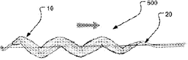
Figure 11 a and Figure 11 b are the side views of an embodiment of a medical locking device;
Figure 12 is the side view of an embodiment of a medical locking device;
Figure 13 a, 14a, 15a, Figure 13 b, 14b, 15b and Figure 13 c, 14c, 15c be respectively the supply shape through extending, one through expansible shape with two side views and the sectional elevation of another the medical locking device when being inserted in the perforate in chamber in vivo.
The specific embodiment
Now with reference to the accompanying drawings the specific embodiment of the present invention is elaborated.Yet the present invention can specifically implement and should not be interpreted into these embodiment that only limit to be illustrated at this with many different forms, but should be understood that it is intactly to disclose and fully inform those skilled in the art's scope of invention for clear that these embodiment are provided.The term that is used for the detailed description of the embodiment shown in the accompanying drawing is not to limit meaning the present invention.Same in the accompanying drawings label is meant same element.
Below explanation concentrates on some embodiments of the present invention, these embodiment can be applied in the intracoelomic cavity of blood vessel form, be the side branch vessel that goes out by a main vascular bifurcation or other perforates in blood vessel specifically, breach or enter aneurysmal perforate for example.Yet, should recognize that the present invention is not limited to this application but can be applied to for example being included in central nervous system, gastrointestinal tract, respiratory apparatus system, urinary organs system and the intrasystem inner chamber of heart in many other intracoelomic cavities.In addition, weak internal chamber wall, for example the wall of the preceding aortic aneurysm of breaking in stage is another field that medical treatment device of the present invention is used in early days.
In one embodiment of the present of invention of Fig. 1, a medical treatment device 1 is shown.This medical treatment device is suitable for interim inaccessible fluid flow from branch's inner chamber 90 that a main inner chamber 80 of health flows on the intravital crotch of this body, perhaps closed perforate or the weak part 85 that centers on the another kind of form on tissue wall 81 of this inner chamber.Main inner chamber 80 has a tissue wall 81, and branch's inner chamber 90 has a tissue wall 91.The perforate 85 that branch's inner chamber 90 enters main inner chamber 80 is called as the aperture.Described health is human body or animal health, for example a kind of mammiferous health.
This medical treatment device is can fold with expansible, is used to run through inner chamber and supplies with crotch 100 or supplied with by crotch.Display device 1 is in swelling state in Fig. 1, and this device is unfolded and release is mounted with a supplying duct, and is positioned on branch's inner chamber 90 and can prevents that fluid is from main inner chamber 80 inflow side branch inner chambers 90.Yet this device 1 remains fixed on this feed unit by an one metal wire 25.That mean this side branch inner chamber 90 and this main inner chamber 80 not fluid be communicated with.Fluid is by the circulation or mobile the getting clogged of this aperture approaching side branch inner chamber.This realizes in an efficient way.The location is to carry out according to the therapy that practitioner is known, and will be further specified below this.
This medical treatment device 1 comprises an aggregation of one first an expandable balloon 10 and a bracing or strutting arrangement 20.First balloon 10 has a longitudinal size that extends between a proximal part 11 and a distal portions 12.This first balloon 10 comprises that when balloon 10 is in as shown in Figure 1 the state that is inflated this first balloon 10 comprises an inwall 15 and a radial outer wall 16 of radially arranging on a mutual radial distance.When folding state, or balloon 10 is not when being inflated, except inwall 15 these outer walls 16 also adjacent to this supporting construction.When first balloon is in the state that is inflated, inwall 15 around or surround an internal cavity 19, this internal cavity 19 is configured to can be by this internal cavity 19 one fluid flow passages longitudinally, illustrated a kind of like this flowing of arrow among for example visible Fig. 4.First balloon 10 can be inflated by one or more inflation lumen 17.
This set comprises at least one supporting construction 20.This supporting construction 20 is illustrated as a tube-like piece in Fig. 1.The medical treatment device of some embodiment comprises at least one folding and expandable supporting construction 20, longitudinally is disposed between the near-end 11 of balloon 10 and the far-end 12 and radially is arranged on the inwall 15 of balloon to small part.Figure 11 b is for example seen at the two ends 11,12 that supporting construction 20 also can expand and exceed balloon.Supporting construction 20 supports the internal cavity 19 of an opening of first balloon 10 that is in swelling state when being in swelling state.
So just can obtain a plurality of advantages.First balloon 10 is dashed forward with a kind of needed primary circle or cyclic shape is fully kept, and does not rely on the environmental aspect of dissection.And the permission fluid by this aggregation is kept reliably at the flow through path of first balloon 10 of bifurcation.For example shrink by vascular or fluid at the sealing effectiveness that can't influence this aggregation that moves of the body on this bifurcation 100 that TRANSFER BY PULSATING FLOW produced of main inner chamber 80, and in the perforate of branch vessel, keep and cut off circulation.
Supporting construction 20 also this aggregation is positioned in inner chamber and when being inflated the elasticity of the wall of inner chamber a counteracting force is provided.In addition, this supporting construction provides the counteracting force that moves inward to balloon inwall 15, thereby this inner chamber is opened to big degree, and this just allows balloon 10 cushions to have low profile with respect to the whole diameter of intracoelomic cavity.Like this, the effect inwardly because balloon is extruded between this vascular, and this supporting construction just can be provided at the reliable fixed location in this inner chamber as opposite points and/or effect outwardly.
This power that is provided by supporting construction 20 can be improved the sealing on tissue wall effectively in addition.And the tissue of internal chamber wall is disposed lightly and can not be damaged.Have the inherent toughness of the prominent shape inner chamber of its unfolded gently circle through expansible balloon 10, this cushion effect allows advantageously and places internal chamber wall.
The bulbs of pressure of first balloon may be selected to balloon be inflated can provide through expansible balloon between supporting construction and inner chamber the cushion effect.Expand to such an extent that make on this wall and to produce damage even first balloon 10 does not expand into such degree internal chamber wall.The bulbs of pressure provide promptly feasible like this can provide reliable sealing, and sealing can for example provide fluoroscopy and suitable contrast media to check in real time.The size of these bulbs of pressure is to be lower than that to be used for traditional angioplasty balloon needed.Also have, this device can be maintained at reliably on the correct position and do not washed out.Can be allowed to by expansion to a certain degree through this tissue wall 81 that expansible aggregation produced.
The outer wall 16 of first balloon is designed at least in part and is placed on the inwall 81 of main inner chamber 80 of this branch's side 100.As shown in fig. 1, outer wall is contiguous and away from 85 ground, aperture and place on 80 the inwall of main inner chamber.
In another embodiment, as shown in Figure 5, the outside that whole outer wall or its at least directly make progress can be juxtaposed to main inner chamber 80 inner tissue's wall surfaces.This radial outside can be straight substantially on the longitudinal extension of balloon 10.
By this way, when device 1 launched and is inflated and launches on this bifurcation 100, the fluid passage by main inner chamber 80 can keep unimpeded and the circulation that for example enters the fluid passage of branch's inner chamber 90 by perforate is fully sealed.Simultaneously, this device is owing to prop up the wall of inner chamber reliably and for example one supply with tinsel, conduit etc. and stablized by remaining fixed in feed system in the bifurcation of main inner chamber 80.
When this installed a given suitable longitudinal size, it can a plurality of perforate of style thereby can inaccessible enter flowing of these perforates.If the end cap perforate is positioned on the diverse location radially and longitudinally of inner chamber, this may be favourable.In addition, vulnerable at this internal chamber wall, for example have the disruptive risk of internal chamber wall, internal chamber wall dies down or or during the situation of a plurality of less perforates, by some embodiments of the present invention, comprise that some devices with long longitudinal extension or example as shown in FIG. 5 with reference to the described some other embodiment of Fig. 5, can advantageously seal these situations.This balloon has the long longitudinal extension length greater than the perforate of tissue wall 81 or the place that dies down.
When being inflated, this inwall 15 and outer wall 16 are that coaxial line ground is arranged relative to one another, are that middle heart is arranged in the inwall 15 fortunately in the supporting construction 19 and give internal cavity 19.Further, this supporting construction 20 is piped supporting constructions, includes the common cylinder of arranging facing to cavity central authorities 19 on the inwall border of first balloon 10.This supporting construction 20 on the inner boundary of first balloon 10 with first balloon, 10 coaxial lines be disposed in this cavity central authorities 19.
But this supporting construction 20 can be self-expanding.In these embodiments, this supporting construction is to be constrained in the process that for example feeds to bifurcation or perforate by a catheter sheath 44 (Fig. 4) to expand.When this aggregation for example discharges from withdrawing by withdrawal pipe sheath 44, but the supporting construction 20 of being somebody's turn to do self-expanding just radially expands with first balloon 10 that is being inflated, first balloon is inflated and this aggregation is positioned in the perforate 85 thus, for example as shown in fig. 1.
The diameter through self-expanding, d/d or natural of this supporting construction 20 is diameters of the inwall 15 when being in lax or natural diameter greater than balloon when being inflated with the essential bulbs of pressure, to obtain the positiver sealing of perforate 85.This supporting construction 20 through diameter self-expanding, lax or nature in addition can be greater than the diameter of outer wall 16 or the natural diameter of inner chamber 80.By this way, in the process of the temporary sealing of perforate 85, just permanently there is an orientation force 151 outwardly.
The expansible state of this aggregation is shown on the cross section of Figure 10 a.
This supporting construction 20 can be by suitable fixed cell, and for example glue, screw thread, tightening member etc. are fixed on the inwall 15.Support fastening can also being provided dividually, and be fixed to releasedly on first balloon in the directional expansion power of d/d state by the radial outward that works with first balloon.
In further embodiments, but supporting construction 20 be not self-expanding and need for example be inflated a swelling state 20a by an expansion cell by a feed unit.Supporting construction 20 for example is expandable balloon and/or can expands by other active expansion cell.
For this purpose, for example provide one second balloon 30, this second balloon is suitable for making this piped supporting construction 20 to expand, and is arranged in internal cavity 19 inside of first balloon 10 at least in part.Second balloon 30 is longitudinally to extend between the near-end of supporting construction 20 and far-end at least, and whole supporting construction 20 is inflated when expanding so that be at second balloon 30, sees Fig. 2.
Expansion for two balloons provides inflation lumen.First inflation lumen 17 is related with first balloon 10, and second expanding baloon 37 is related with second balloon 30.
Fig. 3 is a sectional elevation in a longitudinal direction of medical locking device 1, shows the inflation lumen 17 of stretching out from a catheter shaft 45 among the figure.Support net thing 18 be made for supporting construction 20 is connected on the catheter shaft 45 or the supply tinsel of central authorities and/or active expansion cell on.This support net thing can be arranged to the support net thing 18 of guiding.It is whole that support net thing 18 can become with supporting construction, for example becomes integral body with twine, can optionally vertically stretch out balloon 10, as shown in Figure 11 b or Figure 12.In addition, can and on the tail end of medical treatment device 1, provide another net in the inside of internal cavity 19.The support net thing 18 of guiding helps to make medical treatment device 1 folding again it insertion in this sheath 44 from bifurcation 100 medical treatment device extracted out and to be pulled out external.This net can constitute a filter element, is used for when aggregation is in appropriate location in the perforate 85 the fluid main inner chamber 80 of flowing through.This filter element can be a clot filter.Filtering degree is to be determined by a number radial and/or net longitudinally of the selection of fabric and location or supporting construction 20.
The net of hangover helps aggregation is inserted in the conduit, and this aggregation can automatically fold in an immediate perforate that is pushed into conduit cavity the time.
First and second inflation lumen 17,37 can be arranged to fluid flow each other.In these embodiments, first and second balloons both time expand and to be provided.This can easily be installed in medical treatment device 1 on the bifurcation 100.The healthcare givers only should be noted that one expansion step, just can make medical treatment device safety location.
This first and second inflation lumen 17,37 does not circulate each other in another embodiment.The single expansion of first and second balloons is provided.This embodiment be used in some dissect in situations more satisfactory, wherein for example when supporting construction is not self-expanding the initial alignment of device be by making the realizations of expanding of first balloon 10.Then, second balloon 30 is inflated so that supporting construction 20 expands, thereby medical treatment device 1 is fixing safely and provide support to internal cavity 19 for fluid flow, and to perforate 85 sealings.Further, second balloon 30 can be drawn out of subsequently, just stays the next large diameter inner chamber of opening by aggregation for fluid flow.This uses useful especially to high flow rate, for example close heart output to keep the output of heart.
Owing to be arranged in the internal cavity 19 of this first balloon 10, even the internal cavity 39 of second balloon also provides a path of crossing by the longitudinal stream of medical treatment device 1 when medical treatment device 1 is positioned in bifurcation 100 first balloon 10 and second balloon, 30 coaxial lines.
In certain embodiments, supporting construction 20 is attached to the inwall 15 of first balloon 10 at least on the outside wall top of the inwall 15 at internal cavity 19 places.
Alternatively, supporting construction 20 is attached on the inner wall surface thereof in first balloon on the inwall 15 of first balloon 10.
Supporting construction 20 when being inflated, when being in expansion counteracting force with inwall 15 balancing each other under first balloon, 10 expansible situations, will be in common radial position.
By an expansion cell during by the situation of the configuration after expanding into it from the unfolding configuration effectively and expanding, this contractile sheath can be omitted in supporting construction.Constraint in the configuration of supporting construction 20 after it is folding is optional.
For example, this expansion cell can comprise one be arranged to suitably to make can not self-expanding expansible effectively propeller of supporting construction 20 or propulsive sheath.This expansion cell can comprise that several arms or one can flexibly expansible structures, it is inner towards the configuration of opening that is extrapolated to after the expansion from it that they can promote supporting construction 20, and wherein this configuration supports first balloon and several effects described herein and function are provided.
This expansion cell can be the second above-mentioned balloon 30.
In addition, first balloon 10 can support the expansion of this supporting construction 20 in the process that it is inflated.
First balloon has the bulbs of pressure of a maximum, and this will be illustrated with reference to Figure 10 a below.This maximum swelling pressure is lower than the burst pressure of balloon 10 suitably.This first balloon 10 is being positioned at this body place and/or at least in whole obturation/in the sealing stage, be to be inflated a pressure that is lower than this maximum swelling pressure.Like this, first balloon 10 just can be positioned in interior intracavity with organizing especially affinely.The balloon 10 that partly is inflated is juxtaposed to the balloon structural cushion effect of wall of expansible inner chamber therein with especially being provided for particularly soft.
Supporting construction 20 after this expansion is configured to bear the direction of balloon after expansion active force inwardly in certain embodiments.Like this, the expansion outwardly of first balloon is guaranteed, can prevent that balloon is inhaled in this perforate 85 simultaneously.To taking place when the balance, see Figure 10 a than the radial elastic to a certain degree of minor diameter.
In the time of obturation, supporting construction 20 can be a kind of when being inflated it is locked releasedly through expansible configuration.This can for example be provided by an interlock or identical mechanism.Supporting construction least energy (through folding and through expanding) 2 between bistable state selectively or except that lock function be provided.
Supporting construction 20 can be a tubular structure that comprises mesh wiry.Selectively, or in addition, it comprises the style of pillar and adapter, for example one as stretch (stent) technology as can be known zigzag style from exhibition.
A kind of stretched out structure comprises a cylindrical frame, and this cylindrical frame is curled up by a series of spiral types that contain the pattern of alternative zigzag bending to be formed.This framework can be to constitute by elastic tinsel or by the part of the subcutaneous injection pipe of cut.
For example, disclosed a kind of method of making this stretched out structure in No. 6572647, United States Patent (USP) US, the content of its announcement is incorporated herein in the lump.This stretched out structure that is used to run through the cut that inner chamber supplies with has several windows on its cylindrical wall, and these windows are giving the pliability that stretched out structure is improved when described inner chamber is supplied with.The method of making a kind of like this stretched out structure comprise from the wall of a pipe remove enough materials with stay with various line of cut that separates by a kind of allow tube expansion the tube wall that penetrates of pattern.This pipe is inflated subsequently, following a plurality of tube wall fritter parts is removed from the tube wall between adjacent line of cut, introduce a plurality of intervals between the adjacent spreading area of tube wall surface thus, the structure of these reservations allows to be pushed to along a zigzag intracoelomic cavity after pipe is compressed to a kind of configuration advances.Advantageously, the material of this pipe is the stretching, extension that a kind of marmem and this pipe are used for self-expanding.
Yet the outside that the structure of stretching, extension always is positioned in an expandable balloon up to now is used for expanding and permanent the implantation.Stretched out structure is designed to and places vascular tissue.Compare, supporting construction 20 of the present invention is designed to and puts on the balloon inwall, to support balloon and have the prominent sealing gasket of a circle between supporting construction 20 and inner chamber interior wall tissue.
Selectively, or except a tubular structure, this supporting construction can comprise a plurality of additional or optionally facing to the radial support silk screen at the tubular structure of this announcement.Silk screen 18 is arranged from a catheter shaft 45 or a supply tinsel.Twine 18 can be for example by the orientation force of pretension with the radial outward that provides support first balloon on bifurcation 100.
The length of the length of supporting construction 20 and second balloon 30 if be arranged wherein, is the length greater than the longitudinal size of first balloon 10 in one embodiment.This illustrates in Fig. 6 and Figure 11 b, and wherein supporting construction 20 vertically stretches out 21,22 as shown in the figure.
Another example is the obturation of aneurysm 910, as shown in Figure 8.With a kind of top, stop fluid flow or stop flowing into this aneurysm from main inner chamber with reference to the described similar fashion of Fig. 6.Here, aneurysm is not also broken, and blood vessel wall is perfect but it is weak to have become.Can make pressure relieve by interim cut-out locking device 200.
This perforate or undesired perforate be normally side perforate on internal chamber wall in the application's full text.
With reference to Fig. 6, can see that the near-end of supporting construction 20 and/or far-end are to be configured to it to may expand to a bigger external diameter greater than the internal diameter of the internal cavity 19 of first balloon 10.
Stretching out on the near-end of supporting construction 20 and/or far-end 21,22 can be that outer wall towards first balloon 10 outwards expands and the orientation is respectively away from this near-end and/or far-end.By this way, provide the fluid guiding, this advantageously makes the fluidic disturbance of the medical treatment device of flowing through in main inner chamber 80 be reduced to bottom line.And sealing improves.
Like this, this medical treatment device 1 is provided with a supporting construction 20 and comprises that at least one nearside stretches out the near-end 11 that 21 contiguous ground longitudinal extensions exceed first balloon 10.This nearside stretches out 21 can comprise that a cover layer or fluid tight layer or coat are used for to organize affine mode and inner tissue's wall of the main inner chamber 80 of contiguous first balloon 10 to contact with each other.Like this, stretch out 21 when expanding, the fluid guiding in a kind of internal cavity 19 that enters first balloon 10 just is provided at supporting construction 20 and its nearside.
This supporting construction 20 comprises that in several embodiment a distally that vertically remotely extends beyond the far-end of this first balloon stretches out 22.This distally is stretched out and can be comprised that a cover layer or fluid tight layer or coat are used for to organize affine mode and inner tissue's wall away from the main inner chamber 80 of first balloon 10 to contact with each other, make like this and stretch out 22 in supporting construction 20 and distally thereof when expanding, provide a kind of fluid that flows out and/or enter the internal cavity of first balloon to guide.
One or morely stretch out 21,22 and can be made for a sealing flange.The sealing flange can be made by suitable fabric.
Vertically stretching out of supporting construction 20 can have a heat fixation shape facing to an extension of the external diameter of first balloon.The longitudinal extension of supporting construction is big equally with the diameter of perforate 85 at least.By this way, guiding of this fluid and the tissue that stretches out and place main in cavity wall just particularly advantageously be provided at the fluid-tight seal on the perforate and the cut-out of circulation.The obturation of the fluid flow of approaching side branch inner chamber 90 is provided effectively.
In this embodiment, first balloon has the balloon body of the prominent shape of a long circle when being inflated.
The outer wall 15 of first balloon 10 partial design at least becomes to be used for soft tissue is juxtaposed to main inner chamber 80 in the first of this outer wall inwall, and this device just disposes safely and combines with this main inner chamber hermetically like this.This outer wall is more satisfactory to be to be capped thin layer, so that it is juxtaposed on the tissue wall to organize affine mode.
The outer wall 16 of first balloon 10 and inwall 15 can have several parts of different hardness.Different hardness for example is that the different wall thickness by several parts of outer wall and inwall provides.The outer wall 16 of first balloon 10 for example has near-end and distal portions, and they have one greater than the wall thickness in the central microscler part wall thickness of outer wall 16.Thicker part can advantageously be oriented to towards perforate at the state of being supplied to.By this way, medical treatment device 1 is cut off reliably by the vertical passage of the opening of main inner chamber 80, thereby the obturation of side branch vessel 90 is provided.
The maximum outside diameter of first balloon 10 is in 40% to 90% scope with respect to the ratio of the path intracavity diameter that the quilt of internal cavity 19 is kept.This ratio value can be 75% to 90%, for example 80%, 85% or 90%.Because the expansible naturally diameter of supporting construction 20 is the expansible naturally internal diameters greater than balloon 10, so high ratio is possible.
Medical treatment device 1 can comprise the radioprotective labelling.Selectively, or in addition, first balloon 10 is suitable for being inflated with radiation proof material.This helps when fluoroscopy medical treatment device 1 being positioned at bifurcation 100.
This inner chamber is a blood vessel in some specific embodiments.Outer wall 15 is configured to be positioned to the aperture that sealing covers the branch's inner chamber 90 on this bifurcation 100.
The aggregation of first balloon 10 and supporting construction 20 can fold after expansion again, makes device can run through inner chamber like this in the time of inaccessible this branch's inner chamber 90 and removes and take out health from bifurcation.
As shown in FIG. 6, the external diameter of first balloon 10 can be selected to the internal diameter that is slightly larger than main inner chamber 80.In this way, just can provide the reliable location of medical treatment device 1 in main inner chamber 80, and not injure what tissue of no longer holding the post.
Figure 10 a is a sectional elevation by a medical locking device of an occlusion in body cavity.The various power that act on during swelling state at aggregation in the time of on being positioned in a perforate 85 are represented with arrow 150-153 in the drawings.
One first power 150 radial inward effects and be that pressurized inwall 15 by balloon 10 is produced.One second this first power 150 of power 151 balances that expansive force produced by supporting construction 20.This supporting construction is not to be inflated fully.
But in supporting construction is the situation of self-expanding, and this supporting construction 20 is greater than balloon 10 internal diameter on inwall 15 when expanding at its external diameter that discharges relaxed state, and adiaphorous equilibrant.
When but this supporting construction obturation was not self-expanding, this state can be provided with the whole bag of tricks.For example, a metal wire frame can be expanded effectively, and the interior balloon with himself path can be inflated in this inner chamber 80, and net flexibly radial inward promotes inwall 15, or the like.
A position that may arrive when dotted line 20a illustrates this structure 20 and do not have equilibrant being inflated fully.
The direction of supporting construction 20 expansive force 151 outwardly is greater than the inside expansive force 150 of direction.This supporting construction 20 can abut against on the wall 15 and can not fix on it like this, can relatively move to allow two walls respect to one another, thus owing to active force reduces to help to launch, expands and recovers.
This medical treatment device 1 can be contained in the medical system 2, and branch's inner chamber 90 that this medical system 2 is designed to the main inner chamber 80 of interim closed one enters the branch's inner chamber 90 on the bifurcation 100 in vivo.This system comprises, as Fig. 4,5 and 11a shown in, a conduit 40 comprises a catheter shaft 45 and a catheter sheath 44 at least one medical treatment device 1.The aggregation of medical treatment device 1 is interrelated with catheter shaft on the distal portions of catheter shaft 45.It is the expansion that retrains this aggregation in aggregation is positioned in catheter sheath the time that this catheter sheath 44 is arranged.Catheter sheath 44 is to expand with this side branch vessel of temporary protection in bifurcation 100 to allow aggregation from catheter shaft 45 withdrawals.
This catheter shaft 45 comprises a guide wire lumen of passing through for lead 46 conduit 40 being positioned in this main blood vessel 80 on the bifurcation 100, and at least one inflation lumen is used for expanding and gives first balloon 10 at least.This system 2 also comprises the lead 46 in the guide wire lumen that is disposed in catheter shaft 45.
The material of making balloon can be polrvinyl chloride (PVe), crosslinked polyethylene (PE), polyester (PET), poly-to benzene first diacid glycol ester, nylon and other.Specifically, polytetrafluoroethylene PTFE as the product G oretex that can buy, is suitable as the material of balloon.
This medical treatment device mainly is used in the arteries operation of passing through fluoroscopic examination vision facilities (blended OR) in operating room in certain embodiments.This medical treatment device can be used in acute and the elective operation.
At the operative treatment of some organ, in for example acute operation process, requirement has the cut-out of control to flow into the blood flow of area for treatment.In addition, in the operation process of plan, can require the flow through fluid of the perforate in the inner chamber of the cut-out of control as the part of operating procedure.For example, in a kind of passive peripheral blood vessel was interfered, as an initial step of interfering, this medical treatment device can be positioned in this periphery blood vessel.
This device is useful for passive interference in some operation like this, and this does not need acute measure.
Fig. 9 a and Fig. 9 b are the schematic illustration of medical locking device that has the above-mentioned form of an one-way flow direction unit 800 in internal cavity.By this one-way flow direction unit 800, this medical treatment device is provided with non-return valve function.
In this embodiment shown in Figure 9, a plurality of valve blocks 801,802 provide this non-return valve function.In other embodiments, this one-way flow direction unit 800 can comprise one valve block, for example the valve block with the central fixed circle on lead or catheter shaft 45.
Valve seat is set on the structure of separating.For example the valve seat annular ring of charging in the internal cavity that can be used as supporting construction 20 is set up.
Self-expanding or the expandable valve assembly that runs through conduit of balloon can be positioned in the inside of this supporting construction 20.
Selectively, or in addition, this supporting construction 20 can be an exterior portion that is used to run through the valve assembly that conduit supplies with.The improvement valve that this one-way flow direction unit 800 can be a kind of little intrusion heart valve membranous type that for example discloses in the US6454799 United States Patent (USP) of Edwards Lifesciences, the reparation valve that is used to run through the inner chamber supply that for example in the US7018406 United States Patent (USP) of Corvalve company limited, discloses.These disclosure are incorporated herein in the lump.In an embodiment of the present invention, these nonvolatil valve assemblies of being familiar with for everybody suitably are improved to structure that can fold again and that centered on by a dilatable balloon 10 of the present invention.
A kind of have one-way flow direction unit 800 and expandable balloon 10 that centers on and inter-related supporting construction 20 like this, just are provided.Some application examples of a kind of medical treatment device like this are therapy in this way, wherein requires interim a kind of interim one-way flow that produces.This medical treatment device can provide one on this internal chamber wall abnormal perforate obturation simultaneously.
An example that is used for a kind of like this therapy comprises this medical treatment device is positioned at this Venous system.For example, this medical treatment device can be positioned on the vein breach in this Venous system.A vein breach for example may occur in veins periphery or central authorities, thereby needs medical treatment.
Another example is interim valvular arrangement.
A kind ofly medical treatment device 1 is deployed in method on the bifurcation 100, will further provides below by aforesaid medical system 2.Other perforates that are positioned at except that facing toward the aperture of branch vessel also are correspondingly to carry out.
A medical treatment device with oval cross section is shown in Figure 10 b.Here, also provide a kind of along the volumetrical fluid flow between outer wall 16 and internal chamber wall shown in the hacures cross section among the figure.
Device provides its reliable sealing with respect to the radial location of perforate/weakness 85, and adopts a plurality of fluid passages to increase the fluid flow of potential maximum.In addition, because redundant flow channel is provided, just can reduce the risk of the obstruction of fluid flow in the main channel.And under the main inner chamber that wherein feed unit middle ground layout and net or inflation lumen are radially extended was compared, this additional flow channel 80a was unrestricted.
A kind of kit utility 3 comprises the medical treatment device 1 of at least two above-mentioned forms.As shown in Figure 5, the medical treatment device 1b of the medical treatment device 1a of a near-end and a far-end is comprised in the kit utility 3.This medical treatment device 1a, 1b is spaced from each other and interconnect by revealing sealing interconnecting unit 50 by a fluid of fluid flow between the internal cavity of first balloon that is suitable for medical treatment device 1a, 1b.This interconnecting unit can extend through the one or more perforate on internal chamber wall.
In this embodiment, this interconnecting unit 50 is piped interconnecting units, has one at the near-end of this piped interconnecting unit and the tubular wall 51 of the fluid-tight between the far-end.This tubular wall can be to be made by a kind of diaphragm material.Suitable material comprises polytetrafluoroethylene PTFE, can buy as the GoreTex product.Selectively, or in addition, can provide the graft material that is reinforced.By this way, this unit 50 is suitable for standing exceeding the radially outer expansion of the tubular form of desired maximum gauge.。This diameter for example is the external diameter of this balloon 10, or the internal diameter of the nature of main body inner chamber.
The near-end of tubular wall 51 is connected in the far-end perforate of internal cavity 19 of the medical treatment device 1a of near-end.The far-end of tubular wall 51 is connected in the near-end perforate of internal cavity of the medical treatment device 1b of far-end.A fluid passage between the internal cavity of two medical treatment device 1a, 1b is provided.This medical treatment device 1a, 1b when its first balloon expansion, provide near its fluid-tight location of the inwall of main inner chamber and only allow fluid to flow to its internal cavity.Because internal cavity interconnects each other by this tubular wall 51, just can prevent effectively that fluid from flowing in perforate 85 or the branch vessel 90.
This tubular interconnection unit can have other is not circular cross section, for example oval, flat, orthogonal, or the like.
The medical treatment device 1a of this near-end is suitable for being positioned near the aperture of the branch's inner chamber that enters main inner chamber.The medical treatment device 1b of this far-end is suitable for arranging along this aperture in this main inner chamber.It is more satisfactory to be that to be disposed in a distance leaving this aperture last, and can not contact tissue, aperture or branch's inner chamber of this main inner chamber, as shown in Figure 5.The external diameter of tubular inner wall 51 is more satisfactory to be natural internal diameter less than intracoelomic cavity.Like this, just can avoid when removing medical treatment device, producing the fragment or the residual grain that may be poured branch vessel.
Now turn to Fig. 7, a kind of interim obturation be will be described in the method 7 of the fluid flow of branch's inner chamber of this intravital bifurcation below by the main inner chamber inflow of body.This method can be carried out with similar method on other perforates except the aperture of described branch vessel or structure organization wall weakness.
This is used for interim inaccessible main inner chamber inflow by body and comprises in the method 7 of the fluid flow of branch's inner chamber of this intravital bifurcation:
Running through inner chamber will be fed to bifurcation 710 with the medical locking device of folded state, and
To the one first expandable balloon expansion 720 of small part, and make a supporting construction expansion that this medical treatment locking device is expanded in bifurcation, like this by the medical locking device between an one near-end and a far-end
The outer wall that makes first balloon is to small part and put 730 on the inwall of main inner chamber on the bifurcation, and
It is unimpeded 740 that the path of the fluid that makes intracavity in main by the internal cavity of the first expandable balloon of the inside of an one inwall keeps, like this
When this medical treatment locking device fully seals the 750 fluidic paths that fall into into this branch's inner chamber when bifurcation is launched, and provide fluid flow longitudinally, and behind one section off-period, run through inner chamber from bifurcation this medical locking device that is folded once more of withdrawing by this internal cavity.
Further, this method is included on the inwall of first balloon longitudinally at least partially in radially making a supporting construction expand 760 between the near-end of first balloon and the far-end, like this by the internal cavity of an opening of this support construction supports.This step that expands 760 supporting constructions comprises making to small part and is arranged in one second balloon expansion in internal cavity and the supporting construction, and makes this supporting construction 770 to diameters less than main intracavity diameter that expand.Selectively, or in addition, this expansion step 760 comprise by one based on the tinsel of conduit by the near-end of conduit this supporting construction that controllably expands.
The expansion of supporting construction proceeds to the internal diameter after expanding normally that its diameter surpasses balloon, like this, the inwall radial outward of balloon is expanded.
This comprises the step 720 of first balloon expansion to make this first balloon expansion to diameter greater than the internal diameter of main inner chamber.
This supplying step 710 and withdrawal are to adopt a kind of seldinger technique and fluoroscopy of standard to finish.As adopting flexible programs more according to the present invention to be used the safety that this can make system's user feel affine and increase the patient because of a good clinical method that is established.
This first and second balloon can be inflated simultaneously by a common inflation lumen.Selectively, this first and second balloon can be inflated independently by the inflation lumen of separating.
This first balloon and subsequently this second balloon can one after the other be inflated.
In one embodiment, this method comprises at least two medical locking devices is positioned at this bifurcation spaced apart from each other, and it is interconnection with these medical treatment devices to reveal the sealing interconnecting unit by a suitable fluid, is provided at the fluid flow between the internal cavity of first balloon of medical treatment device like this.
This method comprises the circulation of this unitary fluid passage of tubular interconnection that the tubular wall of fluid by have a fluid-tight between unitary near-end of a tubular interconnection and far-end is provided, wherein the near-end of this tubular wall is connected in the far-end perforate of internal cavity of the near-end of medical treatment device, and wherein the far-end of this tubular wall is the near-end perforate of internal cavity that is connected in the far-end of this medical treatment device, so that be provided at a fluid passage between two internal cavities.
This with at least two medical locking devices be positioned at the step of bifurcation spaced apart from each other, comprise that in this embodiment the medical locking device with a near-end in these at least two the medical locking devices is positioned near the aperture of the branch's inner chamber that enters main inner chamber, and the medical locking device of a far-end of two medical treatment devices is positioned at the far-end in this aperture, and along this aperture this tubular wall is arranged in main in intracavity, leaving on the distance in this aperture, and do not contacting tissue, aperture or branch's inner chamber of main inner chamber.
In one embodiment, this inner chamber is a blood vessel, and this method is included in the portion of time in inaccessible stage and is carried out surgical operation by side branch inner chamber by the organ of blood supply to one.
Figure 11 a and 11b are the side views of an embodiment of a medical locking device.The conduit 40 that has a sheath 44 in Figure 11 a is illustrated, and has the aggregation of a supporting construction 20 and a balloon 10.This stretched out structure 20 is installed in two and stretches out on the structure.In addition, having a balloon that stretches out line 10 that separates preferably is installed on this stretched out structure.Figure 11 a shows the conduit 40 of the sheath 44 that has a weak point.Figure 11 b illustrates the end portion of this assembly.This stretched out structure and balloon show it is to be in to be inflated and open state in the drawings.
By this first is stretched out structure 310 and be pushed forward at second of conduit 40 near-ends and stretch out structure 320, this stretched out structure 20 is stretched.Be installed in second and stretch out on the Luer latch fitting of the moon of structure 320 by being screwed at the first Luer latch fitting 330 that stretches out the sun on the structure 310.Lead is inserted into guide wire lumen as the tinsel that supports, and promptly this second stretches out in the structure 320.
This stretched out structure 20 and balloon 10 can be pulled back in this sheath end then.Balloon 10 can be coated on stretched out structure 20 around stretched out structure 20 is withdrawn in the sheath 44 by moving whole stretching out on the structure 310,320 together to.
Now prepare conduit 40 is inserted in this body.
For the aggregation that makes balloon and stretched out structure expands, stretch out structure 310,320 and push this stretched out structure is advanced by distinguishing 2.In case this stretched out structure 20 is in the tram, these Luer latch fitting 330 releases are so that stretched out structure 20 expansions.
Inject for example air or saline by balloon 10, the side arm of blood vessel gets clogged.The maximum swelling volume that is pressed into balloon is that be defined by being no more than can balloon shooting or the threshold value of folding this stretched out structure in advance.Otherwise this blood vessel can get clogged.
Figure 12 is the side view of an embodiment of a medical locking device.Can for example provide effective expansion by the operated one metal wire 45 of the near-end that is used as the conduit of supplying with medical treatment device, and this this tinsel is fixed on the catheter sheath at least one point by relatively moving of the relative catheter sheath of supporting construction.It is an example that a tinsel screen frame that is activated by central authorities' control tinsel is expanded, and is used for a kind of like this tinsel operation of determining the degrees of expansion of this supporting construction, as above described like that with reference to Figure 11 b.
The aggregation 400 of balloon and supporting construction is elongated and folds by promote to supply with tinsel at far-end.By discharging this supply tinsel, this aggregation is because the elasticity of supporting construction just expand into its natural form.From this natural releasing pattern of this aggregation, this supply tinsel is further to be drawn back relatively moving of conduit, like this, further make this aggregation on internal chamber wall perforate or the intracoelomic cavity of weakness in radially expand.This balloon just is inflated subsequently as described above.
The end of this balloon is cut into an oblique angle to help to insert this conduit and to insert in the conduit again when regaining.
This balloon is to be made by two thin slices that are welded to one another on the edge.
This locking device neither is released also from this conduit and does not discharge from this feed unit; It all remains secured to conduit or feed unit at any time.
This device is positioned in this perforate and is released from conduit in this position subsequently, and be inflated and and launch to put in place, need not further vertically to relocate.This catheter sheath can for example be regained in this position.
Figure 13 a, 13b, 13c be another medical locking device 500 be in respectively one after the expansion supply shape, an expansible shape and be inserted in two side views and a sectional elevation in the perforate of intracoelomic cavity.
(Figure 13 a) enters into by move a scope line 501 formed expansible spiral in shape in Figure 13 a direction of arrow this device 500 from relaxed state.
In the time of on for example being positioned in this aperture of side inner chamber, this perforate gets clogged.
Present embodiment has a little diameter after folding, and especially can be fed to this tapping by narrow supply passageway.
Replace balloon 10, can use a kind of soft, spongiform structure.This structure can be in it begins to contact expands during the body inner fluid of intracavity, thereby has improved sealing effectiveness.
Figure 14 a, 14b, 14c are that another medical locking device 600 is in one respectively through expansible supply shape, an inflated configuration be inserted in two side views and a sectional elevation in the perforate of intracoelomic cavity.
This device 600 if trachea design and just supply condition (Figure 14 a) promotes state after scope line 501 enters expansion by the direction of arrow in Figure 14 a.
When in this perforate that is positioned in side inner chamber for example,, just can prevent to flow into this perforate because the whole device 600 that flows through after this expansion is transferred.
Replace balloon, a kind of fabric construction of fluid-tight can be provided.Present embodiment has extra high circulation because the near-end of fabric construction has and the same diameter of far-end (its orientation is against flow direction).This far-end has a cushion or expandable balloon to improve sealing.
Figure 15 a, 15b, 15c are that another medical locking device 700 is in one respectively through expansible supply shape, an inflated configuration be inserted in two side views and a sectional elevation in the perforate of intracoelomic cavity.
(Figure 15 a) enters into by move a scope line 501 formed expansible spiral in shape in Figure 15 a direction of arrow this device 700 from relaxed state.
When in this perforate that is positioned in side inner chamber for example,, just can prevent to flow into this perforate because the whole device 600 that flows through after this expansion is transferred.
Replace balloon, a kind of fabric construction 610 of fluid-tight can be provided.
As adopting at this, " a " of singulative, " an " " the " are outer unless stated otherwise otherwise mean also and can comprise plural form.It is also understood that, " includes ", " comprises ", " including " and or " comprising " these terms in being used in this description the time, be determine to have feature, integral body, step, operation, element and/or the parts that are illustrated, do not exist or add one or more other feature, integral body, step, operation, element and/or its combination but do not repel.Be understandable that when an element was known as by " connect (connected) " or " coupling (coupled) " in other elements, it can directly be connected or be coupled to other element or can have insertion element therebetween.
Unless be defined in addition, use all terms (comprising technical term and scientific terminology) herein to have the identical implication of understanding jointly as by the those skilled in the art.Can also further understand, for example in the dictionary that is used jointly defined term should be interpreted into have with in full in the corresponding to implication of its implication in this correlation technique, and cannot Utopian or excessive formal understanding make an explanation, unless be defined especially like this at this.
Though described and illustrated several embodiments of the present invention at this, but the those of ordinary skill of being familiar with present technique can easily predict other different means and or structure carrying out function and/or to obtain result described herein and/or one or more advantage, and each such modification and/or change all be regarded as by the appended scope of the present invention that Patent right requirement limited in.
More generally, be familiar with the those of ordinary skill of present technique and can easily recognize, all parameter, size, material and structure described herein will depend on the concrete application or the application of teaching of the present invention.
The those of ordinary skill of being familiar with present technique can be recognized maybe can determine the means that only are to use conventional experience, specific embodiments of the invention many and described herein to be equal to.Therefore can be appreciated, aforesaid embodiment just illustrated by way of example, and is equal in claims with it in scope of means, the present invention can also except that as specifically be illustrated with content required for protection mode implemented.The present invention be directed to each the single feature, system, object, material, the kit utility that are illustrated at this, and/or method.In addition, if these features, system, object, material, kit utility and/or method be contradiction not mutually, any two or more such feature, system, object, material, kit utility and/or methods all are included in as by in the appended scope of the present invention that Patent right requirement limited.
Claims (60)
1. a medical treatment device (1), be suitable for providing sealing to the circulation that the main inner chamber (80) at an individuality enters between the perforate (85) on the wall (81) of this main inner chamber of a place (100) in this body temporarily, wherein said medical treatment device (1) comprises an induction system, nearly attached this induction system of adding of this device (1) is collapsible and inflatablely to run through the inner chamber supply to described place (100) and to comprise an aggregation:
A. one first expandable balloon (10), has a longitudinal size that fully extends between an one near-end and the far-end, when described first balloon is in when being inflated state at an inner radial wall (15) and the mutual radial distance of a radial outer wall (16), wherein said balloon described inwall (15) have a nature the open diameter in inside and around an internal cavity (19) with provide one by its internal cavity (19) along described main inner chamber (80) with by described perforate (85) fluid flow passages longitudinally, and ought be in the described first balloon outer wall (16) of this swelling state by certain part at least and put on the inwall (81) of the described main inner chamber (80) of described place (100); And
B. at least one collapsible and expandable supporting construction (20), has a diameter that is inflated, longitudinally be disposed between the described near-end and far-end of described first balloon (10), and radially be arranged on the described inwall (15), described thus supporting construction, when being in the state that is inflated, support at least at its described described first balloon of state (10) that is inflated with open described internal cavity (19);
The wherein said diameter that is inflated is greater than the open diameter in described inside, and described radial distance is less than the open diameter in described inside;
Thus, described device (1) fluid by described main inner chamber (80) when being deployed in described place (100) and fully keeping being unfolded unobstructed and hermetically cut-out do not have as for described device and to comprise that an agent delivery port enters described perforate (85) to carry certain agent by the circulation of described perforate (85).
2. medical treatment device according to claim 1 is arranged opposite to each other wherein said inwall (15) and outer wall (16) coaxial line, described internal cavity (19) be center arrangement in described inwall, and
Wherein said supporting construction (20) is a piped supporting construction, comprises that a common cylinder is to be disposed on the inwall border of described first balloon (10) to described cavity central authorities; And wherein said supporting construction and described first balloon (10) coaxial line be positioned in the described cavity central authorities on the described inwall border of described first balloon.
3. medical treatment device according to claim 1 and 2, wherein said supporting construction (20) but be self-expanding, and the described diameter that is inflated is a lax naturally diameter that is inflated, wherein said supporting construction (20) has one less than the described lax naturally diameter that is inflated when described first balloon (10) when opening, described thus supporting construction is can be by the orientation force of a radial outward of adaptation when described first balloon is opened.
4. medical treatment device according to claim 1 and 2 comprises second balloon (30), wherein said supporting construction is caused expansion as the balloon by second balloon (30), the diameter that this second balloon expand into described tubular support to be inflated and certain partly is arranged in the inside of described first balloon at least, wherein said second balloon (30) longitudinally extends between the described near-end and far-end of described supporting construction (20) at least.
5. medical treatment device according to claim 4, wherein one first inflation lumen is associated with described first balloon, and one second inflation lumen is associated with described second balloon; The mutual fluid flow of wherein said first and second inflation lumen, with so that first and second balloons (30) both expand simultaneously; Perhaps wherein said first and second inflation lumen are not mutual fluid flows, are used for making both single expansions of first and second balloons (30).
6. according to claim 4 or 5 described medical treatment devices, wherein said second balloon (30) has one, and size and a central cavity are paths that provides when described second balloon (30) is in by open configuration by the cavity central authorities of described second balloon (30) longitudinally.
7. according to each described medical treatment device of claim 4 to 6, wherein said second balloon (30) is arranged to can dwindle and withdraw when expanding described supporting construction (20).
8. according to each described medical treatment device of claim 4 to 7, wherein said second balloon (30) has larger-diameter cross section on its at least one end, is expanded in the cross section of the different-diameter that described supporting construction (20) has.
9. according to each described medical treatment device of claim 1 to 8, wherein said supporting construction (20) is on the inwall that is attached to described first balloon (10) on the outer wall surface of described internal cavity.
10. according to each described medical treatment device of claim 1 to 9, wherein said supporting construction (20) is to become whole with the inwall of described first balloon, specifically at least by along a part be molded as integral body mutually.
11. according to each described medical treatment device of claim 1 to 8, wherein said supporting construction (20) is attached on the one internal face on the inwall of described first balloon (10) in first balloon.
12. according to each described medical treatment device of claim 1 to 11, wherein said supporting construction (20) comprises a metal gauze.
13. according to each described medical treatment device of claim 1 to 11, wherein said supporting construction (20) comprises the pillar and the syndeton of a pattern.
14. medical treatment device according to claim 13, wherein said device are collapsible not making expansion is significantly arranged on the length.
15. according to each described medical treatment device of claim 1 to 13,, wherein said bracing or strutting arrangement comprises a plurality of radial support silk screens (18).
16. comprise second balloon (30) according to the described medical treatment device of claim 1 to 15, the a certain length of wherein said supporting construction (20) and second balloon (30) if a certain length be disposed in the supporting construction, then be length greater than the longitudinal size of described first balloon.
17. medical treatment device according to claim 16, the described near-end of wherein said supporting construction (20) and/or far-end are to construct to such an extent that make it may expand to one than large outer-diametric portion on the internal cavity of described first balloon.
18. medical treatment device according to claim 17, the described near-end of wherein said supporting construction (20) and/or far-end are the outer walls towards described first balloon (10) outwards to be opened and separately towards near-end and/or far-end away from first balloon (10).
19. each described medical treatment device according to claim 1 to 18, wherein said supporting construction (20) comprises that the stretched out structure of nearside is radially outwardly disposed on a distance of the longitudinal axis that leaves described device, and is exceeded the described near-end of described first balloon when being in the state that is inflated by the nearside longitudinal extension.
20. medical treatment device according to claim 19, the stretched out structure of wherein said nearside comprises that a cover layer or fluid tight layer or coat organize the inner tissue's wall that contacts the contiguous main inner chamber (80) of described first balloon affinely, so that provide the fluid of the internal cavity that enters described first balloon (10) to guide when described supporting construction (20) expands.
21. each described medical treatment device according to claim 1 to 20, wherein said supporting construction (20) comprises that the stretched out structure in distally is radially outwardly disposed on a distance of the longitudinal axis that leaves described device, and is exceeded the described far-end of described first balloon when being in the state that is inflated by the distally longitudinal extension.
22. medical treatment device according to claim 21, the stretched out structure in wherein said distally comprises that a cover layer or fluid tight layer or coat organize the inner tissue's wall that contacts the contiguous main inner chamber (80) of described first balloon affinely, so that provide the fluid of the internal cavity that enters described first balloon (10) to guide when described supporting construction (20) expands.
23. according to each described medical treatment device of claim 19 to 22, an extending longitudinally structure of wherein said supporting construction (20) have one with the capable shape of heat fixation in the stretched out structure of the external diameter of first balloon.
24. according to each described medical treatment device of claim 1 to 23, wherein said first balloon (10) has a long boss shape when being opened balloon body.
25. according to the described medical treatment device of claim 1 to 24, the described outer wall of wherein said first balloon (10) certain part at least is designed on the above the inwall of main inner chamber (80) of first that soft tissue is attached to described outer wall.
26. according to each described medical treatment device of claim 1 to 25, the described outer wall and the described inwall of wherein said first balloon (10) have the part of different hardness.
27. being the different wall thickness of described part by described outer wall and described inwall, medical treatment device according to claim 26, wherein said different hardness provided.
28. medical treatment device according to claim 27, the outer wall of wherein said first balloon has the part of near-end and far-end, and they have the wall thickness of a wall thickness greater than the described first of described outer wall.
29. according to each described medical treatment device of claim 1 to 28, the ratio of the path intracavity diameter that the maximum outside diameter of wherein said first balloon (10) and described internal cavity are kept is to be in 40% to 90% the scope.
30. medical treatment device according to claim 29, wherein said ratio are until 90%, as 80%, 85% or 90% greater than 75%.
31. comprise a lock function so that discharge locking described supporting construction in ground when being described swelling state according to each described medical treatment device of claim 1 to 30.
32. according to each described medical treatment device of claim 1 to 31, wherein said aggregation is radially flexible when expanding.
33. each described medical treatment device according to claim 1 to 32, wherein said device comprises several radioprotective labellings, and/or wherein said balloon is inflated with radiation proof material, or wherein said balloon is filled with radiation proof material when being inflated.
34. each described medical treatment device according to claim 1 to 33, wherein, carrying out surgical operation or by side branch vessel during to the organ blood supply, described inner chamber is a blood vessel, described outer wall is configured to seal the aperture (85) of the branch's inner chamber that covers described place, described first balloon is suitable for being inflated in one expands the time period, with the aperture (85) of obturation facing to described side branch vessel.
35. each described medical treatment device according to claim 1 to 34, wherein said aggregation can fold after expanding again, and described device can run through inner chamber at a choking flow in the flowing time of described perforate removes and take out in described body from described.
36. according to each described medical treatment device of claim 1 to 35, one of them one-way flow unit (800) is disposed in the described internal cavity.
37. a medical system (2) is designed to a perforate of the main inner chamber (80) of interim closed this body in a place in an individuality, this system comprises:
At least one is according to each described medical treatment device of claim 1 to 36 and a conduit, and this conduit comprises a catheter shaft and a catheter sheath; Wherein
The described aggregation of described medical treatment device is associated with described catheter shaft on an one distal portions, wherein:
Described catheter sheath is arranged the expansion of the described aggregation when being positioned in the described catheter sheath with constraint, and wherein
Described catheter sheath can from the withdrawal of described catheter shaft with allow described aggregation in described expansion to be used for interim closure; And/or
An expansion cell is disposed in when supplying with to provide this supporting construction to expand energetically.
38. according to the described medical system of claim 37, wherein said catheter sheath comprises that one is used for the guide wire lumen of the conductive paths of catheter positioning in the main inner chamber (80) at described place and at least one inflation lumen with described at least first balloon that expands; And wherein said system comprises that also a velamen is arranged in the lead in the described guide wire lumen.
39. a kit utility comprises at least two each described medical treatment devices according to claim 1 to 36, wherein
Separated from one another and reveal fluid flow between sealing interconnecting unit (50) is suitable for being provided at described medical treatment device with interconnection each other the internal cavity of first balloon at the medical treatment device described in a kind of like this aggregation by fluid.
40. according to the described kit utility of claim 39, wherein said interconnecting unit (50) is a piped interconnecting unit, this tubular interconnection unit (50) has a fluid-tight tubular wall between an one near-end and far-end, the described near-end of wherein said tubular wall is connected in the distally perforate of internal cavity of the nearside of described medical treatment device, and the far-end of wherein said tubular wall is connected in the nearside perforate of internal cavity in the distally of described medical treatment device, so that by a fluid passage between described internal cavity.
41. according to the described kit utility of claim 40, wherein:
The described nearside of described medical treatment device is suitable for being positioned on the nearside in aperture of the described branch inner chamber that enters described main inner chamber (80), and
The described distally of described medical treatment device is suitable for being positioned on the distally in described aperture, and
Described tubular wall is stiff and flexible and is arranged with along described aperture, in described inner chamber (80)
Last with a distance leaving described aperture, and do not contact with each other with the tissue of described main inner chamber (80), aperture or branch's inner chamber.
42. according to claim 40 or 41 described kit utilitys, wherein said wall comprises the reinforcement structure.
43. one kind a place is interim inaccessible by the method for the perforate in described main inner chamber (80) from the fluid flow of the main inner chamber (80) of this body in vivo, described method comprises:
Run through the medical locking device that inner chamber will be in its shrinkage state and feed to described side, and
Expansion is at the described medical locking device at a described place, at least its certain part with,
Expand between its near-end and far-end of the first expandable balloon of described medical locking device, like this,
At least certain partly is arranged on the inwall of described main inner chamber (80) at described place with the outer wall of described first balloon (10), and
Make the fluid passage in described main inner chamber (80) of the internal cavity by the described first expandable balloon in its inwall unimpeded, and like this
When launching at described place, described medical locking device fully seals the fluidic path that falls into into described branch inner chamber, and vertical fluid flow by described internal cavity is provided, and after off-period, run through inner chamber from described with described folding more medical locking device withdrawal.
44. comprise according to the described method of claim 43:
The supporting construction (20) that radially expands, the near-end of described first balloon that longitudinally expands is to be on the inwall of described first balloon between the far-end, supports the internal cavity of an opening like this by described supporting construction (20).
45. according to the described method of claim 44, the described supporting construction that wherein expands (20) comprises that one second balloon (30) that certain part at least is disposed in side internal cavity and the described supporting construction (20) expands.
46. according to claim 44 or 45 described methods, comprising making described supporting construction (20) expand into a diameter less than main inner chamber (80).
47., wherein enlarge described first balloon (10) and comprise and make the internal diameter of the expansible external diameter of first balloon (10) greater than described main inner chamber (80) according to claim 43 or 46 described methods.
48., comprise that the seldinger technique of employing standard and fluoroscopy carry out described supply and withdrawal according to claim 43 or 47 described methods.
49., comprise by a common inflation lumen first and second balloons (30) are expanded according to each described method of claim 44 to 48.
50., comprise by the inflation lumen of separating described first and second balloons (30) are individually expanded according to each described method of claim 44 to 48.
51., comprise expand earlier continuously described first balloon (10) and second balloon (30) that expands subsequently according to the described method of claim 50.
52. according to each described method of claim 43 to 51, comprise and arrange that described outer wall covers the aperture of branch's inner chamber at described place with sealing, and make described first balloon (10) in inaccessible a period of time, keep expanding with the described aperture of obturation.
53. each described method according to claim 43 to 51, being included in described place separates two medical locking devices mutually fall the location at least, and reveal sealing interconnecting unit (50) by suitable fluid will described medical treatment device interconnection respect to one another, pass through the fluid flow between the internal cavity of first balloon of described medical treatment device like this.
54. according to the described method of claim 53, comprise the circulation of the fluid passage that the tubular interconnection unit (50) of flowing through is provided, this piped interconnecting unit has a fluid-tight tubular wall between its near-end and far-end, the near-end of wherein said tubular wall is connected in the distally perforate of internal cavity of the nearside of described medical treatment device, and the far-end of described tubular wall is connected in the nearside perforate of internal cavity in distally of described medical treatment device so that a fluid passage is provided between a plurality of described internal cavities.
55. according to the described method of claim 54, described being positioned so that separate each other at least two medical locking devices at described place comprises:
The medical locking device of a nearside of described at least two medical locking devices is positioned in the described branch that enters described main inner chamber (80), and
The medical locking device in a distally of described medical treatment device is positioned at the distally in described aperture, and
Be arranged in described tubular wall in the described main inner chamber (80) along described aperture and leaving on the distance in described aperture, and do not contact with each other with the tissue of main inner chamber (80), aperture or branch's inner chamber.
56. according to the described method of claim 43 to 55, wherein said inner chamber is that blood vessel, described method are carried out surgical operation to the organ by the inner chamber blood supply of described side branch when being included in described inaccessible time in stage of at least a portion.
57. according to each described method of claim 43 to 56, wherein said medical locking device is a medical treatment device that is included in each of claim 1 to 36.
58. each described method according to claim 43 to 57, wherein said aperture be one facing to perforate at branch's inner chamber of the described main inner chamber (80) of bifurcation, or the undesired perforate of the described wall of a described main inner chamber (80), or in an aneurysm of the described wall of described main inner chamber (80).
59. each the described method according to claim 43 to 58 also comprises the described supporting construction (20) that expands effectively.
60. according to each described method of claim 43 to 59, wherein said method is a kind of passive interference.
Applications Claiming Priority (5)
| Application Number | Priority Date | Filing Date | Title |
|---|---|---|---|
| SE0850015 | 2008-09-15 | ||
| SE0850015-9 | 2008-09-15 | ||
| US9731508P | 2008-09-16 | 2008-09-16 | |
| US61/097,315 | 2008-09-16 | ||
| PCT/EP2009/061982 WO2010029190A1 (en) | 2008-09-15 | 2009-09-15 | Medical device, method and system for temporary occlusion of an opening in a lumen of a body |
Publications (1)
| Publication Number | Publication Date |
|---|---|
| CN102256659A true CN102256659A (en) | 2011-11-23 |
Family
ID=41151829
Family Applications (1)
| Application Number | Title | Priority Date | Filing Date |
|---|---|---|---|
| CN200980145208XA Pending CN102256659A (en) | 2008-09-15 | 2009-09-15 | Medical device, method and system for temporary occlusion of an opening in a lumen of a body |
Country Status (10)
| Country | Link |
|---|---|
| US (2) | US20110172697A1 (en) |
| EP (1) | EP2340076B1 (en) |
| JP (1) | JP5744736B2 (en) |
| CN (1) | CN102256659A (en) |
| AU (1) | AU2009290834B2 (en) |
| CA (1) | CA2824889C (en) |
| IL (1) | IL211751A (en) |
| SG (1) | SG195610A1 (en) |
| WO (1) | WO2010029190A1 (en) |
| ZA (1) | ZA201102788B (en) |
Cited By (6)
| Publication number | Priority date | Publication date | Assignee | Title |
|---|---|---|---|---|
| CN102705510A (en) * | 2012-06-25 | 2012-10-03 | 四川大学 | Balloon sealing method |
| CN104983493A (en) * | 2011-04-08 | 2015-10-21 | 萨诺瓦斯股份有限公司 | Balloon catheter for launching drug delivery device |
| CN106232059A (en) * | 2014-03-10 | 2016-12-14 | 曲瓦斯库勒股份有限公司 | Inflatable closure pompon capsule for aorta application |
| CN108633258A (en) * | 2016-02-16 | 2018-10-09 | 埃姆博尔克斯公司 | Balloon catheter and method of manufacture and use thereof |
| CN111097096A (en) * | 2018-10-29 | 2020-05-05 | 贺利氏医疗有限公司 | Medical device, hose system and method for operating a medical device |
| CN112739273A (en) * | 2018-08-10 | 2021-04-30 | 铸造有限责任公司 | Blood vessel treatment device |
Families Citing this family (58)
| Publication number | Priority date | Publication date | Assignee | Title |
|---|---|---|---|---|
| WO2003047648A2 (en) | 2001-12-05 | 2003-06-12 | Sagax Inc. | Endovascular device for entrapment of particulate matter and method for use |
| US9247942B2 (en) * | 2010-06-29 | 2016-02-02 | Artventive Medical Group, Inc. | Reversible tubal contraceptive device |
| CA2820775A1 (en) * | 2011-01-13 | 2012-07-19 | Innovia Llc | Endoluminal drug applicator and method of treating diseased vessles of the body |
| EP2567663A1 (en) * | 2011-09-09 | 2013-03-13 | Occlutech Holding AG | A collapsible medical closing device, a method and a medical system for delivering an object |
| US10342548B2 (en) | 2012-01-13 | 2019-07-09 | W. L. Gore & Associates, Inc. | Occlusion devices and methods of their manufacture and use |
| US9445828B2 (en) * | 2012-07-05 | 2016-09-20 | Cognition Medical Corp. | Methods, devices, and systems for postconditioning with clot removal |
| DE102012214477A1 (en) * | 2012-08-14 | 2013-09-19 | Siemens Aktiengesellschaft | Device e.g. balloon catheter for performing dilatation of e.g. carotid artery stenosis of human for treatment of apoplectic stroke, has double-walled balloon envelope whose diamater in dilated state is greater than in non-dilated state |
| CN105101914B (en) | 2012-10-01 | 2017-03-29 | 奇麦克斯有限责任公司 | Helical form foley's tube |
| CN103252013B (en) * | 2013-06-04 | 2014-10-22 | 南京大学医学院附属鼓楼医院 | Puncturing sheath for aortic vessel lumen interventional surgery |
| EP3007647A2 (en) * | 2013-06-12 | 2016-04-20 | Keystone Heart Ltd. | Intravascular device with multiple leaflets |
| US9636116B2 (en) | 2013-06-14 | 2017-05-02 | Artventive Medical Group, Inc. | Implantable luminal devices |
| US10149968B2 (en) | 2013-06-14 | 2018-12-11 | Artventive Medical Group, Inc. | Catheter-assisted tumor treatment |
| US9282970B2 (en) * | 2013-09-30 | 2016-03-15 | Covidien Lp | Systems and methods for positioning and compacting a bodily implant |
| EP3088046B1 (en) | 2013-12-27 | 2018-08-15 | National University Corporation Gunma University | Implantable spacer |
| CN103750920B (en) * | 2013-12-31 | 2016-01-20 | 先健科技(深圳)有限公司 | Unidirectional valve |
| EP3131616B1 (en) | 2014-04-15 | 2019-11-20 | QMax, LLC | Helical balloon catheter |
| WO2016145163A1 (en) | 2015-03-11 | 2016-09-15 | Board Of Regents Of The University Of Nebraska | Automated retrievable hemorrhage control system |
| WO2016200490A1 (en) | 2015-06-08 | 2016-12-15 | Endovention, Inc. | Method and apparatus for allowing inflation of inflatable elements within medical devices |
| JP6539138B2 (en) * | 2015-07-16 | 2019-07-03 | 富士システムズ株式会社 | Balloon catheter |
| WO2017081561A1 (en) | 2015-11-09 | 2017-05-18 | Revamp Medical Ltd. | Blood flow reducer for cardiovascular treatment |
| US11565090B2 (en) * | 2016-03-04 | 2023-01-31 | C.R. Bard, Inc. | Perfusion balloon with internal valve |
| US10813644B2 (en) | 2016-04-01 | 2020-10-27 | Artventive Medical Group, Inc. | Occlusive implant and delivery system |
| WO2017199242A1 (en) * | 2016-05-15 | 2017-11-23 | Mazor Robotics Ltd. | Balloon dilator |
| US11389169B2 (en) | 2016-09-01 | 2022-07-19 | Microvention, Inc. | Temporary aortic occlusion device |
| CN110290754A (en) | 2016-09-01 | 2019-09-27 | 微仙美国有限公司 | Interim aortic occlusion device |
| US10646227B2 (en) | 2016-12-29 | 2020-05-12 | Cerepeutics, LLC | Systems and methods for acute treatment to limit intracerebral hemorrhage growth |
| AU2018290235B2 (en) * | 2017-06-23 | 2023-10-26 | Jihad A. Mustapha | Peripheral vascular filtration systems and methods |
| EP3459469A1 (en) * | 2017-09-23 | 2019-03-27 | Universität Zürich | Medical occluder device |
| WO2019195860A2 (en) | 2018-04-04 | 2019-10-10 | Vdyne, Llc | Devices and methods for anchoring transcatheter heart valve |
| TW202000152A (en) * | 2018-06-21 | 2020-01-01 | 美商睿諾帛醫學科技股份有限公司 | Multi-chambered balloon catheter devices and methods |
| CN112584781A (en) * | 2018-07-10 | 2021-03-30 | 波士顿科学医学有限公司 | Occlusion device with expandable member |
| WO2020045654A1 (en) * | 2018-08-30 | 2020-03-05 | Cyberdyne株式会社 | Cardiac pumping assistance device |
| US11344413B2 (en) | 2018-09-20 | 2022-05-31 | Vdyne, Inc. | Transcatheter deliverable prosthetic heart valves and methods of delivery |
| US10321995B1 (en) | 2018-09-20 | 2019-06-18 | Vdyne, Llc | Orthogonally delivered transcatheter heart valve replacement |
| US10595994B1 (en) | 2018-09-20 | 2020-03-24 | Vdyne, Llc | Side-delivered transcatheter heart valve replacement |
| US11278437B2 (en) | 2018-12-08 | 2022-03-22 | Vdyne, Inc. | Compression capable annular frames for side delivery of transcatheter heart valve replacement |
| US11071627B2 (en) | 2018-10-18 | 2021-07-27 | Vdyne, Inc. | Orthogonally delivered transcatheter heart valve frame for valve in valve prosthesis |
| US11109969B2 (en) | 2018-10-22 | 2021-09-07 | Vdyne, Inc. | Guidewire delivery of transcatheter heart valve |
| US11077288B2 (en) * | 2018-11-15 | 2021-08-03 | Biosense Webster (Israel) Ltd. | Flushing balloon catheter for observation and removal of clots under vessel bifurcation conditions |
| US11253359B2 (en) | 2018-12-20 | 2022-02-22 | Vdyne, Inc. | Proximal tab for side-delivered transcatheter heart valves and methods of delivery |
| US11185409B2 (en) | 2019-01-26 | 2021-11-30 | Vdyne, Inc. | Collapsible inner flow control component for side-delivered transcatheter heart valve prosthesis |
| US11273032B2 (en) | 2019-01-26 | 2022-03-15 | Vdyne, Inc. | Collapsible inner flow control component for side-deliverable transcatheter heart valve prosthesis |
| WO2020163820A1 (en) * | 2019-02-07 | 2020-08-13 | NXT Biomedical | Rivet shunt and method of deployment |
| EP3934583B1 (en) | 2019-03-05 | 2023-12-13 | Vdyne, Inc. | Tricuspid regurgitation control devices for orthogonal transcatheter heart valve prosthesis |
| US11173027B2 (en) | 2019-03-14 | 2021-11-16 | Vdyne, Inc. | Side-deliverable transcatheter prosthetic valves and methods for delivering and anchoring the same |
| US11076956B2 (en) | 2019-03-14 | 2021-08-03 | Vdyne, Inc. | Proximal, distal, and anterior anchoring tabs for side-delivered transcatheter mitral valve prosthesis |
| JP7523073B2 (en) * | 2019-03-22 | 2024-07-26 | 国立大学法人滋賀医科大学 | Steerable Catheter |
| EP3965701A4 (en) | 2019-05-04 | 2023-02-15 | Vdyne, Inc. | Cinch device and method for deployment of a side-delivered prosthetic heart valve in a native annulus |
| CN114599316A (en) | 2019-08-20 | 2022-06-07 | 维迪内股份有限公司 | Delivery and retrieval devices and methods for sidedly deliverable transcatheter prosthetic valves |
| EP4021445A4 (en) | 2019-08-26 | 2023-09-20 | Vdyne, Inc. | Side-deliverable transcatheter prosthetic valves and methods for delivering and anchoring the same |
| CN114641242A (en) | 2019-09-26 | 2022-06-17 | 苏黎世大学 | Left atrial appendage occlusion device |
| DE102019007222A1 (en) * | 2019-10-17 | 2021-04-22 | Xenios Ag | Guide element for a controllable vasodilator system |
| US11234813B2 (en) | 2020-01-17 | 2022-02-01 | Vdyne, Inc. | Ventricular stability elements for side-deliverable prosthetic heart valves and methods of delivery |
| CN113797426A (en) * | 2020-06-01 | 2021-12-17 | 上海微创心脉医疗科技股份有限公司 | Balloon dilatation catheter |
| CN112274306B (en) * | 2020-10-08 | 2022-04-05 | 苏州法兰克曼医疗器械有限公司 | Ready-package is used for biliary tract drainage support of treatment |
| US20230157716A1 (en) * | 2021-11-19 | 2023-05-25 | Accumed Radial Systems, Llc | System, apparatus, and method for creating a lumen |
| CN114404787A (en) * | 2022-01-19 | 2022-04-29 | 深圳市顺美医疗股份有限公司 | Intracranial balloon and method for covering same |
| TR2022010877A2 (en) * | 2022-06-30 | 2022-08-22 | Sakarya Ueniversitesi Rektoerluegue | BALLOON STENT CATHETER WITH A CLOSED TIP |
Citations (7)
| Publication number | Priority date | Publication date | Assignee | Title |
|---|---|---|---|---|
| US4909252A (en) * | 1988-05-26 | 1990-03-20 | The Regents Of The Univ. Of California | Perfusion balloon catheter |
| US6183492B1 (en) * | 1997-08-28 | 2001-02-06 | Charles C. Hart | Perfusion-isolation catheter apparatus and method |
| US20040064089A1 (en) * | 2000-11-28 | 2004-04-01 | Kesten Randy J. | Intra-aortic renal drug delivery catheter |
| CN1556689A (en) * | 2001-07-20 | 2004-12-22 | ���ŷ� | Aneurysm treatment device |
| US20060212112A1 (en) * | 2004-07-22 | 2006-09-21 | Nellix, Inc. | Graft systems having filling structures supported by scaffolds and methods for their use |
| US20070067010A1 (en) * | 2005-09-22 | 2007-03-22 | Wang William T | Center_hollowed_tubular_shaped balloon for angioplasty procedures |
| CN101152110A (en) * | 2007-09-13 | 2008-04-02 | 上海交通大学 | Double sacculus device of expansion type bracket for bending section vascellum sacculus |
Family Cites Families (30)
| Publication number | Priority date | Publication date | Assignee | Title |
|---|---|---|---|---|
| WO1980000007A1 (en) * | 1978-06-02 | 1980-01-10 | A Rockey | Medical sleeve |
| US4944745A (en) | 1988-02-29 | 1990-07-31 | Scimed Life Systems, Inc. | Perfusion balloon catheter |
| US5069662A (en) * | 1988-10-21 | 1991-12-03 | Delcath Systems, Inc. | Cancer treatment |
| US5156620A (en) * | 1991-02-04 | 1992-10-20 | Pigott John P | Intraluminal graft/stent and balloon catheter for insertion thereof |
| US5257974A (en) * | 1992-08-19 | 1993-11-02 | Scimed Life Systems, Inc. | Performance enhancement adaptor for intravascular balloon catheter |
| US6461381B2 (en) * | 1994-03-17 | 2002-10-08 | Medinol, Ltd. | Flexible expandable stent |
| US5470314A (en) * | 1994-07-22 | 1995-11-28 | Walinsky; Paul | Perfusion balloon catheter with differential compliance |
| US5728131A (en) * | 1995-06-12 | 1998-03-17 | Endotex Interventional Systems, Inc. | Coupling device and method of use |
| EP0955954B1 (en) * | 1996-01-05 | 2005-03-16 | Medtronic, Inc. | Expansible endoluminal prostheses |
| US6007517A (en) | 1996-08-19 | 1999-12-28 | Anderson; R. David | Rapid exchange/perfusion angioplasty catheter |
| US6168616B1 (en) * | 1997-06-02 | 2001-01-02 | Global Vascular Concepts | Manually expandable stent |
| DE69818302D1 (en) * | 1997-12-15 | 2003-10-23 | Cardeon Corp | Perfusionsverbindungsvorrichtung |
| US6506180B1 (en) | 1998-12-28 | 2003-01-14 | Banning G. Lary | Passive perfusion sleeve/placement catheter assembly |
| WO2000044309A2 (en) * | 1999-02-01 | 2000-08-03 | Board Of Regents, The University Of Texas System | Woven bifurcated and trifurcated stents and methods for making the same |
| NL1011903C2 (en) * | 1999-02-05 | 2000-08-08 | Surgical Innovations Vof | Removable stent. |
| US7850643B1 (en) * | 1999-09-27 | 2010-12-14 | Advanced Cardiovascular Systems, Inc. | Drug diffusion barriers for a catheter assembly |
| DE19952295A1 (en) | 1999-10-29 | 2001-05-23 | Angiomed Ag | Method of making a stent |
| US7018406B2 (en) | 1999-11-17 | 2006-03-28 | Corevalve Sa | Prosthetic valve for transluminal delivery |
| JP2001269410A (en) * | 2000-03-24 | 2001-10-02 | Aisin Seiki Co Ltd | Balloon catheter |
| US6454799B1 (en) | 2000-04-06 | 2002-09-24 | Edwards Lifesciences Corporation | Minimally-invasive heart valves and methods of use |
| ES2260275T3 (en) * | 2000-09-05 | 2006-11-01 | Medevert Limited | BODY CAVITY COATING. |
| US6599267B1 (en) * | 2000-12-22 | 2003-07-29 | Advanced Cardiovascular Systems, Inc. | Transluminal injection device for intravascular drug delivery |
| DE10102045B4 (en) * | 2001-01-17 | 2004-02-26 | Bionethos Holding Gmbh | Medical device for the treatment of vessels or other body tubes |
| US20060021211A1 (en) * | 2004-07-28 | 2006-02-02 | Ang Carolina C | Dry machinable aluminum castings |
| US7295905B2 (en) * | 2004-07-29 | 2007-11-13 | Visteon Global Technology, Inc. | Control of a steering wheel system with passive resistance torque |
| JP4964871B2 (en) * | 2005-05-04 | 2012-07-04 | クック メディカル テクノロジーズ エルエルシー | Expandable and recoverable stent |
| US8109962B2 (en) * | 2005-06-20 | 2012-02-07 | Cook Medical Technologies Llc | Retrievable device having a reticulation portion with staggered struts |
| PT1996273E (en) * | 2006-03-20 | 2009-09-23 | Medical Device Works Nv Sa | A device for delivering medical treatment |
| WO2008058017A2 (en) * | 2006-11-02 | 2008-05-15 | Tsunami Innovations Llc | Flow isolation device |
| CN102202614B (en) * | 2008-10-09 | 2014-02-12 | 海峡接入技术私人有限公司 | Stent deployment device |
-
2009
- 2009-09-15 WO PCT/EP2009/061982 patent/WO2010029190A1/en active Application Filing
- 2009-09-15 US US13/063,926 patent/US20110172697A1/en not_active Abandoned
- 2009-09-15 AU AU2009290834A patent/AU2009290834B2/en not_active Ceased
- 2009-09-15 EP EP09783062.4A patent/EP2340076B1/en active Active
- 2009-09-15 JP JP2011526515A patent/JP5744736B2/en not_active Expired - Fee Related
- 2009-09-15 SG SG2013079991A patent/SG195610A1/en unknown
- 2009-09-15 CN CN200980145208XA patent/CN102256659A/en active Pending
- 2009-09-15 CA CA2824889A patent/CA2824889C/en not_active Expired - Fee Related
-
2011
- 2011-03-15 IL IL211751A patent/IL211751A/en active IP Right Grant
- 2011-04-14 ZA ZA2011/02788A patent/ZA201102788B/en unknown
-
2019
- 2019-01-07 US US16/241,544 patent/US10926065B2/en active Active
Patent Citations (7)
| Publication number | Priority date | Publication date | Assignee | Title |
|---|---|---|---|---|
| US4909252A (en) * | 1988-05-26 | 1990-03-20 | The Regents Of The Univ. Of California | Perfusion balloon catheter |
| US6183492B1 (en) * | 1997-08-28 | 2001-02-06 | Charles C. Hart | Perfusion-isolation catheter apparatus and method |
| US20040064089A1 (en) * | 2000-11-28 | 2004-04-01 | Kesten Randy J. | Intra-aortic renal drug delivery catheter |
| CN1556689A (en) * | 2001-07-20 | 2004-12-22 | ���ŷ� | Aneurysm treatment device |
| US20060212112A1 (en) * | 2004-07-22 | 2006-09-21 | Nellix, Inc. | Graft systems having filling structures supported by scaffolds and methods for their use |
| US20070067010A1 (en) * | 2005-09-22 | 2007-03-22 | Wang William T | Center_hollowed_tubular_shaped balloon for angioplasty procedures |
| CN101152110A (en) * | 2007-09-13 | 2008-04-02 | 上海交通大学 | Double sacculus device of expansion type bracket for bending section vascellum sacculus |
Cited By (9)
| Publication number | Priority date | Publication date | Assignee | Title |
|---|---|---|---|---|
| CN104983493A (en) * | 2011-04-08 | 2015-10-21 | 萨诺瓦斯股份有限公司 | Balloon catheter for launching drug delivery device |
| CN104983493B (en) * | 2011-04-08 | 2017-07-11 | 萨诺瓦斯股份有限公司 | Foley's tube for carrying drug delivery device |
| CN102705510A (en) * | 2012-06-25 | 2012-10-03 | 四川大学 | Balloon sealing method |
| CN106232059A (en) * | 2014-03-10 | 2016-12-14 | 曲瓦斯库勒股份有限公司 | Inflatable closure pompon capsule for aorta application |
| CN108633258A (en) * | 2016-02-16 | 2018-10-09 | 埃姆博尔克斯公司 | Balloon catheter and method of manufacture and use thereof |
| CN108633258B (en) * | 2016-02-16 | 2021-04-02 | 埃姆博尔克斯公司 | Balloon catheter and method of manufacture |
| CN112739273A (en) * | 2018-08-10 | 2021-04-30 | 铸造有限责任公司 | Blood vessel treatment device |
| CN111097096A (en) * | 2018-10-29 | 2020-05-05 | 贺利氏医疗有限公司 | Medical device, hose system and method for operating a medical device |
| CN111097096B (en) * | 2018-10-29 | 2022-05-24 | 贺利氏医疗有限公司 | Medical device, hose system and method for operating a medical device |
Also Published As
| Publication number | Publication date |
|---|---|
| SG195610A1 (en) | 2013-12-30 |
| EP2340076B1 (en) | 2019-11-06 |
| US20110172697A1 (en) | 2011-07-14 |
| CA2824889A1 (en) | 2010-03-18 |
| AU2009290834B2 (en) | 2015-08-20 |
| US10926065B2 (en) | 2021-02-23 |
| JP5744736B2 (en) | 2015-07-08 |
| AU2009290834A1 (en) | 2010-03-18 |
| US20190134358A1 (en) | 2019-05-09 |
| JP2012502679A (en) | 2012-02-02 |
| IL211751A (en) | 2015-08-31 |
| IL211751A0 (en) | 2011-06-30 |
| EP2340076A1 (en) | 2011-07-06 |
| CA2824889C (en) | 2020-07-07 |
| WO2010029190A1 (en) | 2010-03-18 |
| ZA201102788B (en) | 2013-06-26 |
Similar Documents
| Publication | Publication Date | Title |
|---|---|---|
| CN102256659A (en) | Medical device, method and system for temporary occlusion of an opening in a lumen of a body | |
| US9295818B2 (en) | Method and apparatus for accessing the wall of a vascular structure or other body lumen while simultaneously providing zone isolation and fluid bypass capability | |
| KR20020082861A (en) | Endovascular device having a stent | |
| ES2416343T3 (en) | Design and method of implementation of grafting of branching vessels | |
| CN1870950B (en) | Systems and methods for prosthesis delivery | |
| US9622846B2 (en) | Apparatus and procedure for trapping embolic debris | |
| US20150196406A1 (en) | Method and apparatus for repairing vascular abnormalities and/or other body lumen abnormalities using an endoluminal approach and a flowable forming material | |
| CN101983040A (en) | Interventional catheter system and methods | |
| CN106139366A (en) | For medical treatment device being delivered to valvular device | |
| EP1585572A2 (en) | Method and apparatus for intra aortic substance delivery to a branch vessel | |
| CN104023672A (en) | Method and apparatus for endovascular therapy of aortic pathology | |
| US20160135971A1 (en) | Treating endoleakages in aortic aneurysm repairs | |
| CN201333254Y (en) | Medical internal-support hollow tubular balloon catheter | |
| CN111588525A (en) | A catheter system | |
| CN112263362A (en) | Recoverable covered stent | |
| CN205758649U (en) | For blocking arterial branch initial part aneurysmal flap funnel type support |
Legal Events
| Date | Code | Title | Description |
|---|---|---|---|
| C06 | Publication | ||
| PB01 | Publication | ||
| C10 | Entry into substantive examination | ||
| SE01 | Entry into force of request for substantive examination | ||
| ASS | Succession or assignment of patent right |
Owner name: AEEG CO., LTD. Free format text: FORMER OWNER: JONSSON ANDERS Effective date: 20121018 |
|
| C41 | Transfer of patent application or patent right or utility model | ||
| TA01 | Transfer of patent application right |
Effective date of registration: 20121018 Address after: Helsingborg Applicant after: AEEG Ltd Address before: Swedish horse Applicant before: Joensson Anders |
|
| RJ01 | Rejection of invention patent application after publication | ||
| RJ01 | Rejection of invention patent application after publication |
Application publication date: 20111123 |