Polisher for side positions of painted piece of piano and finishing method thereof
Technical field
The present invention relates to the polishing technology field of piano paint component, be specifically related to a kind of polisher for side positions of painted piece of piano and finishing method thereof.
Background technology
The surface spraying Polyester Paint of piano paint component in order to make the surfacing light, be polished with sand paper machine, uneven surface rubbing.But will lose light after the Polyester Paint surface finish, be white pasty state, just need to go throw bright with the cloth wheel Polyester Paint surface for this reason.The at present surface finish of piano paint component is polished at fixing polishing machine effects on surface by operator's offhand, and this operation labour intensity is high, poor working environment, quality are difficult to ensure card, potential safety hazard is arranged, and workman's requirement is had higher qualification.Therefore replace manual operations with machine, designing a kind of polishing machine becomes urgent requirement.
Summary of the invention
The deficiency that the present invention exists in order to overcome above prior art, the polisher for side positions of painted piece of piano that provides a kind of automated intelligent to polish.
Another object of the present invention is to provide a kind of finishing method of polisher for side positions of painted piece of piano.
Purpose of the present invention realizes by following technical scheme: this polisher for side positions of painted piece of piano is characterized in that: the position, limit of the direction of advance of piano paint component is straight flange, and the limit position vertical with straight flange is horizontal edge on the horizontal plane; Polissoir comprises horizontal edge polishing machine and the straight flange polishing machine that is arranged in order;
Described horizontal edge polishing machine respectively is provided with at least one polishing wheel at two horizontal edges of piano paint component, the straight flange polishing machine respectively is provided with at least one polishing wheel at two straight flanges of piano paint component, each polishing wheel connects separately driving by a motor, each motor is installed current sensor, all current sensors of horizontal edge all are connected to horizontal edge PLC, and all current sensors of straight flange all are connected to straight flange PLC;
Each polishing wheel and connected motor are arranged on the feed microadjusting mechanism.
In order to adjust the distance on polishing wheel and piano paint component surface, described each feed microadjusting mechanism includes feeding motor, chain sprocket, screw mandrel and upper dovetail, the feeding motor connects horizontal edge PLC or straight flange PLC, the feeding motor connects the driving screw mandrel by chain sprocket, feed screw nut below the upper dovetail is enclosed within the screw mandrel outside, and polishing wheel and connected motor are arranged on the dovetail.
In order to realize the location to the piano paint component, described horizontal edge polishing machine comprises traversing workbench, traversing workbench bottom is provided with guide wheel and guide rail, the top of traversing workbench is provided with the first casting die cylinder, a plurality of piano paint components are placed on the traversing workbench, and the first casting die cylinder is being pressed a plurality of piano paint components.
In order to realize the location to the piano paint component, described straight flange polishing machine comprises the translation workbench, translation workbench bottom is provided with guide wheel and guide rail, the top of translation workbench is provided with the second casting die cylinder, a plurality of piano paint components are placed on the translation workbench, and the second casting die cylinder is being pressed a plurality of piano paint components.
As a kind of arts demand, be provided with transition frame between described horizontal edge polishing machine and the straight flange polishing machine, straight flange polishing machine back is provided with hydraulic elevating platform.
Promote the piano paint component for the ease of the workman, the top of described traversing workbench, transition frame, translation workbench and hydraulic elevating platform all is the cylinder that is arranged in parallel.
In order to realize the transverse shifting of traversing workbench, described traversing workbench bottom is provided with first driver slot vertical with cylinder, be provided with the first drive motors below the traversing workbench, the first drive motors connects the first sprocket wheel, the first sprocket wheel connects the second sprocket wheel by the first chain, and the first chain is provided with the first rod member, and the first rod member top is provided with clutch shaft bearing, clutch shaft bearing places in the first driver slot, and the first chain is parallel with cylinder.
For realize the translation workbench directly to movement, described translation workbench bottom is provided with second driver slot parallel with cylinder, be provided with the second drive motors below the translation workbench, the second drive motors connects the 3rd sprocket wheel, the 3rd sprocket wheel connects the 4th sprocket wheel by the second chain, and the second chain is provided with the second rod member, and the second rod member top is provided with the second bearing, the second bearing places in the second driver slot, and the second chain is vertical with cylinder.
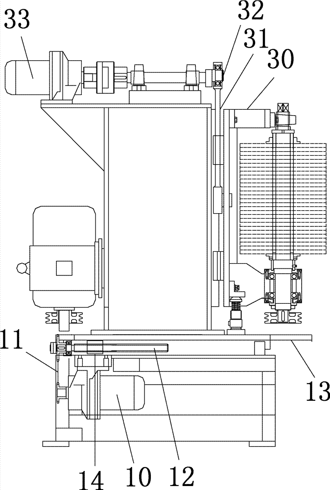
Concrete, described polishing wheel is the cloth wheel, and the cloth wheel connects crane, and crane connects elevating lever, and elevating lever connects eccentric shaft, and eccentric shaft connects lifting motor.Lifting motor makes cloth wheel in up and down lifting of rotary course by eccentric shaft, on the one hand, can eliminate the sand road vestige of the sand paper machine grinding of preceding working procedure, on the other hand, stays the polishing vestige in the time of can avoiding in this technique buffing.
The finishing method of above-mentioned polisher for side positions of painted piece of piano is characterized in that: may further comprise the steps:
1., the piano paint component is placed on the traversing workbench, the first casting die cylinder-pressing piano paint component at the top of traversing workbench is opened the polissoir power supply, and each self-driven polishing wheel of motor rotates, and each self-driven polishing wheel of lifting motor moves up and down;
2., the first drive motors drives the rotation of the first chain, the first rod member and clutch shaft bearing also rotate, driving traversing workbench comes and goes traversing, in coming and going traversing process, polishing wheel polishes the horizontal edge of piano paint component, and current sensor sends to horizontal edge PLC to the actual current value of motor in the polishing process;
3., horizontal edge PLC compares actual current value and setting current value range, when actual current value less than setting current value range, the distance that polishing wheel and horizontal edge are described is too large, polishing force is too little, then control the feeding electric motor starting, by screw mandrel upper dovetail is moved and drive polishing wheel and the close horizontal edge of motor; When actual current value greater than setting current value range, the distance that polishing wheel and horizontal edge are described is too little, and polishing force is too large, then controls the feeding electric motor starting, upper dovetail is moved drive polishing wheel and motor away from horizontal edge by screw mandrel, set in the current value range until actual current value is in;
4., horizontal edge polishing finishes, the first casting die cylinder at the top of traversing workbench unclamps, and manually the piano paint component is shifted onto transition frame, shifts the translation workbench onto again, the second casting die cylinder-pressing piano paint component at the top of translation workbench;
5., the second drive motors drives the rotation of the second chain, the second rod member and the second bearing also rotate, drive the translation workbench and come and go translation, in the process that comes and goes translation, polishing wheel polishes the straight flange of piano paint component, and current sensor sends to straight flange PLC to the actual current value of motor in the polishing process;
6., straight flange PLC compares actual current value and setting current value range, when actual current value less than setting current value range, the distance that polishing wheel and straight flange are described is too large, polishing force is too little, then control the feeding electric motor starting, by screw mandrel upper dovetail is moved and drive polishing wheel and the close straight flange of motor; When actual current value greater than setting current value range, the distance that polishing wheel and straight flange are described is too little, and polishing force is too large, then controls the feeding electric motor starting, upper dovetail is moved drive polishing wheel and motor away from straight flange by screw mandrel, set in the current value range until actual current value is in;
7., straight flange polishing finishes, the second casting die cylinder at the top of translation workbench unclamps, and manually the piano paint component is shifted onto hydraulic elevating platform.
The present invention has advantages of as follows with respect to prior art:
This polisher for side positions of painted piece of piano once can be finished the processing that gross thickness is many paint components of 400mm to the polishing of four peripheries of the square paint plate of piano, and workpiece is linked to be a production line from blowing, horizontal edge polishing, straight flange polishing.The Traditional Man polishing time is about 25-35 minutes, and be 8 minutes the process time of polissoir of the present invention, attached helping 2 minutes time, overall process 10 minutes, improved production efficiency, alleviated workman's labour intensity, the workman easily grasps, qualification to the workman is less demanding, and the product polishing quality is got a promotion.
The polish pressure control of the machine is to realize automatically control, and its principle mainly is:
The surface finish of piano paint component is except outside the Pass having with the kind of the linear velocity of polishing wheel and cloth, grinding agent and granularity, must the control polishing wheel in process to the polish pressure on paint component surface, when polish pressure was not enough, production efficiency was excessively low; When polish pressure is excessive, can produce the overheated paint films that damages because friction makes the surface.How controlling polish pressure becomes the key of mechanization polishing.If the position of polishing wheel is not adjustment, when the kind of paint component, size change over, the workman can only adjust the position of polishing wheel by rule of thumb so, and polish pressure just is difficult to unanimously, and crudy is difficult to constant.
Polish pressure * coefficient of friction=paint component is to the frictional force of polishing wheel, and paint component is to the frictional force of the polishing wheel resistance that is subject to of polishing wheel namely, and this resistance can be embodied on the current value of motor, and the large current value of resistance is large, and the little current value of resistance is little.So can get detection means: detect polish pressure, can detect the current value of motor, regulating measure: be the distance of control polishing wheel and paint component, when distance is little, polish pressure is just large, when distance greatly, polish pressure is just little.Current sensor sends to straight flange PLC or horizontal edge PLC to the actual current value of motor in the polishing process, PLC control feeding motor forward or counter-rotating, polishing wheel advances or retreats, distance with control polishing wheel and paint component, make polish pressure moderate, the constant product quality of processing, surface aesthetic.
Description of drawings
Fig. 1 is the top view of horizontal edge polishing machine of the present invention and transition frame.
Fig. 2 is the front view of horizontal edge polishing machine.
Fig. 3 is the enlarged drawing on Fig. 2 left side.
Fig. 4 is the upward view of traversing workbench.
Fig. 5 is the top view of straight flange polishing machine.
Fig. 6 is the front view of straight flange polishing machine.
Fig. 7 is the top view of hydraulic elevating platform.
Fig. 8 is the front view of hydraulic elevating platform.
Fig. 9 is the circuit controling drawing of horizontal edge PLC.
Figure 10 is the circuit controling drawing of straight flange PLC.
Number in the figure and title correspondence are as follows:
| 1 |
The piano paint component |
2 |
Straight flange |
| 3 |
Horizontal edge |
4 |
The horizontal edge polishing machine |
| 5 |
Transition frame |
6 |
The straight flange polishing machine |
| 7 |
Hydraulic elevating platform |
8 |
Polishing wheel |
| 9 |
Motor |
10 |
The feeding motor |
| 11 |
Chain sprocket |
12 |
Screw mandrel |
| 13 |
Upper dovetail |
14 |
The feed screw nut |
| 15 |
Traversing workbench |
16 |
The first casting die cylinder |
| 17 |
The translation workbench |
18 |
The first driver slot |
| 19 |
The first drive motors |
20 |
The first sprocket wheel |
| 21 |
The first chain |
22 |
The second sprocket wheel |
| 23 |
The first rod member |
24 |
Clutch shaft bearing |
| 25 |
The second drive motors |
26 |
The 3rd sprocket wheel |
| 27 |
The second chain |
28 |
The 4th sprocket wheel |
| 29 |
The second rod member |
30 |
Crane |
| 31 |
Elevating lever |
32 |
Eccentric shaft |
| 33 |
Lifting motor |
34 |
The second casting die cylinder |
The specific embodiment
The invention will be further described below in conjunction with drawings and Examples.
Polisher for side positions of painted piece of piano shown in Fig. 1 ~ 8, the position, limit of the direction of advance of piano paint component is straight flange, the limit position vertical with straight flange is horizontal edge on the horizontal plane; Polissoir comprises horizontal edge polishing machine, transition frame, straight flange polishing machine and the hydraulic elevating platform that is arranged in order;
The horizontal edge polishing machine respectively is provided with 1 polishing wheel at two horizontal edges of piano paint component, the straight flange polishing machine respectively is provided with 2 polishing wheels at two straight flanges of piano paint component, each polishing wheel connects separately driving by a motor, each motor is installed current sensor, all current sensors of horizontal edge all are connected to horizontal edge PLC, and all current sensors of straight flange all are connected to straight flange PLC;
6 polishing wheels and connected 6 motors are arranged on 6 feed microadjusting mechanisms.
In order to adjust the distance on polishing wheel and piano paint component surface, each feed microadjusting mechanism includes feeding motor, chain sprocket, screw mandrel and upper dovetail, the feeding motor connects horizontal edge PLC or straight flange PLC, the feeding motor connects the driving screw mandrel by chain sprocket, feed screw nut below the upper dovetail is enclosed within the screw mandrel outside, and polishing wheel and connected motor are arranged on the dovetail.
In order to realize the location to the piano paint component, the horizontal edge polishing machine comprises traversing workbench, and traversing workbench bottom is provided with guide wheel and guide rail, and the top of traversing workbench is provided with the first casting die cylinder, 19 piano paint components are placed on the traversing workbench, and the first casting die cylinder is being pressed 19 piano paint components.
In order to realize the location to the piano paint component, the straight flange polishing machine comprises the translation workbench, and translation workbench bottom is provided with guide wheel and guide rail, and the top of translation workbench is provided with the second casting die cylinder, 19 piano paint components are placed on the translation workbench, and the second casting die cylinder is being pressed 19 piano paint components.
Promote the piano paint component for the ease of the workman, the top of traversing workbench, transition frame, translation workbench and hydraulic elevating platform all is the cylinder that is arranged in parallel.
In order to realize the transverse shifting of traversing workbench, traversing workbench bottom is provided with first driver slot vertical with cylinder, be provided with the first drive motors below the traversing workbench, the first drive motors connects the first sprocket wheel, the first sprocket wheel connects the second sprocket wheel by the first chain, and the first chain is provided with the first rod member, and the first rod member top is provided with clutch shaft bearing, clutch shaft bearing places in the first driver slot, and the first chain is parallel with cylinder.
For realize the translation workbench directly to movement, translation workbench bottom is provided with second driver slot parallel with cylinder, be provided with the second drive motors below the translation workbench, the second drive motors connects the 3rd sprocket wheel, the 3rd sprocket wheel connects the 4th sprocket wheel by the second chain, and the second chain is provided with the second rod member, and the second rod member top is provided with the second bearing, the second bearing places in the second driver slot, and the second chain is vertical with cylinder.
Polishing wheel is the cloth wheel, and the cloth wheel connects crane, and crane connects elevating lever, and elevating lever connects eccentric shaft, and eccentric shaft connects lifting motor.Lifting motor makes cloth wheel in up and down lifting of rotary course by eccentric shaft, on the one hand, can eliminate the sand road vestige of the sand paper machine grinding of preceding working procedure, on the other hand, stays the polishing vestige in the time of can avoiding in this technique buffing.
Fig. 9 is the circuit controling drawing of horizontal edge PLC.Figure 10 is the circuit controling drawing of straight flange PLC.
The finishing method of above-mentioned polisher for side positions of painted piece of piano may further comprise the steps:
1., 19 piano paint components are stacked neatly be placed on the traversing workbench, 2 first casting die cylinder-pressing piano paint components at the top of traversing workbench, open the polissoir power supply, 6 each self-driven polishing wheels of motor rotate, and 6 each self-driven polishing wheels of lifting motor move up and down;
2., the first drive motors drives the rotation of the first chain, the first rod member and clutch shaft bearing also rotate, driving traversing workbench comes and goes traversing, in coming and going traversing process, 2 polishing wheels polish the horizontal edge of piano paint component, and current sensor sends to horizontal edge PLC to the actual current value of motor in the polishing process;
3., horizontal edge PLC compares actual current value and setting current value range, when actual current value less than setting current value range, the distance that polishing wheel and horizontal edge are described is too large, polishing force is too little, then control the feeding electric motor starting, by screw mandrel upper dovetail is moved and drive polishing wheel and the close horizontal edge of motor; When actual current value greater than setting current value range, the distance that polishing wheel and horizontal edge are described is too little, and polishing force is too large, then controls the feeding electric motor starting, upper dovetail is moved drive polishing wheel and motor away from horizontal edge by screw mandrel, set in the current value range until actual current value is in;
4., horizontal edge polishing finishes, the first casting die cylinder at the top of traversing workbench unclamps, and manually the piano paint component is shifted onto transition frame, shifts the translation workbench onto again, 2 second casting die cylinder-pressing piano paint components at the top of translation workbench;
5., the second drive motors drives the rotation of the second chain, the second rod member and the second bearing also rotate, drive the translation workbench and come and go translation, in the process that comes and goes translation, 4 polishing wheels polish the straight flange of piano paint component, and current sensor sends to straight flange PLC to the actual current value of motor in the polishing process;
6., straight flange PLC compares actual current value and setting current value range, when actual current value less than setting current value range, the distance that polishing wheel and straight flange are described is too large, polishing force is too little, then control the feeding electric motor starting, by screw mandrel upper dovetail is moved and drive polishing wheel and the close straight flange of motor; When actual current value greater than setting current value range, the distance that polishing wheel and straight flange are described is too little, and polishing force is too large, then controls the feeding electric motor starting, upper dovetail is moved drive polishing wheel and motor away from straight flange by screw mandrel, set in the current value range until actual current value is in;
7., straight flange polishing finishes, 2 second casting die cylinders at the top of translation workbench unclamp, and manually the piano paint component are shifted onto hydraulic elevating platform, so far glossing finishes.
The above-mentioned specific embodiment is the preferred embodiments of the present invention, can not limit the present invention, and other any change or other equivalent substitute mode that does not deviate from technical scheme of the present invention and make is included within protection scope of the present invention.