CN102231315B - Heat exchange device for blast-proof shell of mine explosion-proof dry-type transformer - Google Patents
Heat exchange device for blast-proof shell of mine explosion-proof dry-type transformer Download PDFInfo
- Publication number
- CN102231315B CN102231315B CN 201110100563 CN201110100563A CN102231315B CN 102231315 B CN102231315 B CN 102231315B CN 201110100563 CN201110100563 CN 201110100563 CN 201110100563 A CN201110100563 A CN 201110100563A CN 102231315 B CN102231315 B CN 102231315B
- Authority
- CN
- China
- Prior art keywords
- copper water
- water heat
- heat
- heat pipe
- proof
- Prior art date
- Legal status (The legal status is an assumption and is not a legal conclusion. Google has not performed a legal analysis and makes no representation as to the accuracy of the status listed.)
- Expired - Fee Related
Links
Images

Landscapes
- Transformer Cooling (AREA)
- Heat-Exchange Devices With Radiators And Conduit Assemblies (AREA)
Abstract
The invention discloses a heat exchange device for a blast-proof shell of a mine explosion-proof air-immersed transformer. The heat exchange device is characterized in that a wick and a heat-conductive liquid are arranged in a copper water heat tube; the copper water heat tube is embedded in an inner wall straight groove between the upper and lower semi-shells of a ripple shell accommodating a transformer; the copper water heat tube is formed by connecting copper tubes which are continuous and vertical to the central shaft of the ripple shell; the inside of the copper water heat tube is vacuumed to a negative pressure of 1.3*10<-1>-1.3*10<-4> Pa and is filled with the heat-conductive liquid; the wick is made of capillary porous materials; one section of the copper water heat tube, positioned at the upper-half part of the ripple shell is an evaporation end; and one section of the copper water heat tube, positioned at the lower-half part of the ripple shell is a condensation end. According the invention, the copper water heat tube is used, so that the heat dissipation effect of the mine explosion-proof air-immersed transformer is more obvious; a single heat dissipation mode that the heat dissipation problem is solved only depending on a high air volume motor is broken away, so that even though a low-revolving-speed low-air-volume motor is adopted, a radiator still can achieve a satisfied effect, and simultaneously, the noise problem which puzzles air cooling heat dissipation is well solved.
Description
Technical field
The present invention relates to a kind of heat-exchange device, particularly for the heat-exchange device of the explosion-proof casing of mine explosion isolated dry-type transformer.
Background technology
In the coal production of down-hole, flameproof dry-type transformer is installed in the airtight housing, the heat that transformer produces when work is to rely on the conduction of housing to be dispersed in the air, and the heat major part that enclosure interior institute installing component produces is by the cross-ventilation of enclosure interior and is radiated on the housing, carries out heat exchange by housing and extraneous air again and dispels the heat.
The heat that no-load loss when no-load transformer moves produces is to pass to housing and close low-voltage coil unshakable in one's determination by the cross-ventilation in the housing, and the heat that produces below the middle part unshakable in one's determination can't distribute by the housing of bottom, but born heat radiation by upper body, this situation very easily causes condensation to occur, and jeopardizes the mine production safety.When transformer moved under nominal load, coil and iron core generated heat simultaneously, because load loss generally is 1.8-2.2 times of no-load loss, caused the coil local temperature too high.
Traditional down-hole heat abstractor generally is to adopt large fan to dispel the heat or adopt conventional heat pipe to be dispelled the heat in dry-type transformer inside, large fan not only noise is huge, and itself be a power consumption equipment, in case breaking down, it will affect the safe operation of whole mine movable load center.Traditional heat pipe only dispels the heat to transformer, can not solve the heat dissipation problem of the explosion-proof casing of transformer.And when the explosion-proof casing of transformer in the situation that humidity because the bulk temperature inequality when the condensation phenomenon occurring, not only can cause the accident of human electric shock to occur, also can cause the large tracts of land paralysis of whole underground power supply system.Be difficult to satisfy safety requirements so in the coal production of down-hole, only rely on traditional heat abstractor to dispel the heat.
Summary of the invention
The objective of the invention is to produce condensation problem owing to heat radiation is uneven for the explosion-proof casing that solves mine explosion-proof dry-type transformer in the prior art, propose a kind of annular copper Water Heat Pipes that utilizes the dry-type transformer explosion-proof casing is carried out the heat transmission, closely so that heat evenly distributes, reach the heat-exchange device of anti-dewing purpose.
The technical solution that the present invention adopts is: have liquid-sucking core and heat-conducting liquid, liquid-sucking core and heat-conducting liquid all are arranged in the copper water heat pipe, copper water heat pipe is embedded in the inwall straight trough of upper and lower two halves housing of the corrugated shell that holds transformer, copper water heat pipe is connected to form by the continuous copper pipe perpendicular to the corrugated casing central shaft, and the inside of copper water heat pipe is pumped into 1.3 * 10
-1~1.3 * 10
-4The negative pressure of Pa is filled with heat-conducting liquid, and liquid-sucking core is made by the capillary porous material; The copper water heat pipe that is positioned at one section of the corrugated casing first half is that the copper water heat pipe of one section of evaporation ends, bottom is condensation end.
The present invention's advantage compared with prior art is:
1, the present invention uses copper water heat pipe so that the radiating effect of mine explosion isolated dry-type transformer is more obvious, broken away from the single radiating mode that the high air quantity motor of simple dependence solves heat dissipation problem, even if adopt copper water heat pipe so that radiator adopts the slow-speed of revolution, low air quantity motor, can obtain promising result equally, simultaneously so that the noise problem of puzzlement wind-cooling heat dissipating well improved.
2, extended surface can be adopted easily in the outside of copper water heat pipe, and making conducts heat significantly strengthens, and the ratio of heat transfer coefficient conventional heat pipe exceeds 5-10 doubly.Copper water heat pipe can be realized pure countercurrent flow, thereby has larger heat transfer temperature difference.In the situation that transmit identical heat, the copper water heat pipe heat exchanger needs less heat transfer area, thereby compact conformation, and floor space and metal wastage greatly reduce.The heat transfer area of copper water heat pipe and heat pipe radical easily increase and decrease, thereby have larger retractility.The heat exchange of cold and hot two fluids all is the inside heat pipe heat exchange, and lip-deep dust stratification ratio is easier to clean, therefore easy to maintenance.The element of copper water heat pipe has good removable transsexual, is convenient to safeguard and maintenance.Because heat-pipe elements is independently each other, be arranged together in sequence.Unlike traditional tubular heat exchanger, between the pipe and bobbin carriage be to be linked togather mutually to consist of an integral body, thereby be not easy to dismounting.Some heat exchange of heat pipe even under working condition need not be shut down replacing and the maintenance that just can carry out heat-pipe elements.The area of copper water heat pipe bringing-up section and cooling section can carry out flexible design according to the equipment needs, and tube wall temperature also just can be adjusted accordingly, thereby have the ability of stronger dew-point corrosion resistant.In addition, even one or the corrosion of several heat pipes have been leaked, also can not cause the blending of cold and hot two kinds of fluids.
Description of drawings
Below the present invention is further elaborated by the drawings and specific embodiments;
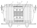
Fig. 1 is that the master of structure of the present invention looks cross-sectional schematic;
Fig. 2 is the A-A cutaway view of Fig. 1;
Among the figure: 1. corrugated casing; 2. copper water heat pipe; 3. liquid-sucking core; 4. heat-conducting liquid; 5. transformer.
Embodiment
Referring to Fig. 1-2, transformer 5 is installed in the corrugated casing 1 that holds its structure, corrugated casing 1 is that upper and lower two halves housing connection forms, the cross section of corrugated casing 1 is annular, the longitudinal section is the vertical moire shape, be that the longitudinal section is the continuous corrugated perpendicular to the arrangement of corrugated casing 1 central shaft, therefore, corrugated casing 1 inwall is comprised of several straight troughs perpendicular to corrugated casing 1 central shaft.The present invention has liquid-sucking core 3, heat-conducting liquid 4 and copper water heat pipe 2, copper water heat pipe 2 and is embedded in the inwall straight trough of upper and lower two halves housing of corrugated shell 1, the structure of copper water heat pipe 2 and corrugated casing 1 match, and are to be connected to form by the continuous copper pipe perpendicular to corrugated casing 1 central shaft.Liquid-sucking core 3 and heat-conducting liquid 4 are set in copper water heat pipe 2.The inside of copper water heat pipe 2 is pumped into 1.3 * 10
-1~1.3 * 10
-4The negative pressure of Pa is filled with heat-conducting liquid 4, heat-conducting liquid 4 be boiling point low, hold volatile liquid, liquid-sucking core 3 is to be made by the capillary porous material.
The copper water heat pipe 2 that is installed in one section of corrugated casing 1 first half is evaporation ends, and the copper water heat pipe 2 that is installed in one section of corrugated casing 1 bottom is condensation end.When the heat major part is gathered in corrugated casing 1 first half in the transformer running, be that the evaporation ends of copper water heat pipe 2 is when being heated, heat-conducting liquid 4 evaporates rapidly, steam flows to corrugated casing 1 Lower Half under small pressure differential, it is the condensation end of copper water heat pipe 2, and releases heat, regelation becomes heat-conducting liquid 4, heat-conducting liquid 4 flows back to evaporation section along liquid-sucking core 3 by the effect of capillary force again, so circulation is more than, and heat is by liquid-sucking core 3, heat-conducting liquid 4 and copper water heat pipe 2 are passed to corrugated casing 1 Lower Half, reach an other end by an end of copper water heat pipe 2, realize the heat exchange of corrugated casing 1, fundamentally solve condensation problem.
Claims (1)
1. explosion-proof shell heat exchanger for mine explosion-proof dry type transformer, have liquid-sucking core (3) and heat-conducting liquid (4), it is characterized in that: liquid-sucking core (3) and heat-conducting liquid (4) all are arranged in the copper water heat pipe (2), on the corrugated casing (1) that holds transformer is, lower two halves housing connection forms, the cross section of corrugated casing (1) is annular, the longitudinal section is the continuous corrugated perpendicular to the arrangement of corrugated casing (1) central shaft, the inwall of corrugated casing (1) is comprised of several straight troughs perpendicular to corrugated casing (1) central shaft, and described copper water heat pipe (2) is embedded in the upper of corrugated casing (1), in the inwall straight trough of lower two halves housing; The structure of copper water heat pipe (2) and corrugated casing (1) match, and copper water heat pipe (2) is connected to form by continuous copper pipe, and this continuous copper pipe is perpendicular to corrugated casing (1) central shaft; The inside of copper water heat pipe (2) is pumped into 1.3 * 10
-1~1.3 * 10
-4The negative pressure of Pa is filled with heat-conducting liquid (4); Liquid-sucking core (3) is made by the capillary porous material; The copper water heat pipe (2) that is positioned at one section of the upper half-shell of corrugated casing (1) is condensation end for evaporation ends, the copper water heat pipe (2) that is positioned at one section of the housing lower half of corrugated casing (1).
Priority Applications (1)
| Application Number | Priority Date | Filing Date | Title |
|---|---|---|---|
| CN 201110100563 CN102231315B (en) | 2011-04-21 | 2011-04-21 | Heat exchange device for blast-proof shell of mine explosion-proof dry-type transformer |
Applications Claiming Priority (1)
| Application Number | Priority Date | Filing Date | Title |
|---|---|---|---|
| CN 201110100563 CN102231315B (en) | 2011-04-21 | 2011-04-21 | Heat exchange device for blast-proof shell of mine explosion-proof dry-type transformer |
Publications (2)
| Publication Number | Publication Date |
|---|---|
| CN102231315A CN102231315A (en) | 2011-11-02 |
| CN102231315B true CN102231315B (en) | 2013-01-23 |
Family
ID=44843872
Family Applications (1)
| Application Number | Title | Priority Date | Filing Date |
|---|---|---|---|
| CN 201110100563 Expired - Fee Related CN102231315B (en) | 2011-04-21 | 2011-04-21 | Heat exchange device for blast-proof shell of mine explosion-proof dry-type transformer |
Country Status (1)
| Country | Link |
|---|---|
| CN (1) | CN102231315B (en) |
Families Citing this family (4)
| Publication number | Priority date | Publication date | Assignee | Title |
|---|---|---|---|---|
| CN102360859A (en) * | 2011-11-16 | 2012-02-22 | 江苏正佰电气有限公司 | Conveniently radiating three-phase transformer |
| CN108766736A (en) * | 2018-04-24 | 2018-11-06 | 浙江派尔电气有限公司 | A kind of transformer heat-dissipating casing |
| CN109831840B (en) * | 2019-01-17 | 2021-07-16 | 佛山宁宇科技股份有限公司 | Water heating pipe using chromium fiber as heating body |
| CN113517113B (en) * | 2021-09-13 | 2021-11-16 | 江苏亨特集团华特电气有限公司 | Water flow curtain wall type dustproof cooling transformer |
Family Cites Families (6)
| Publication number | Priority date | Publication date | Assignee | Title |
|---|---|---|---|---|
| DE2739631C3 (en) * | 1977-09-02 | 1981-01-08 | Siemens Ag, 1000 Berlin Und 8000 Muenchen | Flameproof, flameproof dry-type transformer |
| FR2513803B1 (en) * | 1981-09-28 | 1988-07-29 | Alsacienne Installation Tech | TRANSFORMER, PARTICULARLY OF THE EXPLOSION-PROOF TYPE |
| JPS631012A (en) * | 1986-06-20 | 1988-01-06 | Tokyo Electric Power Co Inc:The | Directly buried type transformer |
| JP2002353035A (en) * | 2001-05-23 | 2002-12-06 | Nissin Electric Co Ltd | Electric apparatus |
| CN201638640U (en) * | 2010-04-23 | 2010-11-17 | 上官远定 | Shell-type transformer dissipating heat by means of evaporative cooling |
| CN202084388U (en) * | 2011-04-21 | 2011-12-21 | 江苏大学 | Explosion-proof shell heat exchanger for mine explosion-proof dry type transformer |
-
2011
- 2011-04-21 CN CN 201110100563 patent/CN102231315B/en not_active Expired - Fee Related
Non-Patent Citations (3)
| Title |
|---|
| JP昭63-1012A 1988.01.06 |
| 万黎等.变压器热管散热技术.《湖北电力》.2010,第34卷(第增I期),99-101. * |
| 雷东强等.热管技术在变压器中的应用研究.《变压器》.2007,第44卷(第1期),37-40. * |
Also Published As
| Publication number | Publication date |
|---|---|
| CN102231315A (en) | 2011-11-02 |
Similar Documents
| Publication | Publication Date | Title |
|---|---|---|
| CN200941023Y (en) | Loop parallel heat pipe and heat exchanger thereof | |
| CN103363571B (en) | Superconductive heat pipe electric heater | |
| CN109990262B (en) | Auxiliary heating steam generator | |
| CN102231315B (en) | Heat exchange device for blast-proof shell of mine explosion-proof dry-type transformer | |
| CN104197612B (en) | A kind of high efficiency and heat radiation assembly of semiconductor freezer | |
| CN106895727B (en) | Finned tube heat exchanger, application thereof and waste heat boiler | |
| CN105656352A (en) | Underground heat power generation device | |
| CN104807350A (en) | Heat exchanger of air conditioner | |
| CN102980429A (en) | Loop thermosyphon heat dissipation device | |
| CN205481748U (en) | Electromagnetism energy storage heat source device | |
| CN2916429Y (en) | Thermal-superconductive electric heating device | |
| CN202229285U (en) | Fireless multifunctional heating drier | |
| CN202084388U (en) | Explosion-proof shell heat exchanger for mine explosion-proof dry type transformer | |
| CN202549556U (en) | Transformer heat pipe radiating device | |
| CN109631635B (en) | Loop heat pipe heat accumulator with variable heat accumulation capacity | |
| CN206602010U (en) | A kind of radiating device for dry-type transformer | |
| CN201916992U (en) | Water-free fin radiator | |
| CN205882492U (en) | Box type transformer station | |
| CN214043349U (en) | Heat extraction and dissipation device of oil-immersed power transformer | |
| CN109945705B (en) | Loop heat pipe heat accumulator with highly-variable heat release capacity | |
| CN202734609U (en) | Expansion pipe type copper radiator | |
| CN201413068Y (en) | Vacuum phase-change heat radiator | |
| CN207407522U (en) | A kind of high-efficiency energy-saved electric-heating boiler | |
| CN206073242U (en) | A kind of central heating system heat-pipe type radiator | |
| CN219061742U (en) | Thermoelectric integrated partition type mine air cooler |
Legal Events
| Date | Code | Title | Description |
|---|---|---|---|
| C06 | Publication | ||
| PB01 | Publication | ||
| C10 | Entry into substantive examination | ||
| SE01 | Entry into force of request for substantive examination | ||
| C14 | Grant of patent or utility model | ||
| GR01 | Patent grant | ||
| CF01 | Termination of patent right due to non-payment of annual fee |
Granted publication date: 20130123 Termination date: 20150421 |
|
| EXPY | Termination of patent right or utility model |