CN102183251A - Electromagnetic tracking method based on inductance coil - Google Patents
Electromagnetic tracking method based on inductance coil Download PDFInfo
- Publication number
- CN102183251A CN102183251A CN2011100609834A CN201110060983A CN102183251A CN 102183251 A CN102183251 A CN 102183251A CN 2011100609834 A CN2011100609834 A CN 2011100609834A CN 201110060983 A CN201110060983 A CN 201110060983A CN 102183251 A CN102183251 A CN 102183251A
- Authority
- CN
- China
- Prior art keywords
- coil
- telefault
- sensor
- electromotive force
- lead
- Prior art date
- Legal status (The legal status is an assumption and is not a legal conclusion. Google has not performed a legal analysis and makes no representation as to the accuracy of the status listed.)
- Granted
Links
Images


Landscapes
- Measurement Of Length, Angles, Or The Like Using Electric Or Magnetic Means (AREA)
- Geophysics And Detection Of Objects (AREA)
Abstract
The invention relates to an electromagnetic tracking method based on an inductance coil. The inductance coil detects the magnitude of a magnetic field around a current carrying wire, so as to determine a position relationship between a moving object and the current carrying wire. Through the research on the number and the arrangement of the inductance coils, an electromagnetic-guidance-based tacking method consisting of seven inductance sensors is designed, so the detection of a magnetic signal under different wire arrangements and complicated magnetic field environment is well realized so as to determine the position. A detection result is more stable, reliable and effective, and the device has the characteristics of simpleness, reliability and wide application fields.
Description
Technical field
The present invention relates to a kind of sensor technology, particularly a kind of electromagnetism tracking method based on telefault.
Background technology
Automatic guided vehicle (AGV) had obtained development at full speed as a kind of mobile robot in recent years, was mainly used in flexible manufacturing system (FMS), flexible assembly system (with AGV as movable mounting plate), automatic stereowarehouse and some other industry as haulage equipment.The widespread usage of its sensor technology in automatic guided vehicle.AGV mainly is made of oriented module, walking module, orientation sensor, microprocessor, communication device, shifting apparatus and accumulator etc.Wherein, the orientation sensor module is one of key modules of AGV, and AGV experiences surroundings by orientation sensor, and walks along correct path with certain precision by control device assurance AGV dolly.At present, sensing mode relatively more commonly used has modes such as laser, ccd image processing and electromagnetism.
Because under laser and the condition of CCD as sensor, control strategy and algorithm be more complicated all, and is subjected to the influence of extraneous light bigger.Therefore, adopt telefault to become the new trend of tracking pilotage as sensor.
Summary of the invention
The present invention be directed to present mobile apparatus philtrum sensor control complexity and be subjected to extraneous light to influence big problem, a kind of electromagnetism tracking method based on telefault has been proposed, with a kind of electromagnetism tracking scheme of telefault as sensor, by research, thereby determine position relation between moving object and current carrying conductor to the quantity and the layout of telefault.
Technical scheme of the present invention is: a kind of electromagnetism tracking method based on telefault, comprise 7 sensor and microprocessors of forming by telefault, and the method concrete steps are as follows:
1) set up rectangular coordinate system in space, in the testee coordinate system, the direction that the definition object advances is the Y-axis forward, lead is put in the shop by path central authorities, galvanization in the lead, and size of current and frequency are known, right-hand side along Y-axis is the forward of X-axis, directly over the Z axle directed towards object; Horizontal coil refers to the telefault of hub of a spool parallel axes in the Z axle, and vertical coil refers to the coil of hub of a spool parallel axes in X-axis, and then induction electromotive force can be approximately in the coil:
Be the rate of change that the size of induction electromotive force is proportional to electric current in the coil, be inversely proportional to hub of a spool to lead apart from r, K is a slope;
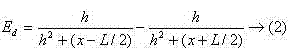
2) loop A and the B of two levels are installed in testee the place ahead, the angle that two loop A and B set toward rear-inclined, set angle is 15 degree: these two coils be spaced apart L, the height of coil is h, the coordinate of left side loop A is (x+L/2, h, z), position (x-L/2, the h of the right coil B, z), the difference of the induction electromotive force of two telefaults
 , electromotive force difference Ed and displacement x are monotonic quantitys;
3) telefault of middle: on the layout of two horizontal coil A and B, increased a telefault C who is positioned at the middle, telefault C with about two sensors A and B level at a distance of be L/2 all, the location variable usefulness of testee and lead
PosRepresentative, then its expression formula is derived as follows:
Wherein intermediate coil C influence value is
Ad_m,
 Be sensor
ADetect the electromotive force size,
Be sensor
ADetect the electromotive force size,
 Be sensor
BDetected electromotive force size,
KSlope for potential difference values Ed straight line;
Be sensor
BDetected electromotive force size,
KSlope for potential difference values Ed straight line;
4) at the loop A and the B sustained height of two levels, be parallel to the y direction of principal axis about two coil D and the Es identical with intermediate distance are installed, the angle that two coil D and E set to intermediate, inclined, angle is 15 degree;
5) two horizontal coil F and G are placed in adjacent two horizon sensor A and B back, spacing and highly with sensor A and B;
6) 7 telefault sensor signals are sent in the microprocessor handle after, obtain the locus of path lead.
What described microprocessor adopted is that model is the Freescale chip of MC9S12XS128.
Beneficial effect of the present invention is: the present invention is based on the electromagnetism tracking method of telefault, can well solve under different conductor layout and complicated magnetic field environment, to the detection of magnetic signal, thereby determine the position, testing result is more stable, reliable, effective.Device has simply, reliable, application is characteristics widely.
Description of drawings
Fig. 1 is the induction field schematic diagram around the lead;
Fig. 2 is bodywork reference frame figure;
Fig. 3 is that two horizontal coils detect synoptic diagram;
Fig. 4 is the matched curve figure that two horizontal coils detect Ed;
Fig. 5 is that 3 coils detect synoptic diagram;
Fig. 6 is the graph of a relation that 3 coil detecting sensor C detect electric field intensity and runway center line marking position;
Fig. 7 is that 3 coils detect the matched curve of using in the control;
Fig. 8 is that 5 coils detect synoptic diagram;
Fig. 9 is that 7 coils detect synoptic diagram.
Embodiment
According to Maxwell's Theory of Electromagnetic Field, exchange current can produce the electromagnetic field of alternation around lead.Can the derive locus of measurement point distance of wire of intensity by detecting corresponding electromagnetic field and direction.Place telefault in alternating magnetic fields, electromagnetic induction can make the electric current that produces alternation in the coil, as shown in Figure 1.Under the set condition of electric current, induction current in the coil (perhaps voltage) is the function of locus in lead location and lead.
The track of moving object mainly divides straight way, big curved, little curved and intersect several types such as bend.Aftermentioned explanation for convenience is an example with dolly 4, sets up rectangular coordinate system in space as shown in Figure 2.In the dolly bodywork reference frame, definition dolly 4 direction of advancing is the Y-axis forward, is the forward of X-axis along the right-hand side of Y-axis, and the Z axle points to directly over the dolly 4.Horizontal coil 1 is meant the telefault of hub of a spool parallel axes in the Z axle, vertical coil 2 is meant the coil of hub of a spool parallel axes in X-axis, by analyzing as can be known, central axis is parallel to electromotive force that the coil of Y-axis senses much smaller than horizontal coil and vertical coil.
The power frequency that passes through in the lead 3 is 20kHz, and coil is less, makes that hub of a spool is r to the distance of lead, thinks around the lead that among a small circle it is that then induction electromotive force can be approximately in the coil uniformly that internal magnetic field distributes:
Be the rate of change that the size of induction electromotive force is proportional to electric current in the coil, be inversely proportional to hub of a spool to lead apart from r.Wherein constant K is and coil layout, a current changing rate amount relevant with some physics constants, and concrete induction electromotive force constant must practical measurement be determined.
Because telefault can be used for responsive magnetic field, can draw the distance of dolly and track center line according to the relation of above-mentioned detected induction electromotive force and distance.But the quantity of telefault and layout influence the reception and the position of signal to be found the solution, and therefore, the design's emphasis is exactly the analysis to inductance quantity and layout, designs a kind of rational detection scheme.
Sensor placement: if only use a telefault as sensor, induction electromotive force E is the even function of position x, is merely able to be reflected to the size of the absolute value x of horizontal level, about can't differentiating.Therefore, must use two or more coil to detect as sensor.
Two horizontal coils detect: uses at a distance of two inductive coil A and the B of length as L, the difference Ed of two coil-induced electromotive force of calculating.The whole model of telefault installation and dolly as shown in Figure 3.Suppose to install the coil of two levels in car mould the place ahead.These two coils be spaced apart L, the height of coil is h.The coordinate of left side coil be (x+L/2, h, z), the position of the coil on the right (x-L/2, h, z).Because Distribution of Magnetic Field is to be the concentric circles at center with the Y-axis, thus in calculating magnetic field intensity, only consider coordinate (x, Z).Because the axis of coil is a level, so induction electromotive force has reflected the horizontal component in magnetic field.According to formula (1) can know induction electromotive force size with
 Be directly proportional.
Suppose h=6cm, require dolly in the 15cm scope of the distance runway centerline left and right sides, to move, i.e. x ∈ (15 ,+15) cm, two sensor horizontal ranges are 20cm, calculate the difference of the induction electromotive force of two telefaults
 The matched curve figure of the Ed that works it out with MATLAB as shown in Figure 4, this curve is represented the variation tendency of Ed.
As seen, in the time of directly over dolly is positioned at lead, the both sides electric potential difference is zero; When the left side of dolly coil or the right coil are positioned at directly over the lead, the difference maximum on both sides, and between (10,10) cm, it is linear that difference is, and promptly electromotive force difference Ed and displacement x are monotonic quantitys.Therefore can use this amount to turn to and carry out negative feedback control, thereby guarantee the center line of the center pursuit path of two coils for dolly.
Because the linear slope of potential difference values of two coils can not directly obtain, and can only record data computation by experiment and come out, such detection scheme adaptability is not strong.If changing an environment or the current in wire dolly that all may cause in different size can't travel along the line.To sum up consider, need on the basis of two horizontal coils, increase a horizontal telefault again, form three horizontal coil placement schemes.
Three horizontal coils detect: the model of this scheme as shown in Figure 5: on the layout type of two horizontal coils, increased the telefault C that another one is positioned at the middle.Just this telefault with about two sensor levels at a distance of being L/2=10cm all.
The induced potential of middle horizontal coil C and the position of lead relation are as shown in Figure 6.Coil is far away more from lead, and induced potential is also more little.The curve that comes out with three horizon sensor matches as shown in Figure 7, the mathematical meaning of two curve representatives is among Fig. 7:
Solid line:

Dotted line:

Wherein,
ErRepresent block curve;
EbSignature song look curve;
 Representative sensor
ADetect the electromotive force size,
Representative sensor
ADetect the electromotive force size,
 Representative sensor
BDetected electromotive force size, the detected electromotive force size of Emid representative sensor C.
Representative sensor
BDetected electromotive force size, the detected electromotive force size of Emid representative sensor C.
The effect of intermediate coil C is to get the intermediate coil influence value in the dolly setting in motion
Ad_m, two coil-induced values about getting then
 With
With
 Mean value
Wb, intermediate value
Ad_mDeduct mean value
WbAgain divided by intermediate coil and left and right sides coil apart from 10cm, just can obtain the slope of that straight line of potential difference values, just can obtain the position of dolly and lead again divided by slope with each difference of getting constantly.
Mean value
Wb, intermediate value
Ad_mDeduct mean value
WbAgain divided by intermediate coil and left and right sides coil apart from 10cm, just can obtain the slope of that straight line of potential difference values, just can obtain the position of dolly and lead again divided by slope with each difference of getting constantly.
If slope is used
kRepresentative, the location variable of dolly and lead is used
PosRepresentative, then its expression formula is derived as follows:

By Fig. 7 just as can be seen, single line has better linearity below in the zone of 0~10cm.When the dolly disalignment is not far, the longitudinal axis
EbValue change and neither guarantee can not cause the steering wheel motion change when dolly moves in departing from the certain scope of center line very greatly, avoided the shake in the dolly driving process.
After having introduced the sensor C in centre position, when external condition changed, dolly can Automatic Track Finding.But dolly travels when running into a bigger bend, the axis of two coils all will with bend near parallel, the numerical value that causes sensor to arrive is just very little, dolly correspondingly rotates a smaller drift angle, and dolly will directly be gunned off the runway.Therefore, can increase telefault well designed scheme.
Five telefaults detect: adopt 5 telefaults, be respectively A, B, C, D, E, middle coil is constant, and loop A of the right and left and B install toward rear-inclined 15 degree, and sustained height is parallel to the y direction of principal axis about two the coil Ds identical with intermediate distance, E is installed.Equally, these two coils are also to intermediate, inclined 15 degree, as shown in Figure 8:
Inductance is installed with regard to having solved the problem that dolly plunges off the tracks well on certain angle ground backward, when running into outer curve, can be detected bigger electromotive force, reflect that better track changes, thereby can solve the not enough problem of angle of turn of dolly.Installation be parallel to the y direction of principal axis just two the sensor D and the E of moving of car direction look forward to the prospect preferably in order to obtain, can shift to an earlier date the footprint of judging the front about 15cm, can carry out bend timely and judge.When running into outer curve, the detected data of sensors A and B are less, but D and E then have bigger data, can carry out adequate compensation to A and B with the data of D and E like this, and the control dolly reaches the corner that needs.
Because the shape of track has straight way, bend and intersection bend.In the time of with 5 sensor plans, dolly has a shake clearly when intersecting bend.Because two horizontal inductance A and B and horizontal line form an angle, and dolly vehicle body when bending through cross must not can just in time vertically passes through, the then alternating magnetic fields that detect an other lead-in wire of the sensor that retreats more, thus data cause confusion and cause the dolly navigational error.In order to solve dolly jitter problem in this case, on the basis of 5 sensor plans, increase by two horizontal coils again, form 7 telefault detection schemes.
Seven telefaults detect: as shown in Figure 9, on the basis that five telefaults detect, add two horizontal coil F and G(again and do not retreat), also be 20cm apart from the position of center line, two the horizon sensor A and the B that are close to the front put.
Except two the horizon sensor G and the F that newly add, other 5 do not have change, and it also is the same detecting principle.G and F add in order to solve detection traffic circle bend specially.In experimentation, dolly will be shaken severely through cross is curved, particularly under the high-speed motion situation.For this reason, that one group of symmetry is installed specially and be used for intersecting the navigation of crook with the sensor G and the F of vehicle body axis normal.Before running into the runway intersection, thereby increasing simultaneously, the detection voltage of two Y-axis sensors judges that the place ahead is the cross path, then the data of navigation algorithm obtain from inductance G and F, switch back original sensor guiding when bending by cross again.Like this, each sensor is all divided the work clearly, and the straight way in the running orbit, outer curve, inner curve and cross bend can detect, and dolly can be finished electromagnetism self-navigation function successfully along guidewire movement.
Test 1: adopt seven telefaults as sensor, adopt model car to study as carrier.Making the path that width is 50cm with white KT plate, put lead in path central authorities shop, is 20KHz by frequency, and size is that the electric current about 100mA produces magnetic field, and telefault is installed in according to the scheme that designs and carries out magnetic field detection on the car.
What microprocessor module then adopted is that model is the Freescale chip of MC9S12XS128, debugging acid is the S12BDM developing instrument of the USB interface of Tsing-Hua University, use CodeWarrior4.7 as Software Development Platform then, the C language is that programming language carries out programming Control.
Under the situation of friction speed, the error and the length velocity relation of 7 sensor plans are as shown in the table.Wherein, error is:


As can be seen from the above table, the distance of dolly off-track center line also increases thereupon when speed increases gradually, but does not gun off the runway.
Test 2: still adopt the experimental situation of experiment 1, the about 2m/s of average velocity, but change size of current, and from 50mA to 150mA, the adaptability of test this programme under electric current change situation.Dolly still can be correct press running on track, error and length velocity relation are as shown in the table.
Claims (2)
1. the electromagnetism tracking method based on telefault is characterized in that, comprises 7 sensor and microprocessors of being made up of telefault, and the method concrete steps are as follows:
1) set up rectangular coordinate system in space, in the testee coordinate system, the direction that the definition object advances is the Y-axis forward, lead is put in the shop by path central authorities, galvanization in the lead, and size of current and frequency are known, right-hand side along Y-axis is the forward of X-axis, directly over the Z axle directed towards object; Horizontal coil refers to the telefault of hub of a spool parallel axes in the Z axle, and vertical coil refers to the coil of hub of a spool parallel axes in X-axis, and then induction electromotive force can be approximately in the coil:
 Be the rate of change that the size of induction electromotive force is proportional to electric current in the coil, be inversely proportional to hub of a spool to lead apart from r, K is a slope;
2) loop A and the B of two levels are installed in testee the place ahead, the angle that two loop A and B set toward rear-inclined, set angle is 15 degree: these two coils be spaced apart L, the height of coil is h, the coordinate of left side loop A is (x+L/2, h, z), position (x-L/2, the h of the right coil B, z), the difference of the induction electromotive force of two telefaults
 , electromotive force difference Ed and displacement x are monotonic quantitys;
3) telefault of middle: on the layout of two horizontal coil A and B, increased a telefault C who is positioned at the middle, telefault C with about two sensors A and B level at a distance of be L/2 all, the location variable usefulness of testee and lead
PosRepresentative, then its expression formula is derived as follows:
Wherein intermediate coil C influence value is
Ad_m,
Be sensor
ADetect the electromotive force size,
Be sensor
BDetected electromotive force size,
KSlope for potential difference values Ed straight line;
4) at the loop A and the B sustained height of two levels, be parallel to the y direction of principal axis about two coil D and the Es identical with intermediate distance are installed, the angle that two coil D and E set to intermediate, inclined, angle is 15 degree;
5) two horizontal coil F and G are placed in adjacent two horizon sensor A and B back, spacing and highly with sensor A and B;
6) 7 telefault sensor signals are sent in the microprocessor handle after, obtain the locus of path lead.
2. according to the described electromagnetism tracking method of claim 1, it is characterized in that what described microprocessor adopted is that model is the Freescale chip of MC9S12XS128 based on telefault.
Priority Applications (1)
| Application Number | Priority Date | Filing Date | Title |
|---|---|---|---|
| CN201110060983.4A CN102183251B (en) | 2011-03-15 | 2011-03-15 | Electromagnetic tracking method based on inductance coil |
Applications Claiming Priority (1)
| Application Number | Priority Date | Filing Date | Title |
|---|---|---|---|
| CN201110060983.4A CN102183251B (en) | 2011-03-15 | 2011-03-15 | Electromagnetic tracking method based on inductance coil |
Publications (2)
| Publication Number | Publication Date |
|---|---|
| CN102183251A true CN102183251A (en) | 2011-09-14 |
| CN102183251B CN102183251B (en) | 2014-07-09 |
Family
ID=44569494
Family Applications (1)
| Application Number | Title | Priority Date | Filing Date |
|---|---|---|---|
| CN201110060983.4A Expired - Fee Related CN102183251B (en) | 2011-03-15 | 2011-03-15 | Electromagnetic tracking method based on inductance coil |
Country Status (1)
| Country | Link |
|---|---|
| CN (1) | CN102183251B (en) |
Cited By (15)
| Publication number | Priority date | Publication date | Assignee | Title |
|---|---|---|---|---|
| CN103219805A (en) * | 2013-03-22 | 2013-07-24 | 长沙理工大学 | Electromagnetic rail type movable robot |
| CN103878760A (en) * | 2012-12-24 | 2014-06-25 | 李木 | Single-track robot capable of positioning via magnetic field and control method of multi-track robot |
| CN104142116A (en) * | 2014-06-13 | 2014-11-12 | 北京鼎臣超导科技有限公司 | Method and device for measuring linear displacement of vehicle based on magnetic field gradient |
| CN104298162A (en) * | 2014-09-29 | 2015-01-21 | 北华大学 | Robot control system for fire early warning of warehouse |
| CN104656652A (en) * | 2015-01-05 | 2015-05-27 | 温州大学 | Method for fully-automatic water transportation of robot and water transporting robot system |
| CN105129308A (en) * | 2015-07-24 | 2015-12-09 | 徐继文 | Intelligent warehouse system |
| CN105372710A (en) * | 2015-10-27 | 2016-03-02 | 中国科学技术大学 | Wire detection method and system |
| CN105739508A (en) * | 2016-05-12 | 2016-07-06 | 哈尔滨工业大学 | Multi-node navigation system based on electromagnetic navigation |
| CN105841691A (en) * | 2016-03-17 | 2016-08-10 | 深圳市神州云海智能科技有限公司 | Electromagnetic navigation apparatus and system |
| CN106227217A (en) * | 2016-09-14 | 2016-12-14 | 安徽大学 | A kind of intelligent truck based on electromagnetic tracking principle and control method for correcting thereof |
| CN106919176A (en) * | 2017-04-19 | 2017-07-04 | 无锡新创力工业设备有限公司 | A kind of AGV dollies correction control method |
| WO2019061441A1 (en) * | 2017-09-30 | 2019-04-04 | 深圳拓邦股份有限公司 | Electromagnetic field detection apparatus, movable device and boundary identification system |
| CN110057363A (en) * | 2019-04-26 | 2019-07-26 | 中国地质大学(武汉) | A kind of robot indoor positioning and autonomous navigation system |
| CN110487265A (en) * | 2019-09-06 | 2019-11-22 | 魏培企 | Vehicle positioning system, method and controller |
| CN112964168A (en) * | 2021-01-29 | 2021-06-15 | 天津市科睿思奇智控技术有限公司 | Method for angle detection and safety protection in sprinkler based on magnetic field detection |
Citations (5)
| Publication number | Priority date | Publication date | Assignee | Title |
|---|---|---|---|---|
| CN1139201A (en) * | 1995-06-27 | 1997-01-01 | 杰维斯·B·韦布国际公司 | Method and apparatus for guiding driverless vehicle |
| JPH1195837A (en) * | 1997-09-19 | 1999-04-09 | Sumitomo Heavy Ind Ltd | Method for determining initial truck position and attitude angle of gyro guide type automated guided vehicle, and method for improving travel stability at position correction |
| US20060276958A1 (en) * | 2005-06-02 | 2006-12-07 | Jervis B. Webb Company | Inertial navigational guidance system for a driverless vehicle utilizing laser obstacle sensors |
| CN1928499A (en) * | 2006-09-28 | 2007-03-14 | 上海交通大学 | Magnetic guiding arrangement for driverless vehicle |
| CN101387522A (en) * | 2008-09-02 | 2009-03-18 | 吉林大学 | Magnetic guide sensor |
-
2011
- 2011-03-15 CN CN201110060983.4A patent/CN102183251B/en not_active Expired - Fee Related
Patent Citations (5)
| Publication number | Priority date | Publication date | Assignee | Title |
|---|---|---|---|---|
| CN1139201A (en) * | 1995-06-27 | 1997-01-01 | 杰维斯·B·韦布国际公司 | Method and apparatus for guiding driverless vehicle |
| JPH1195837A (en) * | 1997-09-19 | 1999-04-09 | Sumitomo Heavy Ind Ltd | Method for determining initial truck position and attitude angle of gyro guide type automated guided vehicle, and method for improving travel stability at position correction |
| US20060276958A1 (en) * | 2005-06-02 | 2006-12-07 | Jervis B. Webb Company | Inertial navigational guidance system for a driverless vehicle utilizing laser obstacle sensors |
| CN1928499A (en) * | 2006-09-28 | 2007-03-14 | 上海交通大学 | Magnetic guiding arrangement for driverless vehicle |
| CN101387522A (en) * | 2008-09-02 | 2009-03-18 | 吉林大学 | Magnetic guide sensor |
Non-Patent Citations (1)
| Title |
|---|
| 朱政等: "基于磁检测的AGV导引新方法", 《宇航计测技术》, vol. 28, no. 4, 31 August 2008 (2008-08-31) * |
Cited By (23)
| Publication number | Priority date | Publication date | Assignee | Title |
|---|---|---|---|---|
| CN103878760A (en) * | 2012-12-24 | 2014-06-25 | 李木 | Single-track robot capable of positioning via magnetic field and control method of multi-track robot |
| CN103878760B (en) * | 2012-12-24 | 2016-06-08 | 李木 | A kind of single-rail robot utilizing Magnetic oriented and control method thereof |
| CN103219805B (en) * | 2013-03-22 | 2015-09-30 | 长沙理工大学 | A kind of electromagnetic rail type movable robot |
| CN103219805A (en) * | 2013-03-22 | 2013-07-24 | 长沙理工大学 | Electromagnetic rail type movable robot |
| CN104142116A (en) * | 2014-06-13 | 2014-11-12 | 北京鼎臣超导科技有限公司 | Method and device for measuring linear displacement of vehicle based on magnetic field gradient |
| CN104298162A (en) * | 2014-09-29 | 2015-01-21 | 北华大学 | Robot control system for fire early warning of warehouse |
| CN104656652A (en) * | 2015-01-05 | 2015-05-27 | 温州大学 | Method for fully-automatic water transportation of robot and water transporting robot system |
| CN104656652B (en) * | 2015-01-05 | 2017-05-17 | 温州大学 | Method for fully-automatic water transportation of robot and water transporting robot system |
| CN105129308B (en) * | 2015-07-24 | 2017-05-10 | 徐继文 | Intelligent warehouse system |
| CN105129308A (en) * | 2015-07-24 | 2015-12-09 | 徐继文 | Intelligent warehouse system |
| CN105372710B (en) * | 2015-10-27 | 2018-08-03 | 中国科学技术大学 | A kind of conducting wire detection method and system |
| CN105372710A (en) * | 2015-10-27 | 2016-03-02 | 中国科学技术大学 | Wire detection method and system |
| CN105841691A (en) * | 2016-03-17 | 2016-08-10 | 深圳市神州云海智能科技有限公司 | Electromagnetic navigation apparatus and system |
| CN105739508A (en) * | 2016-05-12 | 2016-07-06 | 哈尔滨工业大学 | Multi-node navigation system based on electromagnetic navigation |
| CN105739508B (en) * | 2016-05-12 | 2018-12-11 | 哈尔滨工业大学 | Multinode navigation system based on electromagnetic navigation |
| CN106227217A (en) * | 2016-09-14 | 2016-12-14 | 安徽大学 | A kind of intelligent truck based on electromagnetic tracking principle and control method for correcting thereof |
| CN106227217B (en) * | 2016-09-14 | 2023-05-12 | 安徽大学 | Intelligent carrying vehicle based on electromagnetic tracking principle and correction control method thereof |
| CN106919176A (en) * | 2017-04-19 | 2017-07-04 | 无锡新创力工业设备有限公司 | A kind of AGV dollies correction control method |
| WO2019061441A1 (en) * | 2017-09-30 | 2019-04-04 | 深圳拓邦股份有限公司 | Electromagnetic field detection apparatus, movable device and boundary identification system |
| CN110057363A (en) * | 2019-04-26 | 2019-07-26 | 中国地质大学(武汉) | A kind of robot indoor positioning and autonomous navigation system |
| CN110487265A (en) * | 2019-09-06 | 2019-11-22 | 魏培企 | Vehicle positioning system, method and controller |
| CN110487265B (en) * | 2019-09-06 | 2023-11-17 | 魏培企 | Vehicle positioning system, method and controller |
| CN112964168A (en) * | 2021-01-29 | 2021-06-15 | 天津市科睿思奇智控技术有限公司 | Method for angle detection and safety protection in sprinkler based on magnetic field detection |
Also Published As
| Publication number | Publication date |
|---|---|
| CN102183251B (en) | 2014-07-09 |
Similar Documents
| Publication | Publication Date | Title |
|---|---|---|
| CN102183251B (en) | Electromagnetic tracking method based on inductance coil | |
| CN105045268B (en) | A kind of AGV laser tape hybrid navigation system | |
| EP1453716B1 (en) | Driverless vehicle guidance system and method | |
| CN102854878B (en) | Infrared photoelectric guiding automatic guided vehicle (AGV) device and control method thereof | |
| CN202058039U (en) | Combined positioning system for substation intelligent inspection robot with integrated multi-sensors | |
| CN202929482U (en) | Automatic trailing and positioning vehicle system based on induction wireless technology | |
| CN102662401B (en) | Electromagnetic sensing tracking based navigation system | |
| CN104597905B (en) | Route tracking method for magnetic navigation AGV | |
| CN108120434A (en) | A kind of AGV tracks method for correcting error, system and double navigation system | |
| CN113282092B (en) | Method and device for calculating deviation of installation position of AGV (automatic guided vehicle) forklift laser scanner | |
| CN201993114U (en) | Magnetic navigation sensor | |
| CN107957725B (en) | High-precision automatic guided vehicle positioning and orienting device and method based on single magnetic nail | |
| CN109765905A (en) | A kind of omnidirectional's intelligent three-dimensional carrying control system | |
| CN202795055U (en) | Infrared light electric guide AGV (automatic guided vehicle) device | |
| CN109850810A (en) | Fork truck motion control method and device | |
| CN108107883A (en) | A kind of multi-sensor information fusion localization method based on tape guidance AGV | |
| CN106444772B (en) | Automatic guide vehicle train rudder angle automatic adjusting method, device and automatic guide vehicle | |
| CN205950750U (en) | Transformer station inspection robot control system that navigates based on inertial navigation | |
| CN104142685A (en) | AGV trackless guide method and system based on optical positioning | |
| CN202166895U (en) | Laser navigation system of intelligent patrol robot at transformer substation | |
| CN106168803A (en) | A kind of location aware method for moving robot | |
| CN109839930B (en) | Obstacle avoidance device, system and method | |
| CN113703446B (en) | Guide vehicle navigation method and dispatch system based on magnetic nails | |
| CN207799468U (en) | A kind of hybrid navigation AGV system of fusion straight line tracking | |
| CN106168802B (en) | Position sensing device for mobile robot |
Legal Events
| Date | Code | Title | Description |
|---|---|---|---|
| C06 | Publication | ||
| PB01 | Publication | ||
| C10 | Entry into substantive examination | ||
| SE01 | Entry into force of request for substantive examination | ||
| C14 | Grant of patent or utility model | ||
| GR01 | Patent grant | ||
| CF01 | Termination of patent right due to non-payment of annual fee | ||
| CF01 | Termination of patent right due to non-payment of annual fee |
Granted publication date: 20140709 Termination date: 20190315 |