CN102165242A - Biased hinge for equipoising support equipment - Google Patents
Biased hinge for equipoising support equipment Download PDFInfo
- Publication number
- CN102165242A CN102165242A CN2009801381972A CN200980138197A CN102165242A CN 102165242 A CN102165242 A CN 102165242A CN 2009801381972 A CN2009801381972 A CN 2009801381972A CN 200980138197 A CN200980138197 A CN 200980138197A CN 102165242 A CN102165242 A CN 102165242A
- Authority
- CN
- China
- Prior art keywords
- support arm
- far
- hinge
- section
- arm section
- Prior art date
- Legal status (The legal status is an assumption and is not a legal conclusion. Google has not performed a legal analysis and makes no representation as to the accuracy of the status listed.)
- Pending
Links
- 238000009434 installation Methods 0.000 claims description 31
- 230000001105 regulatory effect Effects 0.000 claims description 11
- 238000000034 method Methods 0.000 claims description 8
- 230000008859 change Effects 0.000 claims description 7
- 230000007246 mechanism Effects 0.000 claims description 6
- 230000006835 compression Effects 0.000 claims description 4
- 238000007906 compression Methods 0.000 claims description 4
- 230000001276 controlling effect Effects 0.000 claims description 2
- 230000009471 action Effects 0.000 description 9
- 239000007787 solid Substances 0.000 description 7
- 230000000694 effects Effects 0.000 description 6
- 238000006073 displacement reaction Methods 0.000 description 5
- 230000000875 corresponding effect Effects 0.000 description 4
- 230000008878 coupling Effects 0.000 description 4
- 238000010168 coupling process Methods 0.000 description 4
- 238000005859 coupling reaction Methods 0.000 description 4
- 230000000712 assembly Effects 0.000 description 3
- 238000000429 assembly Methods 0.000 description 3
- 239000000463 material Substances 0.000 description 3
- 230000003068 static effect Effects 0.000 description 3
- 230000008901 benefit Effects 0.000 description 2
- 230000005484 gravity Effects 0.000 description 2
- 230000004048 modification Effects 0.000 description 2
- 238000012986 modification Methods 0.000 description 2
- 208000027418 Wounds and injury Diseases 0.000 description 1
- 150000001875 compounds Chemical class 0.000 description 1
- 230000002596 correlated effect Effects 0.000 description 1
- 230000001186 cumulative effect Effects 0.000 description 1
- 230000006378 damage Effects 0.000 description 1
- 238000007599 discharging Methods 0.000 description 1
- 239000003292 glue Substances 0.000 description 1
- 208000014674 injury Diseases 0.000 description 1
- 230000010354 integration Effects 0.000 description 1
- 230000003993 interaction Effects 0.000 description 1
- 238000002955 isolation Methods 0.000 description 1
- 239000000203 mixture Substances 0.000 description 1
- 238000000465 moulding Methods 0.000 description 1
- 230000002040 relaxant effect Effects 0.000 description 1
- 230000000246 remedial effect Effects 0.000 description 1
- 230000002441 reversible effect Effects 0.000 description 1
- 229910000679 solder Inorganic materials 0.000 description 1
- 238000005476 soldering Methods 0.000 description 1
- 230000007306 turnover Effects 0.000 description 1
- 238000003466 welding Methods 0.000 description 1
Images


Classifications
-
- E—FIXED CONSTRUCTIONS
- E05—LOCKS; KEYS; WINDOW OR DOOR FITTINGS; SAFES
- E05D—HINGES OR SUSPENSION DEVICES FOR DOORS, WINDOWS OR WINGS
- E05D7/00—Hinges or pivots of special construction
- E05D7/0009—Adjustable hinges
-
- F—MECHANICAL ENGINEERING; LIGHTING; HEATING; WEAPONS; BLASTING
- F16—ENGINEERING ELEMENTS AND UNITS; GENERAL MEASURES FOR PRODUCING AND MAINTAINING EFFECTIVE FUNCTIONING OF MACHINES OR INSTALLATIONS; THERMAL INSULATION IN GENERAL
- F16M—FRAMES, CASINGS OR BEDS OF ENGINES, MACHINES OR APPARATUS, NOT SPECIFIC TO ENGINES, MACHINES OR APPARATUS PROVIDED FOR ELSEWHERE; STANDS; SUPPORTS
- F16M11/00—Stands or trestles as supports for apparatus or articles placed thereon ; Stands for scientific apparatus such as gravitational force meters
- F16M11/02—Heads
- F16M11/04—Means for attachment of apparatus; Means allowing adjustment of the apparatus relatively to the stand
- F16M11/06—Means for attachment of apparatus; Means allowing adjustment of the apparatus relatively to the stand allowing pivoting
- F16M11/08—Means for attachment of apparatus; Means allowing adjustment of the apparatus relatively to the stand allowing pivoting around a vertical axis, e.g. panoramic heads
-
- F—MECHANICAL ENGINEERING; LIGHTING; HEATING; WEAPONS; BLASTING
- F16—ENGINEERING ELEMENTS AND UNITS; GENERAL MEASURES FOR PRODUCING AND MAINTAINING EFFECTIVE FUNCTIONING OF MACHINES OR INSTALLATIONS; THERMAL INSULATION IN GENERAL
- F16M—FRAMES, CASINGS OR BEDS OF ENGINES, MACHINES OR APPARATUS, NOT SPECIFIC TO ENGINES, MACHINES OR APPARATUS PROVIDED FOR ELSEWHERE; STANDS; SUPPORTS
- F16M11/00—Stands or trestles as supports for apparatus or articles placed thereon ; Stands for scientific apparatus such as gravitational force meters
- F16M11/20—Undercarriages with or without wheels
- F16M11/2007—Undercarriages with or without wheels comprising means allowing pivoting adjustment
- F16M11/2014—Undercarriages with or without wheels comprising means allowing pivoting adjustment around a vertical axis
-
- F—MECHANICAL ENGINEERING; LIGHTING; HEATING; WEAPONS; BLASTING
- F16—ENGINEERING ELEMENTS AND UNITS; GENERAL MEASURES FOR PRODUCING AND MAINTAINING EFFECTIVE FUNCTIONING OF MACHINES OR INSTALLATIONS; THERMAL INSULATION IN GENERAL
- F16M—FRAMES, CASINGS OR BEDS OF ENGINES, MACHINES OR APPARATUS, NOT SPECIFIC TO ENGINES, MACHINES OR APPARATUS PROVIDED FOR ELSEWHERE; STANDS; SUPPORTS
- F16M13/00—Other supports for positioning apparatus or articles; Means for steadying hand-held apparatus or articles
- F16M13/04—Other supports for positioning apparatus or articles; Means for steadying hand-held apparatus or articles for supporting on, or holding steady relative to, a person, e.g. by chains, e.g. rifle butt or pistol grip supports, supports attached to the chest or head
-
- E—FIXED CONSTRUCTIONS
- E05—LOCKS; KEYS; WINDOW OR DOOR FITTINGS; SAFES
- E05D—HINGES OR SUSPENSION DEVICES FOR DOORS, WINDOWS OR WINGS
- E05D11/00—Additional features or accessories of hinges
- E05D11/10—Devices for preventing movement between relatively-movable hinge parts
- E05D11/1028—Devices for preventing movement between relatively-movable hinge parts for maintaining the hinge in two or more positions, e.g. intermediate or fully open
- E05D11/105—Devices for preventing movement between relatively-movable hinge parts for maintaining the hinge in two or more positions, e.g. intermediate or fully open the maintaining means acting perpendicularly to the pivot axis
-
- E—FIXED CONSTRUCTIONS
- E05—LOCKS; KEYS; WINDOW OR DOOR FITTINGS; SAFES
- E05D—HINGES OR SUSPENSION DEVICES FOR DOORS, WINDOWS OR WINGS
- E05D3/00—Hinges with pins
- E05D3/06—Hinges with pins with two or more pins
- E05D3/12—Hinges with pins with two or more pins with two parallel pins and one arm
-
- E—FIXED CONSTRUCTIONS
- E05—LOCKS; KEYS; WINDOW OR DOOR FITTINGS; SAFES
- E05Y—INDEXING SCHEME ASSOCIATED WITH SUBCLASSES E05D AND E05F, RELATING TO CONSTRUCTION ELEMENTS, ELECTRIC CONTROL, POWER SUPPLY, POWER SIGNAL OR TRANSMISSION, USER INTERFACES, MOUNTING OR COUPLING, DETAILS, ACCESSORIES, AUXILIARY OPERATIONS NOT OTHERWISE PROVIDED FOR, APPLICATION THEREOF
- E05Y2999/00—Subject-matter not otherwise provided for in this subclass
-
- F—MECHANICAL ENGINEERING; LIGHTING; HEATING; WEAPONS; BLASTING
- F16—ENGINEERING ELEMENTS AND UNITS; GENERAL MEASURES FOR PRODUCING AND MAINTAINING EFFECTIVE FUNCTIONING OF MACHINES OR INSTALLATIONS; THERMAL INSULATION IN GENERAL
- F16M—FRAMES, CASINGS OR BEDS OF ENGINES, MACHINES OR APPARATUS, NOT SPECIFIC TO ENGINES, MACHINES OR APPARATUS PROVIDED FOR ELSEWHERE; STANDS; SUPPORTS
- F16M2200/00—Details of stands or supports
- F16M2200/04—Balancing means
- F16M2200/044—Balancing means for balancing rotational movement of the undercarriage
- F16M2200/045—Balancing means for balancing rotational movement of the undercarriage for panning movement
-
- Y—GENERAL TAGGING OF NEW TECHNOLOGICAL DEVELOPMENTS; GENERAL TAGGING OF CROSS-SECTIONAL TECHNOLOGIES SPANNING OVER SEVERAL SECTIONS OF THE IPC; TECHNICAL SUBJECTS COVERED BY FORMER USPC CROSS-REFERENCE ART COLLECTIONS [XRACs] AND DIGESTS
- Y10—TECHNICAL SUBJECTS COVERED BY FORMER USPC
- Y10T—TECHNICAL SUBJECTS COVERED BY FORMER US CLASSIFICATION
- Y10T403/00—Joints and connections
- Y10T403/32—Articulated members
- Y10T403/32008—Plural distinct articulation axes
- Y10T403/32081—Parallel rotary
-
- Y—GENERAL TAGGING OF NEW TECHNOLOGICAL DEVELOPMENTS; GENERAL TAGGING OF CROSS-SECTIONAL TECHNOLOGIES SPANNING OVER SEVERAL SECTIONS OF THE IPC; TECHNICAL SUBJECTS COVERED BY FORMER USPC CROSS-REFERENCE ART COLLECTIONS [XRACs] AND DIGESTS
- Y10—TECHNICAL SUBJECTS COVERED BY FORMER USPC
- Y10T—TECHNICAL SUBJECTS COVERED BY FORMER US CLASSIFICATION
- Y10T403/00—Joints and connections
- Y10T403/32—Articulated members
- Y10T403/32606—Pivoted
- Y10T403/32819—Pivoted including tension or take-up means
Landscapes
- Engineering & Computer Science (AREA)
- General Engineering & Computer Science (AREA)
- Mechanical Engineering (AREA)
- Pivots And Pivotal Connections (AREA)
- Manipulator (AREA)
Abstract
A support arm having a proximate support arm segment, a distal support arm segment, and a hinge system having a proximate end pivotally connected to the proximate support arm segment at a proximate pivot, and a distal end pivotally connected to the distal support arm segment at a distal pivot. A tensile member having a first end and a second end, has the first end extending into and secured at a termination point on or beyond either the proximate support arm segment or the distal support arm segment, and the second end extending into and secured at a termination point on or beyond either the proximate support arm segment or the distal support arm segment. The tensile member thereby biases one or both of the proximate support arm segment and the distal support arm segment with respect to the hinge system.
Description
The application is called the U.S. Provisional Application 61/101,406 of " the bias voltage hinge that is used for the balanced support equipment " based on application on September 30th, 2008 and name, and requires its preference.
Background technique
Stable equipment support apparatus is applied in film and video industry and the industrial environment for many years to support photographic camera, instrument and other equipments in use.The example of this equipment comprises support arm, and it depends on a pair of spring driven parallelogram arm section to isolate and support equipment.Support generally includes universal joint will equip the motion isolation with arm.Designed by the day by day complicated spring-loaded parallelogram arm section that acts on vertical axial hinge interconnect.Similarly hinge also can interconnect to support arm operator's semi-rigid equipment (harness).These support arms can allow the operator to locate in the space with the payload that minimum power will extremely weigh, and under the finger tip precision they are moved in self arm coverage Anywhere.
Yet, the summation of the tolerance that supports in the link of hinge tolerance and various parallelogram allows the cumulative ground of arm " relax " (spaced apart towards payload and assembly bench because of its joint pin together, little by little depart from vertical line) time, when remaining at photographic camera, just go wrong more and more away from the operator.It is essential that closure tolerance and rigid material have become in the structure of these arms, but some " relax " is inevitable, and the operator learned between the extended peroid of these arms by a little away from photographic camera recede and compensate, with the payload of bias voltage photographic camera so that it keeps in place and can not continue to deviate from.
" the hard installation " used and used once in a while." the hard installation " arm directly is mounted to fixed support, part such as camera car or mobile camera frame, so that the operator need not to support the load of equipment, the bump the when stablizing effect that still still provides universal joint installation and arm sling to hang is advanced to avoid vehicle.
In these cases, present design is not provided at arm when extending for the remedial measure of " relaxing ", and needs the operator to suppress payload constantly with its another hand.This is the layout of share for cameras work, is more significant problem but use for other of stable equipment.These arms also are used for reducing in the commercial Application and promote and to arrange the tired and injury in the working position that causes repeatedly owing to heavy tools and equipment.These are applied under most situation is " the hard installation ", if there is inside or outside unfavorable displacement, needs a kind of device to help these arm natures " in fixed " so that they can not tend to deviate from desirable use position.For example the industrial user does not often have idle hand to come to help to remain valid load when laterally needing, and therefore needs a kind of device to carry out this function.
Summary of the invention
Embodiments of the invention relate generally to a kind of support arm, it has near-end support arm section, far-end support arm section and hinged system, hinged system has at near-end centring point place and is pivotally connected to the near-end of near-end support arm section, and is pivotally connected to the far-end of far-end support arm section at far-end centring point place.Support arm has tension element, tension element has first end and second end, and first end extends into near-end support arm section or far-end support arm section and is anchored on above it or the end points place of top (on or beyond), and second end extends into near-end support arm section or far-end support arm section and is anchored on above it or the end points place of top.Thereby tension element is with near-end support arm section and far-end support arm section one or both are with respect to the hinged system bias voltage.
In one exemplary embodiment of the present invention, support arm has the axle that is arranged essentially parallel to near-end centring point and far-end centring point and is arranged in zone between the two, and tension element is arranged in around this axle at least in part.For many application, this axle is preferably rotatable.The end of tension element can end at each position on support arm or the hinge component.Exemplary structure comprises:
First end of tension element extends into near-end support arm section and is anchored on above the near-end support arm section or the end points place of top, and second end of tension element extends into far-end support arm section and is anchored on above the far-end support arm section or the end points place of top;
First end of tension element is anchored on the end points place on the near-end support arm section, and second end of tension element is anchored on the end points place on the far-end support arm section;
First end of tension element and second end of tension element are anchored on above the identical support arm section or the end points place of top;
First end of tension element is anchored on the end points place on the shoulder hinge, and wherein the shoulder hinge is pivotally connected to near-end support arm section at the place, end relative with the near-end centring point;
First end of tension element and second end of tension element are anchored on the end points place on the shoulder hinge, and wherein the shoulder hinge is pivotally connected to near-end support arm section at the place, end relative with the near-end centring point;
Second end of tension element is anchored on the end points place on the base portion connected element, and wherein the base portion connected element is pivotally connected to far-end support arm section at the place, end relative with the far-end centring point;
First end of tension element and second end of tension element are anchored on the end points place on the base portion connected element, and wherein the base portion connected element is pivotally connected to far-end support arm section at the place, end relative with the far-end centring point.
Tension element can be flexible or stiff.One or more tension elements can be arranged, and each has different character, such as elasticity, length, material, thickness etc.Tension element can be deferred to various paths, comprises the vertical span that is parallel to the support arm section or becomes different amount with it.The path of each tension element in support arm can be identical or different.Tension element can be on homonymy on the same side of support arm or not.
In exemplary embodiment of the present invention, support arm comprises the rotary stopper block.In one exemplary embodiment of the present invention, the rotary stopper block comprises: first block component; With respect to first block, second block component slidably; First block component be fastened to hinged system so that second block component can towards or slide away from the point of contact ground on one of near-end support arm section or far-end support arm section, wherein when second block component ran into point of contact, the arm section was in maximum with respect to the rotation of hinged system.First block component can be for example hollow, and second block component can slide therein.
The present invention also comprises a kind of support arm, it has: hinged system, hinged system has hinge bodies, hinge bodies has the near-end that is pivotally connected at near-end centring point place to near-end support arm section, is pivotally connected to the far-end of far-end support arm section at far-end centring point place, and be arranged as be arranged essentially parallel to near-end centring point and far-end centring point and be in the near-end centring point and the far-end centring point between the zone in axle; And be arranged in near-end torsion spring around the near-end centring point.First end of near-end torsion spring contacts with axle and second end of near-end torsion spring contacts with near-end support arm section, thereby bias voltage near-end support arm section is with respect to the range of movement of hinge bodies.
Hinge also has the far-end torsion spring that is arranged in around the far-end centring point, wherein first end of far-end torsion spring with spool contact, and second end of far-end torsion spring contacts with far-end support arm section, thus bias voltage far-end support arm section is with respect to the range of movement of hinge bodies.
In another exemplary embodiment of the present invention, the hinge component that support arm has near-end support arm section, far-end support arm section, has near-end hinge section and far-end hinge section, the near-end hinge section is pivotally connected to the far-end hinge section at friction clutch centring point place, and the friction clutch centring point is the part of friction clutch assembly.The near-end hinge section is connected to near-end support arm section rigidly at the near-end centring point place at the near-end hinge section place, end relative with the friction clutch centring point.The far-end hinge section is connected to far-end support arm section rigidly at the far-end centring point place at the far-end hinge section place, end relative with the friction clutch centring point.
In one exemplary embodiment of the present invention, the friction clutch assembly have joint pin, circumferentially be arranged in friction clutch cylinder around at least a portion of joint pin, be arranged in torsion spring and holder around the friction clutch cylinder, its first end with torsion spring is fastened to the near-end hinge section and second end of torsion spring is fastened to the far-end hinge section, thereby provides rotating force on near-end and far-end hinge section.The friction clutch band is arranged in around the friction clutch cylinder and power can be applied to the friction clutch cylinder.The friction clutch regulating equipment can be incorporated into the friction clutch assembly functionally to regulate the power of friction clutch band on friction drum.
In one exemplary embodiment of the present invention, the friction clutch regulating equipment comprises the power parts, and its structure comes on the direction of friction drum power to be put on the friction clutch band, to change the power of friction clutch band on friction drum when the power component movement.The power parts can be screws for example, and it is arranged into the tapped bore in the hinge component, to change the power of friction clutch band on friction drum when the screw motion turnover hinge component.
In one exemplary embodiment of the present invention, the friction clutch regulating equipment can regulate make near-end hinge section and far-end hinge section around the friction clutch centring point can move freely from hinge section part to they do not rotate required power in the scope of removable part basically.
In another exemplary embodiment of the present invention, the arm section can be connected to hinge section by cylinder assembly.This assembly can be configured to be easy to put upside down from left to right.Cylinder assembly can comprise the first installation cylindrical shell and the second installation cylindrical shell of longitudinally arranging each other.The first locking screw and the second locking screw are longitudinally arranged each other, and longitudinally are arranged in the first installation cylindrical shell and the second installation cylindrical shell.The locking screw can by towards or vertically drive away from each other, thereby compression or separate cylindrical shell is installed.First at least one of installing in the cylindrical shell and the second installation cylindrical shell can have the extension spring of the open end that is arranged in this installation cylindrical shell.When the first and second installation cylindrical shells compressed toward each other, cylinder assembly is installed can be removed slidably from hinge component and support arm section, thereby with the be connected disconnection of hinge component with the support arm section.
Embodiments of the invention comprise the installation cylinder assembly, comprise the hinge that cylinder assembly is installed and comprise the support arm that cylinder assembly is installed.
Exemplary embodiment of the present invention also comprises the method for utilizing any support arm described here, hinge or member supporting object.These methods can comprise for example some or all of following steps:
Object is connected to support arm;
Hinged system in the adjusting support arm is to be biased into support arm select location or position range;
Regulate the rotary stopper block with restriction near-end support arm section, far-end support arm section or the two degree of rotation with respect to hinged system;
Bias voltage near-end support arm section and far-end support arm section are with respect to the range of movement of hinge bodies.
Regulate the friction clutch assembly support arm is biased into select location or position range.
Description of drawings
The present invention is from below in conjunction with understanding best the detailed description of accompanying drawing.
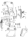
Fig. 1 is the exploded of hinge during decide at two ends according to an exemplary embodiment of the present invention.
Fig. 2 is a kind of double-action hinge that assembled, and it illustrates parts in the cam drive at place, two ends is fixed according to an exemplary embodiment of the present invention pellucidly.
Fig. 3 is the partial cut away side views of hinge component during double-action is according to an exemplary embodiment of the present invention made by oneself.
Fig. 4 is the side view that illustrates the fixed spring-loaded screw thread locking pin of arbitrary end of hinge during double-action is decided according to an exemplary embodiment of the present invention.
Fig. 5 is the schematic top view of another exemplary embodiment of the present invention, and it uses elastic component that hinge in fixed is biased into selected position, angle.
Fig. 6 is a schematic top view embodiment illustrated in fig. 5, shows the hinge of the position, angle that is forced into further stretching, extension elastic component.
Fig. 7 illustrates the leg-of-mutton schematic representation of the application of force when hinge is arranged as shown in Figure 6 point-blank.
Fig. 8 illustrates according to an exemplary embodiment of the present, when hinge is disposed to a side as shown in Figure 5, and the leg-of-mutton schematic representation of the application of force.
Fig. 9 is the exemplary support arm that can use with creative according to an exemplary embodiment of the present invention hinge.
Figure 10 is the side view of the hinge of two arm sections of interconnection, and showing according to an exemplary embodiment of the present invention, two different elastic components connect solid.
Figure 11 is the view of bottom side of the hinge component of Figure 10, shows according to an exemplary embodiment of the present invention the details that " off-centre " elastic component connects solid.
Figure 12 is the top view that spring terminal adjustment disk and selected spring position are shown.
Figure 13 illustrates the spring deflection under the rotation of parallelogram arm section according to an exemplary embodiment of the present invention.
Figure 14 illustrates according to an exemplary embodiment of the present invention with Figure 13 compares and is in spring deflection under the opposite rotation limit in the parallelogram arm section.
The hinge side spring that Figure 15 illustrates according to an exemplary embodiment of the present invention two different choice and adjusting is connected skew, to produce the effect of the end block of expectation to the hinge bias voltage respectively.
Figure 16 illustrates according to an exemplary embodiment of the present invention with hinge side offset axis and the combination of eccentric excursions axle, can be oriented to the effect of the end block of " right side " or " left side " structure to the hinge bias voltage with generation.
Figure 17 is the reversing bottom view of center arm hinge according to an exemplary embodiment of the present invention.
Figure 18 is the right side side view up of hinge according to an exemplary embodiment of the present invention.
Figure 19 is the inverted bottom perspective view of terminal leg hinge according to an exemplary embodiment of the present invention.
Figure 20 illustrates support arm according to an exemplary embodiment of the present invention.
Figure 21 illustrates hinge according to an exemplary embodiment of the present invention.
Figure 22 illustrates the hinge of the another exemplary embodiment according to the present invention.
Figure 23 A-F illustrates support arm according to an exemplary embodiment of the present invention, comprises the elastic element path.
Figure 24 illustrates according to the present invention the hinge of an exemplary embodiment again.
Figure 25 illustrates the hinge that has positive stop according to an exemplary embodiment of the present invention.
Figure 26 illustrates the side view of the hinge that has the friction clutch assembly according to an exemplary embodiment of the present invention.
Figure 27 illustrates the side view of the hinge that has the friction clutch assembly opposite with Figure 26 view according to an exemplary embodiment of the present invention.
Figure 28 illustrates the top view of the hinge that has the friction clutch assembly according to an exemplary embodiment of the present invention.
Figure 29 illustrates the bottom view of the hinge that has the friction clutch assembly according to an exemplary embodiment of the present invention.
Figure 30 illustrates friction clutch hinge component and barrel assemblies according to an exemplary embodiment of the present invention.
Figure 31 illustrates the cross-sectional view of friction clutch hinge component and barrel assemblies according to an exemplary embodiment of the present invention.
Figure 32 illustrates the spring and the friction clutch retaining belt of friction clutch assembly according to an exemplary embodiment of the present invention.
Embodiment
Fig. 1 illustrates the exploded of the fixed middle hinge of twin shaft according to an exemplary embodiment of the present invention.Hinge bearing rod 1 is that the axle center pivots between left and right sides end block 19 with pin 15 and 15a.Cam roller assembly 24 (comprising cam roller 9, roller base plate 10, axle 11, sleeve bearing 12 and flange bearing 13) inserts wellhole 22 and arc lobe plate 4 is connected to cam mounting plate 3, and cam mounting plate 3 is connected to end block 19.Lobe plate 4 thereby contact with cam roller 9, and since hinge angle be arranged in around the pin 15, peak on the lobe plate 4 and paddy rise and fall on cam roller 9, and cause that end block 19 correspondingly raises and falls.Flanged bearing 14 and 14a, preferably material is
Be used for reducing friction and allow end block to be easy to when hinge is swung around end block by means of cam action around pin 15 displacement vertically.In this embodiment, the payload of balanced support arm is transmitted by end block 19 and passes and roller 9 contacted lobe plates 4.Weight thereby supported by hinge bearing rod 1, and second cam roller on the bottom side of hinge 1 (in roller base plate 10a, not shown) leans against on the lobe plate 4a, this causes that equally hinge 1 changes along with the hinge angle with respect to end block 19 and raises and fall.The advantage of this layout provides the bias voltage action that cam causes, this can be proportional basically with the weight that is supported by support device, and " paddy " in the positioning cam plate.
Fig. 2 illustrates double action hinge assembly 200, and the cam-actuated fixed middle parts at place, two ends according to an exemplary embodiment of the present invention are shown pellucidly.Cam mounting plate 203 is connected to end block 219.When hinge 201 during around pin 215 swing, lobe plate 204 (being hidden in below the cam mounting plate 203) straddles on cam roller 209 so that the Feng Hegu of lobe plate causes end block 219 to raise and fall, and causes pin 215 displacement vertically in flanged bearing 214.Therefore gravity will tend to against roller 209 bias voltage lobe plates 204 and promote hinge 201 with thin " paddy " of positioning cam to thicker " peak ".Therefore, according to paddy and the peak design attitude along arc lobe plate, support arm section (not shown) can be biased to the expected angle orientation with respect to hinge 201.
Similar cam part on the bottom side of end block 219a and hinge 201, such as shown in lobe plate 204a and flanged bearing 214a, can be biased to complimentary positions equally so that the orientation of support arm section (not shown) will be tended to payload is maintained at desired locations.
Fig. 3 is the partial cut away side views of hinge component 300 during two according to an exemplary embodiment of the present invention actions are made by oneself.Hinge 301 is by pin 315 and 315a interconnect pivotally end block 319 and 319a. Cam roller assembly 324 and 324a be the corresponding wellhole in the insert hinge 301 preferably. Cam mounting plate 303 and 303a are connected to end block 319 and 319a respectively, and support interchangeable arc lobe plate 304 and 304a.Optionally the peak of moulding and the interaction between the paddy are tended to relevant end block is biased into the hinge orientation of being convenient to arrange support arm payload (not shown) on cam roller and the cam.Cam and cam roller can mainly interact based on gravity or these two parts can contact with each other powerfully.Spring-loaded screw thread locking pin (not shown among Fig. 3, but an one example shown in Figure 4 be locking pin 427.) can insert selected hole (from such as 325 or 325a the hole selected) with locking pin 326 or 326a in the engagement hinge 301, thereby make double action hinge the either side angle maintain static, to prevent the compound relative movement between relative end block and the hinge 310 and to cause simple pivot movement.If wish, also can maintain static both sides.
Fig. 4 is the partial side view of bias voltage hinge component 400 according to an exemplary embodiment of the present invention, shows spring-loaded screw thread locking pin so that arbitrary end of two action bias voltage hinges maintains static.Locking pin 427 inserts in a series of holes (only showing) in the cam mounting plates 403, so that when the locking hole in the hinge 401 426 during with locking pin 427 arrangements, fixedly the relative angle position of end block 419 and hinge 401.Preferably, these holes are arranged with arcuate structure.
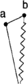
Fig. 5 is the schematic top view of linkage 500 according to an exemplary embodiment of the present invention, its adopt elastic component 528 will decide in hinge 501 be biased into select location.Hinge 501 pivots around pin 515.Skew pivot pin 529 is connected to hinge pivot pin 530 by elastic component 528.Hinge 501 is depicted as and is in the position that roughly forms beeline between the pin 529 and 530, and it will be the default position of hinge 501 with respect to end block 519 not having under the opposing force.
Fig. 6 is the schematic top view of linkage 500 according to an exemplary embodiment of the present invention, shows the hinge 501 of the position, angle of being forced to be in further stretching, extension elastic component 528.
Fig. 7 and 8 illustrates two leg-of-mutton schematic representation of the exemplary application of force when hinge is arranged as shown in Figure 6 point-blank.Fig. 8 illustrates the triangle of forces when hinge deviates to a side as shown in Figure 5.Notice that the distance among Fig. 7 is clearly less than the distance among Fig. 8.This explained this embodiment's of the present invention elastic component how to be used for hinge with Fig. 5 be biased into shown in the position.
Fig. 9 illustrates the exemplary support arm that can use with this creationary hinge.Hinge can link to base portion with support arm, and described base portion is 902 places in the position for example.Also can engage two arm sections 904,906 at contact 908 places.
Figure 10 is the side view that connects the hinge 1 of solid two arm sections of interconnection (not completely shown) by means of two different elastic components.End block 19 is connected to parallelogram support arm section (not shown) and interconnects to hinge 1 by means of joint pin 15,15a, so that the arm section pivots around hinge pivot center line 25,25a respectively.Spring terminal bay 34 is connected to end block 19 by locking screw 34a and is installed on the hinge side of pivot center line 25 with spring coupling shaft 29 with being offset, so that when end block 19 rotated with respect to hinge 1, spring coupling shaft 29 changed apart from the distance of the spring coupling shaft 35 of hinge installation.As shown, elastic component 28 is depicted as here and has the spring that extends butt hook 28a, and being used for bias voltage end block 19 provides the orientation of the shortest spring length-have the as shown end block of arranging with hinge 1 19 with the location.Below hinge 1, the skew spring connection of (away from hinge) is eccentric on the opposite side of axle 29a with respect to pivotal axis 25a, therefore and the spring 28 that is connected to hinge 1 by means of axle 30 will tend to bias voltage end block 19, become 90 orientations of spending with the either side of hinge 1 with the location.The combination that these two springs connect solid is biased into 90 relative orientations of spending with end block 19, and this can be forced to reorientate for the operation of supporting for " right side " or " left side " payload stablizes on either side.
Figure 11 is the detailed drawing of the bottom side of hinge 1 as shown in figure 10, shows according to an exemplary embodiment of the present invention " off-centre " elastic component and connects solid.Be installed on eccentric coupling shaft 29a on the mounting plate 34e that is connected to end block 19 from joint pin center line 25a (referring to Figure 10) towards end block 19 displacements, and thereby skew away from hinge 1.Elastic component 28 (being depicted as spring here) operatively is connected hinge installation shaft 30 with eccentric shaft 29a, and thereby to be biased into end block 19 and the parallelogram support arm (not shown) that connects thereof on the either side of the center line of hinge 1 be the orientations of 90 degree.The tensioning controlling mechanism can also be set, such as tensioned plate 40.The tensioned that provides certain limit by means of groove 33 and locking screw 31 in the depression of tensioned regulator plate 40 in the top of hinge 1 " is relaxed " by the arm in various degree that the payload of Different Weight causes with bias voltage.
Figure 10 and 11 illustrates the hinge means that second end block is connected to second end of hinge bodies and pivots around second axis therewith.These accompanying drawings show second biasing member, and it comprises the second hinge bodies end points on a side relative with the first hinge bodies end points for top and bottom on second elastic element, the second end block end points on second end block and the hinge bodies with first end and second end.The second end block end points and the second hinge bodies end points for top and bottom on the same side of hinge means.When second end block and hinge bodies were orientated as each other in 180 °, the second end block end points was positioned at than second axis further from the first hinge bodies end points.To install when regulating away from the wherein hinge bodies and second end block each other in 180 ° position, the distance between the second end block end points and the second hinge bodies end points is along with second end block reduces around the rotation of second axis with respect to hinge bodies.First end of second elastic element is connected to hinge bodies at the second hinge bodies end points place, and second end of second elastic element is connected to second end block at the second end block end points place, thereby second end block is biased into the wherein minimized position of tensioning of second elastic element with respect to the position of hinge bodies.In a preferred embodiment of the invention, when the hinge bodies and first end block were each other in 180 ° position therein, the distance between the second end block end points and the first hinge bodies end points increased when first end block rotates around first axle with respect to hinge bodies.
Figure 12 illustrates spring terminal adjustment disk 34 and the top view that can select spring shaft position 34d according to an exemplary embodiment of the present invention.The skew spring shaft 30 that spring 28 is installed hinge be installed on the off-axis 29 of coiling on 34 at select location 34c place and flexibly be connected, (regulating by means of ground, groove 34a and locking screw 34b location) is with bias voltage end block 19 on respect to the linear directional basically of hinge 1 in the embodiment shown.Figure 12 shows the spring shaft the selected position 34d that arc is arranged around spring terminal bay 34.But other solids that are noted that chosen position also within the spirit and scope of the present invention and different bias voltage structures can be provided.And, although terminal bay be shown in terminal bay in have joint pin 15 in the heart, it can be offset, with the bias voltage effect that forms expectation and the variation of tensioned.
Figure 13 is illustrated in exemplary embodiment medi-spring 28 of the present invention and is forced to deflection by what arm end block 19 and the rotation that is connected spring terminal adjustment disk 34 caused.(partly hide) because hinge pivot pin 15 and to be maintained at the vertical position, relatively little biasing force will promote end block 19 and be back to linear directional basically (in this example) with respect to hinge 1 around the hinge pivot pin center line.
Figure 14 illustrates end block 19 and is connected spring terminal bay 34, compare with position shown in Figure 13, they are forced to rotate to the relative angle limit with respect to hinge 1, so that spring 28 the hinge installation shaft 30 of bias voltage flexibly is connected with compare on the contrary with Figure 13 with offset axis at position 34c place, to be back to the linear orientation with hinge 1.
Figure 15 illustrates according to an exemplary embodiment of the present invention, and two hinge side springs differently selected and that regulate connect deviation post 34c produces different corresponding bias voltages between end block 19 and hinge 1 effect.Single tension spring 28 directly acts between the offset axis 29 (invisible), with they tractives flexibly toward each other, and thereby the directed end block 19 that they connect respectively with location desired angle relation.In this example, corresponding spring terminal bay 34 rotates to different directed by means of groove 34b and locking screw 34a, and is that spring shaft 29 (not shown) are selected different hinge side deviation posts from optional axle position 34d.Shown in select and corresponding adjusting tends to maintain the relative orientation of the end block 19 shown in this example.
Figure 16 illustrates hinge side offset axis 29d (hiding) combined with eccentric offset axis 29a, and to produce the effect that end block 19 is biased into hinge 1, its mode is for being oriented to " right side " or " left side " structure.Single elastic component (for example, have the spring 28 that extends butt hook 28a) hinge side spring skew link position 34c flexibly is connected with eccentric skew spring shaft 29a (being connected to end block 19 by means of mounting plate 34e), so that two end blocks 19 90 shown in side by side being biased into spent relative orientations.The characteristics that this spring connects solid are that end block 19 can be forced to be redirected in 180 degree, cause spring by crossing pivot center line 15a " intersect " center ", and thereby bias voltage end block 19 to keep opposite orientation with respect to hinge 1.
Figure 17 is the reversing bottom view of center arm hinge 1, shows the compressed-gas springs 36 that is connected between the 29a, axle 29a respectively on respective arms section end block 19 from hinge pivoted position 15 skew, thereby with position, angle shown in their bias voltages location.Therefore deviation post shown in the axle 29a will be moved to obtainable offing normal farthest mutually by the action of gas spring 36 and put, if if be not subject to mechanical interference and displacement symmetry relatively, so just will realize balance and reach gas spring center line 36 roughly with hinge bodies 1 coplane.This will cause that end block 19 effectively keeps its relative angle position in varying degrees, depend on the spring performance of gas spring 36 and the amplitude and the direction of the offset distance between axle 29a and the hinge centring point 15.
Figure 18 is the right side side view up of the elastic component 36 of Figure 17, further shows the relation between the position of offset axis 29a, and the center hinge between the arm end block 19 1.
Figure 19 is the elevated bottom perspective view of putting upside down of terminal leg hinge 1, show between the eccentric shaft 29a and the compressed-gas springs 36 hinge pivoted position skew of being connected on the arm section end block, with hinge bodies 1 relevant relative regularly spring shaft position 29, but skew on mounting bracket 38.As show that the action of pressure spring 36 forces a 29a and axle 29 to separate, so that end block 19 presents about position, angle roughly shown in the plane of hinge bodies 1.As shown, the relative orientation of hinge bodies 1 and principal arm mounting bracket 37 is not subjected to the influence of the action of gas spring 36, because axle 29 is depicted as and is fixedly connected to hinge bodies 1 and is correlated with to angle with it, hinge bodies 1 can freely be swung around hinge pivot pin center line 15a in the present embodiment.
Gas spring also can be connected to first end block by first end with gas spring, departs from respect to the spin axis of end block and hinge bodies, and the end points that the other end of gas spring is connected on the hinge bodies is used.This is with respect to hinge bodies bias voltage end block.Be connected at gas spring under the point at each end block place, with opposite on the hinge bodies, not only with respect to hinge bodies bias voltage end block, but also with end block bias voltage relative to each other.For two end blocks of bias voltage respectively, an end block on the side of device can adopt a gas spring and second gas spring can be used for second end block on the opposite side of device.All bias systems described here are all like this.Dissimilar bias systems also can be used for every end place of hinge bodies.
To illustrate that also the skew support can be used for end block with biasing member in all cases and be positioned directly not to be in position on hinge bodies or the end block.
Figure 20 illustrates the support arm that has another bias mechanism according to an exemplary embodiment of the present invention.Support arm 600 comprises the near-end support arm section 602 that is hinged to far-end support arm section 604 by hinged system 606.Near-end support arm section 602 has first and second end blocks 630,632.Far-end support arm section 604 has end block 634,636.Near-end support arm section 602 is pivotally connected to hinged system 606 at near-end centring point 608 places.Far-end support arm section 604 is pivotally connected to hinged system 606 at far-end centring point 610 places.Near-end support arm section 602 and far-end support arm section 604 are that support arm 600 " promotes section ", are configured to have around near-end centring point 608 and far-end centring point 610 motion of the axial motion of being substantially perpendicular to.
Tension element 616 extends through shoulder hinge 612, near-end support arm section 602, hinged system 606 and far-end support arm section 604.The form of tension element can be for example other oblong objecies of spring, rope, cable, rope, flat element (flat members) and energy as enforcement described here.Tension element can be flexible or stiff.In this exemplary embodiment, tension element 616 has the end points in shoulder hinge 612 and far-end support arm section 604.Need explanation, when end points here be described as being in parts " in " time, it is included on the surface of these parts, and when end points here be described as being in parts " on " time, it is included on these parts and in these parts.And the tension element that extends " going into " parts is not limited to it in this components interior, and can extend along external path.Tension element 616 is arranged in around the rotatable axle 618, and this axle 618 is positioned between near-end centring point 608 and the far-end centring point 610 and is substantially parallel with them.Need explanation, word " end points " is not to refer to a single point, but can be little zone.
Near-end support arm section 602 also is pivotally connected to shoulder hinge 612.Shoulder hinge 612 can be connected to for example fixed support, such as wall or post for instance, perhaps is anchored on loose impediment, such as the support on the car.
Far-end support arm section 604 also is pivotally connected to base portion connected element 614.Base portion connected element 614 also can be connected to various types of equipments and equipment holder.Word used herein " equipment " very broadly uses, and comprises for example instrument, photographic camera and other objects.
Figure 21 shows hinged system according to an exemplary embodiment of the present invention.Hinged system 702 is pivotally connected to near-end support arm section 704 at near-end centring point 708 places.Near-end support arm section 702 comprises end block 732.Hinged system 702 also is connected to far-end support arm section 706 at far-end centring point 710 places.Far-end support arm section 704 comprises end block 734.The axle 718 zones that are positioned between the centring point 708,710 in and substantially parallel with them.Tension element 716 is arranged in around the axle 718.First end of tension element 716 passes the opening 724 in the hinge bodies 726, and second end passes the opening 728 in the hinge bodies 726.The first tension element end passes the hole 730 in the end block 732 then, and the second tension element end passes the hole 740 in the end block 734.Tension element 716 is anchored in end points 720 places in the near-end support arm section end block 732 and the end points place in the far-end support arm section end block 734.Alternatively, single tension element can use first end that is anchored on anchor point 742 places for having.Tension element passes the hole 730 in the end block 732 then, pass hole 724 and enter hinge bodies 726, threaded shaft 718, pass hole 728 and leave hinge bodies 726, pass hole 740 and enter end block 734, pass anchor point 744 then and unroll, pass hole 740,728,724 and 730 then and return and be anchored on anchor point 742 places.Tension element 716 energy tractives are to expecting tension force and being anchored on anchor point 742,744 places, so that the selected bias voltage and the range of movement of support arm to be provided.Be noted that biased position can refer to middle surely position or similar statement all the time, yet this is not to mean that arm is in two specific mid points.Tension element 716 can lead so that the range of movement of expectation to be provided on the either side of support arm.
Figure 22 illustrates the hinge of the another exemplary embodiment according to the present invention.First end of tension element 816 is anchored in end points 720 places in the near-end support arm end block 732.Tension element 816 passes the opening 730 in the end block 732, passes opening 724 then and enters hinge bodies 726 and threaded shaft 718.Tension element 816 passes hole 724 then and leaves hinge bodies 726 and pass hole 730 and enter end block 732.Second end of tension element 816 is anchored in end points 720 places in the near-end support arm end block 732 then.Tension element 816 energy tractives are to expecting tension force and being anchored on anchor point 742 places, so that the selected bias voltage and the range of movement of support arm to be provided.Tension element 816 can lead so that the range of movement of expectation to be provided on the either side of support arm.
Figure 23 A-F illustrates the support arm that comprises the tension element path according to an exemplary embodiment of the present invention.Support arm 100 comprises near-end support arm section 102 and far-end support arm section 104.Near-end support arm section 102 is pivotally connected to hinged system 106 at centring point 108 places.Far-end support arm section 104 is pivotally connected to hinged system 106 at centring point 110 places.Support arm 100 among Figure 23 A comprises first tension element 112 and second tension element 114.Tension element 112,114 is arranged on the opposite side of support arm 10.In this specific embodiment, tension element 112,114 is not arranged in around the axle 116 of being presented between near-end centring point 108 and the far-end centring point 110.In Figure 23 A-F, the tie point of tension element and all the other support arm structures is represented so that approximate location to be shown with triangle, and is not meant that it is truly describing of tie point.Figure 23 A illustrates the tie point at near-end support arm end block 118,120 places and far-end support arm end block 122,124 places.The end points that is used for tension element 112,114 is at far-end end block 124 places, and be positioned at, near or above shoulder hinge 126 (at, near or beyond).Use on the side of support arm 100 from near-end to far-end, cross then support arm 100 and at last on the opposite side of support arm 100 the single tension element of paths arrangement from far-end to near-end can realize similar the structure.
Figure 23 B illustrates the support arm 100 with tension element 128,130.In this embodiment, tension element 128 and 130 each threaded shaft 116 all.They are also around the axle 132 in the shoulder hinge 132.Tension element 128,130 is arranged on the opposite side of support arm 100.Circular path cause tension element 128 and 130 each in its entire path, still be on the side of support arm 100.Need to prove that tension element 128,130 is threaded shaft 116 and/or 132 partly, they will intersect so that a part of path of a single tension element can stride across a side of support arm 100 in the case, and a part can stride across opposite side.Figure 23 B illustrates the tie point at near-end support arm end block 118,120 places and far-end support arm end block 122,124 places.The end points that is used for tension element 112,114 is a far-end end block 124, and be positioned at, near or above shoulder hinge 126.
Figure 23 C-F illustrates the support arm 100 with various tension element end points and path.Figure 23 C comprises first end points that has at shoulder hinge 126 places, at the tie point at end block 118 places and at the tension element of second end points at end block 120 places.
Figure 23 D comprises first end points that has at near-end support arm section end block 118 places, in the connection at end block 120 places and at the tension element of second end points at far-end support arm section end block 122 places.
Figure 23 E comprises first end points that has at near-end support arm section end block 120 places, at the tension element of second end points at far-end support arm section end block 122 places, thereby stride across hinged system 106.
Figure 23 F illustrates the support arm 100 with a kind of tension element, and this tension element has at first end points at near-end support arm section end block 120 places, in the connection at far-end support arm section end block 122 places and at second end points at end block 124 places.
Tension element need not to extend on the plane parallel with support arm.When striding across the plane that is not parallel to support arm, tension element can influence the vertical and horizontal motion of support arm.Be not parallel at tension element under the situation of horizontal support arms section, its outward appearance length will raise and change along with arm.If this tension element alternatively is stiff, it will limit the scope of vertical motion.It can be used to allow the effective length of vertical motion to change if it crosses at least one transverse joint, and it will have influence to the total vertical range as the lateral attitude function so.If it is an elastic element, it can help or be unfavorable for lifting with the lateral attitude variation.
Although axle is being shown in Figure 23 A-F between far-end and near-end centring point, among each embodiment of the present invention not being must be such axle.This axle when having, can be that fix or pivotable.Numerous structures of tension element all within the scope of the invention.When having two or more tension elements, some or all of tension elements can extend to same endpoints basically and defer to substantially the same path, and perhaps path and end points can change.By using a plurality of tension elements, the intensity of this system or level of integration can increase, and the elasticity of composition element or tension force can be different with the situation of discrete component.
Two or more tension elements can use to having different length and/or elasticity in various degree.These structures can provide different biasing forces for the difference in the range of movement of arm.For example, if in a structure, use two tension elements so that first element is only meshed in initial arm motion, and the motion of arm subsequently engagement second tension element, initial arm motion is with biased one first amount, and the motion of arm subsequently is with different amount of bias voltage.Thereby for example, arm can more freely motion and so not free on the remaining part of scope in little initial range.
A plurality of tension elements that each arm section or hinge also can be anchored on the difference place of arm and stride across different length by use are bias voltage differently.
Figure 24 illustrates hinge according to an exemplary embodiment of the present invention.Hinge bodies 802 is pivotally connected to end block 804 at centring point 806 places.Hinge bodies 802 is pivotally connected to end block 808 at centring point 810 places.End block 804,808 can be connected to the section of support arm.Torsion spring 812 is arranged in around the centring point 806 and has first end of contact end block 804 and second end of engagement shaft 816, thereby bias voltage is connected the parts at centring point 806 places to rotate in the desired motion scope.Concrete scope will depend on the location and the spring constant (torsion coefficient) thereof of torsion spring 812 at least in part.
The range of movement of example is about 0 ° to about 200 °.
Left-handed or dextrorotation torsion spring can be installed and control the bias voltage direction.
Figure 25 illustrates the hinge that has positive stop according to an exemplary embodiment of the present invention.Rotary stopper block 750 is mounted to hinge bodies 726 with the degree of rotation of restriction end block 732 (and thereby near-end support arm section 704) with respect to hinge bodies 726 by screw 752,754.Rotary stopper block 750 comprises that first block component, 756, the first block components 756 comprise second block component 758 that can slide with respect to first block component 756.In specific embodiments of the invention, first block component 756 be hollow and second block component 758 disposed therein slidably.
Screw 752,754 is anchored on second block component 758 in first block component 756 at the desired locations place.The position of second block component 758 can towards with regulate away from the point of contact on the end block 732 of near-end support arm section 702 760.When second block component 758 ran into point of contact 760, arm section 702 was in maximum with respect to the rotation of hinge bodies 726.
Similarly, the second rotary stopper block 762 is mounted to hinge bodies 726 with the degree of rotation of restriction end block 734 (and thereby far-end support arm section 706) with respect to hinge bodies 726 by screw 764,766.Rotary stopper block 762 comprises that first block component, 768, the first block components 768 have second block component 770 that can slide with respect to first block component 768.In specific embodiments of the invention, first block component 768 is hollow, and second block component 770 is disposed therein slidably.
Other rotary stopper blocks and associated adjustment mechanism within the scope of the invention, as long as they are used for the range of movement of restricted arm section with respect to hinge bodies.Positive stop also can be uncontrollable.
The rotary stopper block also can be fastened to support arm by the equipment outside the screw.Welding, glue and soldering (solder) are to be used for the rotary stopper block is fastened to the example of other mechanisms of support arm.
Be noted that also the rotary stopper block can be fastened to support arm, for example on end block, and point of contact is in hinge bodies or be connected on this element.
In exemplary embodiment of the present invention, positive stop allow from about 0 ° to about 200 ° range of movement.Exemplary rotating range in addition comprises about 15 ° to about 180 °, and about 20 ° to about 140 °.
Figure 26-33 illustrates according to single cod of having of further embodiment of this invention and the quick hinge component that discharges cylinder assembly.Figure 26 is that left side view and Figure 27 are right side views, because the reversible attribute of hinge component, with respect to being nonrestrictive relativity word about this hinge use, this will discuss in more detail below.Figure 28 and 29 illustrates the top view of closed according to an exemplary embodiment of the present invention and hinge-opening assembly.Word " top " and " bottom " also only are the relativity words, rather than restrictive.
Proximal arm supporting section 140 is connected to far-end support arm section 142 by hinge component 144.Hinge component 144 comprises near-end hinge section 156 and far-end hinge section 158.Proximal arm supporting section 140 comprises end block 146.Far-end support arm section 142 comprises end block 148.
Figure 30-33 illustrates the details of hinge component 144.Hinge component 144 comprises joint pin 160, and it can be a quick-release latch.Joint pin 160 is connected to far-end hinge section 158 with near-end hinge section 156 pivotally.Torsion spring 162 is arranged in around the friction clutch cylinder 172, shown in Figure 31 and 33.Friction clutch band 164 is arranged in around the friction clutch cylinder 172.Friction clutch band 164 can be by regulating at the friction clutch regulating equipment 166 that shown in Figure 30 and 33 is winged screw 168.If can from Figure 33, see, the friction clutch band is regulated the radial force that winged screw 168 increases 164 pairs of friction drums 172 of friction clutch band, makes near-end hinge section 156 and far-end hinge section 158 around the required payload of hinge component centring point 154 rotations thereby increase.Figure 32 illustrates by holder 174 fastening torsion spring 162 and friction clutch band 164.Other holder structures also are in the scope of the present invention, as long as they are anchored in the hinge component 144 torsion spring 162 and friction clutch band 164 so that the resistance that they can provide hinge section 156,158 to rotatablely move.
Figure 30 and 31 illustrates proximal cylinder assembly 180 and distal cylinder assembly 182, and they are designed to quick release in this embodiment.Proximal cylinder assembly 180 is connected near-end hinge section 156 rigidly with near-end support arm section 140.Distal cylinder assembly 182 is connected far-end hinge section 158 rigidly with far-end support arm section 142.
Figure 30 and 31 also illustrates the details of cylinder assembly 180,182.Proximal cylinder assembly 180 comprises the relative installation cylindrical shell 184,186 that wherein has proximal cylinder locking axle 197.Near-end locking screw 188,190 threadably is engaged in the cylindrical shell locking axle 197.Although being installed, cylindrical shell extension spring 192a-b is arranged in the open end that cylindrical shell 184,186 is installed.Extension spring can be included on the installation cylindrical shell or install on each of cylindrical shell relatively.
When locking screw 188,190 was driven toward each other, relative installation cylindrical shell 184,186 can be against extension spring 192a-b compression to allow whole assembly to see that in Figure 31 for example the cooperation aperture " laterally " from near-end support arm section 142 and hinge component 144 removes.This provides arm section " discharging fast " mechanism from the hinge component dismounting.
Dog screw (Dog screws) 194a-b can be used to aim at the installation cylindrical shell.
In embodiment shown in Figure 31, distal cylinder assembly 182 has the parts identical with proximal cylinder assembly 180, cylindrical shell 185,187, locking screw 180,191 is installed relatively, cylindrical shell extension spring 193a-b and dog screw 195a-b are installed.
Cylinder assembly 180,182 can perhaps can use with other assemblies with using such as the friction clutch assembly shown in Figure 30-33.Similarly, the friction clutch assembly can use with the assembly outside the cylinder assembly 180,182.Hinge component described here can be used between the support arm section or support arm section and another parts, between fixed support or tool retainer.
Embodiments of the invention can be embodied as has parts alternative or that put upside down.For example, shoulder hinge or base portion connected element can be connected to near-end or member supports arm section.The rotary stopper block can be used to only limit the motion of near-end support arm section or far-end support arm section, and perhaps block can be used for limiting the motion of these two arm sections.
Various bias systems described here and equivalent thereof can be separately or combination with one another ground use.For example, hinge bodies can be used a bias system to be connected to first end block and use a different bias system to be connected to second end block.
Hinge means of the present invention can be functionally connected to support arm, and such as arm shown in Figure 9, it has the section of two parallelogram shape.In this illustrated embodiment of the present invention, these two arm sections can by between hinge bodies and arm section or the hinge means that between hinge bodies and each arm section, has a biasing member connect.If biasing member is used for every end place of hinge, they can be the biasing members of identical or different type.Need explanation, specification, comprise that the word " end block " that uses in the claim can mean the support equipment body.In certain embodiments of the present invention, supporting part, such as arm, but can via end block be functionally connected to hinge bodies or direct function be connected to hinge.Also the word " arm section " that here uses can comprise end block and various miscellaneous part.
Single parallelogram section also can constitute support arm, and is functionally connected to hinge bodies.
Embodiments of the invention also comprise the method for using equipment support system, support arm and hinge described here and equivalent thereof to come support equipment.
Described each embodiment of the present invention, each has the various combination of element and step.The invention is not restricted to disclosed specific embodiment, and can comprise the various combination of disclosed element and step.
Though the present invention describes by means of exemplary embodiment, other advantages and modification are obviously to those skilled in the art.Therefore, the present invention is shown in it is not limited to aspect more wide in range and detail described here.Modification can be made not deviating under the spirit and scope of the present invention.So the present invention should be not limited to concrete exemplary embodiment, but in whole spirit and scope of claims and equivalents thereof, make an explanation.
Claims (46)
1. support arm, it comprises:
Near-end support arm section;
Far-end support arm section;
Hinged system, it has at near-end centring point place and is pivotally connected to the near-end of near-end support arm section, and is pivotally connected to the far-end of far-end support arm section at far-end centring point place;
Tension element with first end and second end, first end of tension element extends into near-end support arm section or far-end support arm section and is anchored on above it or the end points place of top, and second end of tension element extends into near-end support arm section or far-end support arm section and is anchored on above it or the end points place of top, thereby tension element is with near-end support arm section and far-end support arm section one or both are with respect to the hinged system bias voltage.
2. support arm as claimed in claim 1 comprises the axle that is arranged essentially parallel in near-end centring point and far-end centring point and the zone between near-end centring point and far-end centring point, and wherein said tension element is arranged as at least in part around this axle.
3. support arm as claimed in claim 1, wherein first end of tension element extends into near-end support arm section and is anchored on above the near-end support arm section or the end points place of top, and second end of tension element extends into far-end support arm section and is anchored on above the far-end support arm section or the end points place of top.
4. support arm as claimed in claim 3, wherein first end of tension element is anchored on the end points place on the near-end support arm section, and second end of tension element is anchored on the end points place on the far-end support arm section.
5. support arm as claimed in claim 1, wherein second end of first end of tension element and tension element is anchored on above the identical support arm section of near-end support arm section and the selection of far-end support arm section or the end points of top.
6. support arm as claimed in claim 1, wherein first end of tension element is anchored on the end points place on the shoulder hinge, and wherein the shoulder hinge is pivotally connected to near-end support arm section at the place, end relative with the near-end centring point.
7. support arm as claimed in claim 1, wherein second end of first end of tension element and tension element is anchored on the end points place on the shoulder hinge, and wherein the shoulder hinge is pivotally connected to near-end support arm section at the place, end relative with the near-end centring point.
8. support arm as claimed in claim 1, wherein second end of tension element is anchored on the end points place on the base portion connected element, and wherein the base portion connected element is pivotally connected to far-end support arm section at the place, end relative with the far-end centring point.
9. support arm as claimed in claim 1, wherein second end of first end of tension element and tension element is anchored on the end points place on the base portion connected element, and wherein the base portion connected element is pivotally connected to far-end support arm section at the place, end relative with the far-end centring point.
10. support arm as claimed in claim 1, wherein tension element is flexible.
11. support arm as claimed in claim 1, wherein tension element is stiff.
12. support arm as claimed in claim 1, its axis is rotatable.
13. support arm as claimed in claim 1 comprises two tension elements, wherein these two tension elements extend to substantially the same end points and defer to substantially the same path.
14. support arm as claimed in claim 1 comprises two tension elements, wherein these two tension elements have different length.
15. support arm as claimed in claim 1 comprises two tension elements, wherein these two tension elements have the different elasticity of degree to each other.
16. support arm as claimed in claim 1 comprises second tension element with first end and second end, wherein first end of first tension element is anchored on the end points place different with first end of second tension element.
17. as the support arm of claim 16, wherein second end of first tension element is anchored on the end points place different with second end of second tension element.
18. support arm as claimed in claim 1, comprise second tension element with first end and second end, wherein first end of first tension element is anchored on the end points place on the parts different with first end of second tension element of support arm, and wherein said parts comprise near-end support arm section, far-end support arm section, base portion connected element, shoulder hinge and base portion.
19. support arm as claim 18, comprise second tension element with first end and second end, wherein second end of first tension element is anchored on the end points place on the parts different with second end of second tension element of support arm, and wherein said parts comprise near-end support arm section, far-end support arm section, base portion connected element, shoulder hinge and base portion.
20. support arm as claimed in claim 1 comprises two tension elements, wherein tension element is deferred to the path that differs from one another.
21. as the support arm of claim 20, wherein tension element is arranged on the opposite flank of support arm.
22. support arm as claimed in claim 1 comprises single tension element, a part of path of this tension element is on a side of support arm, and a part of path is on the opposite side of support arm.
23. support arm as claimed in claim 1, wherein the path of tension element is not parallel to the vertical center line of arm section.
24. support arm as claimed in claim 1 also comprises one or more rotary stopper blocks.
25. the method for a supporting object, it comprises:
Object is connected to support arm according to claim 1;
Regulate hinged system support arm is biased into select location or position range.
26. a support arm, it comprises:
Near-end support arm section;
Far-end support arm section;
Hinged system, it has at near-end centring point place and is pivotally connected to the near-end of near-end support arm section, and is pivotally connected to the far-end of far-end support arm section at far-end centring point place;
At least one rotary stopper block, it is fastened to hinged system, with restriction near-end support arm section, far-end support arm section or the two degree of rotation with respect to hinged system.
27. as the support arm of claim 26, rotary stopper block can regulate wherein.
28. as the support arm of claim 27, wherein the rotary stopper block comprises:
First block component;
With respect to first block component, second block component slidably;
First block component is fastened to hinged system, so that second block component can towards or slide away from the point of contact on one of near-end support arm section or far-end support arm section, wherein when second block component ran into point of contact, the arm section was in maximum with respect to the rotation of hinged system; And
Second block component is anchored on controlling mechanism in a plurality of positions with respect to first block component.
29. as the support arm of claim 26, wherein rotate be restricted to about 0 ° to about 200 ° scope.
30. as the support arm of claim 28, wherein first block component is hollow and second block component can slide therein.
31. the method for a supporting object, it comprises:
Object is connected to the support arm of constructing according to claim 26;
Regulate the rotary stopper block with restriction near-end support arm section, far-end support arm section or the two degree of rotation with respect to hinged system.
32. a support arm, it comprises:
Near-end support arm section;
Far-end support arm section;
Hinged system, it has hinge bodies, hinge bodies have near-end centring point place be pivotally connected to near-end to near-end support arm section, far-end centring point place be pivotally connected to the far-end of far-end support arm section and be arranged as be arranged essentially parallel to near-end and far-end and be in the near-end centring point and the far-end centring point between the zone in axle; And
Be arranged in the near-end torsion spring around the near-end centring point, and wherein the near-end torsion spring first end with spool contact, and second end of near-end torsion spring contacts with the near-end supporting section, thus bias voltage near-end support arm section is with respect to the range of movement of hinge bodies.
33. the support arm as claim 32 also comprises:
Be arranged in the far-end torsion spring around the far-end centring point, and wherein the far-end torsion spring first end with spool contact, and second end of far-end torsion spring contacts with the far-end supporting section, thus bias voltage far-end support arm section is with respect to the range of movement of hinge bodies.
34. as the support arm of claim 31, wherein range of movement about 0 ° to about 200 ° scope.
35. the method for a supporting object, it comprises:
Object is connected to support arm according to claim 31; And
Bias voltage near-end support arm section and far-end support arm section are with respect to the range of movement of hinge bodies.
36. a support arm, it comprises:
Near-end support arm section;
Far-end support arm section;
Hinge component with near-end hinge section and far-end hinge section, the near-end hinge section is pivotally connected to the far-end hinge section at friction clutch centring point place, and the friction clutch centring point is the part of friction clutch assembly; And
The near-end hinge section, its near-end centring point place at the near-end hinge section end place relative with the friction clutch centring point is connected to near-end support arm section rigidly; And
The far-end hinge section, its far-end centring point place at the far-end hinge section end place relative with the friction clutch centring point is connected to far-end support arm section rigidly.
37. as the support arm of claim 36, wherein the friction clutch assembly also comprises:
Joint pin;
Be arranged at least a portion friction clutch cylinder on every side of joint pin circumferentially;
Be arranged in friction clutch cylinder torsion spring on every side; And
Holder, its first end with torsion spring is fastened to the near-end hinge section, and second end of torsion spring is fastened to the far-end hinge section, thereby provides rotating force on near-end and far-end hinge section;
Be arranged in friction clutch cylinder friction clutch band on every side, it can be applied to power the friction clutch cylinder;
The friction clutch regulating equipment, it is incorporated into the friction clutch assembly functionally to regulate the power of friction clutch band on friction drum.
38. as the support arm of claim 37, wherein the friction clutch regulating equipment comprises:
The power parts, its structure comes on the direction of friction drum power to be put on the friction clutch band, to change the power of friction clutch band on friction drum when the power component movement.
39. as the support arm of claim 38, wherein the power parts are screws, it is arranged into the tapped bore in the hinge component, to change the power of friction clutch band on friction drum when the screw motion passes in and out hinge component.
40. support arm as claim 36, in wherein a plurality of connections at least one is cylinder assembly, described connection comprises connection between near-end support arm section and the near-end hinge section and the connection between far-end support arm section and the far-end hinge section, and this cylinder assembly comprises:
The first installation cylindrical shell of longitudinally arranging each other and second is installed cylindrical shell;
Longitudinally arrange and longitudinally be arranged in first each other the cylindrical shell and the second first locking screw and the second locking screw of installing in the cylindrical shell are installed, wherein the locking screw can by towards or vertically drive away from each other, thereby compression or separate cylindrical shell is installed;
First at least one of installing in the cylindrical shell and the second installation cylindrical shell has the extension spring of the open end that is arranged in this installation cylindrical shell; And
Wherein when the first and second installation cylindrical shells compressed toward each other, cylinder assembly is installed can be removed slidably from hinge component and support arm section, thereby with the be connected disconnection of hinge component with the support arm section.
41. as the support arm of claim 39, wherein each installation cylindrical shell has the extension spring that is arranged in its open end.
42. as the support arm of claim 37, wherein the friction clutch regulating equipment can regulate make near-end hinge section and far-end hinge section around the friction clutch centring point can move freely from hinge section part to they do not rotate required power in the scope of removable part basically.
43. as the support arm of claim 40, wherein hinge component is configured to put upside down from right to left.
44. the method for a supporting object, it comprises:
Object is connected to support arm according to claim 35; And
Regulate the friction clutch assembly support arm is biased into select location or position range.
45. an installation cylinder assembly that is used in conjunction with first and second parts, it comprises:
The first installation cylindrical shell of longitudinally arranging each other and second is installed cylindrical shell;
Longitudinally arrange and longitudinally be arranged in first each other the cylindrical shell and the second first locking screw and the second locking screw of installing in the cylindrical shell are installed, wherein the locking screw can by towards or vertically drive away from each other, thereby compression or separate cylindrical shell is installed;
First at least one of installing in the cylindrical shell and the second installation cylindrical shell has the extension spring of the open end that is arranged in this installation cylindrical shell; And
Wherein when the first and second installation cylindrical shells compressed toward each other, cylinder assembly is installed can be removed slidably from first and second parts, thereby the connection of these parts is disconnected.
46. as the installation cylinder assembly of claim 45, wherein each installation cylindrical shell has the extension spring that is arranged in its open end.
Applications Claiming Priority (3)
| Application Number | Priority Date | Filing Date | Title |
|---|---|---|---|
| US10140608P | 2008-09-30 | 2008-09-30 | |
| US61/101,406 | 2008-09-30 | ||
| PCT/US2009/058783 WO2010039707A1 (en) | 2008-09-30 | 2009-09-29 | Biased hinge for equipoising support equipment |
Publications (1)
| Publication Number | Publication Date |
|---|---|
| CN102165242A true CN102165242A (en) | 2011-08-24 |
Family
ID=42073835
Family Applications (1)
| Application Number | Title | Priority Date | Filing Date |
|---|---|---|---|
| CN2009801381972A Pending CN102165242A (en) | 2008-09-30 | 2009-09-29 | Biased hinge for equipoising support equipment |
Country Status (7)
| Country | Link |
|---|---|
| US (2) | US8801319B2 (en) |
| EP (1) | EP2344806B1 (en) |
| JP (1) | JP2012504218A (en) |
| CN (1) | CN102165242A (en) |
| AU (1) | AU2009298701A1 (en) |
| CA (1) | CA2737285C (en) |
| WO (1) | WO2010039707A1 (en) |
Cited By (3)
| Publication number | Priority date | Publication date | Assignee | Title |
|---|---|---|---|---|
| CN105425513A (en) * | 2015-12-01 | 2016-03-23 | 中国科学院沈阳自动化研究所 | Interface board structure used for connecting panorama cameras on space probe with rotary table |
| CN107322636A (en) * | 2017-09-01 | 2017-11-07 | 深圳龙海特机器人科技有限公司 | Flexible joint and revolution folding arm |
| CN108368715A (en) * | 2015-10-19 | 2018-08-03 | 伊利诺斯工具制品有限公司 | Include the door handle of double hinged sound attenuating tabs features |
Families Citing this family (26)
| Publication number | Priority date | Publication date | Assignee | Title |
|---|---|---|---|---|
| US8142083B2 (en) * | 2008-11-14 | 2012-03-27 | Brown Garrett W | Extendable camera support and stabilization apparatus |
| US8506180B2 (en) | 2008-11-14 | 2013-08-13 | Garrett W. Brown | Extendable camera support and stabilization apparatus |
| WO2010056968A1 (en) * | 2008-11-14 | 2010-05-20 | Brown Garrett W | Extendable camera support and stabilization apparatus |
| US9534730B2 (en) | 2010-08-26 | 2017-01-03 | Garrett W. Brown | Multi-arm gimbal system |
| US9095981B2 (en) * | 2012-01-11 | 2015-08-04 | Garrett W. Brown | Load and torque resistant caliper exoskeleton |
| WO2013158490A1 (en) * | 2012-04-15 | 2013-10-24 | Brown Garrett W | Lifting extension mount assembly for equipoising arms |
| US9049925B1 (en) * | 2013-01-14 | 2015-06-09 | Russell L. Winchester | Tool mounting structure |
| US9416912B2 (en) * | 2013-03-15 | 2016-08-16 | Lilitab LLC | Wall mount with configurable stops |
| FR3016821B1 (en) * | 2014-01-29 | 2019-08-02 | Robotiques 3 Dimensions | EXOSQUELETTE WITH FRONT PORT AND METHOD OF USING SUCH AN EXOSQUELET. |
| US20150308618A1 (en) * | 2014-03-12 | 2015-10-29 | Koncept Innovators, LLC. | Vest-mounted gimbal support, and a method for its use |
| US20160010376A1 (en) * | 2014-07-10 | 2016-01-14 | Biofit Engineered Products | Foldable table |
| US10024484B2 (en) | 2014-11-16 | 2018-07-17 | Brown Garrett W | Tensile parallelogram arm |
| WO2016112452A1 (en) | 2015-01-14 | 2016-07-21 | Centre For Imaging Technology Commercialization (Cimtec) | A counterbalance apparatus and/or method for supporting a load |
| US9802307B2 (en) * | 2015-09-02 | 2017-10-31 | Lockheed Martin Corporation | Locking intermediate link for a tool arm assembly |
| US10208891B2 (en) * | 2016-05-25 | 2019-02-19 | Myerchin Enterprises, Inc. | Multi-arm display anti-toppling mechanism |
| US10501973B2 (en) * | 2016-06-14 | 2019-12-10 | Microsoft Technology Licensing, Llc | Hinge with free-stop function |
| US10301858B2 (en) * | 2016-06-14 | 2019-05-28 | Microsoft Technology Licensing, Llc | Hinge mechanism |
| US10845000B2 (en) * | 2016-10-21 | 2020-11-24 | Colebrook Bosson Saunders (Products) Limited | Display support system |
| WO2018200726A1 (en) | 2017-04-25 | 2018-11-01 | Life Door, Inc. | Door closing device |
| US10808447B2 (en) | 2017-04-25 | 2020-10-20 | Masonite Corporation | Emergency door closing device |
| US11118729B2 (en) * | 2017-06-09 | 2021-09-14 | Teknion Limited | Adjustable counterbalancing display support |
| US11174664B2 (en) | 2018-03-20 | 2021-11-16 | Masonite Corporation | Door positioning system |
| CA3095349A1 (en) * | 2018-03-30 | 2019-10-03 | Masonite Corporation | Compact door closer |
| CN109202948B (en) * | 2018-11-14 | 2024-02-20 | 上海交通大学 | Force control mechanical claw |
| IT202100001766A1 (en) * | 2021-01-28 | 2022-07-28 | Innova S P A | HANDLING DEVICE FOR A CAMERA AND RELATED OPTICAL INSPECTION ASSEMBLY |
| IT202100001775A1 (en) * | 2021-01-28 | 2022-07-28 | Innova S P A | ACTUATOR FOR ACTIVATION OF A DEVICE FOR THE HANDLING OF AT LEAST ONE CAMERA |
Family Cites Families (52)
| Publication number | Priority date | Publication date | Assignee | Title |
|---|---|---|---|---|
| US2090439A (en) * | 1932-07-04 | 1937-08-17 | Carwardine George | Equipoising mechanism |
| US2076446A (en) * | 1934-02-10 | 1937-04-06 | Terry Herbert & Sons Ltd | Equipoising mechanism |
| US3774873A (en) | 1971-11-24 | 1973-11-27 | Jacobsen As J | Equipoised arm assembly |
| USRE32213E (en) | 1974-09-16 | 1986-07-22 | Equipment for use with hand held motion picture cameras | |
| US4017168A (en) | 1974-09-16 | 1977-04-12 | Brown Garrett W | Equipment for use with hand held motion picture cameras |
| US4208028A (en) * | 1974-09-16 | 1980-06-17 | Garrett Brown | Support apparatus |
| US4083480A (en) | 1976-03-19 | 1978-04-11 | Ampex Corporation | Stabilizing apparatus for body-carried equipment |
| US4394075A (en) | 1976-06-28 | 1983-07-19 | Garrett Brown | Support apparatus |
| GB1589062A (en) * | 1976-06-28 | 1981-05-07 | Brown Garrett W | Support structure |
| CA1038569A (en) * | 1977-01-11 | 1978-09-19 | Her Majesty The Queen In Right Of Canada As Represented By The Minister Of National Defence Of Her Majesty's Canadian Government | Self-locking hinge |
| JPS5465531A (en) * | 1977-11-04 | 1979-05-26 | Jidosha Seiko Co | Compact camera holder |
| US4393541A (en) * | 1980-02-19 | 1983-07-19 | General Dynamics Corporation/Convair Div. | Hinge for deployable structures self locking hinge |
| US4437753A (en) | 1981-10-09 | 1984-03-20 | Dunn Robert E | Apparatus for supporting a camera against the sternum of the photographer |
| DE8429928U1 (en) * | 1984-10-11 | 1986-02-13 | Sträter, Fritz, 5882 Meinerzhagen | Concept holder for use on writing, drawing, screen workstations and the like. |
| US4645084A (en) | 1985-02-21 | 1987-02-24 | Construction Robotics, Inc. | Robot arm |
| US4695024A (en) * | 1986-05-09 | 1987-09-22 | Attain, Inc. | Test system manipulator arm |
| US4953822A (en) * | 1987-05-26 | 1990-09-04 | Eldon Industries, Inc. | Adjustable arm structures |
| US5243370A (en) | 1988-08-30 | 1993-09-07 | Dan Slater | Camera stabilizer |
| JPH0264910A (en) | 1988-08-30 | 1990-03-05 | Nec Corp | Thin film magnetic head and manufacture thereof |
| JPH0264910U (en) * | 1988-10-31 | 1990-05-16 | ||
| EP0429008B1 (en) | 1989-11-20 | 1994-04-06 | SO.RE.MA. FERROVIARIA S.r.l. | Orientable Tool Support |
| US5435515A (en) | 1992-09-15 | 1995-07-25 | Garrett W. Brown | Adustable, iso-elastic support apparatus |
| US5360196A (en) | 1992-09-15 | 1994-11-01 | Garrett W. Brown | Adjustable, iso-elastic support apparatus |
| JP2698028B2 (en) | 1992-09-30 | 1998-01-19 | 三菱電機株式会社 | robot |
| US5339233A (en) * | 1993-05-12 | 1994-08-16 | Roger Yang | Lamp assembly |
| US5538214A (en) * | 1994-07-27 | 1996-07-23 | Sinila; Alexander | Locking accessory support apparatus |
| FR2746151B1 (en) * | 1996-03-15 | 1998-05-22 | DEVICE FOR THE PROTECTION AND GUIDE OF AN ASSOCIATED ELONGATED COMPONENT, AT THE JOINT, WITH TWO RIGID ELEMENTS JOINTED ONE TO THE OTHER, AND THEIR INDUSTRIAL APPLICATIONS | |
| GB2325393A (en) | 1997-05-21 | 1998-11-25 | Brian Mawdsley | A body-mounted camera stabiliser |
| DE29709093U1 (en) * | 1997-05-23 | 1997-07-17 | Fritz Sträter GmbH, 58540 Meinerzhagen | Articulated arm for office equipment |
| US6030130A (en) | 1997-07-07 | 2000-02-29 | George Paddock Ii, Inc. | Body mounted camera support system |
| SE513636C2 (en) | 1998-09-18 | 2000-10-16 | Casun Ab Bygg Och Industriserv | Device for hole punching and / or demolition in concrete or similar |
| US20030075658A1 (en) * | 2001-10-18 | 2003-04-24 | Beissel James D. | Cantilevered support for acoustic device |
| ITBO20010693A1 (en) | 2001-11-16 | 2003-05-16 | Ferri Srl | ARTICULATED HYDRAULIC ARM DEVICE |
| WO2003046431A1 (en) | 2001-11-28 | 2003-06-05 | Rig Engineering Pty. Ltd. | Improvements in arm elements for arms of motion picture camera support and stabilizing apparatus |
| US7055789B2 (en) | 2002-05-14 | 2006-06-06 | Automation Tool Company | Articulating tool arm with positional feedback |
| DE20212022U1 (en) * | 2002-08-05 | 2002-09-26 | Arturo Salice S.P.A., Novedrate, Como | hinge |
| US6896230B2 (en) | 2002-12-30 | 2005-05-24 | Sava Cvek | Equipoise arm assembly |
| US6889404B2 (en) * | 2003-07-18 | 2005-05-10 | Shin Zu Shing Co., Ltd. | Height-adjustable hinge for a liquid crystal display |
| TWM257602U (en) * | 2004-04-27 | 2005-02-21 | Hon Hai Prec Ind Co Ltd | Hinge structure |
| JP3845430B2 (en) * | 2004-06-01 | 2006-11-15 | 日本放送協会 | Camera equipment vibration reduction device |
| US20070237572A1 (en) | 2005-02-18 | 2007-10-11 | British Columbia Institute Of Technology | Portable articulationg tool support |
| US7325777B2 (en) | 2005-02-18 | 2008-02-05 | Gordon Daniel Thiessen | Portable articulating tool support |
| EP1877694B1 (en) | 2005-04-12 | 2014-08-27 | The Tiffen Company LLC | Folding hinge |
| CA2746546C (en) | 2005-04-15 | 2014-03-04 | Garrett W. Brown | Equipoising support apparatus |
| CA2605034C (en) | 2005-04-15 | 2012-07-10 | Garrett W. Brown | Folding and adjusting hinge for stabilized equipment support |
| DE102005017487A1 (en) * | 2005-04-15 | 2006-10-19 | Sachtler Gmbh & Co. Kg | Spring arm and body stand |
| EP1726412A1 (en) | 2005-05-23 | 2006-11-29 | Vrije Universiteit Brussel | Articulated joint with adjustable stiffness |
| US8342467B2 (en) | 2005-10-04 | 2013-01-01 | Eric Ronald Stachowski | Apparatus for hand control, pressure amplification, and stabilization of medical and industrial devices |
| EP2129957A4 (en) * | 2007-03-13 | 2011-04-27 | Garrett W Brown | Biased hinge for equipoising support equipment |
| FR2922624A1 (en) | 2007-10-22 | 2009-04-24 | Pierre Andre Davezac | Damping mechanical arm for e.g. motion picture camera, has truss rods acting on lever arm in structure stretched on each parallelogram or cylinders to compose simplified mechanical structure with high quality iso-elastic end |
| BR112012031280A2 (en) | 2010-06-09 | 2016-11-01 | Innovative Office Products Inc | hinged monitor arm with cable and spring |
| TWM422001U (en) * | 2011-07-13 | 2012-02-01 | Quanta Comp Inc | Dual-axis hinge structure and electric device having the same |
-
2009
- 2009-09-29 EP EP09818373A patent/EP2344806B1/en not_active Not-in-force
- 2009-09-29 CN CN2009801381972A patent/CN102165242A/en active Pending
- 2009-09-29 AU AU2009298701A patent/AU2009298701A1/en not_active Abandoned
- 2009-09-29 JP JP2011529348A patent/JP2012504218A/en active Pending
- 2009-09-29 US US12/569,498 patent/US8801319B2/en active Active
- 2009-09-29 WO PCT/US2009/058783 patent/WO2010039707A1/en active Application Filing
- 2009-09-29 CA CA2737285A patent/CA2737285C/en not_active Expired - Fee Related
-
2014
- 2014-06-27 US US14/318,014 patent/US10240376B2/en not_active Expired - Fee Related
Cited By (5)
| Publication number | Priority date | Publication date | Assignee | Title |
|---|---|---|---|---|
| CN108368715A (en) * | 2015-10-19 | 2018-08-03 | 伊利诺斯工具制品有限公司 | Include the door handle of double hinged sound attenuating tabs features |
| CN108368715B (en) * | 2015-10-19 | 2020-03-13 | 伊利诺斯工具制品有限公司 | Door handle incorporating dual hinged sound attenuating flap feature |
| US11293204B2 (en) | 2015-10-19 | 2022-04-05 | Illinois Tool Works Inc. | Door handle including dual hinged sound dampening flap feature |
| CN105425513A (en) * | 2015-12-01 | 2016-03-23 | 中国科学院沈阳自动化研究所 | Interface board structure used for connecting panorama cameras on space probe with rotary table |
| CN107322636A (en) * | 2017-09-01 | 2017-11-07 | 深圳龙海特机器人科技有限公司 | Flexible joint and revolution folding arm |
Also Published As
| Publication number | Publication date |
|---|---|
| AU2009298701A1 (en) | 2010-04-08 |
| US20100065705A1 (en) | 2010-03-18 |
| CA2737285A1 (en) | 2010-04-08 |
| CA2737285C (en) | 2017-08-01 |
| WO2010039707A1 (en) | 2010-04-08 |
| US10240376B2 (en) | 2019-03-26 |
| EP2344806B1 (en) | 2013-03-27 |
| US8801319B2 (en) | 2014-08-12 |
| US20140366323A1 (en) | 2014-12-18 |
| EP2344806A4 (en) | 2012-03-07 |
| JP2012504218A (en) | 2012-02-16 |
| EP2344806A1 (en) | 2011-07-20 |
Similar Documents
| Publication | Publication Date | Title |
|---|---|---|
| CN102165242A (en) | Biased hinge for equipoising support equipment | |
| US7651058B2 (en) | Stand assembly for monitor | |
| ES2206217T3 (en) | TOOL FOR AUTOMATIC FOLDING WITH ROLLERS. | |
| CN1325834C (en) | Tripod head | |
| KR101372268B1 (en) | Supporting device for display unit and display unit having the same | |
| EP2129957A1 (en) | Biased hinge for equipoising support equipment | |
| US8919716B2 (en) | Tilter for positioning an electronic device | |
| CN107278246B (en) | Vertical stability augmentation mechanism, cradle head device and shooting equipment | |
| US6105909A (en) | Stand with energy storage device for weight equalization | |
| WO2015055850A2 (en) | A stabiliser | |
| JP2012504218A5 (en) | ||
| JP5513090B2 (en) | Hinge type mechanical load compensation mechanism | |
| US20070006422A1 (en) | Hinge with a torsion spring | |
| US9127744B2 (en) | Camera isolator with adjustable dampening | |
| JP4420927B2 (en) | Tensioner | |
| WO2013023277A1 (en) | Mounting device for camera | |
| CN109073138B (en) | Balance support head for video/photographic equipment | |
| US7367069B2 (en) | Lifting mechanism for a bed deck | |
| WO2020167114A1 (en) | Balancing arm | |
| US20240133512A1 (en) | Improved supporting and stabilizing device | |
| JP7274730B2 (en) | SUPPORT MECHANISM AND SUPPORT DEVICE WITH THIS SUPPORT MECHANISM | |
| CN114476863A (en) | Pre-tightening rotary device | |
| KR20210115688A (en) | Camera Assembly | |
| CN116518039A (en) | Automatic tensioner with adjustable output torque |
Legal Events
| Date | Code | Title | Description |
|---|---|---|---|
| C06 | Publication | ||
| PB01 | Publication | ||
| C10 | Entry into substantive examination | ||
| SE01 | Entry into force of request for substantive examination | ||
| C02 | Deemed withdrawal of patent application after publication (patent law 2001) | ||
| WD01 | Invention patent application deemed withdrawn after publication |
Application publication date: 20110824 |