CN102138100B - Method for sealing a liquid within a glass package and the resulting glass package - Google Patents
Method for sealing a liquid within a glass package and the resulting glass package Download PDFInfo
- Publication number
- CN102138100B CN102138100B CN200980134683.7A CN200980134683A CN102138100B CN 102138100 B CN102138100 B CN 102138100B CN 200980134683 A CN200980134683 A CN 200980134683A CN 102138100 B CN102138100 B CN 102138100B
- Authority
- CN
- China
- Prior art keywords
- frit
- glass plate
- glass
- sealing
- liquid
- Prior art date
- Legal status (The legal status is an assumption and is not a legal conclusion. Google has not performed a legal analysis and makes no representation as to the accuracy of the status listed.)
- Expired - Fee Related
Links
- 239000011521 glass Substances 0.000 title claims abstract description 252
- 238000007789 sealing Methods 0.000 title claims abstract description 95
- 239000007788 liquid Substances 0.000 title claims abstract description 70
- 238000000034 method Methods 0.000 title claims abstract description 53
- 238000005538 encapsulation Methods 0.000 claims description 30
- 239000000945 filler Substances 0.000 claims description 23
- 238000010438 heat treatment Methods 0.000 claims description 18
- 230000009467 reduction Effects 0.000 claims description 17
- 230000008859 change Effects 0.000 claims description 11
- 230000008713 feedback mechanism Effects 0.000 claims description 11
- 229910052723 transition metal Inorganic materials 0.000 claims description 7
- 150000003624 transition metals Chemical class 0.000 claims description 7
- 239000012530 fluid Substances 0.000 claims description 6
- 230000008021 deposition Effects 0.000 claims description 4
- 239000000155 melt Substances 0.000 claims description 3
- 230000015572 biosynthetic process Effects 0.000 claims description 2
- 230000001186 cumulative effect Effects 0.000 claims description 2
- 230000000670 limiting effect Effects 0.000 claims description 2
- 238000005457 optimization Methods 0.000 claims description 2
- 239000006096 absorbing agent Substances 0.000 claims 1
- 238000009736 wetting Methods 0.000 abstract 1
- 238000005516 engineering process Methods 0.000 description 29
- 238000002474 experimental method Methods 0.000 description 16
- 239000000975 dye Substances 0.000 description 14
- 239000000203 mixture Substances 0.000 description 11
- 239000000758 substrate Substances 0.000 description 11
- 230000008569 process Effects 0.000 description 10
- 239000000463 material Substances 0.000 description 9
- 229910052720 vanadium Inorganic materials 0.000 description 9
- LEONUFNNVUYDNQ-UHFFFAOYSA-N vanadium atom Chemical compound [V] LEONUFNNVUYDNQ-UHFFFAOYSA-N 0.000 description 8
- 238000004519 manufacturing process Methods 0.000 description 6
- 239000003921 oil Substances 0.000 description 6
- 239000002245 particle Substances 0.000 description 6
- 239000005361 soda-lime glass Substances 0.000 description 6
- 239000002562 thickening agent Substances 0.000 description 6
- 229910010413 TiO 2 Inorganic materials 0.000 description 5
- 238000010521 absorption reaction Methods 0.000 description 5
- 238000001816 cooling Methods 0.000 description 5
- XEEYBQQBJWHFJM-UHFFFAOYSA-N iron Substances [Fe] XEEYBQQBJWHFJM-UHFFFAOYSA-N 0.000 description 5
- 230000002085 persistent effect Effects 0.000 description 5
- 229910052779 Neodymium Inorganic materials 0.000 description 4
- NBIIXXVUZAFLBC-UHFFFAOYSA-N Phosphoric acid Chemical compound OP(O)(O)=O NBIIXXVUZAFLBC-UHFFFAOYSA-N 0.000 description 4
- 238000000151 deposition Methods 0.000 description 4
- 239000003792 electrolyte Substances 0.000 description 4
- 229910000174 eucryptite Inorganic materials 0.000 description 4
- 239000002241 glass-ceramic Substances 0.000 description 4
- 230000006872 improvement Effects 0.000 description 4
- QEFYFXOXNSNQGX-UHFFFAOYSA-N neodymium atom Chemical compound [Nd] QEFYFXOXNSNQGX-UHFFFAOYSA-N 0.000 description 4
- 238000002360 preparation method Methods 0.000 description 4
- 238000005245 sintering Methods 0.000 description 4
- ZCYVEMRRCGMTRW-UHFFFAOYSA-N 7553-56-2 Chemical compound [I] ZCYVEMRRCGMTRW-UHFFFAOYSA-N 0.000 description 3
- LYCAIKOWRPUZTN-UHFFFAOYSA-N Ethylene glycol Chemical compound OCCO LYCAIKOWRPUZTN-UHFFFAOYSA-N 0.000 description 3
- 238000006243 chemical reaction Methods 0.000 description 3
- 238000010586 diagram Methods 0.000 description 3
- 239000011630 iodine Substances 0.000 description 3
- 229910052740 iodine Inorganic materials 0.000 description 3
- 238000002844 melting Methods 0.000 description 3
- 230000008018 melting Effects 0.000 description 3
- 238000011160 research Methods 0.000 description 3
- 230000002441 reversible effect Effects 0.000 description 3
- 238000012360 testing method Methods 0.000 description 3
- CSCPPACGZOOCGX-UHFFFAOYSA-N Acetone Chemical compound CC(C)=O CSCPPACGZOOCGX-UHFFFAOYSA-N 0.000 description 2
- UFHFLCQGNIYNRP-UHFFFAOYSA-N Hydrogen Chemical compound [H][H] UFHFLCQGNIYNRP-UHFFFAOYSA-N 0.000 description 2
- RTAQQCXQSZGOHL-UHFFFAOYSA-N Titanium Chemical compound [Ti] RTAQQCXQSZGOHL-UHFFFAOYSA-N 0.000 description 2
- 229910000147 aluminium phosphate Inorganic materials 0.000 description 2
- 230000000712 assembly Effects 0.000 description 2
- 238000000429 assembly Methods 0.000 description 2
- 230000008901 benefit Effects 0.000 description 2
- 238000009835 boiling Methods 0.000 description 2
- 230000005611 electricity Effects 0.000 description 2
- 239000004519 grease Substances 0.000 description 2
- 229910052739 hydrogen Inorganic materials 0.000 description 2
- 239000001257 hydrogen Substances 0.000 description 2
- AMGQUBHHOARCQH-UHFFFAOYSA-N indium;oxotin Chemical compound [In].[Sn]=O AMGQUBHHOARCQH-UHFFFAOYSA-N 0.000 description 2
- 239000011244 liquid electrolyte Substances 0.000 description 2
- BASFCYQUMIYNBI-UHFFFAOYSA-N platinum Chemical compound [Pt] BASFCYQUMIYNBI-UHFFFAOYSA-N 0.000 description 2
- 230000002829 reductive effect Effects 0.000 description 2
- 238000002310 reflectometry Methods 0.000 description 2
- 230000000630 rising effect Effects 0.000 description 2
- 230000003068 static effect Effects 0.000 description 2
- 239000010936 titanium Substances 0.000 description 2
- 229910052719 titanium Inorganic materials 0.000 description 2
- 238000012546 transfer Methods 0.000 description 2
- XLYOFNOQVPJJNP-UHFFFAOYSA-N water Chemical compound O XLYOFNOQVPJJNP-UHFFFAOYSA-N 0.000 description 2
- RYGMFSIKBFXOCR-UHFFFAOYSA-N Copper Chemical compound [Cu] RYGMFSIKBFXOCR-UHFFFAOYSA-N 0.000 description 1
- 229910052691 Erbium Inorganic materials 0.000 description 1
- 229910000502 Li-aluminosilicate Inorganic materials 0.000 description 1
- 241000233855 Orchidaceae Species 0.000 description 1
- 208000037656 Respiratory Sounds Diseases 0.000 description 1
- KJTLSVCANCCWHF-UHFFFAOYSA-N Ruthenium Chemical compound [Ru] KJTLSVCANCCWHF-UHFFFAOYSA-N 0.000 description 1
- XUIMIQQOPSSXEZ-UHFFFAOYSA-N Silicon Chemical compound [Si] XUIMIQQOPSSXEZ-UHFFFAOYSA-N 0.000 description 1
- 229910052769 Ytterbium Inorganic materials 0.000 description 1
- 240000008042 Zea mays Species 0.000 description 1
- 235000005824 Zea mays ssp. parviglumis Nutrition 0.000 description 1
- 235000002017 Zea mays subsp mays Nutrition 0.000 description 1
- LSSAUVYLDMOABJ-UHFFFAOYSA-N [Mg].[Co] Chemical compound [Mg].[Co] LSSAUVYLDMOABJ-UHFFFAOYSA-N 0.000 description 1
- 239000000853 adhesive Substances 0.000 description 1
- 230000001070 adhesive effect Effects 0.000 description 1
- JNDMLEXHDPKVFC-UHFFFAOYSA-N aluminum;oxygen(2-);yttrium(3+) Chemical compound [O-2].[O-2].[O-2].[Al+3].[Y+3] JNDMLEXHDPKVFC-UHFFFAOYSA-N 0.000 description 1
- 238000013459 approach Methods 0.000 description 1
- QVGXLLKOCUKJST-UHFFFAOYSA-N atomic oxygen Chemical compound [O] QVGXLLKOCUKJST-UHFFFAOYSA-N 0.000 description 1
- 230000009286 beneficial effect Effects 0.000 description 1
- 238000003889 chemical engineering Methods 0.000 description 1
- 239000011248 coating agent Substances 0.000 description 1
- 238000000576 coating method Methods 0.000 description 1
- 239000003086 colorant Substances 0.000 description 1
- 229910052802 copper Inorganic materials 0.000 description 1
- 239000010949 copper Substances 0.000 description 1
- 235000005822 corn Nutrition 0.000 description 1
- 230000008878 coupling Effects 0.000 description 1
- 238000010168 coupling process Methods 0.000 description 1
- 238000005859 coupling reaction Methods 0.000 description 1
- 239000013078 crystal Substances 0.000 description 1
- 238000013461 design Methods 0.000 description 1
- XPPKVPWEQAFLFU-UHFFFAOYSA-N diphosphoric acid Chemical compound OP(O)(=O)OP(O)(O)=O XPPKVPWEQAFLFU-UHFFFAOYSA-N 0.000 description 1
- 239000012153 distilled water Substances 0.000 description 1
- 239000008151 electrolyte solution Substances 0.000 description 1
- 238000000295 emission spectrum Methods 0.000 description 1
- 239000000839 emulsion Substances 0.000 description 1
- 230000002708 enhancing effect Effects 0.000 description 1
- UYAHIZSMUZPPFV-UHFFFAOYSA-N erbium Chemical compound [Er] UYAHIZSMUZPPFV-UHFFFAOYSA-N 0.000 description 1
- AEDZKIACDBYJLQ-UHFFFAOYSA-N ethane-1,2-diol;hydrate Chemical compound O.OCCO AEDZKIACDBYJLQ-UHFFFAOYSA-N 0.000 description 1
- 238000007654 immersion Methods 0.000 description 1
- 230000008676 import Effects 0.000 description 1
- 238000001764 infiltration Methods 0.000 description 1
- 230000008595 infiltration Effects 0.000 description 1
- 238000002347 injection Methods 0.000 description 1
- 239000007924 injection Substances 0.000 description 1
- 238000007689 inspection Methods 0.000 description 1
- 150000002500 ions Chemical class 0.000 description 1
- 229910052742 iron Inorganic materials 0.000 description 1
- GDAFOAVTJAVTLF-UHFFFAOYSA-N iron;oxotin Chemical compound [Sn].[Fe]=O GDAFOAVTJAVTLF-UHFFFAOYSA-N 0.000 description 1
- 239000010410 layer Substances 0.000 description 1
- 238000013507 mapping Methods 0.000 description 1
- 239000011159 matrix material Substances 0.000 description 1
- 238000012544 monitoring process Methods 0.000 description 1
- 230000003287 optical effect Effects 0.000 description 1
- 230000005693 optoelectronics Effects 0.000 description 1
- 239000012044 organic layer Substances 0.000 description 1
- 229910052760 oxygen Inorganic materials 0.000 description 1
- 239000001301 oxygen Substances 0.000 description 1
- 229910052697 platinum Inorganic materials 0.000 description 1
- 238000003825 pressing Methods 0.000 description 1
- 230000001681 protective effect Effects 0.000 description 1
- 229940005657 pyrophosphoric acid Drugs 0.000 description 1
- 206010037833 rales Diseases 0.000 description 1
- 230000008707 rearrangement Effects 0.000 description 1
- 230000027756 respiratory electron transport chain Effects 0.000 description 1
- 229910052707 ruthenium Inorganic materials 0.000 description 1
- -1 ruthenium (II) compound Chemical class 0.000 description 1
- 238000007665 sagging Methods 0.000 description 1
- 229910052594 sapphire Inorganic materials 0.000 description 1
- 239000010980 sapphire Substances 0.000 description 1
- 239000004065 semiconductor Substances 0.000 description 1
- 229910052710 silicon Inorganic materials 0.000 description 1
- 239000010703 silicon Substances 0.000 description 1
- 239000000243 solution Substances 0.000 description 1
- 239000000126 substance Substances 0.000 description 1
- 229910019655 synthetic inorganic crystalline material Inorganic materials 0.000 description 1
- 239000006188 syrup Substances 0.000 description 1
- 235000020357 syrup Nutrition 0.000 description 1
- 230000009466 transformation Effects 0.000 description 1
- 150000003681 vanadium Chemical class 0.000 description 1
- NAWDYIZEMPQZHO-UHFFFAOYSA-N ytterbium Chemical compound [Yb] NAWDYIZEMPQZHO-UHFFFAOYSA-N 0.000 description 1
- 229910019901 yttrium aluminum garnet Inorganic materials 0.000 description 1
Images


Classifications
-
- H—ELECTRICITY
- H01—ELECTRIC ELEMENTS
- H01G—CAPACITORS; CAPACITORS, RECTIFIERS, DETECTORS, SWITCHING DEVICES, LIGHT-SENSITIVE OR TEMPERATURE-SENSITIVE DEVICES OF THE ELECTROLYTIC TYPE
- H01G9/00—Electrolytic capacitors, rectifiers, detectors, switching devices, light-sensitive or temperature-sensitive devices; Processes of their manufacture
- H01G9/20—Light-sensitive devices
- H01G9/2068—Panels or arrays of photoelectrochemical cells, e.g. photovoltaic modules based on photoelectrochemical cells
- H01G9/2077—Sealing arrangements, e.g. to prevent the leakage of the electrolyte
-
- G—PHYSICS
- G02—OPTICS
- G02F—OPTICAL DEVICES OR ARRANGEMENTS FOR THE CONTROL OF LIGHT BY MODIFICATION OF THE OPTICAL PROPERTIES OF THE MEDIA OF THE ELEMENTS INVOLVED THEREIN; NON-LINEAR OPTICS; FREQUENCY-CHANGING OF LIGHT; OPTICAL LOGIC ELEMENTS; OPTICAL ANALOGUE/DIGITAL CONVERTERS
- G02F1/00—Devices or arrangements for the control of the intensity, colour, phase, polarisation or direction of light arriving from an independent light source, e.g. switching, gating or modulating; Non-linear optics
- G02F1/01—Devices or arrangements for the control of the intensity, colour, phase, polarisation or direction of light arriving from an independent light source, e.g. switching, gating or modulating; Non-linear optics for the control of the intensity, phase, polarisation or colour
- G02F1/13—Devices or arrangements for the control of the intensity, colour, phase, polarisation or direction of light arriving from an independent light source, e.g. switching, gating or modulating; Non-linear optics for the control of the intensity, phase, polarisation or colour based on liquid crystals, e.g. single liquid crystal display cells
- G02F1/133—Constructional arrangements; Operation of liquid crystal cells; Circuit arrangements
- G02F1/1333—Constructional arrangements; Manufacturing methods
- G02F1/1339—Gaskets; Spacers; Sealing of cells
-
- C—CHEMISTRY; METALLURGY
- C03—GLASS; MINERAL OR SLAG WOOL
- C03C—CHEMICAL COMPOSITION OF GLASSES, GLAZES OR VITREOUS ENAMELS; SURFACE TREATMENT OF GLASS; SURFACE TREATMENT OF FIBRES OR FILAMENTS MADE FROM GLASS, MINERALS OR SLAGS; JOINING GLASS TO GLASS OR OTHER MATERIALS
- C03C27/00—Joining pieces of glass to pieces of other inorganic material; Joining glass to glass other than by fusing
- C03C27/06—Joining glass to glass by processes other than fusing
-
- C—CHEMISTRY; METALLURGY
- C03—GLASS; MINERAL OR SLAG WOOL
- C03C—CHEMICAL COMPOSITION OF GLASSES, GLAZES OR VITREOUS ENAMELS; SURFACE TREATMENT OF GLASS; SURFACE TREATMENT OF FIBRES OR FILAMENTS MADE FROM GLASS, MINERALS OR SLAGS; JOINING GLASS TO GLASS OR OTHER MATERIALS
- C03C8/00—Enamels; Glazes; Fusion seal compositions being frit compositions having non-frit additions
- C03C8/02—Frit compositions, i.e. in a powdered or comminuted form
- C03C8/08—Frit compositions, i.e. in a powdered or comminuted form containing phosphorus
-
- C—CHEMISTRY; METALLURGY
- C03—GLASS; MINERAL OR SLAG WOOL
- C03C—CHEMICAL COMPOSITION OF GLASSES, GLAZES OR VITREOUS ENAMELS; SURFACE TREATMENT OF GLASS; SURFACE TREATMENT OF FIBRES OR FILAMENTS MADE FROM GLASS, MINERALS OR SLAGS; JOINING GLASS TO GLASS OR OTHER MATERIALS
- C03C8/00—Enamels; Glazes; Fusion seal compositions being frit compositions having non-frit additions
- C03C8/02—Frit compositions, i.e. in a powdered or comminuted form
- C03C8/10—Frit compositions, i.e. in a powdered or comminuted form containing lead
-
- C—CHEMISTRY; METALLURGY
- C03—GLASS; MINERAL OR SLAG WOOL
- C03C—CHEMICAL COMPOSITION OF GLASSES, GLAZES OR VITREOUS ENAMELS; SURFACE TREATMENT OF GLASS; SURFACE TREATMENT OF FIBRES OR FILAMENTS MADE FROM GLASS, MINERALS OR SLAGS; JOINING GLASS TO GLASS OR OTHER MATERIALS
- C03C8/00—Enamels; Glazes; Fusion seal compositions being frit compositions having non-frit additions
- C03C8/24—Fusion seal compositions being frit compositions having non-frit additions, i.e. for use as seals between dissimilar materials, e.g. glass and metal; Glass solders
- C03C8/245—Fusion seal compositions being frit compositions having non-frit additions, i.e. for use as seals between dissimilar materials, e.g. glass and metal; Glass solders containing more than 50% lead oxide, by weight
-
- G—PHYSICS
- G02—OPTICS
- G02B—OPTICAL ELEMENTS, SYSTEMS OR APPARATUS
- G02B3/00—Simple or compound lenses
- G02B3/12—Fluid-filled or evacuated lenses
-
- H—ELECTRICITY
- H01—ELECTRIC ELEMENTS
- H01L—SEMICONDUCTOR DEVICES NOT COVERED BY CLASS H10
- H01L31/00—Semiconductor devices sensitive to infrared radiation, light, electromagnetic radiation of shorter wavelength or corpuscular radiation and specially adapted either for the conversion of the energy of such radiation into electrical energy or for the control of electrical energy by such radiation; Processes or apparatus specially adapted for the manufacture or treatment thereof or of parts thereof; Details thereof
- H01L31/04—Semiconductor devices sensitive to infrared radiation, light, electromagnetic radiation of shorter wavelength or corpuscular radiation and specially adapted either for the conversion of the energy of such radiation into electrical energy or for the control of electrical energy by such radiation; Processes or apparatus specially adapted for the manufacture or treatment thereof or of parts thereof; Details thereof adapted as photovoltaic [PV] conversion devices
- H01L31/042—PV modules or arrays of single PV cells
- H01L31/048—Encapsulation of modules
-
- H—ELECTRICITY
- H05—ELECTRIC TECHNIQUES NOT OTHERWISE PROVIDED FOR
- H05B—ELECTRIC HEATING; ELECTRIC LIGHT SOURCES NOT OTHERWISE PROVIDED FOR; CIRCUIT ARRANGEMENTS FOR ELECTRIC LIGHT SOURCES, IN GENERAL
- H05B33/00—Electroluminescent light sources
- H05B33/02—Details
- H05B33/04—Sealing arrangements, e.g. against humidity
-
- H—ELECTRICITY
- H01—ELECTRIC ELEMENTS
- H01G—CAPACITORS; CAPACITORS, RECTIFIERS, DETECTORS, SWITCHING DEVICES, LIGHT-SENSITIVE OR TEMPERATURE-SENSITIVE DEVICES OF THE ELECTROLYTIC TYPE
- H01G9/00—Electrolytic capacitors, rectifiers, detectors, switching devices, light-sensitive or temperature-sensitive devices; Processes of their manufacture
- H01G9/20—Light-sensitive devices
- H01G9/2027—Light-sensitive devices comprising an oxide semiconductor electrode
- H01G9/2031—Light-sensitive devices comprising an oxide semiconductor electrode comprising titanium oxide, e.g. TiO2
-
- H—ELECTRICITY
- H01—ELECTRIC ELEMENTS
- H01G—CAPACITORS; CAPACITORS, RECTIFIERS, DETECTORS, SWITCHING DEVICES, LIGHT-SENSITIVE OR TEMPERATURE-SENSITIVE DEVICES OF THE ELECTROLYTIC TYPE
- H01G9/00—Electrolytic capacitors, rectifiers, detectors, switching devices, light-sensitive or temperature-sensitive devices; Processes of their manufacture
- H01G9/20—Light-sensitive devices
- H01G9/2059—Light-sensitive devices comprising an organic dye as the active light absorbing material, e.g. adsorbed on an electrode or dissolved in solution
-
- H—ELECTRICITY
- H10—SEMICONDUCTOR DEVICES; ELECTRIC SOLID-STATE DEVICES NOT OTHERWISE PROVIDED FOR
- H10K—ORGANIC ELECTRIC SOLID-STATE DEVICES
- H10K50/00—Organic light-emitting devices
- H10K50/80—Constructional details
- H10K50/84—Passivation; Containers; Encapsulations
-
- H—ELECTRICITY
- H10—SEMICONDUCTOR DEVICES; ELECTRIC SOLID-STATE DEVICES NOT OTHERWISE PROVIDED FOR
- H10K—ORGANIC ELECTRIC SOLID-STATE DEVICES
- H10K50/00—Organic light-emitting devices
- H10K50/80—Constructional details
- H10K50/84—Passivation; Containers; Encapsulations
- H10K50/841—Self-supporting sealing arrangements
-
- H—ELECTRICITY
- H10—SEMICONDUCTOR DEVICES; ELECTRIC SOLID-STATE DEVICES NOT OTHERWISE PROVIDED FOR
- H10K—ORGANIC ELECTRIC SOLID-STATE DEVICES
- H10K50/00—Organic light-emitting devices
- H10K50/80—Constructional details
- H10K50/84—Passivation; Containers; Encapsulations
- H10K50/842—Containers
- H10K50/8426—Peripheral sealing arrangements, e.g. adhesives, sealants
-
- H—ELECTRICITY
- H10—SEMICONDUCTOR DEVICES; ELECTRIC SOLID-STATE DEVICES NOT OTHERWISE PROVIDED FOR
- H10K—ORGANIC ELECTRIC SOLID-STATE DEVICES
- H10K59/00—Integrated devices, or assemblies of multiple devices, comprising at least one organic light-emitting element covered by group H10K50/00
- H10K59/80—Constructional details
- H10K59/87—Passivation; Containers; Encapsulations
- H10K59/871—Self-supporting sealing arrangements
-
- Y—GENERAL TAGGING OF NEW TECHNOLOGICAL DEVELOPMENTS; GENERAL TAGGING OF CROSS-SECTIONAL TECHNOLOGIES SPANNING OVER SEVERAL SECTIONS OF THE IPC; TECHNICAL SUBJECTS COVERED BY FORMER USPC CROSS-REFERENCE ART COLLECTIONS [XRACs] AND DIGESTS
- Y02—TECHNOLOGIES OR APPLICATIONS FOR MITIGATION OR ADAPTATION AGAINST CLIMATE CHANGE
- Y02E—REDUCTION OF GREENHOUSE GAS [GHG] EMISSIONS, RELATED TO ENERGY GENERATION, TRANSMISSION OR DISTRIBUTION
- Y02E10/00—Energy generation through renewable energy sources
- Y02E10/50—Photovoltaic [PV] energy
- Y02E10/542—Dye sensitized solar cells
-
- Y—GENERAL TAGGING OF NEW TECHNOLOGICAL DEVELOPMENTS; GENERAL TAGGING OF CROSS-SECTIONAL TECHNOLOGIES SPANNING OVER SEVERAL SECTIONS OF THE IPC; TECHNICAL SUBJECTS COVERED BY FORMER USPC CROSS-REFERENCE ART COLLECTIONS [XRACs] AND DIGESTS
- Y02—TECHNOLOGIES OR APPLICATIONS FOR MITIGATION OR ADAPTATION AGAINST CLIMATE CHANGE
- Y02P—CLIMATE CHANGE MITIGATION TECHNOLOGIES IN THE PRODUCTION OR PROCESSING OF GOODS
- Y02P70/00—Climate change mitigation technologies in the production process for final industrial or consumer products
- Y02P70/50—Manufacturing or production processes characterised by the final manufactured product
-
- Y—GENERAL TAGGING OF NEW TECHNOLOGICAL DEVELOPMENTS; GENERAL TAGGING OF CROSS-SECTIONAL TECHNOLOGIES SPANNING OVER SEVERAL SECTIONS OF THE IPC; TECHNICAL SUBJECTS COVERED BY FORMER USPC CROSS-REFERENCE ART COLLECTIONS [XRACs] AND DIGESTS
- Y10—TECHNICAL SUBJECTS COVERED BY FORMER USPC
- Y10T—TECHNICAL SUBJECTS COVERED BY FORMER US CLASSIFICATION
- Y10T428/00—Stock material or miscellaneous articles
- Y10T428/13—Hollow or container type article [e.g., tube, vase, etc.]
- Y10T428/131—Glass, ceramic, or sintered, fused, fired, or calcined metal oxide or metal carbide containing [e.g., porcelain, brick, cement, etc.]
- Y10T428/1317—Multilayer [continuous layer]
Landscapes
- Chemical & Material Sciences (AREA)
- Engineering & Computer Science (AREA)
- Chemical Kinetics & Catalysis (AREA)
- Organic Chemistry (AREA)
- Materials Engineering (AREA)
- Geochemistry & Mineralogy (AREA)
- General Chemical & Material Sciences (AREA)
- Life Sciences & Earth Sciences (AREA)
- Physics & Mathematics (AREA)
- Power Engineering (AREA)
- Electrochemistry (AREA)
- Microelectronics & Electronic Packaging (AREA)
- General Physics & Mathematics (AREA)
- Ceramic Engineering (AREA)
- Nonlinear Science (AREA)
- Optics & Photonics (AREA)
- Computer Hardware Design (AREA)
- Crystallography & Structural Chemistry (AREA)
- Mathematical Physics (AREA)
- Condensed Matter Physics & Semiconductors (AREA)
- Electromagnetism (AREA)
- Electroluminescent Light Sources (AREA)
- Photovoltaic Devices (AREA)
- Hybrid Cells (AREA)
- Electrochromic Elements, Electrophoresis, Or Variable Reflection Or Absorption Elements (AREA)
Abstract
A method for sealing a liquid within a glass package and the resulting sealed glass package are described herein where the sealed glass package can be, for example, a dye solar cell, an electro-wetting display or an organic emitting light diode (OLED) display.
Description
Claim of priority
The application requires in the right of priority of the Application No. 61/084,007 of " method by hydraulic seal in glass-encapsulated and the glass-encapsulated obtaining " by name of submission on July 28th, 2008.
Technical field
The present invention relates to a kind of by hydraulic seal the method in glass-encapsulated and the glass-encapsulated that obtains.The example of the glass-encapsulated of described sealing comprises dye solar cell, electric wet-type display and Organic Light Emitting Diode (OLED) display.
Background technology
Increase to some extent for the research of the alternative energy and the power of utilization in the past few years, this wherein has the rise of the unstable and oil price of current situation in part because of the Middle East at least.The alternative energy that wherein obtains research staff's concern utilizes a sun power exactly, converts solar photon to electric energy.At present, the method that realizes above-mentioned conversion the most extensively adopting is to utilize silicon based opto-electronics pond (photovoltaics). Michael's Glan assistant (Michael
 ) inventing a kind of relatively novel method, he utilizes the medium-sized oxide particle of activated by dye to develop a kind of novel solar cell based on dye solar cell technology.Today, this dye solar cell is generally to be injected and between two cube electrode glass plates, behind space, sealed this aperture and make by the one or more apertures on glass plate by carrying out after series of steps the most at last liquid electrolyte.Although the method for this kind of seal fluid electrolytic solution is still effective, people wish to find a kind of method of more cheap this dye solar cell of manufacture.In fact, people wish to find a kind of many dissimilar glass-encapsulated that include liquid of preparing more cheaply, for example, and the method for electric wet-type display and OLED display.The method of seal glass encapsulation of the present invention and the glass-encapsulated obtaining can meet the demand and other related needs.
Summary of the invention
In one aspect, the present invention relates to a kind of method of seal glass encapsulation, comprising: the first glass plate (a) is provided; (b) provide the second glass plate; (c) frit is deposited on the first glass plate, described frit forms closed hoop on the first glass plate; (d) by liquid deposition in the space being limited by frit inner side and the first glass pane surface, described liquid at least directly contacts with inside frit; (e) the second glass plate is placed in to the frit top on the first glass plate, liquid is stayed in the space being limited by frit inner side and the first glass pane surface; (f) heat frit with water-tight equipment, make its fusing and form the sealing that connects the first glass plate and the second glass plate, and between the first glass plate and the second glass plate receiving fluids.
On the other hand, the present invention relates to a kind of glass-encapsulated with the first glass plate and the second glass plate, described the first glass plate and the second glass plate are each other by sealing and the frit that holds certain liq between the first glass plate and the second glass plate is connected forming between the first glass plate and the second glass plate, described frit is a kind of glass, its coefficient of thermal expansion doped with at least one transition metal and predetermined amount (CTE) reduction type filler, described CTE reduction type filler can make liquid be penetrated in frit and via the interface of frit and the second glass plate and evaporate away in the time that frit fusing forms the sealing that connects the first glass plate and the second glass plate.
In yet another aspect, the present invention relates to a kind of packoff, it is to comprising the first glass plate of being connected by frit each other and the glass-encapsulated emission of light of the second glass plate, between described the first glass plate and the second glass plate, there is a space being limited by frit, include liquid, the mode of described light heating frit is to maintain frit temperature substantially constant until frit fusing is connected the sealing that the first glass plate and the second glass plate hold liquid between the first glass plate and the second glass plate with formation simultaneously along potted line.
In following detailed Description Of The Invention, accompanying drawing and arbitrary claim, partly proposed aspect other of the present invention, their parts are derived from detailed Description Of The Invention, maybe can understand by implementing the present invention.Should be understood that foregoing general description and following detailed Description Of The Invention are all example and illustrative, do not form disclosed restriction of the present invention.
Brief Description Of Drawings
With reference to the detailed description below in conjunction with accompanying drawing, can more completely understand the present invention, in accompanying drawing:
Figure 1A and 1B are respectively top view and the sectional view of seal glass encapsulation of the present invention;
Fig. 2 is the process flow diagram of the step of the manufacture method of seal glass encapsulation of the present invention;
Fig. 3 is for how helping to explain the chart of the method for dye solar cell produced according to the present invention (a kind of seal glass encapsulation);
Fig. 4 A-4G is picture and the photo of the experiment glass-encapsulated of sealing according to the present invention; With
Fig. 5 A-5G is for helping to describe the chart that can be used for the different sealing technology that seals (seal) glass-encapsulated of the present invention.
Embodiment
As Figure 1-5, a kind of glass-encapsulated 100 of sealing and a kind of method 200 of the seal glass encapsulation 100 according to the present invention are disclosed.With regard to comprising the sealing of glass-encapsulated 100 of two glass plates 102 and 112 (wherein receiving fluids 104) and possible one or more assemblies 106, described encapsulating method 200 is as described below.For example, glass-encapsulated 100 can be dye solar cell 100 or electric wet-type display 100.In addition; when liquid 104 non-degradable OLED106; encapsulating method 200 can be used for the OLED display 100 of sealed packet containing liquid 104; the now existence of liquid 104 can be filled the space between substrate; thereby support glass and reduce insoluble Newton ring, also avoided with large scale on-liquid filled-type OLED display in insoluble the sinking and contact problems that often there will be.Therefore, the present invention should not be interpreted as only limiting to the liquid filling type seal glass encapsulation of any particular types.
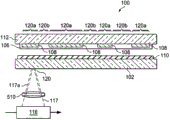
As shown in Figure 1A and 1B, encapsulate 100 basic composition by its top view and the visible seal glass of the present invention of sectional view.Described seal glass encapsulation 100 comprises the first glass plate 102, liquid 104, one or more assembly-electrodes 106 and 108 (optionally), frit 110 and the second glass plate 112.Described seal glass encapsulation 100 have the sealing 114 that formed by frit 110 (as; seal 114), contain liquid 104 and protect one or more assemblies 106 (if there is) that are positioned between the first glass plate 102 and the second glass plate 112.Electrode 108 (if there is) are connected with assembly 106, and penetrate sealing 114 to be connected (not shown) with external device (ED).Sealing 114 is usually located at glass-encapsulated 100 peripheries, makes liquid 104, assembly 106 (if there is) and at least a portion electrode 108 (if there is) be positioned at the circumference of sealing 114.How form sealing 114 by melt frit 110, and accessory part, as form for heating and melting frit 110 sealing 114 packoff 116 (as, laser instrument 116 or infrared lamp 116) do more detailed description by figure below 2-5.
As shown in Figure 2, with the step of the flowchart text method 200 of preparing seal glass encapsulation 100 of the present invention.Started by step 202 and 204, provide the first glass plate 102 and the second glass plate 112 to prepare seal glass encapsulation 100.In one embodiment, described the first and second glass plates 102 and 112 are transparency glass plates, for example soda-lime glass plate or brand password 1737 glass (Code 1737 glass) by name or hawk board 2000 by Corning Incorporated's production and selling
tMglass (Eagle 2000
tMglass) glass plate.Or, described the first and second glass plates 102 and 112 can be transparency glass plates, for example by Asahi Glass company (Asahi Glass Co.) (as, OA10 glass and OA21 glass), the transparency glass plate of Gao electric glass company (Nippon Electric Glass Co.), NHTechno company and the meticulous glass company of SCP (Samsung Corning Precision Glass Co.) production and selling.If needed, glass plate 102 and 112 can have one or be all opaque.In addition, the thermal expansivity (CTE) of glass plate 102 and 112 can be at scope 32-90x10
-7/ DEG C, thereby in display application, can adopt compared with expensive low CTE glass and in solar cell application, adopt more cheap high CTE glass.
In step 206, along the marginal deposit frit 110 of the first glass plate 102, make frit 110 form a closed hoop on the first glass plate 102 surfaces.For example, frit 106 can be placed on apart from the place of the first glass plate 102 free about 1mm in limit.In one embodiment, frit 110 is a kind of low temperature glass frit, the absorbability ion (as transition metal) that contains one or more chosen from Fe, copper, vanadium and neodymium.Described frit 110 also can doped with the thermal expansivity (CTE) that can reduce frit 110 make it mate with the CTE of glass plate 102 and 112 or the filler of basic coupling (as, reverse filler or interpolation property filler).But the CTE of frit 110 need not mate with the CTE of glass plate 102 and 112, because we test, can adopt CTE is 35-40x10
-7/ DEG C frit 110 to seal CTE be 90x10
-7/ DEG C soda-lime glass plate 102 and 112.In one embodiment, the CTE of frit 110 can be less than 40x10
-7/ DEG C, and CTE scope in the first glass plate 102 and the second glass plate 112 can be 32-90x10
-7/ DEG C.The composition of the exemplary frit 110 of the number of different types that can adopt describes in detail in following table 1-4.
In step 208 (optionally), frit 110 can be pre-sintered on the first glass plate 102.In order to realize this purpose, need to make it be adhered to the first glass plate 102 frit 110 heating that are deposited on the first glass plate 102.For example, this presintering step 208 can heat 1 hour by the frit 110 of the first glass plate 102 and deposition being put into inherent 400 DEG C of heating furnace, thereby then prevents that so that control rate is cooling frit 110 and the first glass plate 102 from having ftractureed.If need, can grind this presintering frit 110 and make its variation in thickness be less than 5-10 μ m (for instance).
In step 210, liquid 104 is deposited in the space being limited by the inner side 118a of frit 110 and the surface of the first glass plate 102.In one embodiment, described liquid 104 at least contacts with the inner side 118a of frit 110.In another embodiment, liquid 104 all contacts with outside 118b with the inner side 118a of the frit 110 on the first glass plate 102.In this case, this first glass plate 102 and frit 110 are dipped in liquid 104 at least partly.
In step 212 (optionally), assembly 106 (as OLED106) is placed on the second glass plate 112 with the electrode 108 that is connected.If while adopting encapsulating method of the present invention to prepare the glass-encapsulated 100 of receiving fluids 104 only, this step can be omitted.
In step 214, described the second glass plate 112 is placed in the top of the frit 110 on the first glass plate 102, thereby liquid 104 can be stayed in the space being limited by the inner side 118a of frit 110 and the surface of the first glass plate 102.If needed, described the second glass plate 112 can be placed in the top of the frit 110 on the first glass plate 102, thereby the liquid 104 that makes assembly-electrode 106 and 108 (if there is) also may contact its outside 118b with the inner side 118a that directly contacts frit 110 contacts.
In step 216, frit 110 by packoff 116 (as, laser instrument 116, infrared lamp 116) heating, this type of heating can make frit 110 form to connect the sealing 114 (as, seal 114) (seeing Figure 1B) of the first glass plates 102 and the second glass plate 112.Sealing 114 liquid 104 that also held between the first glass plate 102 and the second glass plate 112.In addition, sealing 114 can be by stoping, and for example, the oxygen G&W in surrounding environment enters seal glass encapsulation 100 and protects assembly 106 (if there is).
If needed, described packoff 116 can be used for emission of light 117 (laser beam 117) and heats frit 110, its mode is to make light 117 along the frit 110 that has electrodeless region 108 and have an electrode zone 108 (if employing) (for example, along potted line 120) mobile, the temperature of frit is elevated to a substantially invariable temperature until frit 110 melts and form the sealing 114 of connection the first glass plate 102 and the second glass plate 112.Carry out more at large to describe described constant temperature Sealing Technology by providing about some exemplary glass encapsulation 100 and some discussion that can be used for the exemplary frit 110 of preparing this glass-encapsulated 100 herein.
exemplary dye solar cell 100
As shown in Figure 3, be to have summarized the chart how according to the present invention encapsulating method 200 prepares the method for dye solar cell 100.First, provide the glass plate (label that sees reference " 1 ") that scribbles indium tin oxide target (ITO).In one embodiment, described glass plate 102 can be transparency glass plate, is called password 1737 glass (Code 1737 glass) or hawk board 2000 as soda-lime glass plate or by the brand of Corning Incorporated's produce and market
tMglass (Eagle 2000
tMglass) glass plate.Along glass plate 102 marginal deposits, make frit 110 form closed hoop on glass plate 102 frit 110 (frit thickener 110).For example, frit 110 can have following composition: Sb
2o
3(7.4 molar percentage), ZnO (17.6 molar percentage), P
2o
5(26.5 molar percentage), V
2o
5(46.6 molar percentage), TiO
2(1.0 molar percentage) and Al
2o
3the beta-eucryptite glass-ceramic CTE reduction type filler that (1.0 molar percentage) and at least 30% particle mean size are less than 3 microns.Afterwards, frit 110 can be pre-sintered on glass plate 102.For example, can be by the frit 110 of glass plate 102 and deposition being put into the inherent 400 DEG C of heating of heating furnace 1 hour, then under control rate cooling come presintering frit 110 make it be adhered to glass plate 102.
Second step, deposits to conducting liquid 104 (label that sees reference " 2 ") in the space being limited by the inner side 118a of frit 110 and the surface of glass plate 102.As shown in the figure, this conducting liquid 104 contacts with the inner side 118a of frit 110.Or liquid 104 can contact with outside 118b with the inner side 118a of the frit 110 on glass plate 102 simultaneously.In this case, the first glass plate 102 and frit 110 are dipped in liquid 104 at least partly.
The 3rd step, provides one to scribble indium tin oxide target (ITO) or any other conductive coating as the glass plate 112 of FTO tin oxide iron (label that sees reference " 3 ").In one embodiment, glass plate 112 can be transparency glass plate, as soda-lime glass plate or the brand manufactured by Corning Incorporated password 1737 glass (Code 1737) by name or hawk board 2000
tMglass (Eagle 2000
tMglass) glass plate.Then, thickener 124 (as, titanium thickener 124) is applied on the surface of glass plate 112.By glass plate 112 and thickener 124 sintering that apply, make thickener 124 be adhered to glass plate 112.
The 4th step, can add colorant 126 (as, ruthenium) to be arranged in the sintering on glass plate 112 thickener 124 (label that sees reference " 4 ").The sequence of steps associated with reference number 1-2 and 3-4 is unimportant because after the step that the step being associated with reference number 3-4 can be associated at reference number 1-2, before or carry out simultaneously.
The 5th step, is placed in glass plate 112 top of glass plate 102 upper glass material 110, receiving fluids 104 and there is no bubble only in the space that makes to be limited by the inner side 118a of frit 110.Then, packoff 116 (as laser instrument 116, infrared lamp 116) transmitting light beam 117 heats frit 110 and forms the sealing 114 (as seal 114) that connects two glass plates 102 and 112.As shown in the figure, described packoff 116 is positioned at the second glass plate 112 tops, makes light beam 117 carry out heating and melting frit 110 by the second glass plate 112, thus bonding two glass plates 102 and 112.Or described packoff 116 can be positioned at the first glass plate 102 belows, make light beam 117 carry out heating and melting frit 110 by the first glass plate 102, thus bonding two glass plates 102 and 112.
About the more detailed discussion of some basic compositions and the characteristic of conventional dyes solar cell, please participate in following list of references:
1.Bernard Wenger etc. " exceeds the speed limit photoinduced from ruthenium (II) compound emulsion to receiving crystal TiO
2the ultimate principle of power unevenness that shifts of electronics " (Rationale for Kinetic Heterogeneity of Ultrafast Light-Induced Electron Transfer from Ru (II) Complex Sensitizers to Nanocrystalline TiO
2), the photonics of the chemical engineering institute of Lausanne ecole polytechnique research institute and laboratory, interface (Laboratory for Photonics and Interfaces, Institute of Chemical Sciences and Engineering, Ecole Polytechnique Fe ' de ' rale de Lausanne), Lausanne, SUI on Dec 31st, 1015,2004 (revision on July 23rd, 2005).
2. Michael removes from office orchid and hereby " derives from generating electricity and producing the medium-sized solar cell of hydrogen of daylight " (Mesoscopic Solar Cells for Electricity and Hydrogen Production from Sunlight), Chemical Letters, the 1st section of 34 volume (2005).
3.R.Sastrawan etc. " have glass frit-sealing dye solar cell module of complete series connection " (Glass Frit-Sealed Dye Solar Cell Module with Integrated Series Connections), solar energy materials and solar cell, the 90th volume, o. 11th, 1680-1691 page, on July 6th, 2006.
4. the Application No. 2006/0160265A1 of " preparing the method for photo-electric conversion element " (Method of Manufacturing Photoelectric Conversion Element) by name.
The content of these documents is included in herein by reference.
Can know that by reading these documents seal glass encapsulation 100 of the present invention and encapsulating method have multiple advantages with respect to prior art.Below enumerate some advantages wherein:
Thereby greatly reduce the cost that has reduced seal glass encapsulation 100 for the preparation of the preparation process quantity of seal glass encapsulation 100.Specifically, no longer need to after two seal glass plate spacing filling liquids, seal described hole in the one or more holes by glass plate.
Utilize frit 110 can reduce the repeatability that thereby the tolerance limit of material 106 thickness in glass-encapsulated 100 is strengthened to seal glass encapsulation 100.
Adopt the method for package sealing with laser frit can accelerate the preparation speed of seal glass encapsulation 100.
The glass-encapsulated 100 that sealing includes liquid 104 just no longer needs special injection device and seal glass encapsulation 100 is done to expensive inspection.And then obtain higher output and lower cost.
experimental glass-encapsulated 100
We have carried out multinomial experiment liquid 104 have been sealed in glass-encapsulated 100 (can be dye solar cell 100, electric wet-type display 100, OLED display 100 etc.) according to the present invention.These experiments and result thereof, as shown in Fig. 4 A-4G, will further be discussed hereinafter.
As shown in Figure 4 A, illustrated for different experiments to detect the experimental frit glass plate 102 of the sealing of glass-encapsulated 100 to liquid 104 and the size of frit 110.In the present embodiment, the high 50 μ m of frit 110, diameter 1mm.Brand password 1737 glass by name or the hawk board 2000 that comprise soda-lime glass plate and manufactured by Corning Incorporated for the glass plate 102 of these experiments
tMthe glass plate of glass.
As shown in Figure 4 A, frit 110 is for having the square closed hoop of four fillets 111 (radius is 1mm), and it is used to different experiments and determines the scope that seals two glass plates 102 according to the present invention and can succeed enforcement at 112 o'clock.But in many these experiments, the height of frit 110, thickness, width, diameter and concrete composition are all different.Encapsulating method in many these experiments is all implemented as soon as possible, to avoid liquid 104 to seethe with excitement in seal glass plate 102 and 112.
Fig. 4 B is the photo of seal glass encapsulation 110, is wherein equipped with and adopts laser instrument 116 successfully to seal coefficients match type liquid 104 therein according to the present invention.So-called coefficients match, refer to that the refractive index of selected liquid 104 mates substantially with the refractive index of the second glass substrate 112, thereby it is minimum that internal reflection degree is dropped to, and makes the light output quantity of (for example) top transmitting OLED device reach maximum.In fact, in these experiments, successfully prepare the multiple different seal glass encapsulation 100 that coefficients match oil, impregnating oil, electrolyte iodine solution (having the platinum electrode 108 that extends frit 110), distilled water or ethylene glycol-water mixture (ethylene glycol content is 20%-50%) are housed.
With regard to light-output, more complicated.In OLED equipment, the refractive index of ITO layer, organic layer and glass is approximately respectively 2.0,1.7 and 1.5.According to estimates, the light of generation approaches 60% and is trapped through internal reflection in ITO/ organic EL, and 20% is trapped in glass substrate, in fact only has an appointment 20% can send and play beneficial effect by equipment in the light of generation.Most of light is trapped within ITO, and can not contact with gap dielectric.Gap is filled up to the reflection that can reduce in OLED/ air and glass cover/air interface.As shown in Figure 4 C, be to derive according to these figure that improvement value is done, x axle represents " medium coefficient ", y axle represents " light-output improvement value ".
While deriving 20%, the highest improvement that obtains about 10-11%, is approximately 2% of total intensity generally.But it is exactly remarkable reaching comparatively speaking 10% improvement.For example, the refractive index of supposing OLED equipment is 1.7, the refractive index of healthy and free from worry hawk board glass is 1.55, so as shown in Figure 4 D, by Newton ring (NR) contrast to the mapping of the gap dielectric liquid 104 of gap (as be full of) refractive index, wherein x axle represents " refractive index of medium ", and y axle represents " NR contrast ".As shown in the figure, the refractive index of gap dielectric or liquid 104 is increased at 1.45 o'clock, the observability of Newton ring can be reduced to 2 orders of magnitude.The ranges of indices of refraction of liquid 104 is 1.3-1.9.Liquid 104 can have almost any viscosity.For example, can adopt and there is relatively full-bodied liquid 104, as corn syrup, and there is relatively low viscous liquid 104, as acetone.The selection of liquid 104 to make it can and plate 102 and 112 between the other materials of sealing compatible with each element.If need, can form protective seam to protect them to avoid the interference of coefficients match liquid 104 on the other materials of sealing between plate 102 and 112 and element.
Consider above these; should understand described encapsulating method 200 can be used for the liquid 104 in filling glass substrate 102 and 112 gaps to be sealed in OLED display; thereby provide support for glass substrate 102 and 112; and reduce insoluble Newton ring, also avoid insoluble the sinking and contact problems often there will be in large scale on-liquid filled-type OLED display.Specifically, make to seal the effectively substantially bubble-free sealing 114 of generation of step thereby described encapsulating method 200 has certain cumulative volume by the bubble in guarantee liquid 104, can reduce Newton ring and avoid sagging.In practice, in liquid 104, can have bubble but their volume should be less than owing to being applied to external pressure on glass substrate and changes the gap that causes between the glass substrate 102 and 112 that glass substrate 102 and/or 112 sink or deflection causes and in frit or the volume-variation in space, described external pressure change can be external environment condition pressure change or with object as due to the finger applying pressure on a glass substrate contacts.
In all these experiments, described method is all that deposit liquid 104 makes its submergence frit 110, has week that some liquid 104 can stay frit 110 in seal process out-of-bounds.Adopt laser instrument 116 to heat frit 110 and liquid 104, seal liquid 104 114 time and be extruded between frit 110 and the second glass substrate 112 when frit 110 melts and forms.Sealing hawk board 2000
tM glass plate 102 and 112 and frit 110 width while being about 0.7 millimeter, laser instrument 116 has the sealing speed of 20 mm/second and the spot size of 1.8 millimeters.It is 37-40 watt that liquid 104 is sealed into required power between these glass plates 102 and 112, required 33 Wa Lvegao when no liquid seal glass plate in the middle of comparing.But, when wide 0.7 or 1.0 millimeter of sealing soda- lime glass plate 102 and 112 and frit 110, laser instrument 116 operates within the scope of 38-42 watt, its sealing speed is about 2 mm/second, and beam sizes is greater than 3.5 millimeters (notes: these specific air-proof conditions are also applicable to subsequent experimental as described below).Front or rear by glass plate 102 upper glass material 110 import laser beam 117, thereby carry out described sealing.Under all situations, all can produce liquid 104 " thermal " when laser instrument 116 seals, their can move together with laser beam 117, " unnecessary bubble " can be in frit 110 circumferences to escape, until sealing 114 rings are closed.Now, the glass-encapsulated 110 of sealing only has very small bubble to be trapped in the interior circumference of frit 110.
The seal glass encapsulation 100 vanadium frits 110 that comprise the β eucryptite glass-ceramic CTE reduction type filler with different content of test, find, CTE reduction type filer content must not obtain sealing 114 lower than 30% time, has at least frit 110 of 30%CTE reduction type filler and can obtain sealing 114.Trace it to its cause, we think because the CTE reduction type filler of high level can strengthen the liquid vapour infiltration frit 110 producing in liquid 104 and seal process and steam frit 110 and glass plate 112 between the ability at interface.On the contrary, the CTE reduction type filler of the lower content in frit 110 can make liquid 104 and liquid vapour be stranded the interface between frit 110 and glass plate 112, and this seals two glass plates 102 exactly and 112 o'clock institutes are unwanted.In these experiments, we are clear and definite is that the boiling point of liquid 104 does not play a crucial role in this seal process, and when the seal temperature of frit 110 is during higher than 600 DEG C, we can successfully be sealed into the water with 100 DEG C of boiling points.
Prepared seal glass encapsulation 100 out in these experiments is placed about 1 month or on hot plate, placed about 1 hour under vacuum environment, and they have all successfully passed through sealing test result.Seal glass encapsulation 100 is placed on hot plate and processes and within 1 hour, do not destroy sealing 114 with 95 DEG C of high temperature, and still, " minute bubbles " that at room temperature can observe in glass-encapsulated 100 occur to expand very significantly.This expansion is reversible, because hermetically sealed 100 cooling getting back to after room temperature, bubble diminishes again.
As shown in Figure 4 E, this figure exposes the photo of rear the seen glass plate 402a of basic unit (glass plate 102) of the frit 110 bonding on two glass plates 102 and 112 and 3 frit cover plate 402b, 402c and 402d (glass plate 112) for tearing seal glass encapsulation 100.In this experiment, if liquid 104 has disturbed the sealing ability of cover plate 112,, after substrate 102 is opened, they can not comprise frit 110.Observe these photos, the bonding that can find out frit 110 and two glass plates 102 and 112 is better than the bonding of frit 110 self.This point is from pulling open glass-encapsulated 100, glass plate 102 with 112 with frit 110 between bonding keep complete and frit 110 to find from separating in the middle of self.In this experiment, the glass-encapsulated 100 that is sealed with liquid 104 (electrolyte 104) before package sealing with laser process, during with all directly contact with 118b with frit 110 both sides 118a afterwards.
As shown in Fig. 4 F, this figure is the photo of the seal glass that comprises iodine electrolyte (idiolyte) 104 (for the photronic liquid electrolyte) encapsulation 100 of the sealing according to the present invention.Separately having a photo is the 5x top view that sees through the sealing 114 that one of glass plate 102 and 112 of glass-encapsulated 100 sees.In this experiment, in package sealing with laser process, iodine electrolyte 104 is positioned on the inner periphery 118a and outer circumferential 118b of frit 110.Fig. 4 G is the side view of seal glass encapsulation 100.
experimental frit 110
In one embodiment, frit 110 is by making doped with the glass of one or more transition metals (as vanadium, iron and/or neodymium), to strengthen its absorption characteristic (seeing Figure 1A-1B) on the specific wavelength (as 800 nano wave lengths) of the light 117 (laser beam 117) by water-tight equipment 116 (laser instrument 116) transmitting.The enhancing of these frit 110 absorption characteristics means in the time that utilizing emitted light 117 is absorbed by frit 110, and frit 110 softens and form sealing 114 (seal 114).On the contrary, should make them not absorb or at least not absorb the irradiation that much carrys out self-seal device 116 selection of glass plate 102 and 112 (as, password 1737 glass plates 102 and 112).Therefore, glass plate 102 have on the specific wavelength of light 117 with 112 relative low absorption can contribute to make the sealing 114 (seal) that forms to the undesirable heat of liquid 104 and assembly electrode 106 and 108 (if there is) shift drop to minimum.
The selection of the transition metal in frit 110 and concentration depend on particular type, the power of light 117 and the point-to-point speed of light 117 of packoff 116.Specifically, the packoff 116 adopting should produce as the light wavelength lambda in the high absorption bands of particular glass material 110.For example, all kinds of packoffs 116 that can be used in this seal process comprise semiconductor laser 116 (λ=800-980 nanometer), titanium: sapphire persistent wave (CW) laser instrument 116 (λ=810 nanometer), ytterbium persistent wave (CW) laser instrument 116 (900 nanometer < λ < 1200 nanometers), neodymium: yttrium aluminum garnet (Nd:YAG) persistent wave (CW) laser instrument 116 (λ=1064 nanometer), neodymium: (m) (λ ≈ 1.5 μ m) with erbium persistent wave (CW) laser instrument 116 for λ=1.08 μ for YALO persistent wave (CW) laser instrument 116.
Shown in the table 1-4 composed as follows of the exemplary frit 110 of number of different types, all at the corotation of by name " by glass-encapsulated of frit-sealed encapsulation and preparation method thereof " by United States Patent (USP) 6,998, launched detailed description in 77.Document content is included in herein by reference.
table 1

Note 1: CTE reduction type filler defined above, as lithium aluminosilicate, is a kind of " interpolation property filler ".Or frit 110 can use another kind of CTE reduction type filler, as pyrophosphoric acid cobalt-magnesium, it is a kind of " reverse filler ", can make frit 110 produce change in size by phase transformation in heating or when cooling.
Can be used for multiple other exemplary frits 110 of the present invention as shown in table 2.These exemplary frits 110 are owing to having low T
g(being 350 DEG C of <) and low seal temperature (550 DEG C of <) and more welcome.
table 2

The present invention can also adopt another kind of exemplary frit 110, and phosphoric acid almagrerite frit 110 is (as, the 20ZnO-30P of mole base
2o
5-50V
2o
5).If need described phosphoric acid almagrerite frit (mole base: 20ZnO-30P
2o
5-50V
2o
5) can comprise CTE reduction type filler, i.e. beta-eucryptite glass-ceramic (mole base: 25Li
2o-25Al
2o
3-50SiO
2), (weight base) as follows:
Frit, (particle mean size 5-10 μ m) 75%
Filler (particle mean size 5-10 μ m) 10%
Filler (particle mean size 15-20 μ m) 15%
The present invention also can adopt another kind of exemplary vanadium frit 110, and as shown in Tables 3 and 4, all elements all represents with molar percentage:
table 3
| Vanadium frit 110 | |
| K 2O | 0-10 |
| Fe 2O 3 | 0-20 |
| Sb 2O 3 | 0-20 |
| ZnO | 0-20 |
| P 2O 5 | 20-40 |
| V 2O 5 | 30-60 |
| TiO 2 | 0-20 |
| Al 2O 3 | 0-5 |
| B 2O 3 | 0-5 |
| WO 3 | 0-5 |
| Bi 2O 3 | 0-5 |
Table 4 has been listed the composition of the another kind of vanadium frit 110 adopting in the above-mentioned experiment about dye solar cell 100 and other glass-encapsulated 100, and this vanadium frit 110 preferably contains at least 30% beta-eucryptite glass-ceramic interpolation property filler.The particle mean size that forms two kinds of components of this specific vanadium frit 110 is 3 microns.
table 4
| |
|
| Sb 2O 3 | 7.4 |
| ZnO | 17.6 |
| P 2O 5 | 26.5 |
| V 2O 5 | 46.6 |
| TiO 2 | 1.0 |
| Al 2O 3 | 1.0 |
The above-mentioned frit composition of listing in table 1-4, should be appreciated that, also have other frit compositions also to can be used for sealing two glass plates 102 and 112.For example, in the common United States Patent (USP) 7,407,423 of transferring the possession of and Application No.: 2006-0009109 and 2007-0007894, disclosed frit 110 also can be used for sealing two glass plates 102 and 112.The content of these documents is included in herein by reference.
exemplary Sealing Technology (step 216)
Described Sealing Technology can comprise following basic step:
1. vacuum grease pearl is put on from the plate edge of at least 10 millimeters of distant places of frit;
2. on the sintering cover plate in frit boundary, distribute oil;
3. rear plate is placed in to the top of sintering cover plate, makes one spring song, drive as far as possible residual bubble away thereby oil can be flowed;
4. pair vacuum grease pearl is exerted pressure two boards " sealing " is arrived together;
5. this subassembly being placed in to vacuum tightness is 1-10x10
-3between vacuum chamber in air was overflowed in 2 to 5 minutes, oil immersion goes out frit boundary;
6. carry out laser instrument sealing according to frit kind and the definite standard conditions of width.
If needed, utilize packoff 116 to heat frit 110, so that along with packoff moves the temperature of frit is brought up to basic constant temperature along the potted line 120 of frit 110, frit 110 is melted and form the sealing 114 (as seal 114) that connects the first glass plate 102 and the second glass plate 112, on sealing line, some region is electrodeless 108, and some region has the electrode 108 (if employing) being connected with assembly 110 (if employing).This can realize by the Sealing Technology that adopts disclosure and description in the common United States Patent (USP) sequence number 10/970,319 that is called " being sealed with the parameter optimization of OLED (OLED) display " of transferring the possession of.Document content is included in herein by reference.
Described in some following Fig. 5 A-5G in these encapsulating methods (note: cannot see liquid 104 for the concrete diagram of explaining some different exemplary Sealing Technologies).Following Sealing Technology make packoff 116 can along with in seal process along frit 110 potted lines 120 move and rising frit temperature to basic constant temperature, thereby and consideration can have influence on rate of heat transfer and affect the many factors of the temperature of the seal point 120 of frit 110.First, sealing technology considers that typical glass material 110 is different with thickness because of its composition, and conduction/light absorbing ability has the variation of 2%-30%.Secondly, sealing technology also considers that electrode 108 may have different patterns, may partially absorb or part reflected light 117 according to composition difference.The 3rd, sealing technology considers that the heat conductivility of the first and second glass plates 102 and 112 in the time existing or do not have depositing electrode 108 can have influence on the rate of heat transfer of seal point 120.Can ensure that packoff 116 is equably along comprising electrodeless region 120a and having the potted line 120 of electrode zone 120b to heat frit 110 to described in the following Fig. 5 A-5G of different sealing technology of required seal temperature.
As shown in Figure 5A, this figure is the sectional view of the glass-encapsulated 100 of a kind of Sealing Technology sealing (as seal) wherein according to the present invention.In this embodiment, sealing technology is to need laser instrument 116 on the difference of potted line 120, dynamically to change the power of laser beam 117, so that frit 110 maintains substantially invariable temperature along including on the potted line 120 of electrode zone 120a and electrodeless region 120b.For example, in the time having electrode 108 region 120a to appear on potted line 116, reduce laser beam 117 power, and in the time that electrodeless region 218b appears on potted line 116, increase laser beam 118 power, thereby when laser instrument 116 is moved along potted line 120, frit 110 is heated to constant peak temperature.
As shown in Figure 5 B, this figure is with the diagram of helping describe second Sealing Technology of sealing (as seal) glass-encapsulated 100 according to the present invention.In this embodiment, the Sealing Technology adopting is in the time that laser beam moves along the potted line 120 that includes electrode 108 region 120a and electrodeless region 120b, and the speed (v) that laser instrument 116 dynamically changes laser beam 117 heats frit to substantially invariable temperature.For example, laser instrument 116 can be by making laser beam 117 move hurry up when having electrode zone 120a, slow movably during by electrodeless region 120b, and make frit 110 keep stationary temperature on potted line 120.If need, can make near the region that have electrode 108 of laser instrument 116 potted line 120 move laser beam 117 with the 3rd medium speed.When no matter electrode 108 is high absorption and/or high reflection, all can adopt the method.Or, not mobile laser instrument 116 above static glass-encapsulated 100, but below static laser instrument 116 with platform/support (not shown) of different rates movable support glass-encapsulated 100, thereby in frit 110, maintain stationary temperature (note: this concrete setting can be used for any Sealing Technology as herein described).
As shown in Figure 5 C, this figure is according to the sectional view of the glass-encapsulated 100 of another kind of Sealing Technology sealing of the present invention (as seal).In this embodiment, Sealing Technology is that high reflecting body 502 (as, minute surface 502) is placed on the second glass plate 112, makes laser instrument 116 Emission Lasers bundle 117 melt frit 110 and forms sealing 114 (seal 114).The power that described high reflecting body 502 contributes to balance frit 110 to absorb, and no matter frit 110 is positioned at has under electrode district 120a or electrodeless district 120b.For example, raise and can be expressed as along the temperature of the frit 110 of difference on potted line 120:
There are being electrode 108 region 120a:
T (frit) 1=P/a
2be multiplied by (vD) (square root of ε (frit)+(1-ε (frit) e (electrode)+(1 ε frit) R (electrode) ε (frit))
With, at electrodeless region 120b:
T (frit) 2=P/a
2be multiplied by the square root of (vD) (ε (frit)+(1-ε (frit)) * R (reflecting body) * ε (frit))
Wherein T (frit) is the temperature rising of frit 110, P is the laser power of laser instrument 116, v is laser point-to-point speed, a is laser facula size, D is the temperature conductivity of the second glass plate 112, ε (frit) is the number percent of the laser power that absorbs of the first path upper glass material 110, and R (electrode) is that the reflectivity of electrode 108 and e (electrode) are the number percent of the laser power that absorbs of electrode 108.As shown in the figure, can adopt high reflecting body 502 to reduce the difference of T (frit) 1-T (frit) 2.This difference depends on optical parametric and the attribute of electrode 108.Should be realized that, in this Sealing Technology, the power of described laser beam 117 and/or speed can keep constant or dynamically change.
As shown in Figure 5 D, this figure is according to the sectional view of the glass-encapsulated 100 of another kind of Sealing Technology sealing of the present invention (as seal).In this embodiment, described Sealing Technology is that the mask 504 of part reflection is placed on the first glass plate 102, and laser instrument 116 Emission Lasers bundles 117 melt and form sealing 114 (seal 114).The mask 504 of this part reflection has different pattern 506a, 506b...506d, represents respectively the different reflectivity of mask 504, with the different attribute of compensating electrode 108.Like this, the power that the mask 504 of this part reflection can help balance frit 110 to absorb, no matter and frit 110 is positioned at and has electrode district 120a or electrodeless district 120b.
As shown in Fig. 5 E, this figure is according to the sectional view of the glass-encapsulated 100 of another kind of Sealing Technology sealing of the present invention (as seal).In this embodiment, sealing technology is that while making laser instrument 116 first pass, the lowest power with the correct seal temperature corresponding to along potted line 120 seals at least a portion frit along potted line 120, and the position that does not then reach correct temperature in the time of second time when more high power is only for first pass completes the sealing of potted line 120.Can adopt and measure frit 110 with following same or similar feedback mechanism 508 and have which position not reach correct temperature when the first pass.
As shown in Fig. 5 F, this figure is according to the sectional view of the glass-encapsulated 100 of another kind of Sealing Technology sealing of the present invention (as seal).In this embodiment, sealing technology is to adopt feedback mechanism 508 to help ensure that frit 110 inside obtain homogeneous heating along potted line 120 in the process that forms sealing 114 (as seal 114).This feedback mechanism 508 can be used for monitoring the intensity of hot spots of a certain fixed wave length lower seal line 120.When being derived from laser instrument 116 and heating, focus raises and the black matrix transmitting that causes along potted line 120 temperature.Its emission spectrum is very wide, and the almost any wavelength between 500-2000 nanometer all can be used for this object.In one embodiment, feedback mechanism 508 is monitored instant emissive porwer, convert it to temperature, and optimize one or more seal parameters (as, the power of laser beam 117 and speed) though with ensure the peak temperature improving be frit 110 to have on electrode district 120a or the potted line 120 of electrodeless district 120b be all homogeneous.For example, though this feedback mechanism 508 can be used for helping controlling the power of laser instrument 116 make temperature frit 110 to have on electrode district 120a or the potted line 120 of electrodeless district 120b be all homogeneous.In fact, there are many diverse ways to use this feedback mechanism 508, introduce certain methods wherein below:
In the time that laser instrument 116 seals a unknown sample glass-encapsulated 100, this feedback mechanism 508 can be monitored the temperature of potted line 120 diverse locations.Feedback mechanism 508 can change along laser speed or the power in potted line 120 somewheres, and when ensureing sealed sample glass-encapsulated 100, frit 110 internal temperatures are constant.Then, laser instrument 116 can use these conditions to seal similar glass-encapsulated 100.
In the time that laser instrument 116 seal glass encapsulate 100, feedback mechanism 508 can be monitored " on one's own initiative " temperature of diverse location on potted line 120.Feedback mechanism 508 also changes along the laser speed in potted line 120 somewheres or power and encapsulates at 100 o'clock to ensure seal glass, and the peak temperature of raising is constant along frit 110.
As shown in Fig. 5 G, this figure is according to the sectional view of the glass-encapsulated 100 of another Sealing Technology sealing (as seal) of the present invention.In this embodiment, sealing technology is the beam shape that the circular hole 510 (or hole 510 of other special shapes) by being positioned at laser instrument 116 ends changes laser beam 117.By hiding/scatter size that a part for light beam 117 changes described circular hole 510 to adjust laser beam 117, thereby make the laser beam 117a through adjusting heat frit 110 along the potted line 120 of glass-encapsulated 100.Substantially, circular hole 510 or lens go the tail of the laser beam 117 of transmitting to adjust the gaussian shape of laser beam 117 by sanction.The laser beam 117a defocusing also has the 1/e power level of reduction, and can be potted line 120 provides required covering and required power and can not make any assembly 106 (if there is) of glass stockline 120 inside be exposed to the heating that likely permanently destroys glass-encapsulated 100 simultaneously.In another embodiment, can have the ring of covering (not shown) in the middle of described circular hole 510, make laser beam 117 ovalizes, this contributes to make temperature homogeneous on frit 110, and can as normal conditions, more easily not dispel the heat at edge.Described oval-shaped laser beam 117 can not only make frit 110 homogeneous heatings, and can ensure to carry out progressively heating and cooling along frit 110, thereby contributes to reduce unrelieved stress.
Should be appreciated that, the sealing 114 that can simultaneously adopt more than one methods in above-mentioned encapsulating method to carry out melt frit 110 to form adhesive glass encapsulation 100 (as, seal 114).The method (seeing Fig. 5 G) that for example, can adopt the encapsulating method (seeing Fig. 5 A) of above-mentioned change laser instrument 116 power and adopt circular hole 510 to change laser beam 117 shapes seals described glass-encapsulated 100.In addition, laser instrument 116 can penetrate the second glass plate 112 by Emission Lasers bundle 117, instead of penetrates the first glass plate 102 and heat frit 110.
Although many embodiments of the present invention have been described with reference to accompanying drawing and detailed Description Of The Invention above, it should be understood that, the invention is not restricted to disclosed these embodiments, under the prerequisite that does not depart from the present invention's design being limited by appended claims, can carry out various rearrangements, amendment and replacement.
Claims (7)
1. a method for seal glass encapsulation, said method comprising the steps of:
The first glass plate is provided;
The second glass plate is provided;
Frit is deposited on the first glass plate, makes described frit form closed hoop on the first glass plate, wherein, described frit has at least 30% thermal expansivity (CTE) reduction type filler;
Described frit is pre-sintered on described the first glass plate;
By liquid deposition, in the space being limited by described presintering frit inner side and the first glass pane surface, this liquid at least directly contacts with at least a portion outside inner side and the described frit of described frit one;
The second glass plate is placed in to the frit top on the first glass plate, liquid is stayed in the space being limited by the frit inner side on the first glass plate; With
Adopt packoff, frit as laser instrument heating described, melts described frit and forms the sealing of connection the first glass plate and the second glass plate, and between the first glass plate and the second glass plate receiving fluids; Described liquid in described frit inner side contains bubble, and its cumulative volume is less than by the spatial volume due to glass plate deflection in external environment condition pressure change procedure and changes.
2. the method for claim 1, is characterized in that, described frit:
Doped with at least one transition metal, described at least one transition metal is the absorbing agent for the special wavelength light of described packoff transmitting; And/or
The CTE reduction type filler that contains scheduled volume, in the time using described packoff to heat the sealing of described frit formation connection the first glass plate and the second glass plate, this CTE reduction type filler can make Liquid Penetrant arrive in described frit, and evaporates away via the interface between described frit and the second glass plate.
3. the method for claim 1, it is characterized in that, adopt the operation of feedback mechanism optimization to described packoff, to comprised electrodeless region and had the potted line heating frit of electrode zone to keep the substantially invariable mode of frit temperature to melt described frit by edge, described electrode is connected by least one component in described glass-encapsulated.
4. method as claimed in claim 3, is characterized in that,
Dynamically change the power of described laser beam, so that along comprising electrodeless region and having the potted line of electrode zone that described frit is heated to substantially invariable temperature;
Dynamically change the speed of described laser beam, so that along comprising electrodeless region and having the potted line of electrode zone that described frit is heated to stationary temperature;
Reverberator is arranged on described the second glass plate, and described packoff gives off laser beam through described the first glass plate, along comprising electrodeless region and having the potted line of electrode zone that described frit is heated to substantially invariable temperature;
The mask of part reflection is arranged on described the first glass plate, and described packoff gives off laser beam through mask and described first glass plate of described part reflection, along comprising electrodeless region and having the potted line of electrode zone that described frit is heated to substantially invariable temperature;
Described packoff adopts the hole of given shape to send the laser beam defocusing, to comprised electrodeless region and had the potted line of electrode zone to keep the substantially invariable mode of frit temperature to melt described frit by edge; Or
In first pass, described packoff transmitting lower-wattage laser beam is along potted line melt frit, then, in second time, described packoff transmitting higher-wattage laser beam is only irradiated for the frit subregion along potted line that does not reach correct temperature under first pass lower-wattage laser beam irradiation.
5. the method for claim 1, is characterized in that, described glass-encapsulated is:
Solar cell;
Electric wet-type display; Or
Organic Light Emitting Diode OLED device.
6. the method for claim 1, is characterized in that, thermal expansivity (CTE) scope of described the first glass plate is 32-90x10
-7dEG C, the CTE of described frit is less than 40x10
-7dEG C.
7. a glass-encapsulated, it comprises:
The first glass plate; With
The second glass plate, wherein said the first glass plate and the second glass plate are each other via being connected at the frit that forms sealing between the first glass plate and the second glass plate; With
In the space limiting and described frit, comprise liquid between described the first glass plate and the second glass plate;
Described frit is the glass doped with the thermal expansivity of at least one transition metal and at least 30% (CTE) reduction type filler, in the time that described frit fusing forms the sealing that connects the first glass plate and the second glass plate, described CTE reduction type filler can make described Liquid Penetrant enter in described frit, and evaporates away from the interface between described frit and the second glass plate.
Applications Claiming Priority (3)
| Application Number | Priority Date | Filing Date | Title |
|---|---|---|---|
| US8400708P | 2008-07-28 | 2008-07-28 | |
| US61/084,007 | 2008-07-28 | ||
| PCT/US2009/004223 WO2010014161A1 (en) | 2008-07-28 | 2009-07-21 | Method for sealing a liquid within a glass package and the resulting glass package |
Publications (2)
| Publication Number | Publication Date |
|---|---|
| CN102138100A CN102138100A (en) | 2011-07-27 |
| CN102138100B true CN102138100B (en) | 2014-06-11 |
Family
ID=41610640
Family Applications (1)
| Application Number | Title | Priority Date | Filing Date |
|---|---|---|---|
| CN200980134683.7A Expired - Fee Related CN102138100B (en) | 2008-07-28 | 2009-07-21 | Method for sealing a liquid within a glass package and the resulting glass package |
Country Status (7)
| Country | Link |
|---|---|
| US (1) | US9165719B2 (en) |
| EP (1) | EP2321694A4 (en) |
| JP (1) | JP5357256B2 (en) |
| KR (2) | KR101588918B1 (en) |
| CN (1) | CN102138100B (en) |
| TW (1) | TWI403481B (en) |
| WO (1) | WO2010014161A1 (en) |
Families Citing this family (41)
| Publication number | Priority date | Publication date | Assignee | Title |
|---|---|---|---|---|
| JP5127465B2 (en) * | 2005-12-06 | 2013-01-23 | コーニング インコーポレイテッド | Sealed glass package and manufacturing method thereof |
| WO2009108319A1 (en) * | 2008-02-28 | 2009-09-03 | Corning Incorporated | Method of sealing a glass envelope |
| JP5308718B2 (en) | 2008-05-26 | 2013-10-09 | 浜松ホトニクス株式会社 | Glass welding method |
| JP5535652B2 (en) * | 2008-06-11 | 2014-07-02 | 浜松ホトニクス株式会社 | Glass welding method |
| JP5535653B2 (en) * | 2008-06-23 | 2014-07-02 | 浜松ホトニクス株式会社 | Glass welding method |
| US8245536B2 (en) * | 2008-11-24 | 2012-08-21 | Corning Incorporated | Laser assisted frit sealing of high CTE glasses and the resulting sealed glass package |
| KR101791580B1 (en) | 2009-10-17 | 2017-10-30 | 삼성전자주식회사 | An optical component, products including same, and methods for making same |
| JP5481167B2 (en) * | 2009-11-12 | 2014-04-23 | 浜松ホトニクス株式会社 | Glass welding method |
| JP5535589B2 (en) | 2009-11-25 | 2014-07-02 | 浜松ホトニクス株式会社 | Glass welding method and glass layer fixing method |
| JP5535590B2 (en) | 2009-11-25 | 2014-07-02 | 浜松ホトニクス株式会社 | Glass welding method and glass layer fixing method |
| JP5525246B2 (en) | 2009-11-25 | 2014-06-18 | 浜松ホトニクス株式会社 | Glass welding method and glass layer fixing method |
| JP5466929B2 (en) * | 2009-11-25 | 2014-04-09 | 浜松ホトニクス株式会社 | Glass welding method and glass layer fixing method |
| JP5535588B2 (en) | 2009-11-25 | 2014-07-02 | 浜松ホトニクス株式会社 | Glass welding method and glass layer fixing method |
| JP5481173B2 (en) | 2009-11-25 | 2014-04-23 | 浜松ホトニクス株式会社 | Glass welding method and glass layer fixing method |
| JP5567319B2 (en) | 2009-11-25 | 2014-08-06 | 浜松ホトニクス株式会社 | Glass welding method and glass layer fixing method |
| JP5481172B2 (en) | 2009-11-25 | 2014-04-23 | 浜松ホトニクス株式会社 | Glass welding method and glass layer fixing method |
| US20110195541A1 (en) * | 2010-02-05 | 2011-08-11 | Hitachi Chemical Company, Ltd. | Composition for forming n-type diffusion layer, method for forming n-type diffusion layer, and method for producing photovoltaic cell |
| US20110212564A1 (en) * | 2010-02-05 | 2011-09-01 | Hitachi Chemical Company, Ltd. | Method for producing photovoltaic cell |
| FR2959872B1 (en) * | 2010-05-05 | 2013-03-15 | Commissariat Energie Atomique | PHOTOVOLTAIC CELL WITH REAR STRUCTURED SIDE AND ASSOCIATED MANUFACTURING METHOD. |
| EP2982656A1 (en) * | 2010-09-03 | 2016-02-10 | Corning Incorporated | Process for sealing a glass package and resulting glass package |
| KR101188929B1 (en) * | 2010-11-12 | 2012-10-08 | 삼성에스디아이 주식회사 | Seal member for photoelectric conversion device, photoelectric conversion device comprising the same and method of preparing the same |
| KR101041603B1 (en) * | 2010-12-31 | 2011-06-15 | (주)알가 | Vacuum glass panel and manufacturing method thereof |
| JP5947098B2 (en) * | 2011-05-13 | 2016-07-06 | 株式会社半導体エネルギー研究所 | Method for manufacturing glass sealed body and method for manufacturing light-emitting device |
| KR101236968B1 (en) * | 2011-07-20 | 2013-02-25 | 주식회사 휘닉스소재 | Glass composition for sealing organic light emitting diode and device manufactured by using the same |
| JP5684916B2 (en) * | 2011-08-31 | 2015-03-18 | 株式会社フジクラ | Photoelectric conversion element |
| JP2013101923A (en) * | 2011-10-21 | 2013-05-23 | Semiconductor Energy Lab Co Ltd | Method of heating dispersion composition and method of forming glass pattern |
| CN102709062B (en) * | 2012-06-05 | 2016-07-13 | 南昌航空大学 | A kind of encapsulating method of dye-sensitized solar cells |
| KR101372412B1 (en) * | 2012-06-19 | 2014-03-10 | 삼성코닝정밀소재 주식회사 | Method of fabricating large area encapsulation glass for oled using frit with low melting point |
| KR101970645B1 (en) | 2012-08-14 | 2019-04-22 | 삼성디스플레이 주식회사 | Display device and manufacturing method thereof |
| US9441416B2 (en) * | 2012-09-27 | 2016-09-13 | Guardian Industries Corp. | Low temperature hermetic sealing via laser |
| KR102160829B1 (en) * | 2012-11-02 | 2020-09-28 | 가부시키가이샤 한도오따이 에네루기 켄큐쇼 | Sealed body and method for manufacturing the same |
| WO2014166038A1 (en) * | 2013-04-07 | 2014-10-16 | Liu Tajo | Organic semiconductor apparatus |
| CN105637267B (en) * | 2013-08-16 | 2018-11-13 | 三星电子株式会社 | For manufacturing the method for optical component, optical component and including its product |
| KR102113175B1 (en) * | 2013-08-19 | 2020-05-21 | 삼성디스플레이 주식회사 | Organic light emitting display apparatus |
| US9573840B2 (en) * | 2013-08-27 | 2017-02-21 | Corning Incorporated | Antimony-free glass, antimony-free frit and a glass package that is hermetically sealed with the frit |
| CN105023755A (en) * | 2014-04-30 | 2015-11-04 | 鸿富锦精密工业(深圳)有限公司 | Dye-sensitized solar cell packaging structure and manufacturing method thereof |
| CN104090417B (en) * | 2014-07-10 | 2016-11-23 | 京东方科技集团股份有限公司 | A kind of display device and driving method thereof |
| JP2018505515A (en) * | 2014-12-01 | 2018-02-22 | ショット アクチエンゲゼルシャフトSchott AG | Power storage system having sheet-like independent member, independent sheet-like member, manufacturing method thereof, and use thereof |
| CN104934550A (en) * | 2015-05-07 | 2015-09-23 | 京东方科技集团股份有限公司 | OLED device packaging structure, packaging method and electronic device |
| CN105225608A (en) * | 2015-08-31 | 2016-01-06 | 京东方科技集团股份有限公司 | Display panel and preparation method thereof |
| JP7092143B2 (en) * | 2017-10-04 | 2022-06-28 | Agc株式会社 | Glass plate structure and diaphragm |
Citations (2)
| Publication number | Priority date | Publication date | Assignee | Title |
|---|---|---|---|---|
| CN1892312A (en) * | 2005-06-30 | 2007-01-10 | Lg.菲利浦Lcd株式会社 | Liquid crystal display device and fabrication method thereof |
| CN101221910A (en) * | 2007-01-12 | 2008-07-16 | 三星Sdi株式会社 | Method of manufacturing flat panel display device |
Family Cites Families (20)
| Publication number | Priority date | Publication date | Assignee | Title |
|---|---|---|---|---|
| US5757345A (en) * | 1996-05-06 | 1998-05-26 | Xerox Corportion | Electrocapillary color display sheet |
| JPH10172443A (en) | 1996-12-09 | 1998-06-26 | Sony Corp | Image display unit |
| US5852878A (en) | 1997-07-14 | 1998-12-29 | The Fredericks Company | Electrolytic tilt sensing device |
| JP4414036B2 (en) | 1999-12-27 | 2010-02-10 | シャープ株式会社 | Method for producing dye-sensitized solar cell |
| JP2003173868A (en) * | 2001-09-28 | 2003-06-20 | Sanyo Electric Co Ltd | Manufacturing method of electroluminescent panel |
| JPWO2004036960A1 (en) * | 2002-10-16 | 2006-02-16 | 出光興産株式会社 | Organic electroluminescence display device and manufacturing method thereof |
| US6825429B2 (en) | 2003-03-31 | 2004-11-30 | Agilent Technologies, Inc. | Hermetic seal and controlled impedance RF connections for a liquid metal micro switch |
| US6998776B2 (en) * | 2003-04-16 | 2006-02-14 | Corning Incorporated | Glass package that is hermetically sealed with a frit and method of fabrication |
| JP4544937B2 (en) * | 2004-07-30 | 2010-09-15 | 大日本印刷株式会社 | Organic functional device, organic EL device, organic semiconductor device, organic TFT device, and manufacturing method thereof |
| US7371143B2 (en) * | 2004-10-20 | 2008-05-13 | Corning Incorporated | Optimization of parameters for sealing organic emitting light diode (OLED) displays |
| JP2006179218A (en) * | 2004-12-21 | 2006-07-06 | Asahi Glass Co Ltd | Organic el panel and organic el light emitting device, as well as manufacturing method of organic el panel |
| JP4972921B2 (en) | 2005-01-14 | 2012-07-11 | セイコーエプソン株式会社 | Method for manufacturing photoelectric conversion element |
| KR100685845B1 (en) * | 2005-10-21 | 2007-02-22 | 삼성에스디아이 주식회사 | Organic eletroluminescence display device and method for fabricating of the same |
| US7597603B2 (en) | 2005-12-06 | 2009-10-06 | Corning Incorporated | Method of encapsulating a display element |
| US8728289B2 (en) | 2005-12-15 | 2014-05-20 | Medtronic, Inc. | Monolithic electrodes and pH transducers |
| KR100685853B1 (en) | 2006-01-25 | 2007-02-22 | 삼성에스디아이 주식회사 | Organic electroluminescence device and method for fabricating of the same |
| JP2007207502A (en) | 2006-01-31 | 2007-08-16 | Honda Motor Co Ltd | Fuel cell |
| JP4718355B2 (en) | 2006-03-29 | 2011-07-06 | Ntn株式会社 | Hydraulic auto tensioner |
| US7362494B2 (en) | 2006-04-13 | 2008-04-22 | Texas Instruments Incorporated | Micromirror devices and methods of making the same |
| KR100879864B1 (en) * | 2007-06-28 | 2009-01-22 | 삼성모바일디스플레이주식회사 | Light emitting display device and method of manufacturing the same |
-
2009
- 2009-07-21 KR KR1020117004444A patent/KR101588918B1/en not_active IP Right Cessation
- 2009-07-21 US US13/055,328 patent/US9165719B2/en not_active Expired - Fee Related
- 2009-07-21 JP JP2011521105A patent/JP5357256B2/en not_active Expired - Fee Related
- 2009-07-21 CN CN200980134683.7A patent/CN102138100B/en not_active Expired - Fee Related
- 2009-07-21 EP EP09803234A patent/EP2321694A4/en not_active Withdrawn
- 2009-07-21 KR KR1020167001550A patent/KR20160014771A/en not_active Application Discontinuation
- 2009-07-21 WO PCT/US2009/004223 patent/WO2010014161A1/en active Application Filing
- 2009-07-24 TW TW098125133A patent/TWI403481B/en not_active IP Right Cessation
Patent Citations (2)
| Publication number | Priority date | Publication date | Assignee | Title |
|---|---|---|---|---|
| CN1892312A (en) * | 2005-06-30 | 2007-01-10 | Lg.菲利浦Lcd株式会社 | Liquid crystal display device and fabrication method thereof |
| CN101221910A (en) * | 2007-01-12 | 2008-07-16 | 三星Sdi株式会社 | Method of manufacturing flat panel display device |
Also Published As
| Publication number | Publication date |
|---|---|
| JP2011529624A (en) | 2011-12-08 |
| KR20110042332A (en) | 2011-04-26 |
| KR20160014771A (en) | 2016-02-11 |
| KR101588918B1 (en) | 2016-01-26 |
| WO2010014161A1 (en) | 2010-02-04 |
| US20110135857A1 (en) | 2011-06-09 |
| TWI403481B (en) | 2013-08-01 |
| JP5357256B2 (en) | 2013-12-04 |
| US9165719B2 (en) | 2015-10-20 |
| TW201026625A (en) | 2010-07-16 |
| EP2321694A4 (en) | 2012-05-30 |
| EP2321694A1 (en) | 2011-05-18 |
| CN102138100A (en) | 2011-07-27 |
Similar Documents
| Publication | Publication Date | Title |
|---|---|---|
| CN102138100B (en) | Method for sealing a liquid within a glass package and the resulting glass package | |
| EP2426685B1 (en) | Process for sealing a glass package and resulting glass package | |
| US9281132B2 (en) | Method for sealing a liquid within a glass package and the resulting glass package | |
| JP6666838B2 (en) | Laminated sealing sheet | |
| EP1831938B1 (en) | Optimization of parameters for sealing organic emitting light diode (oled) displays | |
| CN102216233A (en) | Antimony-free glass, antimony-free frit and a glass package that is hermetically sealed with the frit | |
| CN101795987B (en) | Method of making a mask for sealing a glass package | |
| EP1615858A2 (en) | Hermetically sealed glass package and method of fabrication | |
| JP2004172048A (en) | Method of manufacturing photoelectric conversion element | |
| WO2010064213A1 (en) | Glass sealing of dye-sensitized solar cells | |
| JP2004292247A (en) | Joining method of glass substrate | |
| CN100585771C (en) | Method of encapsulating a display element | |
| JP5624143B2 (en) | Glass package for sealing device and system including glass package | |
| KR102247086B1 (en) | Structure and method for double junction sealing solar cells using fiber type sealing material, and Apparatus for manufacturing fiber type sealing material | |
| TW201222847A (en) | Electronic device and method of manufacturing thereof | |
| EP3707103B1 (en) | Process for sealing holes in glass and articles obtained | |
| KR102608985B1 (en) | method of sealing dye sensitized solar cell |
Legal Events
| Date | Code | Title | Description |
|---|---|---|---|
| C06 | Publication | ||
| PB01 | Publication | ||
| C10 | Entry into substantive examination | ||
| SE01 | Entry into force of request for substantive examination | ||
| C14 | Grant of patent or utility model | ||
| GR01 | Patent grant | ||
| CF01 | Termination of patent right due to non-payment of annual fee | ||
| CF01 | Termination of patent right due to non-payment of annual fee |
Granted publication date: 20140611 Termination date: 20180721 |