CN102113134A - High-concentration photovoltaic system - Google Patents
High-concentration photovoltaic system Download PDFInfo
- Publication number
- CN102113134A CN102113134A CN2008801306500A CN200880130650A CN102113134A CN 102113134 A CN102113134 A CN 102113134A CN 2008801306500 A CN2008801306500 A CN 2008801306500A CN 200880130650 A CN200880130650 A CN 200880130650A CN 102113134 A CN102113134 A CN 102113134A
- Authority
- CN
- China
- Prior art keywords
- photovoltaic
- photovoltaic system
- receiver
- speculum
- bar
- Prior art date
- Legal status (The legal status is an assumption and is not a legal conclusion. Google has not performed a legal analysis and makes no representation as to the accuracy of the status listed.)
- Pending
Links
- 239000000463 material Substances 0.000 claims abstract description 25
- 230000005855 radiation Effects 0.000 claims abstract description 14
- 239000002826 coolant Substances 0.000 claims description 8
- 238000010276 construction Methods 0.000 claims description 5
- 239000004020 conductor Substances 0.000 claims description 3
- 230000003319 supportive effect Effects 0.000 claims 3
- 230000011514 reflex Effects 0.000 claims 1
- 230000001105 regulatory effect Effects 0.000 claims 1
- 238000005516 engineering process Methods 0.000 description 2
- 230000002349 favourable effect Effects 0.000 description 2
- 238000004519 manufacturing process Methods 0.000 description 2
- 230000000630 rising effect Effects 0.000 description 2
- 238000004026 adhesive bonding Methods 0.000 description 1
- 230000002411 adverse Effects 0.000 description 1
- 230000005540 biological transmission Effects 0.000 description 1
- 238000006243 chemical reaction Methods 0.000 description 1
- 238000013461 design Methods 0.000 description 1
- 230000000694 effects Effects 0.000 description 1
- 239000007788 liquid Substances 0.000 description 1
- 238000012423 maintenance Methods 0.000 description 1
- 238000000034 method Methods 0.000 description 1
- 238000012986 modification Methods 0.000 description 1
- 230000004048 modification Effects 0.000 description 1
- 239000002991 molded plastic Substances 0.000 description 1
- 230000002093 peripheral effect Effects 0.000 description 1
- 238000012216 screening Methods 0.000 description 1
- XLYOFNOQVPJJNP-UHFFFAOYSA-N water Substances O XLYOFNOQVPJJNP-UHFFFAOYSA-N 0.000 description 1
- 238000003466 welding Methods 0.000 description 1
Images


Classifications
-
- H—ELECTRICITY
- H01—ELECTRIC ELEMENTS
- H01L—SEMICONDUCTOR DEVICES NOT COVERED BY CLASS H10
- H01L31/00—Semiconductor devices sensitive to infrared radiation, light, electromagnetic radiation of shorter wavelength or corpuscular radiation and specially adapted either for the conversion of the energy of such radiation into electrical energy or for the control of electrical energy by such radiation; Processes or apparatus specially adapted for the manufacture or treatment thereof or of parts thereof; Details thereof
- H01L31/04—Semiconductor devices sensitive to infrared radiation, light, electromagnetic radiation of shorter wavelength or corpuscular radiation and specially adapted either for the conversion of the energy of such radiation into electrical energy or for the control of electrical energy by such radiation; Processes or apparatus specially adapted for the manufacture or treatment thereof or of parts thereof; Details thereof adapted as photovoltaic [PV] conversion devices
- H01L31/052—Cooling means directly associated or integrated with the PV cell, e.g. integrated Peltier elements for active cooling or heat sinks directly associated with the PV cells
- H01L31/0521—Cooling means directly associated or integrated with the PV cell, e.g. integrated Peltier elements for active cooling or heat sinks directly associated with the PV cells using a gaseous or a liquid coolant, e.g. air flow ventilation, water circulation
-
- H—ELECTRICITY
- H01—ELECTRIC ELEMENTS
- H01L—SEMICONDUCTOR DEVICES NOT COVERED BY CLASS H10
- H01L31/00—Semiconductor devices sensitive to infrared radiation, light, electromagnetic radiation of shorter wavelength or corpuscular radiation and specially adapted either for the conversion of the energy of such radiation into electrical energy or for the control of electrical energy by such radiation; Processes or apparatus specially adapted for the manufacture or treatment thereof or of parts thereof; Details thereof
- H01L31/04—Semiconductor devices sensitive to infrared radiation, light, electromagnetic radiation of shorter wavelength or corpuscular radiation and specially adapted either for the conversion of the energy of such radiation into electrical energy or for the control of electrical energy by such radiation; Processes or apparatus specially adapted for the manufacture or treatment thereof or of parts thereof; Details thereof adapted as photovoltaic [PV] conversion devices
- H01L31/054—Optical elements directly associated or integrated with the PV cell, e.g. light-reflecting means or light-concentrating means
- H01L31/0543—Optical elements directly associated or integrated with the PV cell, e.g. light-reflecting means or light-concentrating means comprising light concentrating means of the refractive type, e.g. lenses
-
- H—ELECTRICITY
- H01—ELECTRIC ELEMENTS
- H01L—SEMICONDUCTOR DEVICES NOT COVERED BY CLASS H10
- H01L31/00—Semiconductor devices sensitive to infrared radiation, light, electromagnetic radiation of shorter wavelength or corpuscular radiation and specially adapted either for the conversion of the energy of such radiation into electrical energy or for the control of electrical energy by such radiation; Processes or apparatus specially adapted for the manufacture or treatment thereof or of parts thereof; Details thereof
- H01L31/04—Semiconductor devices sensitive to infrared radiation, light, electromagnetic radiation of shorter wavelength or corpuscular radiation and specially adapted either for the conversion of the energy of such radiation into electrical energy or for the control of electrical energy by such radiation; Processes or apparatus specially adapted for the manufacture or treatment thereof or of parts thereof; Details thereof adapted as photovoltaic [PV] conversion devices
- H01L31/054—Optical elements directly associated or integrated with the PV cell, e.g. light-reflecting means or light-concentrating means
- H01L31/0547—Optical elements directly associated or integrated with the PV cell, e.g. light-reflecting means or light-concentrating means comprising light concentrating means of the reflecting type, e.g. parabolic mirrors, concentrators using total internal reflection
-
- H—ELECTRICITY
- H02—GENERATION; CONVERSION OR DISTRIBUTION OF ELECTRIC POWER
- H02S—GENERATION OF ELECTRIC POWER BY CONVERSION OF INFRARED RADIATION, VISIBLE LIGHT OR ULTRAVIOLET LIGHT, e.g. USING PHOTOVOLTAIC [PV] MODULES
- H02S40/00—Components or accessories in combination with PV modules, not provided for in groups H02S10/00 - H02S30/00
- H02S40/40—Thermal components
- H02S40/44—Means to utilise heat energy, e.g. hybrid systems producing warm water and electricity at the same time
-
- Y—GENERAL TAGGING OF NEW TECHNOLOGICAL DEVELOPMENTS; GENERAL TAGGING OF CROSS-SECTIONAL TECHNOLOGIES SPANNING OVER SEVERAL SECTIONS OF THE IPC; TECHNICAL SUBJECTS COVERED BY FORMER USPC CROSS-REFERENCE ART COLLECTIONS [XRACs] AND DIGESTS
- Y02—TECHNOLOGIES OR APPLICATIONS FOR MITIGATION OR ADAPTATION AGAINST CLIMATE CHANGE
- Y02E—REDUCTION OF GREENHOUSE GAS [GHG] EMISSIONS, RELATED TO ENERGY GENERATION, TRANSMISSION OR DISTRIBUTION
- Y02E10/00—Energy generation through renewable energy sources
- Y02E10/50—Photovoltaic [PV] energy
- Y02E10/52—PV systems with concentrators
-
- Y—GENERAL TAGGING OF NEW TECHNOLOGICAL DEVELOPMENTS; GENERAL TAGGING OF CROSS-SECTIONAL TECHNOLOGIES SPANNING OVER SEVERAL SECTIONS OF THE IPC; TECHNICAL SUBJECTS COVERED BY FORMER USPC CROSS-REFERENCE ART COLLECTIONS [XRACs] AND DIGESTS
- Y02—TECHNOLOGIES OR APPLICATIONS FOR MITIGATION OR ADAPTATION AGAINST CLIMATE CHANGE
- Y02E—REDUCTION OF GREENHOUSE GAS [GHG] EMISSIONS, RELATED TO ENERGY GENERATION, TRANSMISSION OR DISTRIBUTION
- Y02E10/00—Energy generation through renewable energy sources
- Y02E10/60—Thermal-PV hybrids
Abstract
A high-concentration photovoltaic system comprises at least one photovoltaic receiver (12) and a reflecting device (14) arranged for concentrating solar energy on said photovoltaic receiver (12). The photovoltaic receiver (12) comprises a tubular body (28) elongated in a longitudinal direction (30). The photovoltaic receiver (28) comprises a plurality of strips of photovoltaic material (32) fixed within said body (28). The supporting body (28) is provided with a plurality of lenses (34) arranged for focusing on said strips of photovoltaic material (32) the reflected solar radiation coming from said reflecting device (14).
Description
Technical field
The present invention relates to a kind of high gathering photovoltaic (photovoltaic) system.
Background technology
In the system that produces electric energy by means of photovoltaic element, expectation obtains the high solar energy of assembling, so that reduce the quantity of employed photovoltaic material and improve the efficient and the output of photovoltaic system, propose also simultaneously that per unit area (unit surface) presents extra high cost but can be with the favourable economically technology of high efficiency manipulation.
Summary of the invention
The purpose of this invention is to provide a kind of photovoltaic system, described photovoltaic system can utilize and present low cost, elegant appearance and can be integrated in the structure on the building and obtain high focused energy, and described in addition photovoltaic system presents the possibility of recovering the heat that is associated with the photovoltaic conversion process.
According to the present invention, a kind of photovoltaic system of the feature by having the theme that forms claim 1 is realized above-mentioned purpose.
Description of drawings
With reference to accompanying drawing, in the detailed description that purely provides subsequently, will clearly embody according to the feature and advantage of system of the present invention in the mode of non-limiting example, wherein:
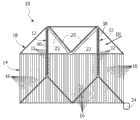
-Fig. 1 is the perspective schematic view according to photovoltaic system of the present invention;
-Fig. 2 is the schematic side elevation of the system of Fig. 1;
-Fig. 3 is the part perspective view by the more vast scale of the indicated part of the arrow III among Fig. 1;
-Fig. 4 is the profile perspective of the receiver of Fig. 3;
-Fig. 5,6 and 7 is respectively according to line V-V, the VI-VI of Fig. 3 and the section of VII-VII;
-Fig. 8 and 9 is according to the arrow VIII of Fig. 7 and the view of IX;
-Figure 10 is the section according to the line X-X of Fig. 7; And
-Figure 11 shows the schematic cross-section of a kind of modification of Fig. 7.
Embodiment
With reference to Fig. 1 and 2, the high photovoltaic system of assembling according to the present invention is indicated by 10.
This photovoltaic system 10 comprises at least one photovoltaic receiver 12 and is arranged to the reflection unit 14 of solar energy collecting on photovoltaic receiver 12.Provide two photovoltaic receivers 12 in the example shown in the figure, but should be understood that, the number of described photovoltaic receiver can be as requested and/or design variable and changing.
The framework of carrying speculum 16 carries (carry) supporting construction 18 in addition, and photovoltaic receiver 12 is fixed to the upper, and described photovoltaic receiver 12 is set at the fixed range place from reflection unit 14.Each photovoltaic receiver 12 all has elongated shape, and is parallel to the reflecting surface extension of speculum 16.The length of photovoltaic receiver 12 is substantially equal to the length of speculum 16.Supporting construction 18 comprises the pipeline that passes through (duct) 20 of the electric conductor (conductor) that is used to be connected to each photovoltaic receiver and the pipeline that passes through 22 that is used for the cooling agent of photovoltaic receiver 12.
What indicate is to point to (pointing) system by 24 to be used as an integral body in Fig. 1 and Fig. 2, the orientation of each speculum 16 around corresponding axis controlled in its position according to the sun, thereby makes these speculums 16 to keep the solar radiation of being reflected to focus on all the time on the corresponding receiver 12.In order to realize the orientation of each speculum 16 around corresponding axis, the single electric motor that is connected to each speculum 16 by means of carriage (rack) system that transmits the identical anglec of rotation to all speculums for example can be provided, guarantee always it can begin from different initial angle positions that institute's radiation reflected will keep accumulating on the photovoltaic receiver 12 and no matter the moving of the sun.The framework hinged (articulate) of carrying speculum 16 to around with the fixation wall of the axle of the rotating shaft direct cross of speculum 16 on.Pointing system 24 is controlled at and is used as an integral body among Fig. 2 by 26 actuators of indicating (actuator), its change reflection unit 14 about the angle of vertical plane in case reflection unit 14 maintenances all the time with sun quadrature.Actuator 26 changes comprise the inclination angle (inclination) of the plane of speculum 16 about vertical plane, so that realize the mobile zenith (zenithal) that carries out of the sun are followed the tracks of.
With reference to Fig. 3 and Fig. 4, each photovoltaic receiver 12 is included in the tubular body 28 that prolongs on the longitudinal direction 30.At a plurality of (strip) of described main body 28 internal fixation photovoltaic materials 32, it extends on the direction about longitudinal direction 30 crosscuts (transverse).The bar of photovoltaic material 32 is parallel to each other, and is configured on longitudinal direction 30 at a distance from each other.On the outer surface of tubular body 28, provide a plurality of lens 34.The solar radiation that described lens 34 receive by speculum 16 reflections, and described solar radiation is focused on the bar of photovoltaic material 32.The lens 34 that are associated with each bar of photovoltaic material 32 preferably are provided.The given shape of focal zone 32 makes it possible to production bar shaped photovoltaic element, and it is particular importance in the production of photovoltaic cell.
With reference to Fig. 5 and Fig. 6, lens 34 occupy the whole length of tubular body 28 in a longitudinal direction, and the bar of photovoltaic material 32 only occupies the least part on the parallel surface of tubular body 28 and lens 34.Although very little by the surface that the bar of photovoltaic material 32 occupies, the whole solar radiation that impinges upon on the lens 34 all is collected on the bar of photovoltaic material 32.This layout makes it possible to obtain for the photovoltaic material of per unit area the solar energy of high gathering.
Such high-energy is assembled the remarkable rising of certainty with the temperature of photovoltaic receiver 12.The output that described temperature rising meeting is handled photovoltaic causes adverse effect.According to favorable characteristics of the present invention, the heat that can dissipate and produce by means of coolant circulating in tubular body 28 owing to the gathering of solar energy on photovoltaic receiver 12.The bar of photovoltaic material 32 is immersed in the cooling agent.The heat energy that is extracted by means of cooling agent by photovoltaic receiver 12 can be used to produce the hot water that for example uses for dwelling house.Can the zone that is not exposed to solar radiation of photovoltaic receiver 12 is adiabatic, so that minimizing is towards the heat radiation of external environment condition.The main body 28 of photovoltaic receiver 12 is connected to the pipeline 22 of supporting construction 18 by hydraulic transmission mode (hydraulically), so that realize the circulate coolant towards the outside.
From the viewpoint of structure, tubular body 28 can be by forming at a plurality of sections (section) 38 fixed to one another, identical from one another of axially going up along corresponding preceding border (front edge).Each section 38 has corresponding lens 34 and carries corresponding of photovoltaic material 32.Fig. 7 shows one of described section 38 to Figure 10.Section 38 can be made by injection-molded plastic material, and can by means of gluing, the welding or the like fixed to one another.Each section 38 provides the bearing (seat) 40 relative with lens 34.Form vertical shell about each bearing 40 aligned with each other, inserted base therein as thin plate 42 shapes, thereon fixedly photovoltaic material each 32.Base 42 carries the electrical connection of the bar of photovoltaic material 32.
With reference to Figure 11, may wish to reduce the size (dimension) of the cross section of photovoltaic receiver 12 in some applications, so that reduce the volume of transparent heat media (thermovector) liquid.For described purpose, can set curved reflectors 44 in tubular body 28 inside, it receives from the radiation of lens 34 and reflects it on the bar of photovoltaic material 32.This solution makes it possible to make photovoltaic receiver 12 according to compacter form.
It is contemplated that be applicable to have in the another kind configuration of above-mentioned receiver of low (medium-to-low) system of assembling, to be used for only holding cylindrical lens rather than a series of sphere lens that (housing) has the longitudinal axis, it provides elongated focal zone, and the bar shaped photovoltaic element that prolongs on the y direction of receiver will be disposed in the described elongated focal zone.
Claims (15)
1. one kind high gathering photovoltaic system, it comprises at least one photovoltaic receiver (12) and is arranged to the reflection unit (14) of solar energy collecting on described photovoltaic receiver (12), it is characterized in that, photovoltaic receiver (12) is included in longitudinal direction (30) and goes up the tubular body (28) that prolongs, accommodate photovoltaic material (32) therein, described supportive body (28) is provided with at least one lens (34), and it is arranged to go up a reflected solar radiation from described reflection unit (14) at described photovoltaic material (32) and focuses at least one bar shaped focal zone.
2. photovoltaic system according to claim 1 is characterized in that, described photovoltaic system comprises a plurality of that are fixed on the interior photovoltaic material (32) of described main body (28).
3. photovoltaic system according to claim 2 is characterized in that, the bar of described photovoltaic material (32) is arranged about described longitudinal direction (30) crosscut and is configured at a distance from each other on described direction (30).
4. photovoltaic system according to claim 3 is characterized in that, described supportive body (28) comprises a plurality of sphere lenses (34).
5. photovoltaic system according to claim 1 is characterized in that, described photovoltaic system comprises at least one bar that is arranged to about the parallel photovoltaic material of described longitudinal direction (30).
6. photovoltaic system according to claim 1 is characterized in that, described supportive body (28) comprises at least one cylindrical lens that is parallel to described longitudinal direction (30).
7. photovoltaic system according to claim 1 is characterized in that, makes cooling agent flow in described tubular body (28).
8. photovoltaic system according to claim 2 is characterized in that, each bar of photovoltaic material (32) is associated with corresponding lens (34).
9. photovoltaic system according to claim 4 is characterized in that, described tubular body (28) comprises that each section (38) has corresponding lens (34) along corresponding front surface a plurality of axial section fixed to one another.
10. according to the described photovoltaic system of aforementioned each claim, it is characterized in that, being contained in the described tubular body (28) is speculum (44), and described speculum (44) receives the solar radiation that is focused on by described lens (34) and reflects it on the bar of described photovoltaic material (32).
11. according to the described photovoltaic system of aforementioned each claim, it is characterized in that, described reflection unit (14) comprises a plurality of elongated speculum (16) parallel to each other, and it can be directed to be used for that solar radiation is kept focusing on all the time described receiver (12).
12. photovoltaic system according to claim 11 is characterized in that, the reflecting surface that described photovoltaic receiver (12) is parallel to described speculum (16) extends.
13. photovoltaic system according to claim 11, it is characterized in that, described photovoltaic system comprises sensing and the regulating system with two degrees of freedom, is used for moving orienting reflex device (14) and being used for centering on next directed each speculum (16) of corresponding rotating shaft according to the orientation of the sun.
14., it is characterized in that described photovoltaic system comprises supporting construction (18) according to the described photovoltaic system of aforementioned each claim, be used for supporting described at least one photovoltaic receiver (12) at fixed range place from described reflection unit (14).
15. photovoltaic system according to claim 9 is characterized in that, described supporting construction (18) comprises pipeline (20,22), is used for passing through and being used for passing through of cooling agent of electric conductor.
Applications Claiming Priority (1)
| Application Number | Priority Date | Filing Date | Title |
|---|---|---|---|
| PCT/IT2008/000539 WO2010016076A1 (en) | 2008-08-07 | 2008-08-07 | High-concentration photovoltaic system |
Publications (1)
| Publication Number | Publication Date |
|---|---|
| CN102113134A true CN102113134A (en) | 2011-06-29 |
Family
ID=40344758
Family Applications (1)
| Application Number | Title | Priority Date | Filing Date |
|---|---|---|---|
| CN2008801306500A Pending CN102113134A (en) | 2008-08-07 | 2008-08-07 | High-concentration photovoltaic system |
Country Status (6)
| Country | Link |
|---|---|
| US (1) | US20110232720A1 (en) |
| EP (1) | EP2308099A1 (en) |
| JP (1) | JP5250111B2 (en) |
| CN (1) | CN102113134A (en) |
| TN (1) | TN2010000605A1 (en) |
| WO (1) | WO2010016076A1 (en) |
Cited By (1)
| Publication number | Priority date | Publication date | Assignee | Title |
|---|---|---|---|---|
| CN104300893A (en) * | 2014-08-18 | 2015-01-21 | 杭州慈源科技有限公司 | Double-sided power generation solar battery assembly with polygonal structure |
Families Citing this family (4)
| Publication number | Priority date | Publication date | Assignee | Title |
|---|---|---|---|---|
| KR20110013989A (en) * | 2009-08-04 | 2011-02-10 | 삼성전자주식회사 | Solar cell module and method of manufacturing the same |
| TWI425378B (en) * | 2011-04-14 | 2014-02-01 | Atomic Energy Council | Method for deploying a concentrating photovoltaic system |
| CN103456823B (en) * | 2013-04-28 | 2016-04-20 | 刘庆云 | A kind of tubulose condensation photovoltaic battery component |
| CN103456824A (en) * | 2013-08-08 | 2013-12-18 | 刘庆云 | Tubular tracking concentrating photovoltaic module |
Family Cites Families (9)
| Publication number | Priority date | Publication date | Assignee | Title |
|---|---|---|---|---|
| IT1193452B (en) | 1979-07-20 | 1988-06-22 | Mantinger Karl | SOLAR PANEL CONCENTRATION VIA ADJUSTABLE FLAT MIRRORS |
| DE3109284A1 (en) * | 1981-03-11 | 1982-09-30 | Interatom Internationale Atomreaktorbau Gmbh, 5060 Bergisch Gladbach | Solar power station with photovoltaic cells |
| JPH03263549A (en) * | 1990-03-13 | 1991-11-25 | Kyocera Corp | Solar energy collector |
| US5882434A (en) * | 1996-10-15 | 1999-03-16 | United Solar Technologies, Inc. | Solar concentrator having an offset parabolic configuration |
| US7208674B2 (en) * | 2001-09-11 | 2007-04-24 | Eric Aylaian | Solar cell having photovoltaic cells inclined at acute angle to each other |
| DE60230335D1 (en) * | 2002-06-21 | 2009-01-22 | Kyosemi Corp | LIGHT RECEPTOR OR LIGHT EMITTING DEVICE AND METHOD FOR THE PRODUCTION THEREOF |
| JP2004172256A (en) * | 2002-11-19 | 2004-06-17 | Daido Steel Co Ltd | Solar power generating device of linear light condensing-type |
| ITMI20041073A1 (en) * | 2004-05-27 | 2004-08-27 | Reginald Ian Williams | SOLAR ENERGY GENERATOR AND SYSTEM AND PROCEDURE FOR ITS CONTROL |
| US20060243319A1 (en) * | 2005-04-29 | 2006-11-02 | Arizona Public Service Company | Clustered solar-energy conversion array and method therefor |
-
2008
- 2008-08-07 WO PCT/IT2008/000539 patent/WO2010016076A1/en active Application Filing
- 2008-08-07 JP JP2011521690A patent/JP5250111B2/en not_active Expired - Fee Related
- 2008-08-07 CN CN2008801306500A patent/CN102113134A/en active Pending
- 2008-08-07 US US13/057,990 patent/US20110232720A1/en not_active Abandoned
- 2008-08-07 EP EP08876017A patent/EP2308099A1/en not_active Withdrawn
-
2010
- 2010-12-27 TN TNP2010000605A patent/TN2010000605A1/en unknown
Cited By (1)
| Publication number | Priority date | Publication date | Assignee | Title |
|---|---|---|---|---|
| CN104300893A (en) * | 2014-08-18 | 2015-01-21 | 杭州慈源科技有限公司 | Double-sided power generation solar battery assembly with polygonal structure |
Also Published As
| Publication number | Publication date |
|---|---|
| EP2308099A1 (en) | 2011-04-13 |
| JP2011530805A (en) | 2011-12-22 |
| TN2010000605A1 (en) | 2012-05-24 |
| US20110232720A1 (en) | 2011-09-29 |
| JP5250111B2 (en) | 2013-07-31 |
| WO2010016076A1 (en) | 2010-02-11 |
Similar Documents
| Publication | Publication Date | Title |
|---|---|---|
| EP2559955B1 (en) | Solar heat collecting system | |
| JP4878354B2 (en) | Solar cell device and solar cell system | |
| US3985119A (en) | Solar heat collector | |
| KR100818197B1 (en) | Solar focus type generation apparatus | |
| CN102113134A (en) | High-concentration photovoltaic system | |
| CN101858649A (en) | Fresnel solar collector | |
| CN103238033A (en) | A solar energy collector system | |
| US20110259319A1 (en) | Solar Energy Absorber | |
| US20160268968A1 (en) | Solar Collecting Device | |
| JP2013029537A (en) | Concentrator and concentration apparatus including the same | |
| CN101839561A (en) | Solar multi-directional tracking vacuum tube utilization system | |
| US8474445B2 (en) | Concentrating solar energy device | |
| CN101839617A (en) | Solar multi-directional tracking solar energy drying equipment | |
| JP2005106432A (en) | Solar light collection and heat collection device | |
| JP2011530805A5 (en) | ||
| CN201503149U (en) | Solar energy multidirectional tracking heat pipe utilization system | |
| JP4655313B2 (en) | Solar concentrator | |
| EP2591293B1 (en) | A device for collecting solar energy | |
| KR101407079B1 (en) | solar heat collecting system using cone shape reflector | |
| JP2005062785A (en) | Tracking type beam condensing unit | |
| JPS59100349A (en) | Solar heat collector | |
| CN1049278C (en) | Translationally tracking solar energy collector | |
| KR101111975B1 (en) | heat storage device using a parabolic mirror | |
| KR102253151B1 (en) | Solar water heater with refector | |
| CN201504198U (en) | Solar energy multidirectional tracking stirling engine power generation system |
Legal Events
| Date | Code | Title | Description |
|---|---|---|---|
| C06 | Publication | ||
| PB01 | Publication | ||
| C10 | Entry into substantive examination | ||
| SE01 | Entry into force of request for substantive examination | ||
| AD01 | Patent right deemed abandoned |
Effective date of abandoning: 20110629 |
|
| C20 | Patent right or utility model deemed to be abandoned or is abandoned |