CN102089598A - Solar concentrating mirror - Google Patents
Solar concentrating mirror Download PDFInfo
- Publication number
- CN102089598A CN102089598A CN2009801275174A CN200980127517A CN102089598A CN 102089598 A CN102089598 A CN 102089598A CN 2009801275174 A CN2009801275174 A CN 2009801275174A CN 200980127517 A CN200980127517 A CN 200980127517A CN 102089598 A CN102089598 A CN 102089598A
- Authority
- CN
- China
- Prior art keywords
- light
- layer
- solar cell
- goods
- solar
- Prior art date
- Legal status (The legal status is an assumption and is not a legal conclusion. Google has not performed a legal analysis and makes no representation as to the accuracy of the status listed.)
- Pending
Links
- 239000012788 optical film Substances 0.000 claims abstract description 53
- 239000011241 protective layer Substances 0.000 claims abstract description 48
- 239000000463 material Substances 0.000 claims abstract description 34
- 239000010410 layer Substances 0.000 claims description 224
- 229920000642 polymer Polymers 0.000 claims description 89
- 230000003287 optical effect Effects 0.000 claims description 67
- 238000010521 absorption reaction Methods 0.000 claims description 47
- 239000010408 film Substances 0.000 claims description 37
- 238000000576 coating method Methods 0.000 claims description 34
- 239000011248 coating agent Substances 0.000 claims description 33
- 238000002310 reflectometry Methods 0.000 claims description 12
- 150000001875 compounds Chemical class 0.000 claims description 10
- 229910021419 crystalline silicon Inorganic materials 0.000 claims description 10
- 238000000034 method Methods 0.000 claims description 8
- 239000004926 polymethyl methacrylate Substances 0.000 claims description 8
- 238000001228 spectrum Methods 0.000 claims description 8
- 239000000758 substrate Substances 0.000 claims description 8
- 239000003963 antioxidant agent Substances 0.000 claims description 7
- 230000003078 antioxidant effect Effects 0.000 claims description 7
- 230000005540 biological transmission Effects 0.000 claims description 7
- 229920003229 poly(methyl methacrylate) Polymers 0.000 claims description 7
- 229920001973 fluoroelastomer Polymers 0.000 claims description 6
- 229910001218 Gallium arsenide Inorganic materials 0.000 claims description 5
- 230000004446 light reflex Effects 0.000 claims description 5
- 239000004611 light stabiliser Substances 0.000 claims description 5
- 230000011514 reflex Effects 0.000 claims description 5
- 150000001412 amines Chemical class 0.000 claims description 4
- 239000003063 flame retardant Substances 0.000 claims description 4
- 230000003068 static effect Effects 0.000 claims description 4
- 238000012546 transfer Methods 0.000 claims description 4
- 239000002131 composite material Substances 0.000 claims description 3
- 239000005357 flat glass Substances 0.000 claims description 3
- 239000006260 foam Substances 0.000 claims description 3
- 238000002347 injection Methods 0.000 claims description 3
- 239000007924 injection Substances 0.000 claims description 3
- 239000011229 interlayer Substances 0.000 claims description 3
- 229920005594 polymer fiber Polymers 0.000 claims description 3
- 230000002787 reinforcement Effects 0.000 claims description 3
- 239000006097 ultraviolet radiation absorber Substances 0.000 claims description 3
- MARUHZGHZWCEQU-UHFFFAOYSA-N 5-phenyl-2h-tetrazole Chemical compound C1=CC=CC=C1C1=NNN=N1 MARUHZGHZWCEQU-UHFFFAOYSA-N 0.000 claims description 2
- 239000006081 fluorescent whitening agent Substances 0.000 claims description 2
- 239000002245 particle Substances 0.000 claims description 2
- 229910021420 polycrystalline silicon Inorganic materials 0.000 claims description 2
- 229920005591 polysilicon Polymers 0.000 claims description 2
- 229920002100 high-refractive-index polymer Polymers 0.000 claims 1
- 230000007246 mechanism Effects 0.000 abstract description 8
- 230000002708 enhancing effect Effects 0.000 abstract description 4
- 230000002411 adverse Effects 0.000 abstract description 2
- 238000010276 construction Methods 0.000 abstract description 2
- 230000015556 catabolic process Effects 0.000 abstract 1
- 238000006731 degradation reaction Methods 0.000 abstract 1
- 210000004027 cell Anatomy 0.000 description 120
- 230000009102 absorption Effects 0.000 description 35
- LYCAIKOWRPUZTN-UHFFFAOYSA-N Ethylene glycol Chemical compound OCCO LYCAIKOWRPUZTN-UHFFFAOYSA-N 0.000 description 22
- 238000005266 casting Methods 0.000 description 20
- 229920005644 polyethylene terephthalate glycol copolymer Polymers 0.000 description 20
- 229920001577 copolymer Polymers 0.000 description 19
- 239000000203 mixture Substances 0.000 description 18
- 238000012360 testing method Methods 0.000 description 18
- 230000005670 electromagnetic radiation Effects 0.000 description 16
- 239000000178 monomer Substances 0.000 description 14
- 230000005855 radiation Effects 0.000 description 14
- 230000006866 deterioration Effects 0.000 description 13
- 230000004224 protection Effects 0.000 description 13
- 230000002745 absorbent Effects 0.000 description 12
- 239000002250 absorbent Substances 0.000 description 12
- 230000008859 change Effects 0.000 description 12
- 238000005259 measurement Methods 0.000 description 11
- VYPSYNLAJGMNEJ-UHFFFAOYSA-N Silicium dioxide Chemical compound O=[Si]=O VYPSYNLAJGMNEJ-UHFFFAOYSA-N 0.000 description 10
- 229920002313 fluoropolymer Polymers 0.000 description 10
- 239000004811 fluoropolymer Substances 0.000 description 10
- -1 Merlon Polymers 0.000 description 9
- 239000000654 additive Substances 0.000 description 9
- 230000000694 effects Effects 0.000 description 9
- 230000004927 fusion Effects 0.000 description 9
- 239000002033 PVDF binder Substances 0.000 description 8
- 229920010524 Syndiotactic polystyrene Polymers 0.000 description 8
- 230000000996 additive effect Effects 0.000 description 8
- WGCNASOHLSPBMP-UHFFFAOYSA-N hydroxyacetaldehyde Natural products OCC=O WGCNASOHLSPBMP-UHFFFAOYSA-N 0.000 description 8
- 229920000728 polyester Polymers 0.000 description 8
- 229920002981 polyvinylidene fluoride Polymers 0.000 description 8
- 238000010586 diagram Methods 0.000 description 7
- 239000000126 substance Substances 0.000 description 7
- XLOMVQKBTHCTTD-UHFFFAOYSA-N zinc oxide Inorganic materials [Zn]=O XLOMVQKBTHCTTD-UHFFFAOYSA-N 0.000 description 7
- PPBRXRYQALVLMV-UHFFFAOYSA-N Styrene Chemical compound C=CC1=CC=CC=C1 PPBRXRYQALVLMV-UHFFFAOYSA-N 0.000 description 6
- 230000032683 aging Effects 0.000 description 6
- 238000006243 chemical reaction Methods 0.000 description 6
- 229910052724 xenon Inorganic materials 0.000 description 6
- FHNFHKCVQCLJFQ-UHFFFAOYSA-N xenon atom Chemical compound [Xe] FHNFHKCVQCLJFQ-UHFFFAOYSA-N 0.000 description 6
- 238000002835 absorbance Methods 0.000 description 5
- 239000000853 adhesive Substances 0.000 description 5
- 230000001070 adhesive effect Effects 0.000 description 5
- 239000012790 adhesive layer Substances 0.000 description 5
- 150000001733 carboxylic acid esters Chemical class 0.000 description 5
- 238000013007 heat curing Methods 0.000 description 5
- 239000002105 nanoparticle Substances 0.000 description 5
- 238000002360 preparation method Methods 0.000 description 5
- 230000001105 regulatory effect Effects 0.000 description 5
- CURLTUGMZLYLDI-UHFFFAOYSA-N Carbon dioxide Chemical compound O=C=O CURLTUGMZLYLDI-UHFFFAOYSA-N 0.000 description 4
- VVQNEPGJFQJSBK-UHFFFAOYSA-N Methyl methacrylate Chemical compound COC(=O)C(C)=C VVQNEPGJFQJSBK-UHFFFAOYSA-N 0.000 description 4
- KKEYFWRCBNTPAC-UHFFFAOYSA-N Terephthalic acid Chemical compound OC(=O)C1=CC=C(C(O)=O)C=C1 KKEYFWRCBNTPAC-UHFFFAOYSA-N 0.000 description 4
- 238000005516 engineering process Methods 0.000 description 4
- 229920001519 homopolymer Polymers 0.000 description 4
- 239000004576 sand Substances 0.000 description 4
- NIXOWILDQLNWCW-UHFFFAOYSA-N 2-Propenoic acid Natural products OC(=O)C=C NIXOWILDQLNWCW-UHFFFAOYSA-N 0.000 description 3
- UHOVQNZJYSORNB-UHFFFAOYSA-N Benzene Chemical compound C1=CC=CC=C1 UHOVQNZJYSORNB-UHFFFAOYSA-N 0.000 description 3
- 241001424688 Enceliopsis Species 0.000 description 3
- JIGUQPWFLRLWPJ-UHFFFAOYSA-N Ethyl acrylate Chemical compound CCOC(=O)C=C JIGUQPWFLRLWPJ-UHFFFAOYSA-N 0.000 description 3
- 239000004433 Thermoplastic polyurethane Substances 0.000 description 3
- 229920006397 acrylic thermoplastic Polymers 0.000 description 3
- 230000003044 adaptive effect Effects 0.000 description 3
- 230000008901 benefit Effects 0.000 description 3
- 150000007942 carboxylates Chemical class 0.000 description 3
- 238000011161 development Methods 0.000 description 3
- 230000018109 developmental process Effects 0.000 description 3
- 230000003670 easy-to-clean Effects 0.000 description 3
- 230000009477 glass transition Effects 0.000 description 3
- FPYJFEHAWHCUMM-UHFFFAOYSA-N maleic anhydride Chemical compound O=C1OC(=O)C=C1 FPYJFEHAWHCUMM-UHFFFAOYSA-N 0.000 description 3
- 238000003801 milling Methods 0.000 description 3
- PNJWIWWMYCMZRO-UHFFFAOYSA-N pent‐4‐en‐2‐one Natural products CC(=O)CC=C PNJWIWWMYCMZRO-UHFFFAOYSA-N 0.000 description 3
- 238000007539 photo-oxidation reaction Methods 0.000 description 3
- 229920001483 poly(ethyl methacrylate) polymer Polymers 0.000 description 3
- 229920000515 polycarbonate Polymers 0.000 description 3
- 239000004417 polycarbonate Substances 0.000 description 3
- 229920000098 polyolefin Polymers 0.000 description 3
- 229920001296 polysiloxane Polymers 0.000 description 3
- 230000002028 premature Effects 0.000 description 3
- 230000008569 process Effects 0.000 description 3
- 230000001932 seasonal effect Effects 0.000 description 3
- 239000000377 silicon dioxide Substances 0.000 description 3
- 239000003381 stabilizer Substances 0.000 description 3
- ISXSCDLOGDJUNJ-UHFFFAOYSA-N tert-butyl prop-2-enoate Chemical compound CC(C)(C)OC(=O)C=C ISXSCDLOGDJUNJ-UHFFFAOYSA-N 0.000 description 3
- 229920002803 thermoplastic polyurethane Polymers 0.000 description 3
- 239000011787 zinc oxide Substances 0.000 description 3
- LEVFXWNQQSSNAC-UHFFFAOYSA-N 2-(4,6-diphenyl-1,3,5-triazin-2-yl)-5-hexoxyphenol Chemical compound OC1=CC(OCCCCCC)=CC=C1C1=NC(C=2C=CC=CC=2)=NC(C=2C=CC=CC=2)=N1 LEVFXWNQQSSNAC-UHFFFAOYSA-N 0.000 description 2
- NIXOWILDQLNWCW-UHFFFAOYSA-M Acrylate Chemical compound [O-]C(=O)C=C NIXOWILDQLNWCW-UHFFFAOYSA-M 0.000 description 2
- 101100082837 Arabidopsis thaliana PEN1 gene Proteins 0.000 description 2
- SOGAXMICEFXMKE-UHFFFAOYSA-N Butylmethacrylate Chemical compound CCCCOC(=O)C(C)=C SOGAXMICEFXMKE-UHFFFAOYSA-N 0.000 description 2
- 229920003313 Bynel® Polymers 0.000 description 2
- 229920001634 Copolyester Polymers 0.000 description 2
- MQIUGAXCHLFZKX-UHFFFAOYSA-N Di-n-octyl phthalate Natural products CCCCCCCCOC(=O)C1=CC=CC=C1C(=O)OCCCCCCCC MQIUGAXCHLFZKX-UHFFFAOYSA-N 0.000 description 2
- 229920005439 Perspex® Polymers 0.000 description 2
- 229920005372 Plexiglas® Polymers 0.000 description 2
- 239000004743 Polypropylene Substances 0.000 description 2
- 229910000831 Steel Inorganic materials 0.000 description 2
- GWEVSGVZZGPLCZ-UHFFFAOYSA-N Titan oxide Chemical compound O=[Ti]=O GWEVSGVZZGPLCZ-UHFFFAOYSA-N 0.000 description 2
- 238000003848 UV Light-Curing Methods 0.000 description 2
- 230000006750 UV protection Effects 0.000 description 2
- 238000000862 absorption spectrum Methods 0.000 description 2
- 239000002390 adhesive tape Substances 0.000 description 2
- WNLRTRBMVRJNCN-UHFFFAOYSA-N adipic acid Chemical compound OC(=O)CCCCC(O)=O WNLRTRBMVRJNCN-UHFFFAOYSA-N 0.000 description 2
- 125000000217 alkyl group Chemical group 0.000 description 2
- 239000004411 aluminium Substances 0.000 description 2
- 229910052782 aluminium Inorganic materials 0.000 description 2
- XAGFODPZIPBFFR-UHFFFAOYSA-N aluminium Chemical compound [Al] XAGFODPZIPBFFR-UHFFFAOYSA-N 0.000 description 2
- QVGXLLKOCUKJST-UHFFFAOYSA-N atomic oxygen Chemical compound [O] QVGXLLKOCUKJST-UHFFFAOYSA-N 0.000 description 2
- 229920005601 base polymer Polymers 0.000 description 2
- BJQHLKABXJIVAM-UHFFFAOYSA-N bis(2-ethylhexyl) phthalate Chemical compound CCCCC(CC)COC(=O)C1=CC=CC=C1C(=O)OCC(CC)CCCC BJQHLKABXJIVAM-UHFFFAOYSA-N 0.000 description 2
- IISBACLAFKSPIT-UHFFFAOYSA-N bisphenol A Chemical compound C=1C=C(O)C=CC=1C(C)(C)C1=CC=C(O)C=C1 IISBACLAFKSPIT-UHFFFAOYSA-N 0.000 description 2
- 239000007767 bonding agent Substances 0.000 description 2
- BEWYHVAWEKZDPP-UHFFFAOYSA-N bornane Chemical compound C1CC2(C)CCC1C2(C)C BEWYHVAWEKZDPP-UHFFFAOYSA-N 0.000 description 2
- WERYXYBDKMZEQL-UHFFFAOYSA-N butane-1,4-diol Chemical compound OCCCCO WERYXYBDKMZEQL-UHFFFAOYSA-N 0.000 description 2
- 239000001569 carbon dioxide Substances 0.000 description 2
- 229910002092 carbon dioxide Inorganic materials 0.000 description 2
- 239000003795 chemical substances by application Substances 0.000 description 2
- 230000000052 comparative effect Effects 0.000 description 2
- 230000001143 conditioned effect Effects 0.000 description 2
- 238000001723 curing Methods 0.000 description 2
- 125000004122 cyclic group Chemical group 0.000 description 2
- 125000000118 dimethyl group Chemical group [H]C([H])([H])* 0.000 description 2
- 150000002148 esters Chemical group 0.000 description 2
- UHESRSKEBRADOO-UHFFFAOYSA-N ethyl carbamate;prop-2-enoic acid Chemical compound OC(=O)C=C.CCOC(N)=O UHESRSKEBRADOO-UHFFFAOYSA-N 0.000 description 2
- 239000013529 heat transfer fluid Substances 0.000 description 2
- 230000002209 hydrophobic effect Effects 0.000 description 2
- 230000007774 longterm Effects 0.000 description 2
- 229910052751 metal Inorganic materials 0.000 description 2
- 239000002184 metal Substances 0.000 description 2
- 125000002496 methyl group Chemical group [H]C([H])([H])* 0.000 description 2
- 238000000386 microscopy Methods 0.000 description 2
- 239000003595 mist Substances 0.000 description 2
- 238000012986 modification Methods 0.000 description 2
- 230000004048 modification Effects 0.000 description 2
- ORECYURYFJYPKY-UHFFFAOYSA-N n,n'-bis(2,2,6,6-tetramethylpiperidin-4-yl)hexane-1,6-diamine;2,4,6-trichloro-1,3,5-triazine;2,4,4-trimethylpentan-2-amine Chemical compound CC(C)(C)CC(C)(C)N.ClC1=NC(Cl)=NC(Cl)=N1.C1C(C)(C)NC(C)(C)CC1NCCCCCCNC1CC(C)(C)NC(C)(C)C1 ORECYURYFJYPKY-UHFFFAOYSA-N 0.000 description 2
- RXOHFPCZGPKIRD-UHFFFAOYSA-N naphthalene-2,6-dicarboxylic acid Chemical compound C1=C(C(O)=O)C=CC2=CC(C(=O)O)=CC=C21 RXOHFPCZGPKIRD-UHFFFAOYSA-N 0.000 description 2
- BDJRBEYXGGNYIS-UHFFFAOYSA-N nonanedioic acid Chemical compound OC(=O)CCCCCCCC(O)=O BDJRBEYXGGNYIS-UHFFFAOYSA-N 0.000 description 2
- 239000003921 oil Substances 0.000 description 2
- 229910052760 oxygen Inorganic materials 0.000 description 2
- 239000001301 oxygen Substances 0.000 description 2
- 239000003973 paint Substances 0.000 description 2
- 230000002688 persistence Effects 0.000 description 2
- XNGIFLGASWRNHJ-UHFFFAOYSA-N phthalic acid Chemical compound OC(=O)C1=CC=CC=C1C(O)=O XNGIFLGASWRNHJ-UHFFFAOYSA-N 0.000 description 2
- 229920003023 plastic Polymers 0.000 description 2
- 239000004033 plastic Substances 0.000 description 2
- 229920000647 polyepoxide Polymers 0.000 description 2
- 229920001155 polypropylene Polymers 0.000 description 2
- 229920002635 polyurethane Polymers 0.000 description 2
- 239000004814 polyurethane Substances 0.000 description 2
- 238000011160 research Methods 0.000 description 2
- CXMXRPHRNRROMY-UHFFFAOYSA-N sebacic acid Chemical compound OC(=O)CCCCCCCCC(O)=O CXMXRPHRNRROMY-UHFFFAOYSA-N 0.000 description 2
- 239000004065 semiconductor Substances 0.000 description 2
- 229920005573 silicon-containing polymer Polymers 0.000 description 2
- 230000003595 spectral effect Effects 0.000 description 2
- 239000010959 steel Substances 0.000 description 2
- 125000000999 tert-butyl group Chemical group [H]C([H])([H])C(*)(C([H])([H])[H])C([H])([H])[H] 0.000 description 2
- 229920001169 thermoplastic Polymers 0.000 description 2
- 239000004416 thermosoftening plastic Substances 0.000 description 2
- OGIDPMRJRNCKJF-UHFFFAOYSA-N titanium oxide Inorganic materials [Ti]=O OGIDPMRJRNCKJF-UHFFFAOYSA-N 0.000 description 2
- ARCGXLSVLAOJQL-UHFFFAOYSA-N trimellitic acid Chemical compound OC(=O)C1=CC=C(C(O)=O)C(C(O)=O)=C1 ARCGXLSVLAOJQL-UHFFFAOYSA-N 0.000 description 2
- BQCIDUSAKPWEOX-UHFFFAOYSA-N 1,1-Difluoroethene Chemical compound FC(F)=C BQCIDUSAKPWEOX-UHFFFAOYSA-N 0.000 description 1
- IGGDKDTUCAWDAN-UHFFFAOYSA-N 1-vinylnaphthalene Chemical compound C1=CC=C2C(C=C)=CC=CC2=C1 IGGDKDTUCAWDAN-UHFFFAOYSA-N 0.000 description 1
- SMZOUWXMTYCWNB-UHFFFAOYSA-N 2-(2-methoxy-5-methylphenyl)ethanamine Chemical compound COC1=CC=C(C)C=C1CCN SMZOUWXMTYCWNB-UHFFFAOYSA-N 0.000 description 1
- QPGBFKDHRXJSIK-UHFFFAOYSA-N 2-tert-butylbenzene-1,3-dicarboxylic acid Chemical compound CC(C)(C)C1=C(C(O)=O)C=CC=C1C(O)=O QPGBFKDHRXJSIK-UHFFFAOYSA-N 0.000 description 1
- AIBRSVLEQRWAEG-UHFFFAOYSA-N 3,9-bis(2,4-ditert-butylphenoxy)-2,4,8,10-tetraoxa-3,9-diphosphaspiro[5.5]undecane Chemical compound CC(C)(C)C1=CC(C(C)(C)C)=CC=C1OP1OCC2(COP(OC=3C(=CC(=CC=3)C(C)(C)C)C(C)(C)C)OC2)CO1 AIBRSVLEQRWAEG-UHFFFAOYSA-N 0.000 description 1
- NEQFBGHQPUXOFH-UHFFFAOYSA-N 4-(4-carboxyphenyl)benzoic acid Chemical compound C1=CC(C(=O)O)=CC=C1C1=CC=C(C(O)=O)C=C1 NEQFBGHQPUXOFH-UHFFFAOYSA-N 0.000 description 1
- DEXFNLNNUZKHNO-UHFFFAOYSA-N 6-[3-[4-[2-(2,3-dihydro-1H-inden-2-ylamino)pyrimidin-5-yl]piperidin-1-yl]-3-oxopropyl]-3H-1,3-benzoxazol-2-one Chemical compound C1C(CC2=CC=CC=C12)NC1=NC=C(C=N1)C1CCN(CC1)C(CCC1=CC2=C(NC(O2)=O)C=C1)=O DEXFNLNNUZKHNO-UHFFFAOYSA-N 0.000 description 1
- 239000004925 Acrylic resin Substances 0.000 description 1
- 229920000178 Acrylic resin Polymers 0.000 description 1
- KXDHJXZQYSOELW-UHFFFAOYSA-M Carbamate Chemical compound NC([O-])=O KXDHJXZQYSOELW-UHFFFAOYSA-M 0.000 description 1
- UGFAIRIUMAVXCW-UHFFFAOYSA-N Carbon monoxide Chemical group [O+]#[C-] UGFAIRIUMAVXCW-UHFFFAOYSA-N 0.000 description 1
- 240000001829 Catharanthus roseus Species 0.000 description 1
- 229910004613 CdTe Inorganic materials 0.000 description 1
- 101100440919 Escherichia phage 186 CP80 gene Proteins 0.000 description 1
- XETQTCAMTVHYPO-UHFFFAOYSA-N Isocamphan von ungewisser Konfiguration Natural products C1CC2C(C)(C)C(C)C1C2 XETQTCAMTVHYPO-UHFFFAOYSA-N 0.000 description 1
- CERQOIWHTDAKMF-UHFFFAOYSA-M Methacrylate Chemical compound CC(=C)C([O-])=O CERQOIWHTDAKMF-UHFFFAOYSA-M 0.000 description 1
- CERQOIWHTDAKMF-UHFFFAOYSA-N Methacrylic acid Chemical compound CC(=C)C(O)=O CERQOIWHTDAKMF-UHFFFAOYSA-N 0.000 description 1
- 229920000305 Nylon 6,10 Polymers 0.000 description 1
- 239000004952 Polyamide Substances 0.000 description 1
- 239000002202 Polyethylene glycol Substances 0.000 description 1
- 239000004642 Polyimide Substances 0.000 description 1
- XUIMIQQOPSSXEZ-UHFFFAOYSA-N Silicon Chemical compound [Si] XUIMIQQOPSSXEZ-UHFFFAOYSA-N 0.000 description 1
- OUUQCZGPVNCOIJ-UHFFFAOYSA-M Superoxide Chemical compound [O-][O] OUUQCZGPVNCOIJ-UHFFFAOYSA-M 0.000 description 1
- ZJCCRDAZUWHFQH-UHFFFAOYSA-N Trimethylolpropane Chemical compound CCC(CO)(CO)CO ZJCCRDAZUWHFQH-UHFFFAOYSA-N 0.000 description 1
- 229920002146 Twinwall plastic Polymers 0.000 description 1
- XTXRWKRVRITETP-UHFFFAOYSA-N Vinyl acetate Chemical compound CC(=O)OC=C XTXRWKRVRITETP-UHFFFAOYSA-N 0.000 description 1
- HCHKCACWOHOZIP-UHFFFAOYSA-N Zinc Chemical compound [Zn] HCHKCACWOHOZIP-UHFFFAOYSA-N 0.000 description 1
- BGYHLZZASRKEJE-UHFFFAOYSA-N [3-[3-(3,5-ditert-butyl-4-hydroxyphenyl)propanoyloxy]-2,2-bis[3-(3,5-ditert-butyl-4-hydroxyphenyl)propanoyloxymethyl]propyl] 3-(3,5-ditert-butyl-4-hydroxyphenyl)propanoate Chemical compound CC(C)(C)C1=C(O)C(C(C)(C)C)=CC(CCC(=O)OCC(COC(=O)CCC=2C=C(C(O)=C(C=2)C(C)(C)C)C(C)(C)C)(COC(=O)CCC=2C=C(C(O)=C(C=2)C(C)(C)C)C(C)(C)C)COC(=O)CCC=2C=C(C(O)=C(C=2)C(C)(C)C)C(C)(C)C)=C1 BGYHLZZASRKEJE-UHFFFAOYSA-N 0.000 description 1
- YIMQCDZDWXUDCA-UHFFFAOYSA-N [4-(hydroxymethyl)cyclohexyl]methanol Chemical compound OCC1CCC(CO)CC1 YIMQCDZDWXUDCA-UHFFFAOYSA-N 0.000 description 1
- BWVAOONFBYYRHY-UHFFFAOYSA-N [4-(hydroxymethyl)phenyl]methanol Chemical compound OCC1=CC=C(CO)C=C1 BWVAOONFBYYRHY-UHFFFAOYSA-N 0.000 description 1
- 238000005299 abrasion Methods 0.000 description 1
- 239000002253 acid Substances 0.000 description 1
- 150000001252 acrylic acid derivatives Chemical class 0.000 description 1
- 239000001361 adipic acid Substances 0.000 description 1
- 235000011037 adipic acid Nutrition 0.000 description 1
- 150000001336 alkenes Chemical class 0.000 description 1
- 125000005907 alkyl ester group Chemical group 0.000 description 1
- 229910045601 alloy Inorganic materials 0.000 description 1
- 239000000956 alloy Substances 0.000 description 1
- 235000013405 beer Nutrition 0.000 description 1
- QRUDEWIWKLJBPS-UHFFFAOYSA-N benzotriazole Chemical compound C1=CC=C2N[N][N]C2=C1 QRUDEWIWKLJBPS-UHFFFAOYSA-N 0.000 description 1
- 239000012964 benzotriazole Substances 0.000 description 1
- 229940106691 bisphenol a Drugs 0.000 description 1
- 229920001400 block copolymer Polymers 0.000 description 1
- 239000002981 blocking agent Substances 0.000 description 1
- 229930006742 bornane Natural products 0.000 description 1
- 239000006229 carbon black Substances 0.000 description 1
- 229910002091 carbon monoxide Inorganic materials 0.000 description 1
- 150000001732 carboxylic acid derivatives Chemical class 0.000 description 1
- 150000001735 carboxylic acids Chemical class 0.000 description 1
- 238000011072 cell harvest Methods 0.000 description 1
- 210000003850 cellular structure Anatomy 0.000 description 1
- 238000001311 chemical methods and process Methods 0.000 description 1
- 238000009833 condensation Methods 0.000 description 1
- 230000005494 condensation Effects 0.000 description 1
- 238000007334 copolymerization reaction Methods 0.000 description 1
- 239000002537 cosmetic Substances 0.000 description 1
- 239000003431 cross linking reagent Substances 0.000 description 1
- MTHSVFCYNBDYFN-UHFFFAOYSA-N diethylene glycol Chemical compound OCCOCCO MTHSVFCYNBDYFN-UHFFFAOYSA-N 0.000 description 1
- 239000003085 diluting agent Substances 0.000 description 1
- 229920001971 elastomer Polymers 0.000 description 1
- 239000000806 elastomer Substances 0.000 description 1
- 239000003822 epoxy resin Substances 0.000 description 1
- 125000004185 ester group Chemical group 0.000 description 1
- UHPJWJRERDJHOJ-UHFFFAOYSA-N ethene;naphthalene-1-carboxylic acid Chemical compound C=C.C1=CC=C2C(C(=O)O)=CC=CC2=C1 UHPJWJRERDJHOJ-UHFFFAOYSA-N 0.000 description 1
- 125000004494 ethyl ester group Chemical group 0.000 description 1
- 229920000840 ethylene tetrafluoroethylene copolymer Polymers 0.000 description 1
- 230000003203 everyday effect Effects 0.000 description 1
- 238000001125 extrusion Methods 0.000 description 1
- 239000000945 filler Substances 0.000 description 1
- 238000011049 filling Methods 0.000 description 1
- 239000010419 fine particle Substances 0.000 description 1
- 230000005251 gamma ray Effects 0.000 description 1
- 239000000216 gellan gum Substances 0.000 description 1
- 239000003365 glass fiber Substances 0.000 description 1
- HCDGVLDPFQMKDK-UHFFFAOYSA-N hexafluoropropylene Chemical compound FC(F)=C(F)C(F)(F)F HCDGVLDPFQMKDK-UHFFFAOYSA-N 0.000 description 1
- 229940051250 hexylene glycol Drugs 0.000 description 1
- 125000004356 hydroxy functional group Chemical group O* 0.000 description 1
- 238000002329 infrared spectrum Methods 0.000 description 1
- QQVIHTHCMHWDBS-UHFFFAOYSA-N isophthalic acid Chemical compound OC(=O)C1=CC=CC(C(O)=O)=C1 QQVIHTHCMHWDBS-UHFFFAOYSA-N 0.000 description 1
- 239000012939 laminating adhesive Substances 0.000 description 1
- 230000002045 lasting effect Effects 0.000 description 1
- 238000011068 loading method Methods 0.000 description 1
- 229920001912 maleic anhydride grafted polyethylene Polymers 0.000 description 1
- 238000004519 manufacturing process Methods 0.000 description 1
- 239000011159 matrix material Substances 0.000 description 1
- 239000012528 membrane Substances 0.000 description 1
- 239000007769 metal material Substances 0.000 description 1
- 229910044991 metal oxide Inorganic materials 0.000 description 1
- 150000004706 metal oxides Chemical class 0.000 description 1
- 238000013508 migration Methods 0.000 description 1
- 230000005012 migration Effects 0.000 description 1
- 238000002156 mixing Methods 0.000 description 1
- 239000003607 modifier Substances 0.000 description 1
- KYTZHLUVELPASH-UHFFFAOYSA-N naphthalene-1,2-dicarboxylic acid Chemical compound C1=CC=CC2=C(C(O)=O)C(C(=O)O)=CC=C21 KYTZHLUVELPASH-UHFFFAOYSA-N 0.000 description 1
- SLCVBVWXLSEKPL-UHFFFAOYSA-N neopentyl glycol Chemical compound OCC(C)(C)CO SLCVBVWXLSEKPL-UHFFFAOYSA-N 0.000 description 1
- 238000007254 oxidation reaction Methods 0.000 description 1
- WXZMFSXDPGVJKK-UHFFFAOYSA-N pentaerythritol Chemical compound OCC(CO)(CO)CO WXZMFSXDPGVJKK-UHFFFAOYSA-N 0.000 description 1
- 229920009441 perflouroethylene propylene Polymers 0.000 description 1
- RVZRBWKZFJCCIB-UHFFFAOYSA-N perfluorotributylamine Chemical compound FC(F)(F)C(F)(F)C(F)(F)C(F)(F)N(C(F)(F)C(F)(F)C(F)(F)C(F)(F)F)C(F)(F)C(F)(F)C(F)(F)C(F)(F)F RVZRBWKZFJCCIB-UHFFFAOYSA-N 0.000 description 1
- 238000006303 photolysis reaction Methods 0.000 description 1
- 230000000704 physical effect Effects 0.000 description 1
- 239000004014 plasticizer Substances 0.000 description 1
- 239000011120 plywood Substances 0.000 description 1
- 230000010287 polarization Effects 0.000 description 1
- 229920005575 poly(amic acid) Polymers 0.000 description 1
- 229920002492 poly(sulfone) Polymers 0.000 description 1
- 229920000058 polyacrylate Polymers 0.000 description 1
- 229920002647 polyamide Polymers 0.000 description 1
- 229920001223 polyethylene glycol Polymers 0.000 description 1
- 229920001721 polyimide Polymers 0.000 description 1
- 229920000307 polymer substrate Polymers 0.000 description 1
- 239000013047 polymeric layer Substances 0.000 description 1
- 229920000193 polymethacrylate Polymers 0.000 description 1
- 229920005606 polypropylene copolymer Polymers 0.000 description 1
- 238000012545 processing Methods 0.000 description 1
- ULWHHBHJGPPBCO-UHFFFAOYSA-N propane-1,1-diol Chemical class CCC(O)O ULWHHBHJGPPBCO-UHFFFAOYSA-N 0.000 description 1
- 229920005653 propylene-ethylene copolymer Polymers 0.000 description 1
- 125000006239 protecting group Chemical group 0.000 description 1
- 230000001681 protective effect Effects 0.000 description 1
- 229920005604 random copolymer Polymers 0.000 description 1
- 230000035939 shock Effects 0.000 description 1
- 229910052710 silicon Inorganic materials 0.000 description 1
- 239000010703 silicon Substances 0.000 description 1
- 230000035882 stress Effects 0.000 description 1
- 238000010998 test method Methods 0.000 description 1
- BFKJFAAPBSQJPD-UHFFFAOYSA-N tetrafluoroethene Chemical compound FC(F)=C(F)F BFKJFAAPBSQJPD-UHFFFAOYSA-N 0.000 description 1
- 229920001187 thermosetting polymer Polymers 0.000 description 1
- 229920002554 vinyl polymer Polymers 0.000 description 1
- XLYOFNOQVPJJNP-UHFFFAOYSA-N water Substances O XLYOFNOQVPJJNP-UHFFFAOYSA-N 0.000 description 1
- 238000004383 yellowing Methods 0.000 description 1
- 239000011701 zinc Substances 0.000 description 1
Images


Classifications
-
- G—PHYSICS
- G02—OPTICS
- G02B—OPTICAL ELEMENTS, SYSTEMS OR APPARATUS
- G02B5/00—Optical elements other than lenses
- G02B5/30—Polarising elements
- G02B5/3083—Birefringent or phase retarding elements
-
- G02B1/105—
-
- G—PHYSICS
- G02—OPTICS
- G02B—OPTICAL ELEMENTS, SYSTEMS OR APPARATUS
- G02B1/00—Optical elements characterised by the material of which they are made; Optical coatings for optical elements
- G02B1/10—Optical coatings produced by application to, or surface treatment of, optical elements
- G02B1/14—Protective coatings, e.g. hard coatings
-
- G—PHYSICS
- G02—OPTICS
- G02B—OPTICAL ELEMENTS, SYSTEMS OR APPARATUS
- G02B5/00—Optical elements other than lenses
- G02B5/08—Mirrors
- G02B5/0816—Multilayer mirrors, i.e. having two or more reflecting layers
- G02B5/0825—Multilayer mirrors, i.e. having two or more reflecting layers the reflecting layers comprising dielectric materials only
- G02B5/0841—Multilayer mirrors, i.e. having two or more reflecting layers the reflecting layers comprising dielectric materials only comprising organic materials, e.g. polymers
-
- H—ELECTRICITY
- H01—ELECTRIC ELEMENTS
- H01L—SEMICONDUCTOR DEVICES NOT COVERED BY CLASS H10
- H01L31/00—Semiconductor devices sensitive to infrared radiation, light, electromagnetic radiation of shorter wavelength or corpuscular radiation and specially adapted either for the conversion of the energy of such radiation into electrical energy or for the control of electrical energy by such radiation; Processes or apparatus specially adapted for the manufacture or treatment thereof or of parts thereof; Details thereof
- H01L31/04—Semiconductor devices sensitive to infrared radiation, light, electromagnetic radiation of shorter wavelength or corpuscular radiation and specially adapted either for the conversion of the energy of such radiation into electrical energy or for the control of electrical energy by such radiation; Processes or apparatus specially adapted for the manufacture or treatment thereof or of parts thereof; Details thereof adapted as photovoltaic [PV] conversion devices
- H01L31/054—Optical elements directly associated or integrated with the PV cell, e.g. light-reflecting means or light-concentrating means
- H01L31/0547—Optical elements directly associated or integrated with the PV cell, e.g. light-reflecting means or light-concentrating means comprising light concentrating means of the reflecting type, e.g. parabolic mirrors, concentrators using total internal reflection
-
- F—MECHANICAL ENGINEERING; LIGHTING; HEATING; WEAPONS; BLASTING
- F24—HEATING; RANGES; VENTILATING
- F24S—SOLAR HEAT COLLECTORS; SOLAR HEAT SYSTEMS
- F24S23/00—Arrangements for concentrating solar-rays for solar heat collectors
- F24S23/70—Arrangements for concentrating solar-rays for solar heat collectors with reflectors
- F24S2023/86—Arrangements for concentrating solar-rays for solar heat collectors with reflectors in the form of reflective coatings
-
- F—MECHANICAL ENGINEERING; LIGHTING; HEATING; WEAPONS; BLASTING
- F24—HEATING; RANGES; VENTILATING
- F24S—SOLAR HEAT COLLECTORS; SOLAR HEAT SYSTEMS
- F24S23/00—Arrangements for concentrating solar-rays for solar heat collectors
- F24S23/70—Arrangements for concentrating solar-rays for solar heat collectors with reflectors
- F24S23/74—Arrangements for concentrating solar-rays for solar heat collectors with reflectors with trough-shaped or cylindro-parabolic reflective surfaces
-
- F—MECHANICAL ENGINEERING; LIGHTING; HEATING; WEAPONS; BLASTING
- F24—HEATING; RANGES; VENTILATING
- F24S—SOLAR HEAT COLLECTORS; SOLAR HEAT SYSTEMS
- F24S23/00—Arrangements for concentrating solar-rays for solar heat collectors
- F24S23/70—Arrangements for concentrating solar-rays for solar heat collectors with reflectors
- F24S23/77—Arrangements for concentrating solar-rays for solar heat collectors with reflectors with flat reflective plates
-
- F—MECHANICAL ENGINEERING; LIGHTING; HEATING; WEAPONS; BLASTING
- F24—HEATING; RANGES; VENTILATING
- F24S—SOLAR HEAT COLLECTORS; SOLAR HEAT SYSTEMS
- F24S23/00—Arrangements for concentrating solar-rays for solar heat collectors
- F24S23/70—Arrangements for concentrating solar-rays for solar heat collectors with reflectors
- F24S23/82—Arrangements for concentrating solar-rays for solar heat collectors with reflectors characterised by the material or the construction of the reflector
-
- Y—GENERAL TAGGING OF NEW TECHNOLOGICAL DEVELOPMENTS; GENERAL TAGGING OF CROSS-SECTIONAL TECHNOLOGIES SPANNING OVER SEVERAL SECTIONS OF THE IPC; TECHNICAL SUBJECTS COVERED BY FORMER USPC CROSS-REFERENCE ART COLLECTIONS [XRACs] AND DIGESTS
- Y02—TECHNOLOGIES OR APPLICATIONS FOR MITIGATION OR ADAPTATION AGAINST CLIMATE CHANGE
- Y02E—REDUCTION OF GREENHOUSE GAS [GHG] EMISSIONS, RELATED TO ENERGY GENERATION, TRANSMISSION OR DISTRIBUTION
- Y02E10/00—Energy generation through renewable energy sources
- Y02E10/50—Photovoltaic [PV] energy
- Y02E10/52—PV systems with concentrators
Abstract
An article that is suitable for use as a solar concentrating mirror for enhancing the use of solar collection devices, such as solar cells. The article includes a multilayer optical film and a compliant UV protective layer. The article addresses degradation issues in solar concentration devices, provides specific bandwidths of electromagnetic energy to the solar cell while eliminating or reducing undesirable bandwidths of electromagnetic energy that may degrade or adversely affect the solar cell, and renders a compliant sheet of material that may be readily formed into a multitude of shapes or constructions for end use applications. A solar collection device comprising the article and optionally comprising a celestial tracking mechanism is also disclosed.
Description
Technical field
The present invention relates to be suitable for use as solar concentrator with the efficient of improving solar cell and the wavelength selectivity speculum of operation.
Background technology
Conventional Salar light-gathering speculum is commonly used to solar energy to guide with wide bandwidth on solar cell or solar heat conversion element.Yet the electromagnetic radiation meeting of some wavelength on from the Salar light-gathering mirror reflects to solar element has a negative impact to solar element.For example, the wavelength in the infrared spectrum can make the temperature of some solar cell raise undesirably.Like this, solar cell can lose efficient, and passes in time and can expose deterioration because of excessive heat.Long term exposure also can cause the solar cell components premature deterioration usually in ultraviolet (UV) light.
The material that is adopted in the Salar light-gathering speculum structure may comprise the composition of the electromagnetic radiation adverse effect that is subjected to specific bandwidth.The deterioration of these materials will cause light gathering efficiency to descend and cause the Salar light-gathering speculum entirely ineffective potentially.Long term exposure only often causes being exposed to an exemplary condition of the material premature deterioration of daylight in UV.
Summary of the invention
The present invention relates to a kind of goods that are suitable for use as the Salar light-gathering speculum with the use of enhancing solar collecting device (for example, solar cell).Described goods are unique combination of layered composition, its: (i) solved the deterioration problem in the solar-energy light collector; (ii) eliminate or reduce may deterioration or influence the electromagnetic energy of non-desired bandwidth of solar cell effect unfriendly in, the electromagnetic energy of specific bandwidth is offered solar cell; And (iii) provide the adaptive material sheet that can be easy to be configured as multiple shape or structure at final application.
Described goods comprise multi-layer optical film and suitable shape UV protective layer.Multi-layer optical film has the optical stack that comprises a plurality of alternating layers, and described alternating layer has at least one birefringent polymer layer and at least one the second polymer layer.
Suitable shape UV protective layer is applied to the surface of multi-layer optical film, can be used as the goods that are used for the light of specific bandwidth is gathered the Salar light-gathering speculum on the solar cell with generation.For the purposes of the present invention, light is intended to represent solar irradiation.Average light in the goods of the gained reflection whole wave-length coverage corresponding most of at least, and transmission or absorb the major part of the absorption bandwidth light outward of selected solar cell with the absorption bandwidth of selected solar cell.
Described goods are the adaptive material sheets that can be easy to be configured as different shape or structure.For example, described goods can be thermoformed into groove, parabolic shape etc.In one embodiment, described goods can be formed on around the solar cell, so that electromagnetic energy is gathered on more than surface of solar cell.
The present invention also provides a kind of solar collecting device, and it comprises:
(a) one or more solar cells with absorption bandwidth; With
(b) at least one Salar light-gathering speculum of contiguous described one or more solar cells settings, wherein said at least one Salar light-gathering speculum comprises: the multi-layer optical film that (i) has optical stack, described optical stack has a plurality of layers that replace, and the described layer that replaces has at least a birefringent polymer and at least a second polymer; And the lip-deep UV protective layer that (ii) is applied to described multi-layer optical film; wherein said Salar light-gathering speculum will be corresponding with the absorption bandwidth of described solar cell whole wave-length coverage in the major part at least of average light reflex on the described solar cell, and the major part of light that can the absorption bandwidth of described solar cell is outer reflexes on the described solar cell.
Be suitable for comprising silica-base material and non-silica-base material with the solar cell that the novel solar energy light gathering speculum uses and/or is used in the solar collecting device disclosed herein.Described structure can comprise single junction cell and multijunction cell.In using and using, described goods and solar cell combination can be placed array and further are integrated into the celestial body follower.
Description of drawings
Fig. 1 is the schematic cross sectional views of goods of the present invention, and it has the optional durable top coat shown in the dotted line;
Fig. 2 is the schematic diagram of an embodiment of solar cell and goods of the present invention;
Fig. 3 is the schematic diagram of another embodiment of the present invention of combining with solar cell;
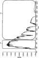
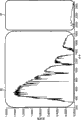
Fig. 4 a, Fig. 4 b and Fig. 4 c are the diagrams of the solar radiation of multiple solar cell and absorption spectra and the operation window that produced by condenser mirror of the present invention;
Fig. 5 a is the schematic plan with solar battery array of a plurality of goods of the present invention;
Fig. 5 b is the schematic cross sectional views of Fig. 5 a embodiment, and it has the optional protective layer shown in the dotted line;
Fig. 5 c is the schematic cross sectional views of Fig. 5 a that the alternate embodiment of the articles thermoformed therefrom around a plurality of solar cells is shown;
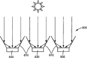
Fig. 6 is the schematic cross sectional views of articles thermoformed therefrom that the array of a plurality of Salar light-gathering speculums is shown;
Fig. 7 is the schematic diagram that is used for making the embodiment of the tracker that the linear compound parabolic concentrator assembly that is installed in frame moves;
Fig. 8 a is the schematic diagram of embodiment that the solar battery array in the band skylight that comprises Salar light-gathering speculum disclosed herein is shown, and wherein the orientation in this skylight is used to strengthen the capture to the sunray in morning;
Fig. 8 b is the schematic diagram of embodiment that the solar battery array in the band skylight that comprises Salar light-gathering speculum disclosed herein is shown, and wherein the orientation in this skylight is used to strengthen the capture to the sunray at noon; With
Fig. 8 c is the schematic diagram of embodiment that the solar battery array in the band skylight that comprises Salar light-gathering speculum disclosed herein is shown, and wherein the orientation in this skylight is used to strengthen the capture to the dusk sunray.
The specific embodiment
Fig. 1 shows goods 10 of the present invention.Goods 10 comprise multi-layer optical film 12 and suitable shape UV protective layer 14, and it is used as the Salar light-gathering speculum in application.Multi-layer optical film has optical stack, and described optical stack comprises a plurality of layer (not shown) that replace.The alternating layer of multi-layer optical film 12 comprises at least one birefringent polymer layer and at least one the second polymer layer.
Suitable shape UV protective layer 14 is applied to the surface of multi-layer optical film 12, can be used as the goods 10 that are used for light is gathered the Salar light-gathering speculum on the solar cell (not shown) with generation.Average light in goods 10 reflection of the gained whole wave-length coverage corresponding most of at least, and transmission or absorb the major part of the absorption bandwidth light outward of selected solar cell with the absorption bandwidth of selected solar cell.Also can adopt optional tack coat 16 and durable top coat 18 in the alternate embodiment of goods 10.
UV protective layer 14 (and thereby goods 10) is the adaptive material sheet normally.For the purposes of the present invention, term " suitable shape " is meant that goods 10 are stable on dimension, and make can be molded subsequently or be configured as various forms of flexible nature but have.Preferably, this suitable shape film has in UV protective layer 14 and is less than 10% film forming agent.Describe according to the present invention, film forming agent can be crosslinking agent or other multifunctional monomers.In most preferred embodiment, goods 10 can be thermoformed into different shape or structure at specific final application.
Fig. 2 shows the general application of goods 20 as the Salar light-gathering speculum.Goods 20 comprise multi-layer optical film 22 and the UV protective layer 24 that next-door neighbour's solar cell 26 is provided with.Goods 20 can receive the electromagnetic radiation 28 of the sun 30.The selection bandwidth 32 of electromagnetic radiation 28 is reflected on the solar cell 26.The non-desired bandwidth 34 of this electromagnetic radiation passes goods 20 and is not reflected on the solar cell 26.
Fig. 3 shows another general embodiment of goods of the present invention, and it is paraboloidal solar light-condensing speculum 40 forms.Electromagnetic radiation 42 polished object face Salar light-gathering speculums 40 from the sun 50 receive.Preferred bandwidth 48 is reflected on the solar cell 46, and the non-desired bandwidth 44 of electromagnetic radiation then passes paraboloidal solar light-condensing speculum 40 and is not reflected on the solar cell 46, thereby it may change the operating efficiency of solar cell potentially.Shape of products can comprise parabola or other curve forms, for example, and sinusoidal.
Multi-layer optical film
Conventional multi-layer optical film with alternating layer of at least a birefringent polymer and a kind of second polymer can be used for making goods of the present invention.The normally a plurality of polymeric layers that replace of multi-layer optical film, it is selected to realize the reflection to the specific bandwidth of electromagnetic radiation.
The material that is suitable for preparing at least one birefringent layers of disclosure multi-layer optical film comprises polymer (as, the copolyesters of polyester, copolyesters and modification).In this article, term " polymer " " will be interpreted as and comprise homopolymers and copolymer, and can by for example coetrusion or by the reaction that comprises ester exchange reaction form can miscible blend polymer or copolymer.Term " polymer " " and " copolymer " comprise random copolymer and block copolymer.Be applicable to according to the polyester in some exemplary multi-layer optical films of disclosure structure to generally include carboxylate subunit and glycol subunit, and can generate by the reaction of carboxylic acid ester monomer molecule and glycol monomer molecule.Each carboxylic acid ester monomer molecule has two or more carboxylic acids or ester functional group, and each glycol monomer molecule has two or more hydroxy functional groups.The carboxylic acid ester monomer molecule can be all identical, perhaps can be two or more dissimilar molecules.Glycol monomer molecule also is like this.Term " polyester " also comprises the Merlon derived from the reaction of glycol monomer molecule and carboxylate.
The suitable carboxylic acid ester monomer molecule that is used to form the carboxylate subunit of polyester layer comprises (for example) 2,6-naphthalenedicarboxylic acid and isomers thereof; Terephthalic acid (TPA); M-phthalic acid; Phthalic acid; Azelaic acid; Adipic acid; Decanedioic acid; The ENB dioctyl phthalate; The double-octane dioctyl phthalate; 1,4-cyclohexane cyclohexanedimethanodibasic and isomers thereof; Tert-butyl isophthalic acid, trimellitic acid, sodiosulfoisophthalic acid; 4,4 '-biphenyl dicarboxylic acid and isomers thereof; And these sour lower alkyl esters, for example methyl or ethyl ester.In this article, term " low alkyl group " is meant C1-C10 straight or branched alkyl.
The suitable glycol monomer molecule that is used to form the glycol subunit of polyester layer comprises ethylene glycol; Propane diols; 1,4-butanediol and isomers thereof; 1, the 6-hexylene glycol; Neopentyl glycol; The polyethylene glycol diethylene glycol (DEG); Three ring decanediols; 1,4-cyclohexanedimethanol and isomers thereof; The camphane glycol falls; Two ring ethohexadiols; Trimethylolpropane; Pentaerythrite; 1,4-benzene dimethanol and isomers thereof; Bisphenol-A; 1,8-dihydroxybiphenyl and isomers thereof; And 1, two (2-hydroxyl-oxethyl) benzene of 3-.
A kind of exemplary polymer that can be used as the birefringent layers in the multi-layer optical film of the present invention is PEN (PEN), and it can be made by the reaction of for example naphthalenedicarboxylic acid and ethylene glycol.Be selected as birefringent polymer under a lot of situations of poly-2,6 (ethylene naphthalate)s (PEN).PEN has big positive stress optical coefficient, can keep birefringence effectively after stretching, and seldom or not absorbs in visible-range.PEN also has big refractive index under isotropic state.When plane of polarization is parallel to about 1.64 to up to about 1.9 draw direction the time, its refractive index to the polarized incident light of 550nm wavelength increases.Increasing molecularly oriented can increase the birefringence of PEN.Molecularly oriented can be by keeping other stretching conditions fixedly to increase material extending to bigger draw ratio.PEN copolymer (CoPEN) (for example U.S. Patent No. 6,352,761 and U.S. Patent No. 6,449, those described in 093) is especially available, and the second more weak polymer co-extrusion compatibility is better because its low temperature process ability makes itself and heat endurance.Other semicrystalline polyesters that are suitable as birefringent polymer comprise (for example) poly-2,6 naphthalenedicarboxylic acid butanediol esters (PBN), PETG (PET) and copolymer thereof, for example U.S. Patent No. 6,449, those described in 093B2 or the U.S. Patent application No.20060084780.Perhaps, syndiotactic polystyrene (sPS) is another kind of available birefringent polymer.
Second polymer of multi-layer optical film can be by the glass transition temperature of the glass transition temperature and first birefringent polymer compatible and refractive index be similar to the various polymers of the isotropic refractive index of birefringent polymer.The example that is applicable to other polymer of blooming (particularly second polymer) comprises vinyl polymer and the copolymer that is made by the monomer such as vinyl naphthalene, styrene, maleic anhydride, acrylate and methacrylate.The example of this base polymer comprises polyacrylate, polymethacrylates (for example, gathering (methyl methacrylate) (PMMA)) and isotaxy or syndiotactic polystyrene.Other polymer comprise condensation polymer, for example polysulfones, polyamide, polyurethane, polyamic acid and polyimides.In addition, second polymer can be formed by the homopolymers of polyester, Merlon, fluoropolymer and dimethyl silicone polymer and copolymer and blend thereof.
Other exemplary suitable polymers (especially as second polymer) (for example comprise polymethyl methacrylate (PMMA), derive from the Ineos Acrylics (Wilmington of company with trade name CP71 and CP80, DE) those), or the homopolymers of polyethyl methacrylate (PEMA), wherein PEMA has the glass transition temperature lower than PMMA.Second polymer in addition comprises PMMA copolymer (coPMMA), the for example coPMMA that makes by 75 weight % methyl methacrylate (MMA) monomers and 25 weight % ethyl acrylate (EA) monomers (deriving from Ineos Acrylics company), the coPMMA that forms by MMA comonomer unit and n-BMA (nBMA) comonomer unit, or the blend of PMMA and polyvinylidene fluoride (PVDF) with trade name Perspex CP63.
Other suitable polymers (especially as second polymer) comprise polyolefin copolymer, for example with trade name Engage 8200 derive from Dupont Performance Elastomers ethylene-octene copolymer (PE-PO), derive from Fina Oil and Chemical company (Dallas, the copolymer of propylene-ethylene copolymers TX) (PPPE) and atactic polypropylene (aPP) and isotactic polypropylene (iPP) with trade name Z9470.Multi-layer optical film can also (for example) comprise functionalised polyolefin in the second polymer layer, for example linear low density maleic anhydride grafted polyethylene (LLDPE-g-MA) for example derives from E.I.duPont de Nemours﹠amp with trade name Bynel 4105; Co., Inc. (Wilmington, DE) those.
The preferred polymers batch mixing that is suitable for use as second polymer in the alternating layer with at least a birefringent polymer comprises PMMA, CoPMMA, dimethyl silicone polymer oxalyl amido chain segment copolymer (SPOX), fluoropolymer (comprise such as PVDF homopolymers and such as derived from tetrafluoroethene, the copolymer of those of hexafluoropropene and vinylidene fluoride (THV) and so on), the blend of PVDF/PMMA, acrylate copolymer, styrene, styrol copolymer, silicone copolymers, Merlon, Copolycarbonate, polycarbonate Alloys, the blend of Merlon and maleic anhydride of styrene and cyclic olefine copolymer.
The selection that is used to prepare the polymer composition of multi-layer optical film will be depended on the required bandwidth that will be reflected on the selected solar cell.Refractive index difference between the birefringent polymer and second polymer is big more, and the optical power that causes is big more, thereby allows bigger reflection bandwidth.Perhaps, can adopt extra play that bigger optical power is provided.The preferred compositions of birefringent layers and the second polymer layer can comprise (for example) following these: PET/THV, PET/SPOX, PEN/THV, PEN/SPOX, PEN/PMMA, PET/CoPMMA, PEN/CoPMMA, CoPEN/PMMA, CoPEN/SPOX, sPS/SPOX, sPS/THV, CoPEN/THV, PET/ fluoroelastomer, sPS/ fluoroelastomer and CoPEN/ fluoroelastomer.
In one embodiment, two or more multilayer optical mirror layers with different reflection bands of a spectrum lump together, to widen the reflection bands of a spectrum.For example, the PEN/PMMA multilayer mirror of the light of reflection 98% 400nm to 900nm is laminated to reflection 98% 900nm to 1800nm light the PEN/PMMA multilayer mirror and generate the broadband mirrors of the light of reflection 400nm to 1800nm.And for example, the PET/CoPMMA multilayer mirror of the light of reflection 97% 370nm to 750nm can be laminated to the multilayer mirror of light of the 700nm to 1350nm of reflection 97%, with the broadband mirrors of the light that generates reflection 370nm to 1350nm.
Multi-layer optical film prepares according to the process technology of routine, and for example US Patent No 6,783, those described in 349.Multi-layer optical film also can comprise non-optical protection boundary layer, for example, US Patent No 6,783, in 349 disclosed those.
Be used to multi-layer optical film to provide the desirable technique of controlled spectrum to comprise:
1) utilizes the axostylus axostyle heater control of the layer thickness value of coextrusion polymeric layer,, instructed among 349 people such as () Neavin as U.S. Patent No. 6,783.
2) in the timely layer thickness profile feedback of production period from layer thickness survey tool (for example, AFM (AFM), transmission electron microscope or SEM).
3) optical modeling is to generate required layer thickness profile.
4) carrying out the repetition axostylus axostyle based on the difference between survey layer characteristic pattern and the required layer characteristic pattern regulates.
The basic skills that is used for layer thickness profile control relates to based target layer thickness profile and the difference between the layer thickness profile surveyed and the axostylus axostyle zone is provided with power regulates.The increase of regulating the required axostylus axostyle power of layer thickness value in the given feedback areas at first can be calibrated with the heat input (watt) of each layer gained varied in thickness (nanometer) of generating in this heater area.Can use 24 axostylus axostyle zones that 275 layers are realized accurate spectrum control.After the calibration, in case the given target signature and the feature of surveying just can be calculated essential power adjusting.Repeating this process reaches an agreement until two features.
The layer thickness profile of this UV reflector (layer thickness value) can be adjusted to substantial linear and distribute, the light that (the thinnest) optical layers of winning is adjusted to 340nm has about 1/4 wavelength optical thickness (refractive index is taken advantage of physical thickness), and to the thickest layer development, the light that this final layer is adjustable as 420nm has the thick optical thickness of about 1/4 wavelength.
The UV protective layer
The UV protective layer is applied on the surface of multi-layer optical film, and the UV radiation of protecting multi-layer optical film not attended the meeting and cause deterioration.Sunshine (the especially ultraviolet radiation of 280nm to 400nm) can cause the deterioration of plastics, this so that cause change color and the mechanical performance variation.Suppressing the photooxidation deterioration is important for the open air application that needs long durability.PETG significantly increases when being lower than 320nm the absorption (for example, from about 360nm) of UV light, and very outstanding when being lower than 300nm.UV light in the PEN strong absorption 310-370nm scope absorbs afterbody and extends to about 410nm, and the absorption maximum appears at 352nm and 337nm place.The chain fracture occurs under the situation that has oxygen, and main photooxidation product is carbon monoxide, carbon dioxide and carboxylic acid.Except the direct photodissociation of ester group, also must consider oxidation reaction, it forms carbon dioxide equally via peroxide radical.
The UV protective layer can be by reflection UV light, absorb UV light, scattering UV light or its makes up and protects multi-layer optical film.Usually, the UV diaphragm can comprise any polymer composition that can stand the UV radiation in reflection, scattering or absorption UV radiation for a long time.The unrestricted example of this base polymer comprises PMMA, organosilicon thermoplastic, fluoropolymer and their copolymer and blend thereof.Exemplary UV protective layer comprises the PMMA/PVDF blend.
The plurality of optional additive can be added in the UV protective layer, to help the function of its protection multi-layer optical film.The unrestricted example of additive comprises that one or more are selected from the compound of ultra-violet absorber, hindered amine as light stabilizer, antioxidant and combination thereof.
UV stabilizing agent (for example, UV absorbent) is to intervene the physics of photic deterioration and the chemical compound of chemical process.Therefore, can stop UV light effectively, prevent polymer because UV radiation and photooxidation by the protective layer that use comprises the UV absorbent.With regard to purpose of the present invention, be red shift UV absorbent (RUVA) as the UV stabilizing agent of light stabilizer, its absorb at least 70% in 180nm to the 400nm wave-length coverage, preferred 80%, be preferably greater than 90% UV light especially.Suitable R UVA should very easily be dissolved in polymer, very easily absorbs, light is lasting and be heat-staple in 200 to 300 ℃ of temperature ranges, so that extrude processing to form protective layer.Most suitable RUVA also should be able to monomer copolymerization, form protective finish to handle by UV curing, gamma ray curing, electronic beam curing or heat cure.
RUVA has the spectrum coverage rate of increase in long wave UV zone, make it can stop the long wavelength UV light that can cause the polyester yellowing.Typical from 13 to 380 microns of UV protective layer thickness (0.5 to 15 mil), the RUVA loadings is 2-10%.The most effective a kind of RUVA is a benzotriazole cpd, and 5-trifluoromethyl-2-(2-hydroxy-3-alpha-cumyl--uncle's 5-octyl phenyl)-2H-BTA is (by Ciba Specialty Chemicals company (Tarryton NY) sells with trade name CGL-0139).Other preferred BTAs comprise 2-(2-hydroxyl-3,5-two-α-cumyl phenyl)-2H-BTA, 5-chloro-2-(the 2-hydroxyl-3-tert-butyl group-5-aminomethyl phenyl)-2H-BTA, 5-chloro-2-(2-hydroxyl-3,5-two-tert-butyl-phenyl)-2H-BTA, 2-(2-hydroxyl-3,5-two-tertiary pentyl phenyl)-2H-BTA, 2-(2-hydroxy-3-alpha-cumyl--uncle's 5-octyl phenyl)-2H-BTA, 2-(the 3-tert-butyl group-2-hydroxy-5-methyl base phenyl)-5-chloro-2H-BTA.Preferred RUVA in addition comprises 2 (4,6-diphenyl-1-3,5-triazine-2-yl)-own oxygen base-phenol of 5-.Other exemplary UV absorbents comprise with trade name Tinuvin 1577, Tinuvin 900 and Tinuvin 777 and derive from those of Ciba Specialty Chemicals company.In addition, the UV absorbent can be united use with hindered amine as light stabilizer (HALS) and antioxidant.Exemplary HALS comprises with trade name Chimassorb 944 and Tinuvin 123 and derives from those of Ciba Specialty Chemicals company.Exemplary antioxidant comprises with trade name Irganox 1010 and Ultranox 626 and derives from those of Ciba Specialty Chemicals company equally.
In alternate embodiment, suitable shape UV protective layer is the multi-layer optical film of the light of reflection about 350 to about 400nm (even more preferably from about 300nm to 400nm) wavelength.The polymer that is used to prepare multi-layer optical film does not preferably absorb the UV light in 300nm to the 400nm scope.Non-limitative example comprises PET/THV, PMMA/THV, PET/SPOX, PMMA/SPOX, sPS/THV, sPS/SPOX, has improved polyalkene copolymer (EVA), TPU/THV and the TPU/SPOX of THV.In a preferred embodiment, (Oakdale, 220 grades of Dyneon THV MN) and 2030 grades and PMMA one are used from the multilayer UV speculum of reflection 300-400nm, or are used from the multilayer mirror of reflection 350-400nm with PET one to derive from Dyneon LLC.Usually, 100 to 1000 layers combination of polymers is applicable to the present invention altogether.
Can comprise other additives in the UV protective layer.Non-pigmented particulate oxide zinc and titanium oxide also can be used as in the UV protective layer and stop or the scattering additive.For example, nano-scale particle can be scattered in polymer or the coating matrix, to reduce to UV radiation deterioration minimum.Nano-scale particle is transparent to visible light, scattering simultaneously or the harmful UV radiation of absorption, thus minimizing is to the infringement of thermoplastic.U.S. Patent No. 5,504,134 have described by using diameter in about 0.001 micron polymer substrate deterioration that the metal oxide particle of (more preferably about 0.01 micron to about 0.15 micrometer range) weakens to cause because of ultraviolet radiation to about 0.20 micrometer range.U.S. Patent No. 5,876,688 have instructed a kind of method for preparing micronized zinc oxide, when adding paint, coating, finish paint, plastic products, cosmetics etc. as UV blocking agent and/or scattering diluent, described micronized zinc oxide is enough little so that transparent, and it is suitable for using among the present invention very much.These can weaken the UV radiation the fine particle (for example, zinc oxide and titanium oxide) of granularity in the 10-100nm scope can from Kobo Products company (South Plainfield, NJ) commercially available.Fire retardant also can be used as additive and adds in the UV protective layer.
Except UV absorbent, HALS, nano-scale particle, fire retardant and antioxidant are added to the UV protective layer, UV absorbent, HALS, nano-scale particle, fire retardant and antioxidant can also be added to multilayer optical layer and optional durable top coat.Can also add fluorescence molecule and fluorescent whitening agent to UV protective layer, multilayer optical layer, optional durable top coat, or its combination.
The thickness of UV protective layer depends on the optical density target under the specific wavelength that is calculated by the Beers law.In certain embodiments, the optical density of UV protective layer at the 380nm place greater than 3.5,3.8 or 4; At the 390nm place greater than 1.7; At the 400nm place greater than 0.5.Persons of ordinary skill in the art will recognize that optical density should keep appropriateness constant in long goods length of life usually, so that the defencive function of expection is provided.
Can select UV protective layer and any optional additive to come in the Salar light-gathering speculum, to realize required defencive function, for example UV protection, property easy to clean and durability.Persons of ordinary skill in the art will recognize that the above-mentioned purpose that exists multiple means to realize the UV protective layer.For example, can add the additive that is soluble in very much in some polymer to composition.The persistence of additive in polymer particularly importantly.Additive should not make polymer deterioratoin or move out of polymer.In addition, layer thickness can change to realize required protection effect.For example, thicker UV protective layer will allow to realize that with low UVA concentration identical UV absorbs level, and will provide higher UVA persistence because of lower UVA migration driving force.A kind of mechanism that is used to detect change in physical properties is to use weathering circulation described in the ASTM G155 and the D65 light source of working under reflective-mode.Under described test; and when the UV protective layer is applied to goods; obviously ftracture, peel off in beginning, before layering or the muddiness; be no more than 5 in the b* value increase of using CIE L*a*b* space to obtain, be no more than 4, be no more than 3 or be no more than before 2; goods should stand under the 340nm at least 18,700kJ/m
2Expose to the open air.
Tack coat
Optionally tack coat can be between multi-layer optical film and UV protective layer, to help film to adhere to and long stability is provided when goods of the present invention are exposed to outdoor environment.The non-limitative example of tack coat comprises: SPOX and CoPET (comprising the modifier that for example uses the sulfonic acid functional group), PMMA/PVDF blend, by the alkene with the functionalized comonomer modification of maleic anhydride, acrylic acid, methacrylic acid and vinyl acetate.In addition, UV curing or heat cure acrylate, organosilicon, epoxy resin, siloxanes, urethane acrylate can be suitable as tack coat.Tack coat can contain above-mentioned UV absorbent alternatively.Tack coat can contain conventional plasticizer, tackifier or its combination alternatively.Tack coat can utilize conventional film technique to apply.
Optional top coat
Goods can comprise durable top coat alternatively, to help prevent the Salar light-gathering speculum because of being exposed to the outdoor environment premature deterioration.The common wear and shock-resistant of durable top coat, and the major function that can not hinder the electromagnetic radiation of the selected bandwidth of reflection.Durable top coat can comprise one or more in the following non-limitative example: PMMA/PVDF blend, thermoplastic polyurethane, curable polyurethane, CoPET, cyclic olefine copolymer (COC), fluoropolymer and copolymer thereof (for example, PVDF, ETFE, FEP and THV), thermoplasticity and curable acrylates, cross linked acrylic, crosslinked urethane acrylate, crosslinked carbamate, curable or crosslinked polyepoxides and SPOX.Also can adopt strippable polypropylene copolymer top layer.Perhaps, silanized silica colloidal sol copolymer hard conating can be used as durable top coat, to improve scratch resistance.Durable top coat can contain aforesaid UV absorbent, HALS and antioxidant.
Durable top coat provides mechanical endurance for goods.Some mechanism of measurement mechanical durability can be resistance to impact or wearability.The Taber wear test is a kind of test of wearability of definite film, and wearability is defined as the ability that material stands the mechanism such as mill is scraped or corrodes.According to ASTM D1044 method of testing, 500 gram loads are placed on the top of CS-10 abrasion wheel, and allow 50 weeks of rotation on 25.8 square centimeters of (4 square inches) test specimens.Measure before the Taber wear test and sample reflectivity afterwards, the result represents by reflectance varies %.For the purposes of the present invention, expectation reflectance varies % is less than 20%, preferably less than 10%, especially be more preferably less than 5%.
Other mechanical endurance that is fit to tests comprise break elongation, pencil hardness, sandblast test and the test of sieve sand milling consumption.Can with above-mentioned UVA and suitably the UV stabilizing agent add in the top coat, with at the bottom of being used for stable coatings and protecting group.The substrate that is coated with this type of durable hard conating is can be hot formed before at high temperature solidifying fully, then can by 80 ℃ down the back solidify and form durable hard conating in 15-30 minute.In addition, the silicone components that is used as durable top coat is hydrophobic in itself, can provide function of surface easy to clean to goods disclosed in this invention.
Because outdoor application, weathering also is the key character of Salar light-gathering speculum.Accelerated weathering research is a kind of option that proves that product properties is qualified.The common use of accelerated weathering research is similar to those technology described in the ASTM G-155 " standard operation (Standard practice for exposing non-metallic materials inaccelerated test devices that use laboratory light sources) that in the accelerated test device that uses the laboratory light source nonmetallic materials is exposed to the open air " and carries out on film.Described ASTM technology is regarded as the reasonable prediction factor of outdoor durable, that is, and correctly to the material property classification.
In alternate embodiment, can on a side of the multi-layer optical film opposite, adopt inversion structure with required UV protective layer.The application-specific that this alternative constructions can be goods provides additional functional character.For example, be desirably in the UV protective layer that provides additional on the multi-layer optical film, so that the back side protection to the UV radiation is provided.Other possible embodiment can comprise carbon black or IR absorbed layer on a side opposite with directly being exposed to sunlight.Another alternate embodiment can comprise ARC at dorsal part, to prevent dorsal part IR reflection.Tack coat (for example those disclosed) before this can be used to provide alternate embodiment.
When focusing on the solar cell as the Salar light-gathering speculum with the electromagnetic radiation with specific bandwidth, the gained physical characteristic of film provides the characteristic of enhancing.Protect membrane-bound multi-layer optical film can be designed in the electromagnetic radiation of the non-expectation of transmission, reflect the electromagnetic radiation of required bandwidth with the UV of selected thickness.Select multi-layer optical film to mate specific solar cell, the unique ability that reduces the radiation that is unfavorable for solar cell has simultaneously improved the operating efficiency of solar cell significantly.Some embodiment pairs of light corresponding with the absorption bandwidth of selected solar cell shows 98% or higher reflectivity.
The Salar light-gathering speculum can be close to the solar cell setting, to realize the reflection of the desired level on solar cell.Goods can be that stand alone type is used, perhaps can be administered in the substrate so that additional rigidity to be provided, or dimensional stability.The substrate that is fit to comprises (for example) sheet glass, polymer sheet and the polymer fiber composites that comprises glass fiber compound material.Optionally tack coat (for example previous described those) can be used for goods are adhered to substrate.In addition, can comprise the UV absorbent alternatively in the substrate.In another alternate embodiment, the goods thermoformable by solar concentrator routine shape or the size used.Hot forming is in U.S. Patent No. 6,788, has roughly among 463 people such as () Merrill and describes.In addition, the Salar light-gathering speculum can (for example) be strengthened by injection clad, gauffer or interpolation rib, foam interlayer or honeycomb, to improve its dimensional stability.A kind of exemplary reinforcement material is a double-walled polycarbonate sheet material, as deriving from Palram Americas company (Kutztown, sheet material PA) with SUNLITE MULTIWALL POLYCARB ONATE SHEET.In another embodiment, the Salar light-gathering mirror layer can be incorporated into infrared Absorption material, for example steel of the aluminium of japanning or japanning.In addition, the aluminium of japanning or steel can have ribs or strengthen structure, in order to improve dimensional stability.
Solar cell
The solar cell that is fit to comprises that those that go out with multiple developing material, described material respectively have and changes solar energy into electric unique absorption spectrum.All types of semi-conducting materials will have the characteristic band-gap energy, and described band-gap energy makes it absorb light most effectively under some wavelength of light, perhaps more precisely, and absorption of electromagnetic radiation on a part of solar spectrum.The example of material and the sunshine absorption band edge wavelength thereof that are used to make solar cell include, but is not limited to: crystalline silicon unijunction (about 400nm is to about 1150nm), non-crystalline silicon unijunction (about 300nm is to about 720nm), banded silicon (about 350nm is about 1150nm extremely), CIGS (CIGS) (about 350nm is about 1100nm extremely), CdTe (about 400nm is about 895nm extremely), GaAs tie (about 350nm is about 1750nm extremely) more.The absorption band edge, a shorter wavelength left side of these semi-conducting materials is usually between 300nm and 400nm.It will be understood by those skilled in the art that and develop new material being used to have the solar cell more efficiently at its own unique longer wavelength absorption band edge, and laminated reflective film will have corresponding zone of reflections edge.
Fig. 4 a, Fig. 4 b and Fig. 4 c show may using of the goods of the present invention that combine with specific solar cell.Fig. 4 a is the curve map of solar spectrum to the absorption of crystalline silicon unijunction solar cell.Fig. 4 a shows and the visible light and the corresponding operation window 60 of reflection of the near-infrared electromagnetic radiation of high about 1150nm.Far-infrared band 62 greater than about 1150nm is not reflected.Use another example of non-crystalline silicon unijunction to be illustrated among Fig. 4 b.In Fig. 4 b, the operation window 70 of goods of the present invention is corresponding with longer wavelength (infrared) the absorption band edge of non-crystalline silicon unijunction solar cell.Infrared region 72 is not reflected by goods of the present invention.Fig. 4 c shows the application with the condenser mirror of the GaAs multijunction solar cell at the longer wavelength with about 1750nm (infrared) absorption band edge.In Fig. 4 c, operation window 80 is corresponding to the electromagnetic radiation of goods reflection of the present invention.Infra-red radiation 82 is not reflected by condenser mirror.
Shown in Fig. 4 a, Fig. 4 b and Fig. 4 c, when the selected solar cell of next-door neighbour is placed, condenser mirror be used for with the corresponding whole wave-length coverage of the absorption bandwidth of solar cell in the major part at least of average light reflex to solar cell.Condenser mirror can not reflex to the major part of the light outside the absorption bandwidth of solar cell on the solar cell.The major part of the average light in the corresponding whole wave-length coverage of absorption bandwidth that reflected by goods and solar cell represent to be selected from greater than 50% (as, greater than 70%, greater than 80%, greater than 90% or even greater than 95%) value.In certain embodiments, goods show 98% or higher reflectivity to the pairing light of absorption bandwidth of selected solar cell.Electromagnetic radiation outside the absorption bandwidth of solar cell is by condenser mirror transmission or absorption.With light in the corresponding whole wave-length coverage of the absorption bandwidth of solar cell by greater than 1 (as, at least 1.5,2,3,5,10,20, greater than 50 or greater than 100 as many as about 800 or 1000) amount gathered on the solar cell.For example, light can gather on the solar cell by 1.1 amounts to about 5 scopes.The condenser mirror that combines with the crystalline silicon single junction cell will reflect about 400nm usually to about 1150 or the light of 1200nm, greater than 1150 or the major part at least of the light of 1200nm be not reflected.The condenser mirror that combines with the GaAs multijunction cell will reflect about 350nm usually to the light of about 1750nm, not be reflected greater than the major part at least of the light of 1750nm.The condenser mirror that combines with the non-crystalline silicon single junction cell will reflect about 300nm usually to the light of about 720nm, not be reflected greater than the major part at least of the light of 720nm.The condenser mirror that combines with banded silion cell will reflect about 400nm usually to the light of about 1150nm, not be reflected greater than the major part at least of the light of 1150nm.The condenser mirror that combines with the CIGS battery will reflect about 350nm usually to the light of about 1100nm, not be reflected greater than the major part at least of the light of 1100nm.The condenser mirror that combines with the cadmium telluride battery will reflect about 400nm usually to the light of about 895nm, not be reflected greater than the major part at least of the light of 895nm.In some embodiment of any condenser mirror disclosed herein, the infrared light that is not reflected is by transmission.
Condenser mirror of the present invention is because following former thereby can improve the efficient of solar cell: (i) significantly reduce non-selection bandwidth, thereby in fact solar cell overheated reduced to minimum; (ii) the power that obtains to increase by the polymer speculum is exported, thereby realizes low cost/output energy ($/Watt); And (iii) increase durability owing to UV protection and wearability.
When anti-reflecting surface structured film or coating are applied to the front surface of the solar cell that combines with solar collecting device disclosed herein, can realize the further enhancing of solar cell power output.Surface texture in film or the coating changes the incidence angle of light usually, makes it surpass critical angle and enters polymer and solar cell and by internal reflection, cause by the more absorptions of solar cell.This type of surface texture can be the shape of (for example) linear prism, pyramid, awl or column structure.For prism, the drift angle of prism usually less than 90 the degree (as, less than 60 the degree).The refractive index of surface structuration film or coating usually less than 1.55 (as, less than 1.50).By using stable and the hydrophobic or hydrophilic material of intrinsic UV, can make these anti-reflecting surface structured film or coating durable and easy to clean.Can improve durability by adding inorganic nano-particle.
Fig. 5 a, Fig. 5 b and Fig. 5 c show the application of condenser mirror and solar battery array.In Fig. 5 a, solar cell 84 is placed in the array 92 with a plurality of condenser mirrors 86, the setting of described condenser mirror next-door neighbour solar cell reflexes on the solar cell with the major part at least of the average light in the whole wave-length coverage that will be corresponding with the absorption bandwidth of solar cell.The outer light of required bandwidth can not reflected by condenser mirror.In Fig. 5 b, show the array of solar cell 84 and condenser mirror 86 and optionally ultraviolet reflection mirror 88 and optionally infrared reflection mirror 90 with schematic cross sectional views.Fig. 5 c shows the alternate embodiment of condenser mirror 86 thermosetting around solar cell 84.In this embodiment, condenser mirror 86 is from the side and the backside reflection of solar cell 84, with the efficient of further raising system.
Persons of ordinary skill in the art will recognize that Salar light-gathering speculum of the present invention can various arrangements and array combine application with solar cell.Fig. 6 is the Salar light-gathering speculum 94 that comprises the array of a plurality of curved reflectors 96, and described curved reflector comprises the continuous multilayer speculum 98 that is laminated to continuous UV protective layer 102, and it gathers sunshine on the solar cell 100.
Salar light-gathering speculum with the solar cell combination can further be used with other conventional solar collecting devices, with the application of further raising Salar light-gathering speculum.For example, can use heat transfer unit (HTU) with from the solar cell harvest energy or from solar cell dissipation heat.Conventional radiator comprises the Heat Conduction Material that comprises rib, pin or fin, the surface area that is used to conduct heat with increase.Heat Conduction Material comprises by filler modified metal or polymer with the thermal conductivity of improving polymer.Heat-conductive bonding agent (as, derive from the heat-conductive bonding agent of 3M company with trade name 3M TC-2810) can be used to solar cell is attached to heat transfer unit (HTU).In addition, conventional heat-transfer fluid (for example water, oil or Fluorinert heat-transfer fluid) can be used as heat transfer unit (HTU).
In certain embodiments, the solar battery array that combines with condenser mirror can be arranged on the conventional celestial body tracking means.For example, in some embodiment of solar collecting device disclosed herein, in the two at least one of one or more solar cells or at least one Salar light-gathering speculum is connected to one or more celestial body followers (promptly, one or more solar cells are connected to one or more celestial body followers, at least one Salar light-gathering speculum is connected to one or more celestial body followers, and perhaps one or more solar cells and at least one Salar light-gathering speculum all are connected to one or more celestial body followers).Described one or more solar cell or at least one Salar light-gathering speculum or its both can the pivot mode being installed on the frame.In certain embodiments, one or more solar cells or at least one Salar light-gathering speculum are all can the pivot mode being installed on the frame.With the mode mounted component that can pivot can (for example) in a direction or on both direction, pivot.In certain embodiments, one or more solar cells are static.
An embodiment of solar collecting device who comprises the celestial body follower is shown in Figure 7.Fig. 7 shows solar collecting device 700, and it comprises the Salar light-gathering speculum that forms groove 710, and solar cell 730 is arranged on the axle.Two bars 770 that extend outside the end piece 712 of groove 710 are used in each end of assembly groove is connected respectively to frame 720 and cross bar 722.Cross bar 722 can be connected to driving mechanism.By a plurality of grooves 710 are arranged in the pair of parallel stationary gantry pivotly, as shown in Figure 7, in certain embodiments, each groove 710 attached cross bar 722 can make all grooves around its pivot simultaneously.Therefore, the orientation of all grooves 710 can jointly be regulated as one man to follow the sun.Although Fig. 7 shows two cross bars 722, on groove 710 each side each one, can also only use a cross bar.In some embodiment of solar collecting device 700 shown in Figure 7, groove 710 aligns on east-west direction, rotary freedom is not less than 10 degree, 15 degree, 20 degree or 25 degree usually, for example be used for regulating to follow the tracks of the sun with seasonal variations (that is, by the different tracks between equinox and the solstices).When solar cell 730 was packed in the linear compound parabolic concentrator groove 710 of south dip, incident solar energy irradiation entered in the acceptance angle of compound parabolic concentrator.Paraboloidal hole determine how long the position of groove 710 must change once (as, per hour change number of times, change the change number of times of number of times or lower frequency every day).In some embodiment of solar collecting device 700 shown in Figure 7, solar cell aligns on North and South direction, and rotary freedom is not less than 90 degree, 120 degree, 160 degree or 180 degree usually, for example is used for whole day and regulates to follow the sun along with the sun moves forward into line trace on whole sky.In some of these embodiment, frame can be installed to the backboard (not shown) of (for example) solar collecting device, and this backboard can comprise the mechanism that is used to regulate inclination, to follow the tracks of the sun with seasonal variations.Although groove shown in Figure 7 710 has parabolic shape, also can use other shapes (as, hyperboloid, ellipse, tubulose or triangle).Allow Salar light-gathering speculum and/or solar cell in U.S. Patent Application Publication No.2007/0251569 people such as () Shan, to describe to some extent at the other celestial body follower that pivots on the both direction and can be used for solar collecting device disclosed herein.
Another embodiment of solar collecting device that comprises the celestial body follower is shown in Fig. 8 a, Fig. 8 b and Fig. 8 c.In this embodiment, array 800 comprises solar cell 830 and skylight 810, according to the contiguous solar cell of the Salar light-gathering speculum of any embodiment disclosed herein can the pivot mode installing.The skylight can comprise (for example) be applied to substrate (as, sheet glass, polymer sheet, comprise the metal of structuring polymer sheet, polymer fiber composites or the japanning of undulating horizon compound or multiwall polymer sheet structure) on Salar light-gathering speculum disclosed herein or self-supporting speculum.In certain embodiments, the skylight comprises and is laminated to polymer sheet (as, Salar light-gathering speculum disclosed herein PMMA).The skylight can directly be attached to solar cell either side (as, pass through hinge), shown in Fig. 8 a, Fig. 8 b or Fig. 8 c, perhaps the skylight can be can the pivot mode being installed on the frame that also keeps solar cell.In certain embodiments, two skylights link to each other with each solar cell (as, hinged each solar cell).
In Fig. 8 a, Fig. 8 b and Fig. 8 c, skylight 810 is respectively towards morning, noon and the orientation of the sun at dusk.The sun is followed the tracks of in skylight 810, and makes solar cell 830 can catch more daylight 828.Therefore, in array 800, need less photovoltaic cell 830 usually.Array 800 shown in Fig. 8 a and Fig. 8 c can be effective especially aspect catching at the daylight that increases morning and dusk.The skylight can be moved independently, and rotary freedom is not less than 90 degree, 120 degree, 160 degree or 180 degree usually, and (for example) regulates to follow the sun along with it moves forward into line trace on whole sky to be used for whole day.Alternatively, array 800 can be installed to (for example) one or more backboard (not shown), and described backboard can comprise and is used to regulate inclination to follow the tracks of the mechanism of the sun with seasonal variations.The shape in skylight can be the plane, general plane or crooked.
In certain embodiments, have low concentration ratio when skylight 810 comprises (as, less than 10, maximum 5, maximum 3, maximum 2.5 or 1.1 to about 5 scopes) IR Transflective mirror the time, can reduce the needs of expensive heavy photovoltaic cell heat management device.Can regulate the Salar light-gathering degree with respect to the size and the speculum of photovoltaic cell with respect to the angle of photovoltaic cell by (for example) speculum, to optimize the Salar light-gathering rate in required geographical position.In addition, can use closed-loop control system to regulate a day window position, so that concentration ratio is minimized, so that photovoltaic cell maintains below 85 ℃.
The moving of skylight 810 shown in groove 710 shown in Figure 7 or Fig. 8 a, Fig. 8 b and Fig. 8 c can pass through various mechanism (as, piston actuated bar, screw drive bar or gear, belt pulley drive cable and camming) control.Software can also be integrated based on gps coordinate and follower, to optimize the position of speculum.
Example
Comparative example 1
Prepare multi-layer optical film with first optical layers and second optical layers, described first optical layers is by (the St.Paul of 3M company, MN) Zhi Bei PEN (PEN) makes, (Philadelphia, PA) polymethyl methacrylate of selling with trade name VO44 Acrylic Resin (PMMA) makes described second optical layers by Arkema company.By multiple layer polymer fusion manifold coextrusion PEN and PMMA, has the multilayered molten stream of 530 first and second optical layers that replace with generation.Except first and second optical layers, a pair of non-optical layers that also is made of PEN is that optical layers stacks the protection top layer on the either side by coextrusion.Should be poured on the chill casting roller for 22 meters with per minute by multi-layer co-extruded melt-flow, produce about 1075 microns (43 mil) thick multilayer casting tablet.Then, this multilayer casting tablet is heated 10 seconds, the draw ratio of biaxial orientation to 3.8 * 3.8 then in 145 ℃ tentering baking oven.The multilayer film of orientation further is heated to 225 ℃ of 10 second, to increase the degree of crystallinity of PEN layer.(derive from the reflectivity that the visible mirror coating of this multilayer is measured by Perkin-Elmer company (Waltham, MA)), average reflectance is 98.5% on the 390-850nm bandwidth with LAMBDA 950 spectrophotometers.Be exposed to the xenon arc lamp aging testing instrument according to ASTMG155-05a after 3000 hours, the b* that records 5 units with LAMBDA 950 spectrophotometers changes.
Example 1
Use PEN and the PMMA material identical, prepare multi-layer optical film by the birefringent layers that makes by PEN with by the second polymer layer that PMMA makes with comparative example 1.By multiple layer polymer fusion manifold coextrusion PEN and PMMA, has the multilayered molten stream of 275 birefringent layers that replace and the second polymer layer with generation.In addition, a pair of non-optical layers that also is made of PEN is that optical layers stacks the protection top layer on the either side by coextrusion.Should be poured on the chill casting roller for 22 meters with per minute by multi-layer co-extruded melt-flow, produce about 725 microns (29 mil) thick multilayer casting tablet.Then, multilayer is cast tablet heats 10 seconds, the draw ratio of biaxial orientation to 3.8 * 3.8 then in 145 ℃ tentering baking oven.The multilayer film of orientation further is heated to 225 ℃ of 10 second, to increase the degree of crystallinity of PEN layer.With the reflectivity of the visible mirror coating of this multilayer of LAMBDA 950 spectrophotometer measurements, the average reflectance on the 400-1000nm bandwidth is 98.5%.PMMA (VO44) derives from (Philadelphia of Arkema company, PA), the UV absorbent that obtains with trade name TINUVIN 1577 of itself and 5 weight % and the hindered amine as light stabilizer that obtains with trade name CHIMASSORB 944 of 0.15 weight % (all derive from the CIBASpecialty Chemicals (Tarryton of company, NY)) extrude compound (PMMA-UVA/HALS), PMMA-UVA/HALS that obtains and adhesive tie layer are (by duPont de Nemours ﹠amp; Co., Inc. (Wilmington, DE) sell with trade name BYNEL E418) be applied on the multilayer mirror film that makes as mentioned above by coextrusion, under pressure, be directed into roll gap with the teeming line speed of 0.38 meter per second (75 feet per minutes) under 32 ℃ of (90) temperature simultaneously to cast instrument 893kg/m (50 pounds of every linear inches) with mirror finished surface.The layer of coextrusion coating has the gross thickness of 254 microns (10 mils), and adhesive layer thickness ratio in top layer is 20: 1.Same material is applied on the apparent surface of the visible mirror coating of multilayer by coextrusion.The UV absorption band edge of this extruding coating has 50% transmissivity at the 410nm place, has 3.45 absorbance at the 380nm place.Be exposed to the xenon arc lamp aging testing instrument after 3000 hours according to ASTM G155-05a, recording b* and change less than 1.0.
Example 2
Multilayer mirror can (St.Pau, the second polymer layer that polyoxamide organosilicon (SPOX) MN) makes prepares with the birefringent layers that is made by PEN with by deriving from 3M company.By multiple layer polymer fusion manifold coextrusion PEN and SPOX layer, has the multilayered molten stream of 550 first and second optical layers that replace with generation.Except birefringent layers and the second polymer layer, a pair of non-optical layers that also is made of PEN can be that optical layers stacks the protection top layer on the either side by coextrusion.This multi-layer co-extruded melt-flow can be poured on the chill casting roller for 22 meters with per minute, produce about 1400 microns (55 mil) thick multilayer casting tablet.Then, the tablet of multilayer can being cast heats 10 seconds, the draw ratio of biaxial orientation to 3.8 * 3.8 then in 145 ℃ tentering baking oven.The multilayer film of orientation further can be heated to 225 ℃ of 10 second, to increase the degree of crystallinity of PEN layer.The reflectivity of the visible mirror coating of available this multilayer of LAMBDA 950 spectrophotometer measurements, expectation has 98.9% average reflectance on the 390-1750nm bandwidth.PMMA-UVA/HALS (its can as preparation as described in the example 1) coextrusion can be applied on the multilayer mirror film that makes as mentioned above, under pressure, it guided into roll gap with the teeming line speed of 0.38 meter per second (75 feet per minutes) under 32 ℃ of (90 times) temperature simultaneously cast instrument 893kg/m (50 pounds of every linear inches) with mirror finished surface.The layer of coextrusion coating will have the gross thickness of 254 microns (10 mils), and adhesive layer thickness ratio in top layer is 20: 1.Same material can be applied on the apparent surface of the visible mirror coating of multilayer by coextrusion.The UV absorption band edge of estimating this extruding coating has 50% transmissivity at the 410nm place, has 3.45 absorbance at the 380nm place.Be exposed to the xenon arc lamp aging testing instrument after 3000 hours according to ASTM G155-05a, expection b* changes less than 2.0.
Example 3
Can prepare multilayer mirror with birefringent layers that makes by PET and the second polymer layer that makes by SPOX (all deriving from 3M company).Can pass through multiple layer polymer fusion manifold coextrusion PEN and SPOX, have the multilayered molten stream of 550 birefringent layers that replace and the second polymer layer with generation.In addition, a pair of non-optical layers that also is made of PEN can be that optical layers stacks the protection top layer on the either side by coextrusion.This multi-layer co-extruded melt-flow can be poured on the chill casting roller for 22 meters with per minute, produce about 1400 microns (55 mil) thick multilayer casting tablet.Then, the tablet of multilayer can being cast heats 10 seconds, the draw ratio of biaxial orientation to 3.8 * 3.8 then in 95 ℃ tentering baking oven.The multilayer film of orientation further can be heated to 225 ℃ of 10 second, to increase the degree of crystallinity of PEN layer.The reflectivity of the visible mirror coating of available this multilayer of LAMBDA 950 spectrophotometer measurements, expectation has 98.4% average reflectance on the bandwidth of 390-1200nm.PMMA-UVA/HALS composition (can as preparation as described in the example 1) and adhesive tie layer (as described in example 1) coextrusion can be applied on the multilayer mirror film that makes as mentioned above, under pressure, it guided into roll gap with the teeming line speed of 0.38 meter per second (75 feet per minutes) under 32 ℃ of (90) temperature simultaneously cast instrument 893kg/m (50 pounds of every linear inches) with mirror finished surface.The layer of coextrusion coating will have the gross thickness of 254 microns (10 mils), and adhesive layer thickness ratio in top layer is 20: 1.Same material can be applied on the apparent surface of the visible mirror coating of multilayer by coextrusion.The UV absorption band edge of estimating this extruding coating has 50% transmissivity at the 410nm place, has 3.45 absorbance at the 380nm place.Be exposed to the xenon arc lamp aging testing instrument after 3000 hours according to ASTM G155, expection does not have b* to change.
Example 4
Can (derive from the second polymer layer that Dyneon LLC (Oakdale, MN)) makes with trade name THV2030 and prepare multilayer mirror with the birefringent layers that makes by PEN with by fluoropolymer.Can pass through multiple layer polymer fusion manifold coextrusion PEN and fluoropolymer, have the multilayered molten stream of 550 first birefringent layers that replace and the second polymer layer with generation.Except birefringent layers and the second polymer layer, a pair of non-optical layers that also is made of PEN can be that optical layers stacks the protection top layer on the either side by coextrusion.This multi-layer co-extruded melt-flow can be poured on the chill casting roller for 22 meters with per minute, produce about 1400 microns (55 mil) thick multilayer casting tablet.Then, the tablet of multilayer can being cast heats 10 seconds, the draw ratio of biaxial orientation to 3.8 * 3.8 then in 145 ℃ tentering baking oven.The multilayer film of orientation further can be heated to 225 ℃ of 10 second, to increase the degree of crystallinity of PEN layer.The reflectivity of the visible mirror coating of available this multilayer of LAMBDA 950 spectrophotometer measurements, expectation has 99.5% average reflectance on the bandwidth of 390-1750nm.PMMA-UVA/HALS composition (can as preparation as described in the example 1) and adhesive tie layer (as described in example 1) coextrusion can be applied on the multilayer mirror film that makes as mentioned above, under pressure, it guided into roll gap with the teeming line speed of 0.38 meter per second (75 feet per minutes) under 32 ℃ of (90) temperature simultaneously cast instrument 893kg/m (50 pounds of every linear inches) with mirror finished surface.The layer of coextrusion coating will have the gross thickness of 254 microns (10 mils), and adhesive layer thickness ratio in top layer is 20: 1.Same material can be applied on the apparent surface of the visible mirror coating of multilayer by coextrusion.The UV absorption band edge of estimating this extruding coating has 50% transmissivity at the 410nm place, has 3.45 absorbance at the 380nm place.Be exposed to the xenon arc lamp aging testing instrument after 3000 hours according to ASTM G155, the b* that records expection changes less than 2.0.
Example 5
Can prepare multilayer mirror with birefringent polymer layer that makes by PET and the second polymer layer that makes by fluoropolymer (deriving from the THV2030 of Dyneon LLC).Can pass through multiple layer polymer fusion manifold coextrusion PEN and fluoropolymer, have the multilayered molten stream of 550 first and second polymeric layers that replace with generation.Except birefringent layers and the second polymer layer, a pair of non-optical layers that also is made of PEN can be that optical layers stacks the protection top layer on the either side by coextrusion.This multi-layer co-extruded melt-flow can be poured on the chill casting roller for 22 meters with per minute, produce about 1400 microns (55 mil) thick multilayer casting tablet.Then, the tablet of multilayer can being cast heats 10 seconds, the draw ratio of biaxial orientation to 3.8 * 3.8 then in 95 ℃ tentering baking oven.The multilayer film of orientation further can be heated to 225 ℃ of 10 second, to increase the degree of crystallinity of PEN layer.The reflectivity of the visible mirror coating of available this multilayer of LAMBDA 950 spectrophotometer measurements, expectation has 99% average reflectance on the bandwidth of 390-1200nm.PMMA-UVA/HALS composition (as preparation as described in the example 1) and adhesive tie layer (as preparation as described in the example 1) coextrusion can be applied on the multilayer mirror film that makes as mentioned above, under pressure, it guided into roll gap with the teeming line speed of 0.38 meter per second (75 feet per minutes) under 32 ℃ of (90) temperature simultaneously cast instrument 893kg/m (50 pounds of every linear inches) with mirror finished surface.The layer of coextrusion coating will have the gross thickness of 254 microns (10 mils), and adhesive layer thickness ratio in top layer is 20: 1.Same material can be applied on the apparent surface of the visible mirror coating of multilayer by coextrusion.The UV absorption band edge of estimating this extruding coating has 50% transmissivity at the 410nm place, has 3.45 absorbance at the 380nm place.Be exposed to the xenon arc lamp aging testing instrument after 3000 hours according to ASTM G155, expection does not have b* to change.
Example 6
Can with derive from goods of any one among the example 2-5 be laminated to the multilayer UV speculum that makes with UV transparent polymer (for example PMMA and THV) or with its coextrusion.This multilayer UV speculum can prepare with first optical layers that is made by PMMA and the second polymer layer that is made by fluoropolymer THV2030.Can pass through multiple layer polymer fusion manifold coextrusion PMMA and fluoropolymer THV2030, have the multilayered molten stream of 150 first and second polymeric layers that replace with generation.In addition, a pair of non-optical layers that also is made of PMMA can be that optical layers stacks the protection top layer on the either side by coextrusion.These PMMA top layers can be extruded compound with the absorbent (buying with trade name TINUVIN 405) of 2 weight %.This multi-layer co-extruded melt-flow can be poured on the chill casting roller for 22 meters with per minute, produce about 300 microns (12 mil) thick multilayer casting tablet.Then, multilayer is cast tablet heats 10 seconds, the draw ratio of biaxial orientation to 3.8 * 3.8 then in 135 ℃ tentering baking oven.The reflectivity of the visible mirror coating of available this multilayer of LAMBDA 950 spectrophotometer measurements, expectation has 95% average reflectance on the bandwidth of 350-420nm.
Example 7
Can be in addition (for example with the heat cure siloxanes, derive from California Hardcoat company (Chula Vista, the methyl polysiloxane polymer of filling silica CA)) coating as any one described durable speculum among the example 2-6 with trade name PERMA-NEW 6000.At the bottom of described heat cure siloxanes can be coated to acrylic with the Meyer rod, the about 3.5-6.5 micron of coating thickness.Coating can at first at room temperature air-dry several minutes, further solidifying 15-30 minute in conventional baking oven under 80 ℃ then.Can consume the heat cure coated sample of testing gained by the sieve sand milling.After 60 minutes, can measure the turbidity of sample by sieve sand milling consumption with silica sand at sample.Expected results will show the turbidity that is low to moderate less than 1%.Record with the Taber wear test, the durable top coat of this form will have usually than PMMA better wear-resisting/scratch resistance.
Example 8
Will be as example 1 described durable Salar light-gathering speculum 204 ℃ (400) following preheating 35 seconds, vacuum-thermoform is the parabolic casting mold with 10.16cm (4 inches) diameter of 15.24cm (6 inches) radius of curvature then.This hot formed durable speculum is a rigidity, and keeps hot formed shape under 85 ℃.This parabolic multilayer speculum can gather the solar radiation greater than 100 times on the high-efficiency three-joint GaAs photovoltaic cell.
Example 9
To be attached to the polysilicon photovoltaic module of buying with trade name SHARP 80W as example 1 described durable speculum, this module and shown in Figure 2 quite.Durable speculum has the size identical with solar cell (identical surface area), and becomes 55 degree angles attached with the surface of solar module.When vertical plane to the solar time, compare with the situation that does not have attached durable speculum, solar cell has produced many 65% power, and compares with the situation that does not have durable speculum solar concentrator, and the temperature that records at the dorsal part of solar cell raises less than 10 ℃.Become 30 degree angles with the surface of solar cell at the sun, and a durable speculum also becomes 30 degree angles with the surface of solar cell, and another durable speculum is parallel under the situation of surface modulation of solar cell, compare with the situation that does not have attached durable speculum, solar cell has produced many 95% power, and compare with the situation that does not have durable mirror concentrator, the temperature that records at the dorsal part of solar cell raises less than 15 ℃.
Example 10
The visible mirror coating of example 1 is laminated into and derives from the 0.63cm of Arkema company with trade name PLEXIGLAS VO44 (the PMMA sheet that 0.25 ") is thick; described PMMA sheet is attached to the side of 80 watts of crystalline silicon photovoltaic modules (buying with trade name SHARP 80W) with extra hinge, described hinge allow shown in Fig. 8 a-c the sun to be followed the tracks of.
Photovoltaic module power output is measured with hand-held voltage/current meter, and by open-circuit voltage be multiply by closed loop current, and then multiply by 0.75 activity coefficient and calculate, and prerequisite supposes that activity coefficient is not changed by condenser mirror.By a plurality of thermocouples are adhered to PV module dorsal part with adhesive tape, use infrared pyrometer to carry out temperature survey simultaneously.Autumn in 2008 was carried out power measurement some days at the Si Kandiya of Minn. (at north latitude and have temperate climate).Any cloud or mist appear in the air in the same day, and so carry out the mean time of data, observe sizable fluctuation.Also on the contrast photovoltaic module of attached condenser mirror not, carried out power measurement.Power measurement the results are shown in the following table 1.The temperature of photovoltaic module is not above 85 ℃.
Table 1

* suppose that activity coefficient is 0.75
Example 11
Film 1
Prepare UV-VIS reflection multi-layer optical film with first optical layers and second optical layers, described first optical layers is by derive from Eastman Chemical (Kingsport with EASTAPAK 7452, TN) PETG (PET1) makes, (derive from Ineos Acrylics company (Memphis, TN)) with PERSPEX CP63 (CoPMMA1) makes described second optical layers by the methyl methacrylate of 75 weight % and the ethyl acrylate of 25 weight %.By multiple layer polymer fusion manifold with PET1 and CoPMMA1 coextrusion, to form stacking of 550 optical layers.The layer thickness profile of this UV reflector (layer thickness value) is adjusted to the substantial linear profile, wherein first (the thinnest) optical layers is adjusted to 370nm light is had about 1/4 wavelength optical thickness (refractive index is taken advantage of physical thickness) and to thickest layer development, described thickest layer is conditioned has the thick optical thickness of about 1/4 wavelength to 800nm light.The layer thickness profile of regulating this type of film by the axostylus axostyle equipment that uses instruction in the U.S. Patent No. 6,783,349 people such as () Neavin in conjunction with the layer profile information that obtains with microscopy, thereby improved spectral characteristic.
Except these optical layers, the non-optical protection top layer of PET1 (each 260 micron thickness) by coextrusion on the optical stack either side.Should be poured on the chill casting roller for 5.4 meters with per minute by multi-layer co-extruded melt-flow, produce about 1100 microns (43.9 mil) thick multilayer casting tablet.Then multilayer is cast tablet 95 ℃ of following preheating about 10 seconds, and with 3.3: 1 draw ratio uniaxial orientation in the vertical.The tablet of then multilayer being cast heated for 10 seconds in 95 ℃ tentering baking oven, then uniaxial orientation to 3.5 in the horizontal: 1 draw ratio.The multilayer film of orientation was further heated for 10 seconds down at 225 ℃, to increase the degree of crystallinity of PEN1 layer.(deriving from Perkin-Elmer company (Waltham, LAMBDA 950 UV/VIS/NIRSPECTROPHOTOMETER MA)) records UV reflection multi-layer optical film (film 1) have 96.8% average reflectance on the 370-800nm bandwidth with spectrophotometer.
Film 2
Use first optical layers that makes by PET1 and prepare the near-infrared reflection multi-layer optical film by second optical layers that CoPMMA1 makes.By multiple layer polymer fusion manifold with PET1 and CoPMMA1 coextrusion, to form stacking of 550 optical layers.The layer thickness profile of this near-infrared reflection device (layer thickness value) is adjusted to the substantial linear profile, wherein first (the thinnest) optical layers is adjusted to 750nm light is had about 1/4 wavelength optical thickness (refractive index is taken advantage of physical thickness) and to thickest layer development, described thickest layer is conditioned has the thick optical thickness of about 1/4 wavelength to 1350nm light.The layer thickness profile of regulating this type of film by the axostylus axostyle equipment that uses instruction in the U.S. Patent No. 6,783,349 people such as () Neavin in conjunction with the layer profile information that obtains with microscopy, thereby improved spectral characteristic.
Except these optical layers, the non-optical protection top layer of PET1 (each 260 micron thickness) by coextrusion on the optical stack either side.Should be poured on the chill casting roller for 3.23 meters with per minute by multi-layer co-extruded melt-flow, produce about 1800 microns (73 mil) thick multilayer casting tablet.Then multilayer is cast tablet 95 ℃ of following preheating about 10 seconds, and with 3.3: 1 draw ratio uniaxial orientation in the vertical.The tablet of then multilayer being cast heated for 10 seconds in 95 ℃ tentering baking oven, then uniaxial orientation to 3.5 in the horizontal: 1 draw ratio.The multilayer film of orientation was further heated for 10 seconds down at 225 ℃, to increase the degree of crystallinity of PEN1 layer.(deriving from Perkin-Elmer company (Waltham, LAMBDA 950 UV/VIS/NIRSPECTROPHOTOMETER MA)) records IR reflection multi-layer optical film (film 2) have 96.1% average reflectance on the 750-1350nm bandwidth with spectrophotometer.
Film 1 and film 2 use and derive from (the St.Paul of 3M company with OPTICALLY CLEAR LAMINATINGADHESIVE PSA 8171, MN) optically transparent adhesive phase lumps together, and then is laminated to 0.63cm (the PMMA sheet that 0.25 ") is thick that derives from Arkema company with trade name PLEXIGLAS VO44.Then, the mirror layer plywood of gained is attached to the side of 80 watts of crystalline silicon photovoltaic modules (buying with trade name SHARP 80W) by extra hinge, and described hinge allows shown in Fig. 8 a-c the sun to be followed the tracks of.
Photovoltaic module power output is measured with hand-held voltage/current meter, and by open-circuit voltage be multiply by closed loop current, and then multiply by 0.75 activity coefficient and calculate, and prerequisite supposes that activity coefficient is not changed by condenser mirror.By a plurality of thermocouples are adhered to PV module dorsal part with adhesive tape, use infrared pyrometer to carry out temperature survey simultaneously.When the power output of non-Photospot solar contrast photovoltaic module increases lower position on high of the sun in the morning, be measured as, be measured as 40% during at noon up to 400%.Spring in 2009 measured some days at the Si Kandiya of Minn. (at north latitude and have temperate climate).Any cloud or mist appear in the air in the same day, and so carry out the mean time of data, observe sizable fluctuation.Power measurement the results are shown in the following table 2.The temperature of photovoltaic module is not above 85 ℃.
But the method for use-case 1 will be fitted the coextrusion of shape UV protective layer and will be applied on the laminated thing of film 1 and film 2.Observed power output trend will can not change owing to the interpolation of suitable shape UV protective layer in the expection table 2.
Table 2

* suppose that activity coefficient is 0.75
Claims (30)
1. goods comprise:
(a) multi-layer optical film has the optical stack that comprises a plurality of alternating layers, and described alternating layer has at least one birefringent polymer layer and at least one the second polymer layer;
(b) be applied to the lip-deep suitable shape UV protective layer of described multi-layer optical film; average light in the wherein said goods reflection whole wave-length coverage corresponding most of at least, and transmission or absorb the major part of the absorption bandwidth light outward of described selected solar cell with the absorption bandwidth of selected solar cell.
2. goods according to claim 1; also comprise and be selected from following layer: the durable top coat that (i) is applied to the reverse side of described suitable shape UV protective layer; the (ii) tack coat between described multi-layer optical film and described suitable shape UV protective layer, or (iii) their combination.
3. goods according to claim 1 and 2, wherein by most of at least expression of the average light in the corresponding whole wave-length coverage of described goods absorption bandwidth that reflect and selected solar cell greater than the value that is selected from 50%, 70%, 80%, 90% or 95%, perhaps wherein said goods show 98% or bigger reflectivity to the pairing light of absorption bandwidth of selected solar cell.
4. according to each described goods in the claim 1 to 3, wherein said suitable shape UV protective layer reflects UV light, absorbs UV light, scattering UV light or their combination.
5. according to each described goods in the claim 1 to 3, wherein said suitable shape UV protective layer is a multilayer UV speculum.
6. according to each described goods in the claim 1 to 3, arbitrary layer or their combination in wherein said suitable shape UV protective layer, the described alternating layer comprise that one or more are selected from the compound of ultra-violet absorber, hindered amine as light stabilizer, antioxidant, fluorescent whitening agent, fluorescence molecule, nanometer particle, fire retardant and their combination.
7. according to each described goods in the aforementioned claim, wherein said suitable shape UV protective layer has the optical density greater than 4 at the 380nm place.
8. according to each described goods in the aforementioned claim, wherein said goods are can be hot formed.
9. according to each described goods in the aforementioned claim, also comprise: (i) additional suitable shape UV protective layer is applied to the side opposite with assembly (b) of described multi-layer optical film; Or (ii) reinforcement material, be applied to a side opposite of described multi-layer optical film, and be selected from injection clad, gauffer, rib, foam interlayer or honeycomb with assembly (b).
10. according to each described goods in the aforementioned claim, wherein when the D65 light source that uses the weathering circulation described in the ASTMG155-05a and operate under reflective-mode is assessed, be not more than before 5 in the b* value increase of using CIE L*a*b* space to obtain, perhaps obviously ftracture, peel off in beginning, before layering or the muddiness, goods can stand under the 340nm at least 18,700kJ/m
2Expose to the open air.
11. according to each described goods in the aforementioned claim, wherein said goods are applied to the substrate that is selected from polymer sheet, sheet glass or polymer fiber composites, and comprise optional ultra-violet absorber in the wherein said substrate.
12. according to each described goods in the aforementioned claim, wherein said multi-layer optical film is selected from following high refractive index polymer and low refractive index polymer combination: PET/THV, PET/SPOX, PEN/THV, PEN/SPOX, PEN/PMMA, PET/CoPMMA, PEN/CoPMMA, CoPEN/PMMA, CoPEN/SPOX, CoPEN/THV, CoPEN/ fluoroelastomer, sPS/SPOX, sPS/THV, PET/ fluoroelastomer or sPS/ fluoroelastomer.
13. according to each described goods in the aforementioned claim, wherein said multi-layer optical film comprises first multilayer mirror, described first multilayer mirror is laminated to second multilayer mirror, and wherein said first and second multilayer mirrors have different reflection bands of a spectrum.
14. a solar collecting device comprises:
(a) have the one or more solar cells that absorb bandwidth; With
(b) at least one Salar light-gathering speculum of contiguous described one or more solar cells settings, wherein said at least one Salar light-gathering speculum comprises: the multi-layer optical film that (i) has optical stack, described optical stack has a plurality of layers that replace, and the described layer that replaces has at least a birefringent polymer and at least a second polymer; And the lip-deep UV protective layer that (ii) is applied to described multi-layer optical film; wherein said Salar light-gathering speculum will be corresponding with the absorption bandwidth of described solar cell whole wave-length coverage in the major part at least of average light reflex on the described solar cell, and the major part of light that can the absorption bandwidth of described solar cell is outer reflexes on the described solar cell.
15. solar collecting device according to claim 14, wherein said solar cell is selected from: (i) crystalline silicon single junction cell, and about 400 to about 1150nm the light of described Salar light-gathering mirror reflects, and be not reflected greater than the major part at least of the light of 1150nm; (ii) many knot GaAs batteries, and the about 350nm of the described Salar light-gathering mirror reflects light of about 1750nm extremely, and be not reflected greater than the major part at least of the light of 1750nm; About 300 to 720nm the light of (iii) polysilicon single junction cell, and described Salar light-gathering mirror reflects, and be not reflected greater than the major part at least of the light of 720nm; (iv) banded silion cell, and about 400 to about 1150nm the light of described Salar light-gathering mirror reflects, and be not reflected greater than the major part at least of the light of 1150nm; (about 350 to 1100nm the light of v) CIGS battery, and described Salar light-gathering mirror reflects, and be not reflected greater than the major part at least of the light of 1100nm; Or (about 400 to about 895nm the light of vi) cadmium telluride battery, and described Salar light-gathering mirror reflects, and be not reflected greater than the major part at least of the light of 895nm.
16., also comprise heat transfer unit (HTU) according to claim 14 or 15 described solar collecting devices.
17. according to claim 14,15 or 16 described solar collecting devices, the light in the wherein corresponding whole wave-length coverage with the absorption bandwidth of described solar cell be selected from greater than 1, greater than 50 or gathered on the described solar cell greater than 100 amount.
18. according to each described solar collecting device in the claim 14 to 17, wherein said Salar light-gathering speculum also comprises: infrared absorption layer is positioned at a side opposite with described UV protective layer on the described multi-layer optical film, to prevent the dorsal part infrared external reflection; Reinforcement material is positioned at a side opposite with described UV protective layer on the described multi-layer optical film, and is selected from injection clad, gauffer, rib, foam interlayer or honeycomb; Or their combination.
19. according to each described solar collecting device in the claim 14 to 18, wherein said Salar light-gathering speculum forms parabola or curve form, and described solar cell is arranged on described Salar light-gathering speculum top.
20., also comprise anti-reflecting surface structured film or coating on the surface that is arranged on described one or more solar cells according to each described solar collecting device in the claim 14 to 19.
21. according to each described solar collecting device in the claim 14 to 19, wherein said Salar light-gathering speculum is by hot forming, and surrounds described solar cell, makes light reflex on more than side of described solar cell.
22. according to each described solar collecting device in the claim 14 to 21, wherein by most of at least expression of the average light in the corresponding whole wave-length coverage of described goods absorption bandwidth that reflect and selected solar cell be selected from greater than 50%, greater than 70%, greater than 80%, greater than 90% or greater than 95% value, perhaps wherein said goods show 98% or bigger reflectivity to the pairing light of absorption bandwidth of selected solar cell.
23., also comprise one or more celestial body followers according to each described solar collecting device in the claim 14 to 22.
24. solar collecting device according to claim 23, wherein said one or more celestial body follower comprises one or more skylights, the contiguous described one or more solar cells in described skylight are can the pivot mode installing, and wherein said one or more skylights comprise described at least one Salar light-gathering speculum.
25. solar collecting device according to claim 24, wherein said one or more skylights are attached via a hinge to described one or more solar cell.
26. according to each described solar collecting device in the claim 14 to 22, in the two at least one of wherein said one or more solar cells or described at least one Salar light-gathering speculum is connected to one or more celestial body followers.
27. according to each described solar collecting device in the claim 14 to 22, in the two at least one of wherein said one or more solar cells or described at least one Salar light-gathering speculum is can the pivot mode being installed on the frame.
28. according to each described solar collecting device in the claim 23 to 27, wherein said one or more solar cells are static.
29., also comprise at least one ir reflector, at least one UV speculum or their combination according to each described solar collecting device in the claim 14 to 28.
30. method of collecting solar energy, it comprises that next-door neighbour's solar cell is provided with the Salar light-gathering speculum, wherein said Salar light-gathering speculum comprises: the multi-layer optical film that (i) has optical stack, described optical stack has a plurality of alternating layers, and described alternating layer has at least a birefringent polymer and at least a second polymer; And the lip-deep UV protective layer that (ii) is applied to described multi-layer optical film; wherein said Salar light-gathering speculum will be corresponding with the absorption bandwidth of described solar cell whole wave-length coverage in the major part at least of average light reflex on the described solar cell, and the major part of light that can the absorption bandwidth of described solar cell is outer reflexes on the described solar cell.
Applications Claiming Priority (3)
| Application Number | Priority Date | Filing Date | Title |
|---|---|---|---|
| US12/120,258 | 2008-05-14 | ||
| US12/120,258 US20090283133A1 (en) | 2008-05-14 | 2008-05-14 | Solar concentrating mirror |
| PCT/US2009/043952 WO2009140493A1 (en) | 2008-05-14 | 2009-05-14 | Solar concentrating mirror |
Publications (1)
| Publication Number | Publication Date |
|---|---|
| CN102089598A true CN102089598A (en) | 2011-06-08 |
Family
ID=40848523
Family Applications (1)
| Application Number | Title | Priority Date | Filing Date |
|---|---|---|---|
| CN2009801275174A Pending CN102089598A (en) | 2008-05-14 | 2009-05-14 | Solar concentrating mirror |
Country Status (6)
| Country | Link |
|---|---|
| US (1) | US20090283133A1 (en) |
| EP (1) | EP2286160A1 (en) |
| JP (1) | JP2011521289A (en) |
| KR (1) | KR20110016923A (en) |
| CN (1) | CN102089598A (en) |
| WO (1) | WO2009140493A1 (en) |
Cited By (8)
| Publication number | Priority date | Publication date | Assignee | Title |
|---|---|---|---|---|
| CN103487873A (en) * | 2013-09-17 | 2014-01-01 | 芦建锋 | Light guiding pipe with anti-ultraviolet function |
| CN104737039A (en) * | 2012-07-30 | 2015-06-24 | 3M创新有限公司 | UV stable assemblies comprising multi-layer optical film |
| CN107004948A (en) * | 2014-12-09 | 2017-08-01 | 3M创新有限公司 | With the system by the hidden telecommunication element of the catoptric arrangement including Polymer optical multilayer film |
| CN107316914A (en) * | 2017-08-21 | 2017-11-03 | 哈尔滨工业大学(威海) | It is a kind of to realize the system that Condensation photovoltaic battery is cooled down by carrying out radiation heat transfer with space |
| CN107408597A (en) * | 2015-03-11 | 2017-11-28 | 松下知识产权经营株式会社 | Solar cell module |
| CN108091717A (en) * | 2017-12-18 | 2018-05-29 | 郦湘玲 | A kind of intelligent solar solar panel and its application |
| CN111123421A (en) * | 2020-01-29 | 2020-05-08 | 北方夜视技术股份有限公司 | Ultra-thin low transmittance reflective film of micropore optical element |
| WO2020199631A1 (en) * | 2019-04-04 | 2020-10-08 | 四川钟顺太阳能开发有限公司 | Selective reflector for photovoltaic module and manufacturing method therefor |
Families Citing this family (42)
| Publication number | Priority date | Publication date | Assignee | Title |
|---|---|---|---|---|
| US20090283144A1 (en) * | 2008-05-14 | 2009-11-19 | 3M Innovative Properties Company | Solar concentrating mirror |
| DE102008035575B4 (en) * | 2008-07-30 | 2016-08-11 | Soitec Solar Gmbh | Photovoltaic device for the direct conversion of solar energy into electrical energy containing a two-stage multi-element concentrator optics |
| TW201023379A (en) * | 2008-12-03 | 2010-06-16 | Ind Tech Res Inst | Light concentrating module |
| CN102333998B (en) * | 2008-12-30 | 2015-08-05 | 3M创新有限公司 | Broadband reflector, light collecting type solar power system and use their method |
| US20100206303A1 (en) * | 2009-02-19 | 2010-08-19 | John Danhakl | Solar Concentrator Truss Assemblies |
| TWI506104B (en) | 2009-03-11 | 2015-11-01 | 旭化成電子材料股份有限公司 | Coating composition, coating film, laminate and method for preparing laminate |
| JP5666803B2 (en) * | 2009-11-27 | 2015-02-12 | 旭化成イーマテリアルズ株式会社 | Energy conversion device member, reflector device and solar power generation system |
| SG185084A1 (en) | 2010-04-28 | 2012-12-28 | 3M Innovative Properties Co | Articles including nanosilica-based primers for polymer coatings and methods |
| BR112012027060A2 (en) | 2010-04-28 | 2016-07-19 | 3M Innovative Properties Co | silicone based material |
| JP5552699B2 (en) * | 2010-06-15 | 2014-07-16 | 株式会社システック | How to make a reflector |
| KR20130139958A (en) | 2010-10-06 | 2013-12-23 | 쓰리엠 이노베이티브 프로퍼티즈 컴파니 | Anti-reflective articles with nanosilica-based coatings and barrier layer |
| US20130220402A1 (en) * | 2010-10-06 | 2013-08-29 | 3M Innovative Properties Company | Coatings for optical components of solar energy systems |
| CN103154152B (en) | 2010-10-06 | 2018-04-13 | 3M创新有限公司 | Coating composition and its preparation and application |
| FR2967242B1 (en) * | 2010-11-04 | 2014-11-07 | Cray Valley Sa | SOLAR REFLECTOR OF COMPOSITE MATERIAL BASED ON FIBER REINFORCED RESIN AND USES IN SOLAR POWER PLANTS |
| US8407950B2 (en) | 2011-01-21 | 2013-04-02 | First Solar, Inc. | Photovoltaic module support system |
| JP5747547B2 (en) * | 2011-02-18 | 2015-07-15 | コニカミノルタ株式会社 | Reflector for film mirror and solar power generation |
| CN102738269A (en) * | 2011-04-11 | 2012-10-17 | 中国科学院物理研究所 | Solar module |
| EP2707764A2 (en) * | 2011-05-09 | 2014-03-19 | 3M Innovative Properties Company | Architectural article with photovoltaic cell and visible light-transmitting reflector |
| CN106098842B (en) * | 2011-07-06 | 2018-12-18 | 密歇根大学董事会 | Use the integrated solar collector for the semiconductor solar cell that extension removing and cold welding combine |
| WO2013036112A1 (en) * | 2011-09-05 | 2013-03-14 | Wallvision B.V. | Outside wall cladding element and an outside wall provided with such an outside wall cladding element |
| US10042094B2 (en) * | 2011-09-06 | 2018-08-07 | Skyfuel, Inc. | Weatherable solar reflector with high abrasion resistance |
| CN102437208B (en) * | 2011-12-08 | 2013-11-20 | 上海太阳能电池研究与发展中心 | Mechanically assembled solar cell |
| JP2013139958A (en) * | 2012-01-04 | 2013-07-18 | Konica Minolta Inc | Cleaning method for reflecting device for solar thermal power generation, solar thermal power generation system, and cleaning device for solar thermal power generation system |
| JP2015525364A (en) * | 2012-05-03 | 2015-09-03 | スリーエム イノベイティブ プロパティズ カンパニー | Durable solar mirror film |
| EP2844464A4 (en) * | 2012-05-03 | 2015-12-23 | 3M Innovative Properties Co | Durable solar mirror films |
| WO2014004986A1 (en) * | 2012-06-29 | 2014-01-03 | Black Sun Planetary Solutions, Inc. | Electromagnetic radiation collector |
| EP2936214A1 (en) | 2012-12-20 | 2015-10-28 | 3M Innovative Properties Company | Method of making multilayer optical film comprising layer-by-layer self-assembled layers and articles |
| US20150369433A1 (en) * | 2013-02-07 | 2015-12-24 | 3M Innovative Properties Company | SELF-POWERED e-PAPER DISPLAY |
| MX2015014642A (en) * | 2013-04-18 | 2016-03-01 | Dow Global Technologies Llc | Coated conductor with voltage-stabilized inner layer. |
| JP2016522106A (en) | 2013-05-31 | 2016-07-28 | スリーエム イノベイティブ プロパティズ カンパニー | Method and article for self-assembling alternately laminated polyelectrolytes comprising light absorbing compounds or light stabilizing compounds |
| EP3017481B1 (en) | 2013-07-01 | 2020-02-12 | 3M Innovative Properties Company | Solar energy device |
| US9350290B2 (en) * | 2014-01-30 | 2016-05-24 | Farouk Dakhil | Solar water-collecting, air-conditioning, light-transmitting and power generating house |
| KR101612426B1 (en) | 2014-03-31 | 2016-04-14 | 이재진 | Fixed type Solar Generator equipped with Reflector |
| KR102043111B1 (en) * | 2014-11-25 | 2019-11-11 | 전자부품연구원 | Method for producing a solar module |
| KR20170092647A (en) | 2014-12-05 | 2017-08-11 | 쓰리엠 이노베이티브 프로퍼티즈 캄파니 | Vision-protecting filter lens |
| JP7171609B2 (en) | 2017-04-14 | 2022-11-15 | スリーエム イノベイティブ プロパティズ カンパニー | Durable low-emissivity window film structure |
| JPWO2019198536A1 (en) * | 2018-04-12 | 2021-03-11 | 東レ株式会社 | Photovoltaic system with reflective mirror |
| MX2020011841A (en) * | 2018-05-08 | 2021-01-15 | Boly Media Comm Shenzhen Co | Double-sided concentrated solar device and system. |
| KR102131077B1 (en) * | 2019-01-30 | 2020-07-07 | 염기훈 | Window system type photovoltaic system |
| WO2021112677A2 (en) * | 2019-12-04 | 2021-06-10 | Universiteit Twente | Photovoltaic solar power plant assembly, an optical structure for redirecting light and a method for converting solar energy into electrical power |
| KR102373529B1 (en) * | 2020-06-12 | 2022-03-10 | 이무균 | The rear power generation device for double sided solar module |
| WO2023047222A1 (en) * | 2021-09-22 | 2023-03-30 | 3M Innovative Properties Company | Polymeric film and method of making same |
Family Cites Families (33)
| Publication number | Priority date | Publication date | Assignee | Title |
|---|---|---|---|---|
| US3990914A (en) * | 1974-09-03 | 1976-11-09 | Sensor Technology, Inc. | Tubular solar cell |
| US4268709A (en) * | 1978-07-03 | 1981-05-19 | Owens-Illinois, Inc. | Generation of electrical energy from sunlight, and apparatus |
| US4230768A (en) * | 1979-03-29 | 1980-10-28 | Toyo Boseki Kabushiki Kaisha | Laminated light-polarizing sheet |
| JP2739976B2 (en) * | 1988-12-05 | 1998-04-15 | 電気化学工業株式会社 | Fluorine resin film laminate |
| US5486949A (en) * | 1989-06-20 | 1996-01-23 | The Dow Chemical Company | Birefringent interference polarizer |
| EP0627991A1 (en) * | 1992-02-25 | 1994-12-14 | The Dow Chemical Company | All-polymeric ultraviolet reflecting film |
| US5339198A (en) * | 1992-10-16 | 1994-08-16 | The Dow Chemical Company | All-polymeric cold mirror |
| EP0632507A3 (en) * | 1993-05-12 | 1995-11-22 | Optical Coating Laboratory Inc | UV/IR reflecting solar cell cover. |
| JPH08306218A (en) * | 1995-05-09 | 1996-11-22 | Hisao Izumi | Multipurpose heat-light separation type converging power generating system |
| JP3610499B2 (en) * | 1994-10-05 | 2005-01-12 | 久雄 泉 | Multi-purpose thermal light concentrating power generator |
| JPH0974776A (en) * | 1995-09-04 | 1997-03-18 | Ishikawajima Harima Heavy Ind Co Ltd | Power generation apparatus |
| US6207260B1 (en) * | 1998-01-13 | 2001-03-27 | 3M Innovative Properties Company | Multicomponent optical body |
| US6788463B2 (en) * | 1998-01-13 | 2004-09-07 | 3M Innovative Properties Company | Post-formable multilayer optical films and methods of forming |
| JP4274696B2 (en) * | 1998-01-13 | 2009-06-10 | スリーエム カンパニー | Modified copolyester and improved multilayer reflective film |
| JPH11354824A (en) * | 1998-06-05 | 1999-12-24 | Sanyo Electric Co Ltd | Solar cell device |
| US6077722A (en) * | 1998-07-14 | 2000-06-20 | Bp Solarex | Producing thin film photovoltaic modules with high integrity interconnects and dual layer contacts |
| JP2003532752A (en) * | 2000-04-13 | 2003-11-05 | スリーエム イノベイティブ プロパティズ カンパニー | Light stable products |
| US6797396B1 (en) * | 2000-06-09 | 2004-09-28 | 3M Innovative Properties Company | Wrinkle resistant infrared reflecting film and non-planar laminate articles made therefrom |
| EP1174342A1 (en) * | 2000-07-20 | 2002-01-23 | Université de Liège | Solar concentrator |
| US6673425B1 (en) * | 2000-10-27 | 2004-01-06 | 3M Innovative Properties Company | Method and materials for preventing warping in optical films |
| KR20020050578A (en) * | 2000-12-21 | 2002-06-27 | 엘지전자 주식회사 | Access Device Which Is Able to Support Variable Data Layer |
| JP2003056455A (en) * | 2001-08-10 | 2003-02-26 | Okamoto Glass Co Ltd | Solar power generating device and reflecting mirror used therefor |
| US20030111519A1 (en) * | 2001-09-04 | 2003-06-19 | 3M Innovative Properties Company | Fluxing compositions |
| US20060201547A1 (en) * | 2002-11-26 | 2006-09-14 | Solaren Corporation | Weather management using space-based power system |
| US7153588B2 (en) * | 2003-05-30 | 2006-12-26 | 3M Innovative Properties Company | UV resistant naphthalate polyester articles |
| US6974850B2 (en) * | 2003-05-30 | 2005-12-13 | 3M Innovative Properties Company | Outdoor weatherable photopolymerizable coatings |
| US7019905B2 (en) * | 2003-12-30 | 2006-03-28 | 3M Innovative Properties Company | Multilayer reflector with suppression of high order reflections |
| EP1741550B1 (en) * | 2004-03-31 | 2019-04-24 | Toray Industries, Inc. | Laminated film |
| US7345137B2 (en) * | 2004-10-18 | 2008-03-18 | 3M Innovative Properties Company | Modified copolyesters and optical films including modified copolyesters |
| US8063300B2 (en) * | 2005-05-26 | 2011-11-22 | Solfocus, Inc. | Concentrator solar photovoltaic array with compact tailored imaging power units |
| TWI338705B (en) * | 2005-08-12 | 2011-03-11 | Chi Lin Technology Co Ltd | Anti-uv reflector |
| WO2007114871A2 (en) * | 2005-12-22 | 2007-10-11 | Solbeam, Inc. | Electro-optic prism assemblies |
| US7851693B2 (en) * | 2006-05-05 | 2010-12-14 | Palo Alto Research Center Incorporated | Passively cooled solar concentrating photovoltaic device |
-
2008
- 2008-05-14 US US12/120,258 patent/US20090283133A1/en not_active Abandoned
-
2009
- 2009-05-14 CN CN2009801275174A patent/CN102089598A/en active Pending
- 2009-05-14 EP EP09747575A patent/EP2286160A1/en not_active Withdrawn
- 2009-05-14 WO PCT/US2009/043952 patent/WO2009140493A1/en active Application Filing
- 2009-05-14 KR KR1020107027672A patent/KR20110016923A/en not_active Application Discontinuation
- 2009-05-14 JP JP2011509702A patent/JP2011521289A/en active Pending
Cited By (15)
| Publication number | Priority date | Publication date | Assignee | Title |
|---|---|---|---|---|
| CN104737039A (en) * | 2012-07-30 | 2015-06-24 | 3M创新有限公司 | UV stable assemblies comprising multi-layer optical film |
| CN104737039B (en) * | 2012-07-30 | 2017-06-23 | 3M创新有限公司 | The component to UV stable including multi-layer optical film |
| CN103487873A (en) * | 2013-09-17 | 2014-01-01 | 芦建锋 | Light guiding pipe with anti-ultraviolet function |
| CN103487873B (en) * | 2013-09-17 | 2015-10-21 | 汉舟四川环保科技有限公司 | A kind of light pipe with anti-ultraviolet function |
| CN107004948A (en) * | 2014-12-09 | 2017-08-01 | 3M创新有限公司 | With the system by the hidden telecommunication element of the catoptric arrangement including Polymer optical multilayer film |
| CN107004948B (en) * | 2014-12-09 | 2021-12-24 | 3M创新有限公司 | System with covert communication element and method of concealing an outdoor communication element |
| CN107408597A (en) * | 2015-03-11 | 2017-11-28 | 松下知识产权经营株式会社 | Solar cell module |
| CN107408597B (en) * | 2015-03-11 | 2019-12-27 | 松下知识产权经营株式会社 | Solar cell module |
| CN107316914A (en) * | 2017-08-21 | 2017-11-03 | 哈尔滨工业大学(威海) | It is a kind of to realize the system that Condensation photovoltaic battery is cooled down by carrying out radiation heat transfer with space |
| CN107316914B (en) * | 2017-08-21 | 2023-08-15 | 哈尔滨工业大学(威海) | System for realizing cooling of concentrating photovoltaic cells through radiation heat exchange with space |
| CN108091717A (en) * | 2017-12-18 | 2018-05-29 | 郦湘玲 | A kind of intelligent solar solar panel and its application |
| CN108091717B (en) * | 2017-12-18 | 2019-01-18 | 郦湘玲 | A kind of intelligent solar solar panel and its application |
| WO2020199631A1 (en) * | 2019-04-04 | 2020-10-08 | 四川钟顺太阳能开发有限公司 | Selective reflector for photovoltaic module and manufacturing method therefor |
| CN111123421A (en) * | 2020-01-29 | 2020-05-08 | 北方夜视技术股份有限公司 | Ultra-thin low transmittance reflective film of micropore optical element |
| CN111123421B (en) * | 2020-01-29 | 2022-02-15 | 北方夜视技术股份有限公司 | Ultra-thin low transmittance reflective film of micropore optical element |
Also Published As
| Publication number | Publication date |
|---|---|
| US20090283133A1 (en) | 2009-11-19 |
| EP2286160A1 (en) | 2011-02-23 |
| KR20110016923A (en) | 2011-02-18 |
| WO2009140493A1 (en) | 2009-11-19 |
| JP2011521289A (en) | 2011-07-21 |
Similar Documents
| Publication | Publication Date | Title |
|---|---|---|
| CN102089598A (en) | Solar concentrating mirror | |
| CN103534934B (en) | There are the architectonics goods of photovoltaic cell and visible transmission reflector | |
| TWI540744B (en) | Broadband reflectors, concentrated solar power systems, and methods of using the same | |
| US20090283144A1 (en) | Solar concentrating mirror | |
| KR102062046B1 (en) | Uv stable assemblies comprising multi-layer optical film | |
| CN103703572A (en) | Photovoltaic module | |
| US10894765B2 (en) | Solar energy devices | |
| CN104871035B (en) | Prepare the method and product for the multi-layer optical film for including LBL self-assembly layer | |
| WO2014035778A1 (en) | Reflective articles for building construction with visible light absorbing colorants |
Legal Events
| Date | Code | Title | Description |
|---|---|---|---|
| C06 | Publication | ||
| PB01 | Publication | ||
| C10 | Entry into substantive examination | ||
| SE01 | Entry into force of request for substantive examination | ||
| C12 | Rejection of a patent application after its publication | ||
| RJ01 | Rejection of invention patent application after publication |
Application publication date: 20110608 |