CN102089105B - Cutting tool and cutting insert therefor - Google Patents
Cutting tool and cutting insert therefor Download PDFInfo
- Publication number
- CN102089105B CN102089105B CN2009801179478A CN200980117947A CN102089105B CN 102089105 B CN102089105 B CN 102089105B CN 2009801179478 A CN2009801179478 A CN 2009801179478A CN 200980117947 A CN200980117947 A CN 200980117947A CN 102089105 B CN102089105 B CN 102089105B
- Authority
- CN
- China
- Prior art keywords
- roughly
- face
- locking angle
- arrangement clamping
- arrangement
- Prior art date
- Legal status (The legal status is an assumption and is not a legal conclusion. Google has not performed a legal analysis and makes no representation as to the accuracy of the status listed.)
- Active
Links
Images


Classifications
-
- B—PERFORMING OPERATIONS; TRANSPORTING
- B23—MACHINE TOOLS; METAL-WORKING NOT OTHERWISE PROVIDED FOR
- B23B—TURNING; BORING
- B23B29/00—Holders for non-rotary cutting tools; Boring bars or boring heads; Accessories for tool holders
- B23B29/04—Tool holders for a single cutting tool
- B23B29/043—Tool holders for a single cutting tool with cutting-off, grooving or profile cutting tools, i.e. blade- or disc-like main cutting parts
-
- B—PERFORMING OPERATIONS; TRANSPORTING
- B23—MACHINE TOOLS; METAL-WORKING NOT OTHERWISE PROVIDED FOR
- B23B—TURNING; BORING
- B23B27/00—Tools for turning or boring machines; Tools of a similar kind in general; Accessories therefor
- B23B27/04—Cutting-off tools
-
- B—PERFORMING OPERATIONS; TRANSPORTING
- B23—MACHINE TOOLS; METAL-WORKING NOT OTHERWISE PROVIDED FOR
- B23B—TURNING; BORING
- B23B27/00—Tools for turning or boring machines; Tools of a similar kind in general; Accessories therefor
- B23B27/14—Cutting tools of which the bits or tips or cutting inserts are of special material
- B23B27/16—Cutting tools of which the bits or tips or cutting inserts are of special material with exchangeable cutting bits or cutting inserts, e.g. able to be clamped
-
- B—PERFORMING OPERATIONS; TRANSPORTING
- B23—MACHINE TOOLS; METAL-WORKING NOT OTHERWISE PROVIDED FOR
- B23B—TURNING; BORING
- B23B29/00—Holders for non-rotary cutting tools; Boring bars or boring heads; Accessories for tool holders
- B23B29/04—Tool holders for a single cutting tool
-
- B—PERFORMING OPERATIONS; TRANSPORTING
- B23—MACHINE TOOLS; METAL-WORKING NOT OTHERWISE PROVIDED FOR
- B23B—TURNING; BORING
- B23B2200/00—Details of cutting inserts
- B23B2200/16—Supporting or bottom surfaces
- B23B2200/165—Supporting or bottom surfaces with one or more grooves
-
- B—PERFORMING OPERATIONS; TRANSPORTING
- B23—MACHINE TOOLS; METAL-WORKING NOT OTHERWISE PROVIDED FOR
- B23B—TURNING; BORING
- B23B2205/00—Fixation of cutting inserts in holders
- B23B2205/02—Fixation using an elastically deformable clamping member
-
- Y—GENERAL TAGGING OF NEW TECHNOLOGICAL DEVELOPMENTS; GENERAL TAGGING OF CROSS-SECTIONAL TECHNOLOGIES SPANNING OVER SEVERAL SECTIONS OF THE IPC; TECHNICAL SUBJECTS COVERED BY FORMER USPC CROSS-REFERENCE ART COLLECTIONS [XRACs] AND DIGESTS
- Y10—TECHNICAL SUBJECTS COVERED BY FORMER USPC
- Y10T—TECHNICAL SUBJECTS COVERED BY FORMER US CLASSIFICATION
- Y10T407/00—Cutters, for shaping
- Y10T407/22—Cutters, for shaping including holder having seat for inserted tool
- Y10T407/2272—Cutters, for shaping including holder having seat for inserted tool with separate means to fasten tool to holder
- Y10T407/2282—Cutters, for shaping including holder having seat for inserted tool with separate means to fasten tool to holder including tool holding clamp and clamp actuator
- Y10T407/2286—Resiliently biased clamp jaw
- Y10T407/2288—Integral with holder
-
- Y—GENERAL TAGGING OF NEW TECHNOLOGICAL DEVELOPMENTS; GENERAL TAGGING OF CROSS-SECTIONAL TECHNOLOGIES SPANNING OVER SEVERAL SECTIONS OF THE IPC; TECHNICAL SUBJECTS COVERED BY FORMER USPC CROSS-REFERENCE ART COLLECTIONS [XRACs] AND DIGESTS
- Y10—TECHNICAL SUBJECTS COVERED BY FORMER USPC
- Y10T—TECHNICAL SUBJECTS COVERED BY FORMER US CLASSIFICATION
- Y10T407/00—Cutters, for shaping
- Y10T407/23—Cutters, for shaping including tool having plural alternatively usable cutting edges
Abstract
A cutting tool for grooving and turning operations has a removably securable cutting insert. The cutting insert is clamped in an insert holder with a longitudinally extending insert receiving slot lower surface. The insert receiving slot lower surface has two separate contact sections, including a first contact section at a rear end having a V-shaped clamping surface with a wedge angle alpha1 in clamping contact with a first V-shaped clamping surface of the cutting insert lower surface also with a wedge angle alpha1, and a second contact section at a front end having a V-shaped clamping surface with a wedge angle alpha2 making clamping contact with a second V-shaped clamping surface of the cutting insert lower surface also with a wedge angle alpha2, where alpha1 and alpha2 are different.
Description
Technical field
The present invention relates to be generally used for metal cutting process, in particular for cutting element and the cutting tip (insert) in fluting and the turning operation.
Background technology
As cut apart as described in the US4801224 with grooving operations in used cutting element, cutting tip and blade support bandpass little and be subjected to one direction cutting force.These cutting force that produce because of axial machine tool feed are passed through the front portion of blade tip and blade support lower surface.
Extend by being parallel to axial machine tool feed direction, and the lower V-arrangement blade support sun surface (when observing in section) that has blunt interior angle between two surface elements (surface component) provides the support of blade, the suitable V-arrangement surface that has blunt exterior angle on this time V-arrangement blade support sun surface and the blade between two surface elements is corresponding, can absorb large power like this, the least risk that blade is broken.The upper surface of blade and blade support all has these identical features.
US6086291 disclose a kind of be used to cut apart, the cutting element of fluting and turning operation, wherein each clamping surface comprises the second V-arrangement feature.Introduce the ridge feature of the narrower angle of wedge along the length on the positive V-arrangement surface of blade support, and introduce the fluted body feature of the narrower angle of wedge along the length on the cloudy V-arrangement surface of blade.
The processing of blade and blade support is so that when assembling, exist small gap between ridge and groove side surface.Like this, during operation, the main power in the middle of the V-arrangement surface that is wider obtuse angle is supported usually, cross force is supported on the ridge and the groove V-arrangement surface that are narrower angle usually.Between ridge and the groove side surface existing small gap can beginning cause during turning operation blade initially transverse shifting equal the amount of this gap size.
US6244790 disclose a kind of be used to cut apart, the cutting element of fluting and turning operation, the lower support surface of introducing ridge and the groove of the V-arrangement profile with a series of mutual interlocks, each has the common narrow angle of wedge.This solution target be in blade support for reversing the stability that enhancing is provided, simultaneously, in theory, also provide larger surface area to reduce the risk that the blade lower surface splits by distributing for chucking power.
Chucking power requires between the groove of the equal amount that some ridge surfaces that the whole longitudinal direction of described cutting tip extends and whole longitudinal direction along the cutting tip notch extend successfully, and engagement also contacts simultaneously in the distribution on the high surface area.
Target of the present invention provides a kind of cutting element, has high-caliber stability and resistance for the common cross force relevant with turning operation.
Target of the present invention provides a kind of cutting element, and when being subject to relevant with axial machine tool feed grooving operations high power, the risk that cutting tip breaks is lower.
Further object of the present invention provides a kind of cutting element, and the whole zone at fluting and turning operation has reliable clamping contact between cutting tip and blade support clamping part.
Further object of the present invention provides a kind of cutting element for fluting and turning operation, and it solves the machining accuracy problem related with carbide cutting blade.
Summary of the invention
According to a preferred embodiment of the invention, a kind of fluting and turning cutting instrument are provided, comprise: form the blade support with bracket head by the first material, and the cutting tip of being made by the second harder material, wherein said cutting tip can be removably mounted in the described blade support;
Described cutting tip comprises:
Upper surface and lower surface;
All sides of between upper surface and lower surface, extending, described all sides comprise front end face and rear end face, longitudinal axis passes through between front end face and rear end face;
At the periphery of upper surface and lower surface and the formation of intersection, all sides, wherein at least a portion of at least one in the periphery comprises cutting edge,
Described bracket head comprises:
The blade of the front end towards outward opening to blade support receives slot, wherein said blade receives slot and comprises upper receiving slot rooved face and the lower receiving slot rooved face of sharing common longitudinal direction, wherein said lower receiving slot rooved face comprises first contact site adjacent with its rear end and second contact site adjacent with its front end
Wherein:
Two of the cutting tip lower surface roughly first in the V-arrangement clamping surface roughly the clamping contact between V-arrangement clamping surface and the lower receiving slot rooved face only occur at the first contact site, and two of the cutting tip lower surface roughly second in the V-arrangement clamping surface roughly the clamping contact between V-arrangement clamping surface and the lower receiving slot rooved face only occur at the second contact site
And wherein second roughly the surface element of V-arrangement clamping surface form blunt locking angle 2, and first roughly the surface element of V-arrangement clamping surface form locking angle 1 less than locking angle 2.
According to some embodiments of the present invention, a kind of blade support is provided, comprising:
Blade with the front end towards outward opening to blade support receives the bracket head of slot, and wherein said blade receives slot and comprises upper receiving slot rooved face and the lower receiving slot rooved face of sharing common longitudinal direction; And
The upper clamping part and the lower clamping part that form at upper receiving slot rooved face and lower receiving slot rooved face respectively, wherein said lower clamping part have be positioned at the contact site that separates along described lower receiving slot rooved face two roughly V-arrangement clamping surfaces;
Wherein:
The first contact site is in adjacent with the rear end of lower receiving slot rooved face, and the second contact site is in adjacent with the front end of lower receiving slot rooved face, wherein at the second contact site place roughly the surface element of V-arrangement clamping surface form blunt locking angle 2, and at the first contact site place roughly the surface element of V-arrangement clamping surface form locking angle 1 less than locking angle 2.
According to the first embodiment of the present invention, a kind of cutting tip is provided, comprising:
Upper surface and lower surface;
All sides of between upper surface and lower surface, extending, described all sides comprise front end face and rear end face, longitudinal axis passes through between front end face and rear end face;
At the periphery of upper surface and lower surface and the formation of intersection, all sides, wherein at least a portion of at least one periphery comprises cutting edge; And
Be respectively formed at upper clamping part and lower clamping part on upper surface and the lower surface;
Wherein:
When observing in section, at least one in described upper clamping part and the lower clamping part has more than a V-arrangement clamping surface roughly;
Described more than one roughly the surface element of V-arrangement clamping surface form different locking angle 1 and locking angle 2; And
Described more than one roughly the V-arrangement clamping surface have different longitudinal lengths.
Description of drawings
Be to understand better, now by example with reference to description of drawings the present invention, wherein, the cut-out border of the partial view of section line (chain-dash line) expression parts, wherein:
Fig. 1 is the perspective view according to the cutting element of first embodiment of the invention;
Fig. 2 is the side view of cutting element shown in Fig. 1;
Fig. 3 is the top view of cutting element shown in Fig. 1;
Fig. 4 is the perspective top view of cutting tip shown in Fig. 1;
Fig. 5 is the perspective bottom view of cutting tip shown in Fig. 1;
Fig. 6 is the perspective top view of blade support shown in Fig. 1;
Fig. 7 is the perspective bottom view of blade support shown in Fig. 1;
Fig. 8 is the cutaway view that the VIII-VIII along the line of cutting element shown in Fig. 2 dissects;
Fig. 9 is the cutaway view that the IX-IX along the line of cutting element shown in Fig. 2 dissects;
Figure 10 is the cutaway view that the X-X along the line of cutting element shown in Fig. 2 dissects;
Figure 11 is the perspective view according to the cutting element of second embodiment of the invention;
Figure 12 is the side view of cutting element shown in Figure 11;
Figure 13 is the bottom view of cutting tip shown in Figure 11;
Figure 14 is the perspective bottom view of cutting tip shown in Figure 11;
Figure 15 is the perspective top view of blade support shown in Figure 11;
Figure 16 is the cutaway view that the XVI-XVI along the line of cutting element shown in Figure 12 dissects;
Figure 17 is the cutaway view that the XVII-XVII along the line of cutting element shown in Figure 12 dissects;
Figure 18 is the cutaway view that the XVIII-XVIII along the line of cutting element shown in Figure 12 dissects;
Figure 19 is the perspective view according to the cutting element of third embodiment of the invention;
Figure 20 is the side view of cutting element shown in Figure 19;
Figure 21 is the top view of cutting tip shown in Figure 19;
Figure 22 is the perspective bottom view of cutting tip shown in Figure 19;
Figure 23 is the perspective top view of blade support shown in Figure 19;
Figure 24 is the cutaway view that the XXIV-XXIV along the line of cutting element shown in Figure 20 dissects;
Figure 25 is the cutaway view that the XXV-XXV along the line of cutting element shown in Figure 20 dissects;
Figure 26 is the cutaway view that the XXVI-XXVI along the line of cutting element shown in Figure 20 dissects.
The specific embodiment
At first see Fig. 1 and Fig. 2, the cutting element 30 that is comprised of blade support 31 and cutting tip 32 is shown.Blade support 31 is formed from steel usually, and cutting tip 32 is pressed and sintered hard alloy by type usually, and for example tungsten carbide is made, and can have coating or not have coating.
To shown in Figure 5, cutting tip 32 comprises upper surface and lower surface 32,34 and all sides 35 of extending between upper surface and lower surface 33,34 such as Fig. 3.Week, side 35 comprised front end face and rear end face 36,37, and longitudinal axis A 1 is passed through between front end face and rear end face 36,37.Upper clamping part and lower clamping part 38,39 are respectively formed on upper surface and the lower surface 33,34.
According to the first embodiment of the present invention, lower clamping part 39 is comprised of two V-arrangement clamping surfaces 40,41.First is ridge V-arrangement clamping surface 40, as shown in Figure 10, has two surface elements 42,43 of locking angle 1 in forming, second is grooved V-arrangement clamping surface 41, as shown in Figure 8, have two surface elements 44,45 that form blunt outside lip angle α 2, wherein locking angle 1 is less than locking angle 2.Grooved V-arrangement clamping surface 41 extends to rear end face 37 fully from front end face 36, and ridge V-arrangement clamping surface 40 can extend lengthwise into rear end face 37 point before by the point after front end face 36.That is, grooved V-arrangement clamping surface 41 and ridge V-arrangement clamping surface 40 can have different longitudinal length (that is, the length of getting along longitudinal axis A 1), and the latter is shorter than the former.On the other hand, grooved V-arrangement clamping surface 41 can have identical longitudinal length with ridge V-arrangement clamping surface 40.Upper clamping part 38 is comprised of single ridge V-arrangement clamping surface 46, as shown in Figure 9, has two surface elements 47,48 of locking angle 3 in forming, and wherein locking angle 3 is less than locking angle 2.
Upper peripheral edge and lower periphery 49,50 are formed on upper surface and lower surface 33,34 and the intersection of all sides 35, form two cutting edges 51 at upper peripheral edge 49.
Also according to the first embodiment, cutting tip 32 can be symmetrical about principal plane P1 mirror image, and symmetrical about the secondary flat P2 mirror image perpendicular to principal plane P1, and described principal plane P1 is through upper surface and lower surface 33,34 and longitudinal axis A 1.
Should understand, in the whole specific embodiment and claim, the surface element of V-arrangement clamping surface is general plane, and term: the use of V-arrangement clamping surface is not limited to the clamping surface that two plane surface elements form " V " shape and intersect (when observing) on the summit in section, but also consider to have the curve of two plane surface elements of connection or the clamping surface of radius, the clamping surface that perhaps between two plane surface elements, has auxiliary tank or ridge feature.
Will also be understood that in the whole specific embodiment and claim, " interior angle " refers to the angle between two surface elements of the parts surface that components interior is measured, and " exterior angle " refers to the angle between two surface elements of the externally measured parts surface of parts.
As shown in Figure 6 and Figure 7, blade support 31 comprises bracket head 52, the blade that described bracket head 52 has towards outward opening to the front end 54 of blade support 31 receives slot 53, upper receiving slot rooved face and lower receiving slot rooved face 55,56 share front end 57 from lower receiving slot rooved face 56 to the rear end 58 common longitudinal direction.Narrow spring slot 59 receives slot 53 from blade and extends backwards and bracket head 52 is divided into top jaw (jaw) 60 and lower basic jaw 61.
According to the first embodiment of the present invention, the lower clamping part 62 that is formed on the lower receiving slot rooved face 56 is comprised of two V-arrangement clamping surfaces 63,64, and first is that 63, the second of grooved V-arrangement clamping surfaces are ridge V-arrangement clamping surfaces 64.Two V-arrangement clamping surfaces 63,64 are positioned at the contact site 65,66 that separates along the longitudinal direction of lower receiving slot rooved face 56.The first contact site 65 is positioned at adjacent with rear end 58, two surface elements 67,68 of grooved V-arrangement clamping surface 63 form outside lip angle α 1 as shown in figure 10, and that the second contact site 66 is positioned at is adjacent with front end 57, two surface elements 69,70 of ridge V-arrangement clamping surface 64 form blunt interior locking angle 2 as shown in Figure 8, and wherein locking angle 1 is less than locking angle 2.
As shown in Figure 6, the backward step 71 that crosses the longitudinal direction of lower receiving slot rooved face 56 limits the physical boundary of the first contact site 65, and the front step 72 that crosses the longitudinal direction of lower receiving slot rooved face 56 limits the physical boundary of the second contact site 66.
The upper clamping part 75 that forms on the upper receiving slot rooved face 55 is comprised of single grooved V-arrangement clamping surface 76, has two surface elements 77,78 that form as shown in Figure 9 outside lip angle α 3, and wherein locking angle 3 is less than locking angle 2.
Also according to the first embodiment, in the through hole 80 of top jaw 60 and at the screwed hole 81 interior rotatable trip bolts 79 of lower basic jaw 61, can be used for controlling distance between receiving slot rooved face and the lower receiving slot rooved face 55,56, with clamping or discharge cutting tip 32.
Cutting tip 32 being assembled in the blade support 31 of the first embodiment can illustrate with following four-stage:
Phase I requires to determine that the distance between upper receiving slot rooved face and the lower receiving slot rooved face 55,56 is enough to accept cutting tip 32.This can require the operator to rotate in the counterclockwise direction trip bolt 79 so that the spring effect of spring slot 59 can discharge top jaw 60.
The second stage of assembling requires the operator with ridge V-arrangement clamping surface 64 handing-over of grooved V-arrangement clamping surface 41 with 31 times receiving slot rooved faces 56 of blade support of cutting tip 32 lower surfaces 34.
The 3rd assembling stage required the operator along the longitudinal direction Sliding cutting blade 32 of lower receiving slot rooved face 56, until the end adjacent surface 82 that is roughly parallel to secondary flat P2 of cutting tip 32 abuts against the vertical abuts with wall 83 of blade support 31.
The 4th assembling stage required the operator to rotate in the clockwise direction trip bolt 79 overcoming the spring effect of spring slot 59, and the distance between closed upper receiving slot rooved face and the lower receiving slot rooved face 55,56 until cutting tip 32 be firmly fixed in the blade support 31.
Along with cutting tip 32 is firmly fixed in the blade support 31, clamping contact appears between cutting tip 32 and blade support 31, and as described below.
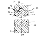
The grooved V-arrangement clamping surface 41 of cutting tip 32 lower surfaces 34 is at the second contact site 66 and ridge V-arrangement clamping surface 64 clamping contacts of 31 times receiving slot rooved faces 56 of blade support, as shown in Figure 8, the surface element 44,45 of the grooved V-arrangement clamping surface 41 of cutting tip 32 lower surfaces 34 respectively with surface element 69,70 adjacency of the ridge V-arrangement clamping surface 64 of 31 times receiving slot rooved faces 56 of blade support, and surface element 44,45 and 69,70 is shared common blunt locking angles 2.Normally 120 °-150 ° of the scopes of locking angle 2.
The ridge V-arrangement clamping surface 40 of cutting tip 32 lower surfaces 34 is at the first contact site 65 and grooved V-arrangement clamping surface 63 clamping contacts of 31 times receiving slot rooved faces 56 of blade support, as shown in figure 10, the surface element 42,43 of the ridge V-arrangement clamping surface 40 of cutting tip 32 lower surfaces 34 respectively with surface element 67,68 adjacency of the grooved V-arrangement clamping surface 63 of 31 times receiving slot rooved faces 56 of blade support, and surface element 42,43 and 67,68 is shared common locking angle 1, and wherein locking angle 1 is less than locking angle 2.Normally 60 °-120 ° of the scopes of locking angle 1.
Compared with between V-arrangement clamping surface element 42,43 and 67,68 at the clamping contact of the first contact site 65 of 31 times receiving slot rooved faces 56 of blade support, appear at the larger distance of principal plane P1 of cutting tip 32 between the V-arrangement clamping surface element 44,45 and 69,70 at the clamping contact of the second contact site 66 of 31 times receiving slot rooved faces 56 of blade support.
As shown in Figure 9, along the longitudinal direction of 31 times receiving slot rooved faces 56 of blade support, between the front step 72 of the backward step 71 of the first contact site 65 and the second contact site 66, between cutting tip 32 and blade support 31, do not produce clamping contact.
Grooved V-arrangement clamping surface 76 clamping contacts of receiving slot rooved face 55 on the ridge V-arrangement clamping surface 46 of cutting tip 32 upper surfaces 33 and the blade support 31, as shown in Figure 9, the surface element 47,48 of the ridge V-arrangement clamping surface 46 of cutting tip 32 upper surfaces 33 respectively with blade support 31 on surface element 77,78 adjacency of grooved V-arrangement clamping surface 76 of receiving slot rooved face 55, surface element 47,48 and 77,78 is shared common locking angle 3, and wherein locking angle 3 is less than locking angle 2.Normally 60 °-120 ° of the scopes of locking angle 3.
The second embodiment of cutting element 130 such as Figure 11 and shown in Figure 12 comprise cutting tip 132 and blade support 131.
Such as Figure 13 and shown in Figure 14, cutting tip 132 comprises upper surface and lower surface 132,134 and all sides 135 of extending between upper surface and lower surface 133,134.All sides 135 comprise front end face and rear end face 136,137, longitudinal axis A 1 ' pass through between front end face and rear end face 136,137.Upper clamping part and lower clamping part 138,139 are respectively formed on upper surface and the lower surface 133,134.
Lower clamping part 139 is comprised of two grooved V-arrangement clamping surfaces 140,141.The first grooved V-arrangement clamping surface 140, as shown in Figure 18, have two surface elements 142,143 that form outside lip angle α 1, and the second grooved V-arrangement clamping surface 141, as shown in figure 16, have two surface elements 144,145 that form blunt outside lip angle α 2, wherein locking angle 1 is less than locking angle 2.The grooved guide surface 184 adjacent with front end face 136 is not the feature of the lower clamping part 139 of cutting tip 132, and the device with lower clamping part 162 clamping contacts of blade support 131 is not provided.
Also according to the second embodiment, cutting tip 132 can be symmetrical about principal plane P 1 ' mirror image, and about perpendicular to longitudinal axis A 1 ' and through the inferior axis A2 ' Rotational Symmetry of all sides 135, described principal plane P1 ' process upper surface and lower surface 133,134 and longitudinal axis A 1 '.Upper peripheral edge and lower periphery 149,150 are formed on upper surface and lower surface 133,134 and the intersection of all sides 135, form cutting edge 151 in upper peripheral edge and lower periphery 149, each a part of 150.
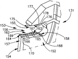
As shown in figure 15, the blade support 131 of the second embodiment comprises bracket head 152, the blade that described bracket head 152 has towards outward opening to the front end 154 of blade support 131 receives slot 153, upper receiving slot rooved face and lower receiving slot rooved face 155,156 share front end 157 from lower receiving slot rooved face 156 to the rear end 158 common longitudinal direction.
Lower clamping part 162 is formed on respectively first and second contact sites 165,166 places adjacent with the rear end 158 of lower receiving slot rooved face 156 and front end 157.The first and second contact sites 165,166 each formed by two ridge V-arrangement clamping surfaces 163,164.The first V-arrangement clamping surface 163 as shown in figure 18, has two surface elements 167,168 of locking angle 1 in forming, the second V-arrangement clamping surface 164, as shown in figure 16, have two surface elements 169,170 that form blunt interior locking angle 2, wherein locking angle 1 is less than locking angle 2.
The upper clamping part 175 that forms on the upper receiving slot rooved face 155 is comprised of single ridge V-arrangement clamping surface 176, as shown in figure 17, has two surface elements 177,178 of locking angle 3 in forming, and wherein locking angle 3 equals locking angle 1.
Along with cutting tip 132 is firmly fixed in the blade support 131, clamping contact appears between cutting tip 132 and blade support 131, and as described below.
The second grooved V-arrangement clamping surface 141 of cutting tip 132 lower surfaces 134 is at the second contact site 66 and the second ridge V-arrangement clamping surface 164 clamping contacts of 131 times receiving slot rooved faces 156 of blade support, as shown in figure 16, the surface element 144,145 of the second grooved V-arrangement clamping surface 141 of cutting tip 132 lower surfaces 134 respectively with surface element 169,170 adjacency of the second ridge V-arrangement clamping surface 164 of 131 times receiving slot rooved faces 156 of blade support, and surface element 144,145 and 169,170 is shared common blunt locking angles 2.
The first grooved V-arrangement clamping surface 40 of cutting tip 132 lower surfaces 134 is at the first contact site 165 and the first ridge V-arrangement clamping surface 163 clamping contacts of 131 times receiving slot rooved faces 156 of blade support, as shown in figure 18, the surface element 142 of the first grooved V-arrangement clamping surface 140 of cutting tip 132 lower surfaces 134,143 respectively with the surface element 167 of the first ridge V-arrangement clamping surface 163 of 131 times receiving slot rooved faces 156 of blade support, 168 adjacency, and surface element 142,143 and 167,168 share common locking angle 1, and wherein locking angle 1 is less than locking angle 2.
Compared with between V-arrangement clamping surface element 142,143 and 167,168 at the clamping contact of the first contact site 165 of 131 times receiving slot rooved faces 156 of blade support, appear at the larger distance of principal plane P1 ' of cutting tip 132 between the V-arrangement clamping surface element 144,145 and 169,170 at the clamping contact of the second contact site 166 of 131 times receiving slot rooved faces 156 of blade support.
As shown in figure 17, between first and second contact site 165,166, between cutting tip 132 and blade support 131, there is not clamping contact along the longitudinal direction of 131 times receiving slot rooved faces 156 of blade support.
Ridge V-arrangement clamping surface 176 clamping contacts of receiving slot rooved face 155 on the grooved V-arrangement clamping surface 146 of cutting tip 132 upper surfaces 133 and the blade support 131, as shown in figure 17, the surface element 147,148 of the grooved V-arrangement clamping surface 146 of cutting tip 132 upper surfaces 133 respectively with blade support 131 on surface element 177,178 adjacency of ridge V-arrangement clamping surface 176 of receiving slot rooved face 155, surface element 147,148 and 177,178 is shared common locking angle 3, and wherein locking angle 3 is less than locking angle 2.
The 3rd embodiment of cutting element 230 such as Figure 19 and shown in Figure 20 comprise cutting tip 232 and blade support 231.
Such as Figure 21 and shown in Figure 22, cutting tip 232 comprises upper surface and lower surface 233,234 and all sides 235 of extending between upper surface and lower surface 233,234.All sides 235 comprise front end face and rear end face 236,237, longitudinal axis A 1 and " pass through between front end face and rear end face 236,237.Upper clamping part and lower clamping part 238,239 are respectively formed on upper surface and the lower surface 233,234.
Lower clamping part 239 is comprised of two grooved V-arrangement clamping surfaces 240,241.The first grooved V-arrangement clamping surface 240 as shown in Figure 26, has two surface elements 242,243 that form outside lip angle α 1, the second grooved V-arrangement clamping surface 241, as shown in figure 24, have two surface elements 244,245 that form outside lip angle α 2, wherein locking angle 1 is less than locking angle 2.
The upper clamping part 238 that forms on the upper surface 233 is comprised of single grooved V-arrangement clamping surface 246, as shown in figure 25, has two surface elements 247,248 that form outside lip angle α 3, and wherein locking angle 3 is less than locking angle 2.
Also according to the 3rd embodiment, cutting tip 232 can be about principal plane P1 " mirror image is symmetrical, described principal plane P1 " through upper surface and lower surface 233,234 and longitudinal axis A 1 ".Upper peripheral edge and lower periphery 249,250 be formed on upper surface and lower surface 233,234 respectively with the intersection of all sides 235, form cutting edge 251 along the part of upper peripheral edge 249.
As shown in figure 23, the blade support 231 of the 3rd embodiment comprises bracket head 252, the blade that described bracket head 252 has towards outward opening to the front end 254 of blade support 231 receives slot 253, upper receiving slot rooved face and lower receiving slot rooved face 255,256 share front end 257 from lower receiving slot rooved face 256 to the rear end 258 common longitudinal direction.
The lower clamping part 262 that is formed on the lower receiving slot rooved face 256 is comprised of two ridge V-arrangement clamping surfaces 263,264, and described two ridge V-arrangement clamping surfaces 263,264 are positioned at the contact site 265,266 that separates along the longitudinal direction of lower receiving slot rooved face 256.The first contact site 265 is positioned at adjacent with rear end 258, two surface elements 267,268 of the first ridge V-arrangement clamping surface 263 form interior locking angle 1 as shown in figure 26, and that the second contact site 266 is positioned at is adjacent with front end 257, two surface elements 269,270 of the second ridge V-arrangement clamping surface 264 form blunt interior locking angle 2 as shown in figure 24, and wherein locking angle 1 is less than locking angle 2.
The upper clamping part 275 that forms on the upper receiving slot rooved face 255 is comprised of single ridge V-arrangement clamping surface 276, has two surface elements 277,278 of locking angle 3 in forming as shown in figure 25, and wherein locking angle 3 is less than locking angle 2.
Along with cutting tip 232 is firmly fixed in the blade support 231, clamping contact appears between cutting tip 232 and blade support 231, and as described below.
The second grooved V-arrangement clamping surface 241 of cutting tip 232 lower surfaces 234 is at the second contact site 266 and the second ridge V-arrangement clamping surface 264 clamping contacts of 231 times receiving slot rooved faces 256 of blade support, as shown in figure 24, the surface element 244,245 of the second grooved V-arrangement clamping surface 241 of cutting tip 232 lower surfaces 234 respectively with surface element 269,270 adjacency of the second ridge V-arrangement clamping surface 264 of 231 times receiving slot rooved faces 256 of blade support, and surface element 244,245 and 269,270 is shared common blunt locking angles 2.
The first grooved V-arrangement clamping surface 240 of cutting tip 232 lower surfaces 234 is at the first contact site 265 and the first ridge V-arrangement clamping surface 263 clamping contacts of 231 times receiving slot rooved faces 256 of blade support, as shown in figure 26, the surface element 242 of the first grooved V-arrangement clamping surface 240 of cutting tip 232 lower surfaces 234,243 respectively with the surface element 267 of the first ridge V-arrangement clamping surface 263 of 231 times receiving slot rooved faces 256 of blade support, 268 adjacency, and surface element 242,243 and 267,268 share common locking angle 1, and wherein locking angle 1 is less than locking angle 2.
Ridge V-arrangement clamping surface 276 clamping contacts of receiving slot rooved face 255 on the grooved V-arrangement clamping surface 246 of cutting tip 232 upper surfaces 233 and the blade support 231, as shown in figure 25, the surface element 247,248 of the grooved V-arrangement clamping surface 246 of cutting tip 232 upper surfaces 233 respectively with blade support 231 on surface element 277,278 adjacency of ridge V-arrangement clamping surface 276 of receiving slot rooved face 255, surface element 247,248 and 277,278 is shared common locking angle 3, and wherein locking angle 3 is less than locking angle 2.
According to some embodiment, be formed on V-arrangement clamping surface 40,140,240; 41,141,241; 46,146,246 surface element 42,43,142,143,242,243; 44,45,144,145,244,245; 47,48,147,148,247, the value of three locking angles 1, α 2 and α 3 between 248 is higher or lower than blade support 31, about 1 ° of the coupling angle of wedge on 131,231 is so that cutting tip 32 after the control assembling, 132,232 with blade support 31,131, between 231 the position in resulting clamping contact zone, thereby reduce in the operation risk that stress is too concentrated, it is common in about 1 ° of error that the expression of used " the common angle of wedge " means the angle of wedge.
Although understand specifically to a certain extent the present invention, should understand in the situation that does not deviate from claimed the spirit or scope of the present invention and can do various substitutions and modifications.
Claims (20)
1. a cutting element (30,130,230), comprise: form the have bracket head blade support (31 of (52,152,252) by the first material, 131,231), and the cutting tip (32 of being made by the second harder material, 132,232), wherein, described cutting tip (32,132,232) can be removably mounted in described blade support (31,131,231) in;
Described cutting tip (32,132,232) comprising:
Upper surface and lower surface (33,133,233; 34,134,234);
At described upper surface and lower surface (33,133,233; All sides (35,135,235) of extending 34,134,234), described all sides (35,135,235) comprise front end face and rear end face (36,136,236; 37,137,237), (A1, A1 ' A1 ") are at described front end face and rear end face (36,136,236 for longitudinal axis; 37,137,237) pass through between;
At described upper surface and lower surface (33,133,233; 34,134,234) periphery (49,149,249 that forms with intersection, described all sides (35,135,235); 50,150,250), wherein, at least a portion of at least one in the described periphery (49,149,249) comprises cutting edge (51,151,251),
Described bracket head (52,152,252) comprising:
Front end (54 towards outward opening to described blade support (31,131,231), 154,254) blade receives slot (53,153,253), wherein, described blade receives slot (53,153,253) and comprises upper receiving slot rooved face and the lower receiving slot rooved face (55 of sharing common longitudinal direction, 155,255; 56,156,256), wherein, described lower receiving slot rooved face (56,156,256) comprise first contact site (65,165,265) adjacent with its rear end (58,158,258) and with its front end (57,157,257) the second adjacent contact site (66,166,266)
Wherein:
Two of described cutting tip (32,132,232) lower surface (34,134,234) V-arrangement clamping surfaces (40,140,240 roughly of first in the V-arrangement clamping surface roughly; 63,163,263) with described lower receiving slot rooved face (56,156,256) clamping contact between is only at described the first contact site (65,165,265) occur, and described cutting tip (32,132,232) lower surface (34,134,234) two V-arrangement clamping surfaces (41,141,241 roughly of second in the V-arrangement clamping surface roughly; 64,164,264) with described lower receiving slot rooved face (56,156,256) between clamping contact only occur at described the second contact site (66,166,266),
And wherein, the described second V-arrangement clamping surface (41,141,241 roughly; 64,164,264) surface element (44,45,144,145,244,245; 69,70,169,170,269,270) form blunt locking angle 2, and the described first V-arrangement clamping surface (40,140,240 roughly; 63,163,263) surface element (42,43,142,143,242,243; 67,68,167,168,267,268) formation is less than the locking angle 1 of described locking angle 2.
2. cutting element as claimed in claim 1 (30,130,230), it is characterized in that described cutting tip (32,132,232) the single roughly V-arrangement clamping surface (46 of upper surface (33,133,233), 146,246) has the surface element (47,48 that forms locking angle 3,147,148,247,248), and with described upper receiving slot rooved face (55,155,255) single roughly V-arrangement clamping surface (76,176, the 276) clamping contact on, this single roughly V-arrangement clamping surface (76,176,276) has the surface element (77 that also forms locking angle 3,78,177,178,277,278).
3. cutting element as claimed in claim 2 (30,130,230) is characterized in that, by the described roughly V-arrangement clamping surface (46,146,246 of described cutting tip (32,132,232) upper surface (33,133,233); The surface element (47,48,147,148,247,248 of surface element 76,176,276) and described upper receiving slot rooved face (55,155,255); 77,78,177,178,277,278) the described locking angle 3 that forms is less than by the described second V-arrangement clamping surface (41,141,241 roughly; 64,164,264) surface element (44,45,144,145,244,245; 69,70,169,170,269,270) the described locking angle 2 that forms.
4. cutting element as claimed in claim 2 (30,130,230) is characterized in that, by the described roughly V-arrangement clamping surface (46,146,246 of described cutting tip (32,132,232) upper surface (33,133,233); The surface element (47,48,147,148,247,248 of surface element 76,176,276) and described upper receiving slot rooved face (55,155,255); 77,78,177,178,277,278) the described locking angle 3 that forms equals by the described first V-arrangement clamping surface (40,140,240 roughly; 63,163,263) surface element (42,43,142,143,242,243; 67,68,167,168,267,268) the described locking angle 1 that forms.
5. cutting element as claimed in claim 1 (30,130,230) is characterized in that, described cutting tip (32,132,232) is about passing through described upper surface and lower surface (33,133,233; 34,134,234) and described longitudinal axis ((P1, P1 ', P1 ") mirror image is symmetrical for the principal plane of A1, A1 ', A1 ").
6. cutting element as claimed in claim 5 (30,130) is characterized in that, with the described first V-arrangement clamping surface (40,140 roughly; 63,163) surface element (42,43,142,143; 67,68,167,168) clamping contact between is compared, the described second V-arrangement clamping surface (41,141 roughly; 64,164) surface element (44,45,144,145; 69,70,169,170) clamping contact between appears at the distance farther with the principal plane (P1, P1 ') of described cutting tip (32,132).
7. cutting element as claimed in claim 1 (30) is characterized in that, described cutting tip (32) lower surface (34) described two roughly V-arrangement clamping surface (40,41) have different longitudinal lengths.
8. a blade support (31,231) comprising:
Bracket head (52,252), it has towards outward opening to described blade support (31, the blade of front end 231) (54,254) receives slot (53,253), wherein, described blade receives slot (53,253) and comprises upper receiving slot rooved face and the lower receiving slot rooved face (55,255 of sharing common longitudinal direction; 56,256); And
Respectively receiving slot rooved face and lower receiving slot rooved face (55,255 on described; 56,256) upper upper clamping part and the lower clamping part (75,275 that forms; 62,262), wherein, described lower clamping part (62,262) has the contact site (65,265 that is positioned at along described lower receiving slot rooved face (56,256) separation; 66,266) two V-arrangement clamping surfaces (63,263 roughly; 64,264);
Wherein:
The first contact site (65,265) be positioned at and described lower receiving slot rooved face (56,256) rear end (58,258) adjacent, and the second contact site (66,266) is positioned at the front end (57 with described lower receiving slot rooved face (56,256), 257) adjacent, wherein, the roughly V-arrangement clamping surface (64 of locating at described the second contact site (66,266), 264) surface element (69,70,269,270) form blunt locking angle 2, and at described the first contact site (65, the surface element (67,68 of the roughly V-arrangement clamping surface (63,263) of 265) locating, 267,268) formation is less than the locking angle 1 of described locking angle 2.
9. blade support as claimed in claim 8 (31,231), wherein, surface element (67 by the roughly V-arrangement clamping surface (63,263) of locating at described the first contact site (65,265), 68,267,268) the described locking angle 1 that forms is acute angle.
10. blade support (31 as claimed in claim 8,231), wherein, described upper clamping part (75,275) has single roughly V-arrangement clamping surface (76,276), described single roughly V-arrangement clamping surface (76,276) has the surface element (77,78 that forms locking angle 3,277,278).
11. blade support as claimed in claim 10 (31,231), wherein, surface element (77 by the roughly V-arrangement clamping surface (76,276) on the described upper clamping part (75,275), 78,277,278) the described locking angle 3 that forms is less than at described lower receiving slot rooved face (56,256) the second contact site (66,266) locate by the surface element (69,70 of V-arrangement clamping surface (64,264) roughly, 269,270) the described locking angle 2 that forms.
12. blade support as claimed in claim 10 (31,231), wherein, surface element (77 by the roughly V-arrangement clamping surface (76,276) on the described upper clamping part (75,275), 78,277,278) the described locking angle 3 that forms equals at described lower receiving slot rooved face (56,256) the first contact site (65,265) locate by the surface element (67,68 of V-arrangement clamping surface (63,263) roughly, 267,268) the described locking angle 1 that forms.
13. a cutting tip (32) comprising:
Upper surface and lower surface (33; 34);
At described upper surface and lower surface (33; All sides (35) of extending 34), described all sides (35) comprise front end face and rear end face (36; 37), longitudinal axis (A1) is at described front end face and rear end face (36; 37) pass through between;
At described upper surface and lower surface (33; 34) periphery (49 that forms with the intersection of described all sides (35); 50), wherein, at least a portion of at least one in the described periphery (49) comprises cutting edge (51); And
Be respectively formed at described upper surface and lower surface (33; 34) the upper clamping part on and lower clamping part (38; 39);
Wherein:
When observing in section, at least one (39) in described upper clamping part and the lower clamping part have more than a V-arrangement clamping surface (40 roughly; 41);
Described more than a V-arrangement clamping surface (40 roughly; 41) surface element (42,43; 44,45) form different locking angle 1 and locking angle 2; And
Described more than a V-arrangement clamping surface (40 roughly; 41) have different longitudinal lengths,
And wherein, described cutting tip (32) is symmetrical about secondary flat (P2) mirror image perpendicular to described longitudinal axis (A1).
14. cutting tip as claimed in claim 13 (32), wherein, described more than one roughly (41) in the V-arrangement clamping surface extend to described rear end face (37) fully from described front end face (36).
15. cutting tip as claimed in claim 14 (32), wherein, the described roughly V-arrangement clamping surface (41) that extends to described rear end face (37) from described front end face (36) fully is grooved V-arrangement clamping surface.
16. cutting tip as claimed in claim 14 (32), wherein, the described roughly V-arrangement clamping surface (41) that extends to described rear end face (37) from described front end face (36) fully has the surface element (44,45) that forms blunt locking angle 2.
17. cutting tip as claimed in claim 13 (32), wherein, described more than one roughly at least one (40) in the V-arrangement clamping surface have the surface element (42,43) that forms sharp locking angle 1.
18. cutting tip as claimed in claim 13 (32), it is symmetrical about principal plane (P1) mirror image by described upper surface and lower surface (33,34) and described longitudinal axis (A1).
19. cutting tip as claimed in claim 13 (32), wherein, two parts of at least one in the described periphery (49) comprise cutting edge (51).
20. cutting tip as claimed in claim 16 (32), wherein, when in section, observing, one (38) in described upper clamping part and the lower clamping part have single roughly V-arrangement clamping surface (46), described single roughly V-arrangement clamping surface (46) has the surface element (47,48) that forms less than the locking angle 3 of locking angle 2.
Applications Claiming Priority (3)
| Application Number | Priority Date | Filing Date | Title |
|---|---|---|---|
| IL191520A IL191520A (en) | 2008-05-18 | 2008-05-18 | Cutting tool and cutting insert therefor |
| IL191520 | 2008-05-18 | ||
| PCT/IL2009/000393 WO2009141815A1 (en) | 2008-05-18 | 2009-04-07 | Cutting tool and cutting insert therefor |
Publications (2)
| Publication Number | Publication Date |
|---|---|
| CN102089105A CN102089105A (en) | 2011-06-08 |
| CN102089105B true CN102089105B (en) | 2013-03-13 |
Family
ID=40871385
Family Applications (1)
| Application Number | Title | Priority Date | Filing Date |
|---|---|---|---|
| CN2009801179478A Active CN102089105B (en) | 2008-05-18 | 2009-04-07 | Cutting tool and cutting insert therefor |
Country Status (15)
| Country | Link |
|---|---|
| US (1) | US8104999B2 (en) |
| EP (1) | EP2293896B1 (en) |
| JP (2) | JP5575753B2 (en) |
| KR (1) | KR101606220B1 (en) |
| CN (1) | CN102089105B (en) |
| AT (1) | ATE543598T1 (en) |
| BR (1) | BRPI0912628B1 (en) |
| CA (1) | CA2719311C (en) |
| ES (1) | ES2381004T3 (en) |
| IL (1) | IL191520A (en) |
| PL (1) | PL2293896T3 (en) |
| PT (1) | PT2293896E (en) |
| RU (1) | RU2477671C2 (en) |
| TW (1) | TWI400135B (en) |
| WO (1) | WO2009141815A1 (en) |
Families Citing this family (42)
| Publication number | Priority date | Publication date | Assignee | Title |
|---|---|---|---|---|
| CN102686343B (en) * | 2009-12-14 | 2015-02-18 | 京瓷株式会社 | Cutting tool holder, cutting tool, and cut workpiece manufacturing method using aforementioned cutting tool |
| KR101075292B1 (en) * | 2010-01-14 | 2011-10-20 | 대구텍 유한회사 | Cutting tool |
| IL205091A (en) * | 2010-04-14 | 2014-01-30 | Iscar Ltd | Cutting tool and cutting insert therefor |
| AT509926B1 (en) * | 2010-06-09 | 2012-12-15 | Boehlerit Gmbh & Co Kg | CUTTING PLATE AND SAW BLADE WITH A VARIETY OF SUCH CUTTING PLATES |
| WO2012017018A1 (en) * | 2010-08-04 | 2012-02-09 | Ceramtec Gmbh | Schneidwerkzeug zum einstechen und stechdrehen |
| US9517509B2 (en) | 2010-12-25 | 2016-12-13 | Kyocera Corporation | Cutting tool and method of manufacturing machined product using the same |
| US8388268B2 (en) | 2011-03-07 | 2013-03-05 | Kennametal Inc. | Cutting assembly |
| JP2014147977A (en) * | 2011-05-23 | 2014-08-21 | Tungaloy Corp | Cutting insert, and cutting tool using cutting insert |
| DE202011101852U1 (en) | 2011-06-14 | 2012-09-19 | Hartmetall-Werkzeugfabrik Paul Horn Gmbh | cutter |
| US8827598B2 (en) | 2011-11-22 | 2014-09-09 | Kennametal Inc. | Cutting assembly with enhanced coolant delivery |
| EP2614908B1 (en) * | 2012-01-13 | 2016-07-27 | Seco Tools Ab | Parting and grooving tool with clamping arrangements |
| DE102012004804C5 (en) * | 2012-03-09 | 2019-03-14 | Kennametal Inc. | Puncture cutting plate and lancing cutting tool |
| CN102601403B (en) * | 2012-03-21 | 2014-07-09 | 株洲钻石切削刀具股份有限公司 | Tool holder for grooving cutting blade |
| WO2014021250A1 (en) * | 2012-07-31 | 2014-02-06 | 京セラ株式会社 | Cutting insert, cutting tool, and method for producing cut workpiece |
| DE102012017424B4 (en) | 2012-09-04 | 2018-07-19 | Kennametal Inc. | Device for lancing cutting tool, lancing cutting plate and lancing cutting tool |
| CN103769506B (en) * | 2012-10-18 | 2016-01-27 | 温芫鋐 | The fusing rifle of tool heat abstractor |
| DE102012111240A1 (en) * | 2012-11-21 | 2014-05-22 | Hartmetall-Werkzeugfabrik Paul Horn Gmbh | Machining tool |
| DE102012111576B4 (en) | 2012-11-29 | 2022-05-25 | Kennametal Inc. | Cutting insert with coolant channel and cutting tool with a tool holder and such a cutting insert |
| US8926233B2 (en) | 2013-01-16 | 2015-01-06 | Kennametal Inc. | Toolholder and cutting insert therefor |
| SE1350795A1 (en) * | 2013-06-28 | 2014-12-29 | Sandvik Intellectual Property | Tools for chip separating machining as well as cutting blade and interchangeable cutter for this. |
| KR101531975B1 (en) * | 2013-08-07 | 2015-06-26 | 한국야금 주식회사 | Assembly of insert and tool holder |
| US20150183029A1 (en) * | 2013-12-30 | 2015-07-02 | Iscar, Ltd. | Multi-Insert Tool Clamp, Tool Holder Assembly And Cutting Tool |
| US9579727B2 (en) | 2014-05-28 | 2017-02-28 | Kennametal Inc. | Cutting assembly with cutting insert having enhanced coolant delivery |
| DE102014116915A1 (en) * | 2014-11-19 | 2016-05-19 | Kennametal Inc. | Tool holder for a cutting insert |
| KR102252055B1 (en) * | 2014-12-05 | 2021-05-17 | 대구텍 유한책임회사 | Rotary cutting tool and cutting insert thereof |
| US10160040B2 (en) * | 2015-11-18 | 2018-12-25 | Iscar, Ltd. | Cutting tool and triangular-shaped indexable cutting insert therefor |
| US9999927B2 (en) * | 2015-11-30 | 2018-06-19 | Iscar, Ltd. | Parting-off tool assembly with single-cutting-edged solid cutting insert and rigid-insert-seat tool |
| US10406605B2 (en) * | 2016-09-13 | 2019-09-10 | Iscar, Ltd. | Cutting tool having an indexable cutting insert retained by a moment force about a pivot axis |
| USD880547S1 (en) | 2017-11-30 | 2020-04-07 | Illinois Tool Works Inc. | Cutting insert |
| USD912708S1 (en) | 2017-11-30 | 2021-03-09 | Illinois Tool Works Inc. | Cutting insert |
| JP7177908B2 (en) * | 2019-02-26 | 2022-11-24 | 京セラ株式会社 | Manufacturing method of cutting insert, cutting tool and cutting work |
| CN113518679B (en) * | 2019-03-13 | 2023-12-22 | 京瓷株式会社 | Cutting insert, cutting tool, and method for manufacturing cut product |
| WO2020189336A1 (en) * | 2019-03-15 | 2020-09-24 | 京セラ株式会社 | Cutting insert, cutting tool, and method for manufacturing cut workpiece |
| CN112605411B (en) * | 2020-12-03 | 2021-12-10 | 株洲华锐精密工具股份有限公司 | Grooving tool |
| WO2023277182A1 (en) * | 2021-07-01 | 2023-01-05 | 京セラ株式会社 | Cutting insert, cutting tool, and method for manufacturing machined product |
| JPWO2023277181A1 (en) * | 2021-07-01 | 2023-01-05 | ||
| US11806793B2 (en) | 2021-11-03 | 2023-11-07 | Iscar, Ltd. | Cutting insert having laterally spaced apart, longitudinally extending wedge abutment surfaces, tool holder and cutting tool |
| CN114406304A (en) * | 2022-01-18 | 2022-04-29 | 厦门金鹭特种合金有限公司 | Cutting tool for grooving, turning and profiling |
| US11766724B1 (en) | 2022-03-16 | 2023-09-26 | Iscar, Ltd. | Cutting tool and tool holder having separate rear abutment and wedged rear stopper surfaces |
| US20230294176A1 (en) * | 2022-03-16 | 2023-09-21 | Iscar, Ltd. | Cutting insert having grooved top and bottom abutment surfaces with inner and outer pairs of wedge angles, and cutting tool |
| US20230356311A1 (en) * | 2022-05-03 | 2023-11-09 | Iscar, Ltd. | Rotationally asymmetric double-ended grooving cutting insert, insert holder and cutting tool |
| US11904393B1 (en) * | 2022-08-18 | 2024-02-20 | Iscar, Ltd. | External grooving insert holder having upper and lower jaws connected by angled hinge portion with cooling channel extending through hinge portion, and cutting tool |
Family Cites Families (13)
| Publication number | Priority date | Publication date | Assignee | Title |
|---|---|---|---|---|
| SU1373478A2 (en) * | 1985-12-24 | 1988-02-15 | Предприятие П/Я Р-6564 | Cutting insert |
| SE452713B (en) | 1986-04-07 | 1987-12-14 | Sandvik Ab | CUTTING TOOLS AND SHOULD BE USED IN THESE TOOLS |
| RU2026772C1 (en) * | 1992-01-21 | 1995-01-20 | Алентьев Константин Иванович | Severing blade with mechanically fastened cutting member |
| JPH0871812A (en) * | 1994-09-12 | 1996-03-19 | Mitsubishi Materials Corp | Grooving tool and throw away tip |
| SE509339C2 (en) * | 1994-12-08 | 1999-01-11 | Seco Tools Ab | Tools and cutters for chip separating machining |
| IL111976A (en) * | 1994-12-14 | 1997-11-20 | Iscar Ltd | Parting or grooving insert |
| SE511934C2 (en) * | 1997-09-24 | 1999-12-20 | Sandvik Ab | Chip separating tool |
| DE19807498A1 (en) * | 1998-02-21 | 1999-09-02 | Horn P Hartmetall Werkzeugfab | Holder for cutting tool inserts |
| RU2197359C2 (en) * | 2000-06-09 | 2003-01-27 | Открытое акционерное общество "Завод им. А.М.Тарасова" | Cutter with mechanically fastened cutting tip |
| JP2004223652A (en) * | 2003-01-23 | 2004-08-12 | Kyocera Corp | Throw away type cutting tool |
| JP4407503B2 (en) * | 2004-12-16 | 2010-02-03 | 三菱マテリアル株式会社 | Cutting insert clamping mechanism |
| DE102005019945B4 (en) * | 2005-04-29 | 2008-07-10 | Kemmer Hartmetallwerkzeuge Gmbh | Carrier tool for a cutting insert with two cutting edges and cutting insert with two cutting edges |
| JP4918799B2 (en) * | 2006-03-24 | 2012-04-18 | 三菱マテリアル株式会社 | Cutting insert clamping mechanism and insert detachable cutting tool |
-
2008
- 2008-05-18 IL IL191520A patent/IL191520A/en active IP Right Grant
- 2008-06-04 TW TW097120758A patent/TWI400135B/en not_active IP Right Cessation
-
2009
- 2009-04-01 US US12/416,474 patent/US8104999B2/en active Active
- 2009-04-07 JP JP2011509078A patent/JP5575753B2/en active Active
- 2009-04-07 AT AT09750267T patent/ATE543598T1/en active
- 2009-04-07 ES ES09750267T patent/ES2381004T3/en active Active
- 2009-04-07 WO PCT/IL2009/000393 patent/WO2009141815A1/en active Application Filing
- 2009-04-07 CA CA2719311A patent/CA2719311C/en active Active
- 2009-04-07 RU RU2010151916/02A patent/RU2477671C2/en active
- 2009-04-07 PL PL09750267T patent/PL2293896T3/en unknown
- 2009-04-07 EP EP09750267A patent/EP2293896B1/en active Active
- 2009-04-07 PT PT09750267T patent/PT2293896E/en unknown
- 2009-04-07 BR BRPI0912628-7A patent/BRPI0912628B1/en active IP Right Grant
- 2009-04-07 KR KR1020107025759A patent/KR101606220B1/en active IP Right Grant
- 2009-04-07 CN CN2009801179478A patent/CN102089105B/en active Active
-
2014
- 2014-02-25 JP JP2014034533A patent/JP5706015B2/en active Active
Also Published As
| Publication number | Publication date |
|---|---|
| IL191520A (en) | 2012-04-30 |
| BRPI0912628A2 (en) | 2016-01-26 |
| TW200950906A (en) | 2009-12-16 |
| KR101606220B1 (en) | 2016-03-24 |
| IL191520A0 (en) | 2008-12-29 |
| US8104999B2 (en) | 2012-01-31 |
| RU2477671C2 (en) | 2013-03-20 |
| JP2011520630A (en) | 2011-07-21 |
| EP2293896B1 (en) | 2012-02-01 |
| WO2009141815A1 (en) | 2009-11-26 |
| TWI400135B (en) | 2013-07-01 |
| BRPI0912628B1 (en) | 2020-10-06 |
| CA2719311A1 (en) | 2009-11-26 |
| JP5706015B2 (en) | 2015-04-22 |
| RU2010151916A (en) | 2012-06-27 |
| US20090285645A1 (en) | 2009-11-19 |
| KR20110018312A (en) | 2011-02-23 |
| JP2014097571A (en) | 2014-05-29 |
| EP2293896A1 (en) | 2011-03-16 |
| ATE543598T1 (en) | 2012-02-15 |
| JP5575753B2 (en) | 2014-08-20 |
| PL2293896T3 (en) | 2012-06-29 |
| CN102089105A (en) | 2011-06-08 |
| PT2293896E (en) | 2012-03-22 |
| ES2381004T3 (en) | 2012-05-22 |
| CA2719311C (en) | 2016-01-12 |
Similar Documents
| Publication | Publication Date | Title |
|---|---|---|
| CN102089105B (en) | Cutting tool and cutting insert therefor | |
| CN102378658B (en) | Cutting tool assembly and tool holder therefor | |
| EP2558235B1 (en) | Cutting tool | |
| CN1833801B (en) | A cutting insert and a tool for chip removing machining, as well as an attachment for such tools | |
| US7534075B2 (en) | Knife plate and tool for machining bore surfaces | |
| CN108602130B (en) | Face grooving tool body for metal cutting | |
| CN105081376A (en) | Turning tool holder and cutting tool insert | |
| JP7313147B2 (en) | Swiss-type turning insert with chipformer configuration with rising ridge | |
| CN109843484B (en) | Turning insert | |
| JP5196077B2 (en) | Cutting inserts and cutting edge changeable turning tools | |
| US4087194A (en) | Cutting tool | |
| US6074138A (en) | Cutting-off insert having a thin reinforced wall forming a cutting edge | |
| JP2019018288A (en) | Cutting insert | |
| EP3512656B1 (en) | Cutting tool having an indexable cutting insert | |
| US6231274B1 (en) | End mill | |
| KR102464805B1 (en) | Cutting insert with split cutting edge with leading and trailing part cutting edges | |
| KR20200127161A (en) | Turning tool for metal cutting with coolant channels | |
| CN111448021B (en) | High-speed feed cutting blade for narrow-width cutting operations | |
| US20200189012A1 (en) | Ball nose and mill insert, a ball nose end mill tool body and a ball nose end mill | |
| JP3690676B2 (en) | Cutting tool holder and cutting tool using the same | |
| JP4816041B2 (en) | Insert type drill and insert | |
| CN117157161A (en) | Cutting insert, cutting tool, and method for manufacturing cut product | |
| EP4313454A1 (en) | Cutting insert and cutting tool |
Legal Events
| Date | Code | Title | Description |
|---|---|---|---|
| C06 | Publication | ||
| PB01 | Publication | ||
| C10 | Entry into substantive examination | ||
| SE01 | Entry into force of request for substantive examination | ||
| C14 | Grant of patent or utility model | ||
| GR01 | Patent grant |