CN102076874A - A method for manufacturing a steel component, a weld seam, a welded steel component, and a bearing component - Google Patents
A method for manufacturing a steel component, a weld seam, a welded steel component, and a bearing component Download PDFInfo
- Publication number
- CN102076874A CN102076874A CN200980125484XA CN200980125484A CN102076874A CN 102076874 A CN102076874 A CN 102076874A CN 200980125484X A CN200980125484X A CN 200980125484XA CN 200980125484 A CN200980125484 A CN 200980125484A CN 102076874 A CN102076874 A CN 102076874A
- Authority
- CN
- China
- Prior art keywords
- steel parts
- steel
- parts
- welding
- weld seam
- Prior art date
- Legal status (The legal status is an assumption and is not a legal conclusion. Google has not performed a legal analysis and makes no representation as to the accuracy of the status listed.)
- Pending
Links
- 229910000831 Steel Inorganic materials 0.000 title claims abstract description 222
- 239000010959 steel Substances 0.000 title claims abstract description 222
- 238000000034 method Methods 0.000 title claims abstract description 62
- 238000004519 manufacturing process Methods 0.000 title claims abstract description 6
- 238000003466 welding Methods 0.000 claims abstract description 86
- 238000001816 cooling Methods 0.000 claims abstract description 23
- 229910052799 carbon Inorganic materials 0.000 claims abstract description 19
- OKTJSMMVPCPJKN-UHFFFAOYSA-N Carbon Chemical compound [C] OKTJSMMVPCPJKN-UHFFFAOYSA-N 0.000 claims abstract description 17
- 238000010438 heat treatment Methods 0.000 claims abstract description 7
- 230000000694 effects Effects 0.000 claims abstract description 4
- 235000019362 perlite Nutrition 0.000 claims description 9
- 239000010451 perlite Substances 0.000 claims description 9
- 230000007704 transition Effects 0.000 claims description 9
- 238000000137 annealing Methods 0.000 claims description 7
- 229910000859 α-Fe Inorganic materials 0.000 claims description 7
- 208000034189 Sclerosis Diseases 0.000 claims description 5
- 230000009466 transformation Effects 0.000 abstract description 9
- 238000005304 joining Methods 0.000 abstract 1
- 230000008569 process Effects 0.000 description 15
- 238000005096 rolling process Methods 0.000 description 13
- 208000037656 Respiratory Sounds Diseases 0.000 description 9
- 230000001681 protective effect Effects 0.000 description 5
- 230000008901 benefit Effects 0.000 description 4
- 229910001566 austenite Inorganic materials 0.000 description 3
- 230000015572 biosynthetic process Effects 0.000 description 3
- 238000005516 engineering process Methods 0.000 description 3
- 239000007788 liquid Substances 0.000 description 3
- 238000003754 machining Methods 0.000 description 3
- 229910000734 martensite Inorganic materials 0.000 description 3
- XEEYBQQBJWHFJM-UHFFFAOYSA-N Iron Chemical compound [Fe] XEEYBQQBJWHFJM-UHFFFAOYSA-N 0.000 description 2
- 229910001563 bainite Inorganic materials 0.000 description 2
- 239000000945 filler Substances 0.000 description 2
- 239000000314 lubricant Substances 0.000 description 2
- 239000000463 material Substances 0.000 description 2
- 238000004080 punching Methods 0.000 description 2
- 238000007789 sealing Methods 0.000 description 2
- 229910000975 Carbon steel Inorganic materials 0.000 description 1
- 238000002441 X-ray diffraction Methods 0.000 description 1
- 229910045601 alloy Inorganic materials 0.000 description 1
- 239000000956 alloy Substances 0.000 description 1
- JZQOJFLIJNRDHK-CMDGGOBGSA-N alpha-irone Chemical compound CC1CC=C(C)C(\C=C\C(C)=O)C1(C)C JZQOJFLIJNRDHK-CMDGGOBGSA-N 0.000 description 1
- 230000001195 anabolic effect Effects 0.000 description 1
- 238000005452 bending Methods 0.000 description 1
- 239000010962 carbon steel Substances 0.000 description 1
- 230000008859 change Effects 0.000 description 1
- 239000013078 crystal Substances 0.000 description 1
- 238000010586 diagram Methods 0.000 description 1
- 238000009826 distribution Methods 0.000 description 1
- 238000010891 electric arc Methods 0.000 description 1
- 238000010894 electron beam technology Methods 0.000 description 1
- 239000004744 fabric Substances 0.000 description 1
- 239000000835 fiber Substances 0.000 description 1
- 230000006872 improvement Effects 0.000 description 1
- 230000006698 induction Effects 0.000 description 1
- 238000007689 inspection Methods 0.000 description 1
- 229910052742 iron Inorganic materials 0.000 description 1
- 239000000155 melt Substances 0.000 description 1
- 239000002184 metal Substances 0.000 description 1
- 229910052751 metal Inorganic materials 0.000 description 1
- 150000001247 metal acetylides Chemical class 0.000 description 1
- 238000005057 refrigeration Methods 0.000 description 1
- 238000007669 thermal treatment Methods 0.000 description 1
Images


Classifications
-
- C—CHEMISTRY; METALLURGY
- C21—METALLURGY OF IRON
- C21D—MODIFYING THE PHYSICAL STRUCTURE OF FERROUS METALS; GENERAL DEVICES FOR HEAT TREATMENT OF FERROUS OR NON-FERROUS METALS OR ALLOYS; MAKING METAL MALLEABLE, e.g. BY DECARBURISATION OR TEMPERING
- C21D9/00—Heat treatment, e.g. annealing, hardening, quenching or tempering, adapted for particular articles; Furnaces therefor
- C21D9/50—Heat treatment, e.g. annealing, hardening, quenching or tempering, adapted for particular articles; Furnaces therefor for welded joints
-
- F—MECHANICAL ENGINEERING; LIGHTING; HEATING; WEAPONS; BLASTING
- F16—ENGINEERING ELEMENTS AND UNITS; GENERAL MEASURES FOR PRODUCING AND MAINTAINING EFFECTIVE FUNCTIONING OF MACHINES OR INSTALLATIONS; THERMAL INSULATION IN GENERAL
- F16C—SHAFTS; FLEXIBLE SHAFTS; ELEMENTS OR CRANKSHAFT MECHANISMS; ROTARY BODIES OTHER THAN GEARING ELEMENTS; BEARINGS
- F16C33/00—Parts of bearings; Special methods for making bearings or parts thereof
- F16C33/02—Parts of sliding-contact bearings
- F16C33/04—Brasses; Bushes; Linings
- F16C33/06—Sliding surface mainly made of metal
- F16C33/14—Special methods of manufacture; Running-in
-
- C—CHEMISTRY; METALLURGY
- C21—METALLURGY OF IRON
- C21D—MODIFYING THE PHYSICAL STRUCTURE OF FERROUS METALS; GENERAL DEVICES FOR HEAT TREATMENT OF FERROUS OR NON-FERROUS METALS OR ALLOYS; MAKING METAL MALLEABLE, e.g. BY DECARBURISATION OR TEMPERING
- C21D1/00—General methods or devices for heat treatment, e.g. annealing, hardening, quenching or tempering
- C21D1/18—Hardening; Quenching with or without subsequent tempering
-
- C—CHEMISTRY; METALLURGY
- C21—METALLURGY OF IRON
- C21D—MODIFYING THE PHYSICAL STRUCTURE OF FERROUS METALS; GENERAL DEVICES FOR HEAT TREATMENT OF FERROUS OR NON-FERROUS METALS OR ALLOYS; MAKING METAL MALLEABLE, e.g. BY DECARBURISATION OR TEMPERING
- C21D1/00—General methods or devices for heat treatment, e.g. annealing, hardening, quenching or tempering
- C21D1/26—Methods of annealing
- C21D1/32—Soft annealing, e.g. spheroidising
-
- C—CHEMISTRY; METALLURGY
- C21—METALLURGY OF IRON
- C21D—MODIFYING THE PHYSICAL STRUCTURE OF FERROUS METALS; GENERAL DEVICES FOR HEAT TREATMENT OF FERROUS OR NON-FERROUS METALS OR ALLOYS; MAKING METAL MALLEABLE, e.g. BY DECARBURISATION OR TEMPERING
- C21D9/00—Heat treatment, e.g. annealing, hardening, quenching or tempering, adapted for particular articles; Furnaces therefor
- C21D9/38—Heat treatment, e.g. annealing, hardening, quenching or tempering, adapted for particular articles; Furnaces therefor for roll bodies
-
- F—MECHANICAL ENGINEERING; LIGHTING; HEATING; WEAPONS; BLASTING
- F16—ENGINEERING ELEMENTS AND UNITS; GENERAL MEASURES FOR PRODUCING AND MAINTAINING EFFECTIVE FUNCTIONING OF MACHINES OR INSTALLATIONS; THERMAL INSULATION IN GENERAL
- F16C—SHAFTS; FLEXIBLE SHAFTS; ELEMENTS OR CRANKSHAFT MECHANISMS; ROTARY BODIES OTHER THAN GEARING ELEMENTS; BEARINGS
- F16C33/00—Parts of bearings; Special methods for making bearings or parts thereof
- F16C33/30—Parts of ball or roller bearings
- F16C33/58—Raceways; Race rings
- F16C33/60—Raceways; Race rings divided or split, e.g. comprising two juxtaposed rings
-
- F—MECHANICAL ENGINEERING; LIGHTING; HEATING; WEAPONS; BLASTING
- F16—ENGINEERING ELEMENTS AND UNITS; GENERAL MEASURES FOR PRODUCING AND MAINTAINING EFFECTIVE FUNCTIONING OF MACHINES OR INSTALLATIONS; THERMAL INSULATION IN GENERAL
- F16C—SHAFTS; FLEXIBLE SHAFTS; ELEMENTS OR CRANKSHAFT MECHANISMS; ROTARY BODIES OTHER THAN GEARING ELEMENTS; BEARINGS
- F16C35/00—Rigid support of bearing units; Housings, e.g. caps, covers
- F16C35/04—Rigid support of bearing units; Housings, e.g. caps, covers in the case of ball or roller bearings
- F16C35/06—Mounting or dismounting of ball or roller bearings; Fixing them onto shaft or in housing
-
- C—CHEMISTRY; METALLURGY
- C21—METALLURGY OF IRON
- C21D—MODIFYING THE PHYSICAL STRUCTURE OF FERROUS METALS; GENERAL DEVICES FOR HEAT TREATMENT OF FERROUS OR NON-FERROUS METALS OR ALLOYS; MAKING METAL MALLEABLE, e.g. BY DECARBURISATION OR TEMPERING
- C21D2211/00—Microstructure comprising significant phases
- C21D2211/003—Cementite
-
- C—CHEMISTRY; METALLURGY
- C21—METALLURGY OF IRON
- C21D—MODIFYING THE PHYSICAL STRUCTURE OF FERROUS METALS; GENERAL DEVICES FOR HEAT TREATMENT OF FERROUS OR NON-FERROUS METALS OR ALLOYS; MAKING METAL MALLEABLE, e.g. BY DECARBURISATION OR TEMPERING
- C21D2211/00—Microstructure comprising significant phases
- C21D2211/005—Ferrite
-
- C—CHEMISTRY; METALLURGY
- C21—METALLURGY OF IRON
- C21D—MODIFYING THE PHYSICAL STRUCTURE OF FERROUS METALS; GENERAL DEVICES FOR HEAT TREATMENT OF FERROUS OR NON-FERROUS METALS OR ALLOYS; MAKING METAL MALLEABLE, e.g. BY DECARBURISATION OR TEMPERING
- C21D2211/00—Microstructure comprising significant phases
- C21D2211/009—Pearlite
-
- F—MECHANICAL ENGINEERING; LIGHTING; HEATING; WEAPONS; BLASTING
- F16—ENGINEERING ELEMENTS AND UNITS; GENERAL MEASURES FOR PRODUCING AND MAINTAINING EFFECTIVE FUNCTIONING OF MACHINES OR INSTALLATIONS; THERMAL INSULATION IN GENERAL
- F16C—SHAFTS; FLEXIBLE SHAFTS; ELEMENTS OR CRANKSHAFT MECHANISMS; ROTARY BODIES OTHER THAN GEARING ELEMENTS; BEARINGS
- F16C19/00—Bearings with rolling contact, for exclusively rotary movement
- F16C19/02—Bearings with rolling contact, for exclusively rotary movement with bearing balls essentially of the same size in one or more circular rows
- F16C19/14—Bearings with rolling contact, for exclusively rotary movement with bearing balls essentially of the same size in one or more circular rows for both radial and axial load
- F16C19/18—Bearings with rolling contact, for exclusively rotary movement with bearing balls essentially of the same size in one or more circular rows for both radial and axial load with two or more rows of balls
- F16C19/181—Bearings with rolling contact, for exclusively rotary movement with bearing balls essentially of the same size in one or more circular rows for both radial and axial load with two or more rows of balls with angular contact
- F16C19/183—Bearings with rolling contact, for exclusively rotary movement with bearing balls essentially of the same size in one or more circular rows for both radial and axial load with two or more rows of balls with angular contact with two rows at opposite angles
- F16C19/184—Bearings with rolling contact, for exclusively rotary movement with bearing balls essentially of the same size in one or more circular rows for both radial and axial load with two or more rows of balls with angular contact with two rows at opposite angles in O-arrangement
-
- F—MECHANICAL ENGINEERING; LIGHTING; HEATING; WEAPONS; BLASTING
- F16—ENGINEERING ELEMENTS AND UNITS; GENERAL MEASURES FOR PRODUCING AND MAINTAINING EFFECTIVE FUNCTIONING OF MACHINES OR INSTALLATIONS; THERMAL INSULATION IN GENERAL
- F16C—SHAFTS; FLEXIBLE SHAFTS; ELEMENTS OR CRANKSHAFT MECHANISMS; ROTARY BODIES OTHER THAN GEARING ELEMENTS; BEARINGS
- F16C19/00—Bearings with rolling contact, for exclusively rotary movement
- F16C19/22—Bearings with rolling contact, for exclusively rotary movement with bearing rollers essentially of the same size in one or more circular rows, e.g. needle bearings
- F16C19/34—Bearings with rolling contact, for exclusively rotary movement with bearing rollers essentially of the same size in one or more circular rows, e.g. needle bearings for both radial and axial load
- F16C19/38—Bearings with rolling contact, for exclusively rotary movement with bearing rollers essentially of the same size in one or more circular rows, e.g. needle bearings for both radial and axial load with two or more rows of rollers
-
- F—MECHANICAL ENGINEERING; LIGHTING; HEATING; WEAPONS; BLASTING
- F16—ENGINEERING ELEMENTS AND UNITS; GENERAL MEASURES FOR PRODUCING AND MAINTAINING EFFECTIVE FUNCTIONING OF MACHINES OR INSTALLATIONS; THERMAL INSULATION IN GENERAL
- F16C—SHAFTS; FLEXIBLE SHAFTS; ELEMENTS OR CRANKSHAFT MECHANISMS; ROTARY BODIES OTHER THAN GEARING ELEMENTS; BEARINGS
- F16C2220/00—Shaping
- F16C2220/80—Shaping by separating parts, e.g. by severing, cracking
- F16C2220/84—Shaping by separating parts, e.g. by severing, cracking by perforating; by punching; by stamping-out
-
- F—MECHANICAL ENGINEERING; LIGHTING; HEATING; WEAPONS; BLASTING
- F16—ENGINEERING ELEMENTS AND UNITS; GENERAL MEASURES FOR PRODUCING AND MAINTAINING EFFECTIVE FUNCTIONING OF MACHINES OR INSTALLATIONS; THERMAL INSULATION IN GENERAL
- F16C—SHAFTS; FLEXIBLE SHAFTS; ELEMENTS OR CRANKSHAFT MECHANISMS; ROTARY BODIES OTHER THAN GEARING ELEMENTS; BEARINGS
- F16C2226/00—Joining parts; Fastening; Assembling or mounting parts
- F16C2226/10—Force connections, e.g. clamping
- F16C2226/12—Force connections, e.g. clamping by press-fit, e.g. plug-in
-
- F—MECHANICAL ENGINEERING; LIGHTING; HEATING; WEAPONS; BLASTING
- F16—ENGINEERING ELEMENTS AND UNITS; GENERAL MEASURES FOR PRODUCING AND MAINTAINING EFFECTIVE FUNCTIONING OF MACHINES OR INSTALLATIONS; THERMAL INSULATION IN GENERAL
- F16C—SHAFTS; FLEXIBLE SHAFTS; ELEMENTS OR CRANKSHAFT MECHANISMS; ROTARY BODIES OTHER THAN GEARING ELEMENTS; BEARINGS
- F16C2226/00—Joining parts; Fastening; Assembling or mounting parts
- F16C2226/30—Material joints
- F16C2226/36—Material joints by welding
-
- F—MECHANICAL ENGINEERING; LIGHTING; HEATING; WEAPONS; BLASTING
- F16—ENGINEERING ELEMENTS AND UNITS; GENERAL MEASURES FOR PRODUCING AND MAINTAINING EFFECTIVE FUNCTIONING OF MACHINES OR INSTALLATIONS; THERMAL INSULATION IN GENERAL
- F16C—SHAFTS; FLEXIBLE SHAFTS; ELEMENTS OR CRANKSHAFT MECHANISMS; ROTARY BODIES OTHER THAN GEARING ELEMENTS; BEARINGS
- F16C2226/00—Joining parts; Fastening; Assembling or mounting parts
- F16C2226/50—Positive connections
- F16C2226/60—Positive connections with threaded parts, e.g. bolt and nut connections
-
- F—MECHANICAL ENGINEERING; LIGHTING; HEATING; WEAPONS; BLASTING
- F16—ENGINEERING ELEMENTS AND UNITS; GENERAL MEASURES FOR PRODUCING AND MAINTAINING EFFECTIVE FUNCTIONING OF MACHINES OR INSTALLATIONS; THERMAL INSULATION IN GENERAL
- F16C—SHAFTS; FLEXIBLE SHAFTS; ELEMENTS OR CRANKSHAFT MECHANISMS; ROTARY BODIES OTHER THAN GEARING ELEMENTS; BEARINGS
- F16C23/00—Bearings for exclusively rotary movement adjustable for aligning or positioning
- F16C23/06—Ball or roller bearings
- F16C23/08—Ball or roller bearings self-adjusting
- F16C23/082—Ball or roller bearings self-adjusting by means of at least one substantially spherical surface
- F16C23/086—Ball or roller bearings self-adjusting by means of at least one substantially spherical surface forming a track for rolling elements
-
- F—MECHANICAL ENGINEERING; LIGHTING; HEATING; WEAPONS; BLASTING
- F16—ENGINEERING ELEMENTS AND UNITS; GENERAL MEASURES FOR PRODUCING AND MAINTAINING EFFECTIVE FUNCTIONING OF MACHINES OR INSTALLATIONS; THERMAL INSULATION IN GENERAL
- F16C—SHAFTS; FLEXIBLE SHAFTS; ELEMENTS OR CRANKSHAFT MECHANISMS; ROTARY BODIES OTHER THAN GEARING ELEMENTS; BEARINGS
- F16C2300/00—Application independent of particular apparatuses
- F16C2300/02—General use or purpose, i.e. no use, purpose, special adaptation or modification indicated or a wide variety of uses mentioned
-
- F—MECHANICAL ENGINEERING; LIGHTING; HEATING; WEAPONS; BLASTING
- F16—ENGINEERING ELEMENTS AND UNITS; GENERAL MEASURES FOR PRODUCING AND MAINTAINING EFFECTIVE FUNCTIONING OF MACHINES OR INSTALLATIONS; THERMAL INSULATION IN GENERAL
- F16C—SHAFTS; FLEXIBLE SHAFTS; ELEMENTS OR CRANKSHAFT MECHANISMS; ROTARY BODIES OTHER THAN GEARING ELEMENTS; BEARINGS
- F16C2326/00—Articles relating to transporting
- F16C2326/01—Parts of vehicles in general
- F16C2326/02—Wheel hubs or castors
-
- F—MECHANICAL ENGINEERING; LIGHTING; HEATING; WEAPONS; BLASTING
- F16—ENGINEERING ELEMENTS AND UNITS; GENERAL MEASURES FOR PRODUCING AND MAINTAINING EFFECTIVE FUNCTIONING OF MACHINES OR INSTALLATIONS; THERMAL INSULATION IN GENERAL
- F16C—SHAFTS; FLEXIBLE SHAFTS; ELEMENTS OR CRANKSHAFT MECHANISMS; ROTARY BODIES OTHER THAN GEARING ELEMENTS; BEARINGS
- F16C33/00—Parts of bearings; Special methods for making bearings or parts thereof
- F16C33/30—Parts of ball or roller bearings
- F16C33/46—Cages for rollers or needles
- F16C33/54—Cages for rollers or needles made from wire, strips, or sheet metal
- F16C33/542—Cages for rollers or needles made from wire, strips, or sheet metal made from sheet metal
- F16C33/543—Cages for rollers or needles made from wire, strips, or sheet metal made from sheet metal from a single part
-
- Y—GENERAL TAGGING OF NEW TECHNOLOGICAL DEVELOPMENTS; GENERAL TAGGING OF CROSS-SECTIONAL TECHNOLOGIES SPANNING OVER SEVERAL SECTIONS OF THE IPC; TECHNICAL SUBJECTS COVERED BY FORMER USPC CROSS-REFERENCE ART COLLECTIONS [XRACs] AND DIGESTS
- Y10—TECHNICAL SUBJECTS COVERED BY FORMER USPC
- Y10T—TECHNICAL SUBJECTS COVERED BY FORMER US CLASSIFICATION
- Y10T428/00—Stock material or miscellaneous articles
- Y10T428/12—All metal or with adjacent metals
- Y10T428/12493—Composite; i.e., plural, adjacent, spatially distinct metal components [e.g., layers, joint, etc.]
- Y10T428/12639—Adjacent, identical composition, components
- Y10T428/12646—Group VIII or IB metal-base
- Y10T428/12653—Fe, containing 0.01-1.7% carbon [i.e., steel]
Landscapes
- Engineering & Computer Science (AREA)
- Chemical & Material Sciences (AREA)
- Mechanical Engineering (AREA)
- General Engineering & Computer Science (AREA)
- Crystallography & Structural Chemistry (AREA)
- Thermal Sciences (AREA)
- Physics & Mathematics (AREA)
- Materials Engineering (AREA)
- Metallurgy (AREA)
- Organic Chemistry (AREA)
- Heat Treatment Of Articles (AREA)
- Rolling Contact Bearings (AREA)
- Butt Welding And Welding Of Specific Article (AREA)
- Arc Welding In General (AREA)
- Laser Beam Processing (AREA)
Abstract
The invention concerns a method for manufacturing a steel component (6, 11) comprising a first steel part (7) and a second steel part (8), the first (7) and second (8) steel part having a carbon content up to 1.5 weight percent, The method is comprising: Heating (1), at least partly, the first steel part (7), and at least partly, the second steel part (8), to above the alpha/gamma transformation temperature, and joining (2) the first steel part (7) and the second steel part (8) by welding, the welding taking place at a temperature above the alpha/gamma transformation temperature, and cooling (3) such that hardening effects are avoided. The invention further concerns weld seams (9), welded steel components (6, 11), and bearing components (11, 15, 20, 22, 26, 27, 31).
Description
Technical field
According to first aspect, the present invention relates to be used to make the method for steel parts.
According to second aspect, the present invention relates to first weld seam.
According to the third aspect, the present invention relates to the first welding steel parts.
According to fourth aspect, the present invention relates to second weld seam.
According to the 5th aspect, the present invention relates to the second welding steel parts.
According to the 6th aspect, the present invention relates to the 3rd welding steel parts.
According to the 7th aspect, the present invention relates to make the method for parts of bearings.
According to eight aspect, the present invention relates to comprise the parts of bearings of weld seam.
Background technology
Welding is the effective ways that engage the steel parts.But along with steel carbon-content raises, the problem that occurs in the welding process is more and more.Known and carbon content raise relevant problem for example may be cause in welding process, generation crackle easily during almost directly after welding or at carry load.This is because the fragility plate martensite crystal grain that is formed in melt region and the heat-affected zone in the welding process is very huge.
Summary of the invention
The purpose of this invention is to provide the method that a kind of welding has the steel parts of good strength, good fatigue resistance and supporting capacity, and described method is simple and with low cost.
There are many aspects in the present invention, and wherein the method according to first aspect produces the conclusion that constitutes otherwise basis.
According to first aspect present invention, utilize a kind of method of making the steel parts to realize above-mentioned purpose, described steel parts comprise first steel part and the second steel part, the carbon content of wherein said first and second steel is up to 1.5 weight percents (wt%).According to described method, first steel parts and second steel partly are heated to α/more than the γ transition temperature at least in part.In subsequent step, first steel part and second steel are partly by welded joint, and welding occurs in the above temperature of α/γ transition temperature.In subsequent step, apply cooling to avoid hardening effect.Cause first weld seam like this according to second aspect present invention.
Weld by temperature (austenite condition), and solidify weldment and further cool off in a controlled manner, can control phase transformation at α/more than the γ transition temperature, stoped like this formation hard mutually with fragility mutually.With steel, need the part that is engaged with each other or parts to be heated at least a little more than the temperature of α iron (under the situation of 100Cr6, being ferrite+carbide) to γ iron (austenite) phase transformation, it is about 750 to 850 ℃, to cause carbide to dissolve gradually, and at time and temperature, when all carbide dissolves, grain growth will take place.If under said temperature, weld, make that all material in the welding region is under the austenite condition, then a large amount of carbide or whole in some cases carbide will can not dissolve.The liquid melt region will have into whole carbon of complete melt.If liquid welding metal and contiguous heat affected zone are solidified and cool offs and suitably do not control, then in the liquid melt region the complete melt of whole carbon will to cause taking place the risk of crackle very high.This control is realized by the present invention, feasible known compared to prior art situation, and the risk of weldment generation crackle is less.
Melt region, heat affected zone and residue steel solidify and cool off and need control from welding temperature.In principle, rate of cooling should make and can not undergo phase transition to any sclerosis phase (martensite or bainite).If process of cooling is well controlled, then in melt region (weldment) and heat affected zone, form pearlitic structure wholly or in part, and the remainder of welding assembly is heated to α/more than the γ transition temperature.In embodiment, the little grain boundary carbide with limited grain-size is formed in the melt region (weldment).The quantity of grain boundary carbide depends on total carbon content and rate of cooling.
Final microtexture after welding and the controlled cooling should be a pearlitic structure wholly or in part, and in one embodiment, has a small amount of discrete grain boundary carbide and acceptable grain-size.Perlite, carbide and ferritic development when the total carbon content of available has determined to cool off with controllable rate in the steel.Cause the middle compared to prior art known cases of weldment like this, the risk that crackle takes place is less.
In the microtexture after controlled cooling, soft steel has perlite and adds ferrite, perhaps all is perlite.The soft steel that carbon content is approximately 0.7wt% will form complete perlite microtexture, and if carbon content be lower than about 0.7wt%, then, formation is had ferritic-pearlitic after welding process is carried out controlled cooling.Ferrite quantity reduces and increases along with carbon content.
Carrying out controlled cooling purpose after the welding is: avoid taking place undesirable phase transformation, for example sclerosis; Avoid developing among weldment and the HAZ and internal stress; In welding assembly, form uniform microtexture, the thermal treatment after preparing to be used to weld, for example Spheroidizing Annealing/sclerosis etc.; Make welding postheat treatment parts prepare to be used for machining or other processing, to give these parts " soft processing " shape and size; The configuration parts are hardened to the microstructure properties of requirement.
Controlled cooling relates to numerous factors, for example is used to weld continuous cooling transformation (CCT) curve of steel.For example, in one embodiment, for 1% carbon steel, when cooling off through the perlitic range on the CCT curve, steel from about 670 degree, have formation the complete perlite of a certain amount of grain boundary carbide to perlitic transformation.The shape and size of welding assembly are depended in time-temperature/circulation.Transformation in the controlled process of cooling will be determined at the cross section of parts.This may be different from the naturally cooling in the protective atmosphere, finishes transformation up to whole parts.For example, when too big, the steel core will keep too hot and can not change, and will form excessive grain boundary carbide in the parts cross section.In this case, after the parts surface zone has been changed perlite into, can implement to improve rate of cooling.
For example; in one embodiment, can be in protective atmosphere, in 860 degree enforcement welding, the temperature in the weldment molten bath is higher than 1600 degree (steel of fusing); parts are in the protective atmosphere and cooling, are cooled to 860 degree up to whole parts (perhaps preheating the zone) and welding region.This process may spend some minutes.Since 860 degree, the temperature shown in described parts can be cooled on the CCT curve.Further refrigeration cycle is determined by above-mentioned factor.In one embodiment, described parts are transferred in the stove and accessory and in protective atmosphere and are cooled down in stove and accessory, to form pearlitic structure.
In one embodiment, described method further comprises the soft annealing step.By increasing this step, second weld seam according to fourth aspect present invention is provided, wherein said weld seam will comprise ferrite and carbide.This also helps further processing, for example welds the machining or the distortion of steel parts.Known situation has compared to prior art produced the less weld seam of crackle risk.
In one embodiment, described method further comprises the step of the described steel parts that harden.By this step, can give the required attribute of function that welding steel parts are realized requirement.This for example can be implemented by martensite or bainite by sclerosis.Also can implement surface hardening, such as induction hardening, laser hardening etc.
In one embodiment, can in protective atmosphere, implement heating, welding or cooling.
In one embodiment, utilize the power beam welding process, for example laser welding or electron beam welding fetch and implement welding.
In one embodiment, utilize electric arc welding process to implement described welding.
In one embodiment, utilize to mix welding process for example power beam implement to weld with the anabolic process of arc welding.The example of this process for example is that laser welding adds GMAW (MIG).
In one embodiment, can utilize and increase a kind of in numerous known technologies of filler to the weldment molten bath and in welding process, use suitable filler.
According to second aspect present invention, first weld seam that provides comprises the steel of carbon content up to 1.5 weight percents, and described first weld seam has part perlite microtexture.First weld seam is the result according to the method for first aspect, more particularly, and the result after heating, joint and controlled cooling.Known cases in will producing compared to prior art like this, the weld seam that the crackle risk is lower.
In one embodiment, first weld seam has perlite and is at least 50%, 60%, 70%, 80%, 90%, 91%, 92%, 93%, 94%, 95%, 96%, 97%, 98% or 99% microtexture.
In one embodiment, first weld seam further comprises the grain boundary carbide in 2 to 4 volume percent (vol%) scopes that are in.In one embodiment, first weld seam has the grain boundary carbide that is in 2.50 to the 3.75vol% scopes.
In one embodiment, first weld seam have be in 2.0 to the 3.9vol% scopes, in 2.1 to the 3.8vol% scopes, in 2.2 to the 3.7vol% scopes, in 2.3 to the 3.6vol% scopes, in 2.4 to the 3.5vol% scopes, in 2.5 to the 3.4vol% scopes, in 2.6 to the 3.3vol% scopes, in 2.7 to the 3.2vol% scopes, in 2.8 to the 3.1vol% scopes or the grain boundary carbide in 2.9 to the 3.0vol% scopes.
According to third aspect present invention, the first welding steel parts that provide comprise that first steel part and second steel are partly and according to first weld seam of second aspect present invention.Described first weld seam partly engages first steel part with second steel.Known cases during this will produce compared to prior art, the welding steel parts that the crackle risk is less.
In one embodiment, first steel part is made with identical steel with second steel part.
In one embodiment, first steel part is made with different steel with second steel part.The advantage of making is like this, can customize the welding steel parts of generation by the different steel that combination has a different attribute at for example supporting capacity, wearing quality, cost or workability.
In one embodiment, first steel part partly is the part of the preceding identical steel parts of welding with second steel.
In one embodiment, first steel part partly is the part of the preceding different steel parts of welding with second steel
In one embodiment, the first welding steel parts comprise many weld seams according to second aspect present invention.
According to fourth aspect present invention, second weld seam that provides comprises the steel of carbon content up to 1.5 weight percents, and described weld seam has the ferrite microtexture and on average is of a size of 0.2 to 3 micron carbide.Described second weld seam is the result according to the method for first aspect present invention, more particularly, and the result after heating, joint, cooling and soft annealing.This method will produce known compared to prior art situation, the weld seam that the crackle risk is less.
In one embodiment, carbide is spherical carbide or alloy carbide.
In one embodiment, carbide content can be up to 15 volume percent (vol%).
According to fifth aspect present invention, the second welding steel parts that provide comprise first steel part and the second steel part, and according to the weld seam of fourth aspect present invention.Described weld seam engages first steel part and the second steel part.This will produce known compared to prior art situation, the welding steel parts that the crackle risk is littler.
In one embodiment, first steel part is made with identical steel with second steel part.
In one embodiment, first steel part is made with different steel with second steel part.The advantage of doing like this is, can customize the welding steel parts of generation by the different steel that combination has a different attribute at for example supporting capacity, wearing quality, cost or workability.In addition, can also before welding, carry out different appropriate heat treatment to different steel.
In one embodiment, first steel part partly is the part of the preceding identical steel parts of welding with second steel.
In one embodiment, first steel part partly is the part of the preceding different steel parts of welding with second steel.
In one embodiment, welding steel parts comprise many weld seams according to fourth aspect present invention.
According to sixth aspect present invention, the 3rd welding steel parts that provide comprise the heat affected zone, are not welded the not zone of influence and the weld seam that influence.In addition, one of them has substantially the same microtexture with the zone of influence not at least weld seam and heat affected zone.Therefore, one of them microtexture is identical or very similar with the microtexture of the zone of influence not at least weld seam and heat affected zone.Can discern and allow very little difference or variation.Described very little difference or variation for example can relate to carbon content, carbide content, distribution of carbides, carbide size etc.Those skilled in the art utilize advanced inspection technology such as microscope or X-ray analysis can observe a small amount of difference in the microtexture, such as grain-size, material fiber stream etc.This is the result of method according to a first aspect of the invention.The advantage of this method is, welding steel parts will possess good intensity, good fatigue resistance and supporting capacity, and make simple and cheap.Described creationary method also causes having the welding steel parts of good workability.In addition, the hardness, dimensional stability, wear resistance and the rolling that cause having improvement of described creationary method contacts the welding steel parts of fatigue resistance.These advantages are even more important for rolling bearing and sliding surface bearing application scenario, because they bear very harsh and complicated operation, and for example as rolling and the result of sliding contact and bear a lot of reactive forces simultaneously, for example, pulling force, pressure, frictional force etc.In view of controlling and absorb the practical situation of so many different loads, reactive force, stress, heat, cooling etc. in the bearing application scenario, the requirement of the weld seam of welding parts of bearings and specification must be very strict.
According to seventh aspect present invention, provide the method that is used to make according to the parts of bearings of first aspect present invention.
According to eighth aspect present invention, provide to comprise according to the present invention second or the parts of bearings of the weld seam of fourth aspect.
In one embodiment, parts of bearings is used for rolling or sliding surface bearing.
In one embodiment, parts of bearings is that inner ring, outer ring, center hub, hub-bearing unit, wheel hub, bearing unit, rolling element or lasso are arbitrary.
In one embodiment, inner ring or outer ring are arbitrary is the flange ring.In one embodiment, center hub, hub-bearing unit or wheel hub are arbitrary has a flange.
In one embodiment, the welding of described flange utilization the first or the 7th aspect and to join inner ring, outer ring, center hub, hub-bearing unit or wheel hub to arbitrary according to the present invention.
In one embodiment, the rolling bearing that comprises parts of bearings is that spot contact bearing, roller bearing, column roller bearing, spherical roller bearing, toric surface roller bearing, tapered roller bearing, tapered rollers bearing, roller needle bearing, thrust bearing, bearing unit, wheel bearing, hub bearing, pinion bearing or flanged bearing are arbitrary.
In one embodiment, parts of bearings is screw or is used for ball screw or the nut of roller screw.
In one embodiment, the first steel part, second part just now, the arbitrary carbon content of steel parts or weldment is in 0.1 to 1.5wt% the scope, 0.2 to the scope of 1.5wt%, 0.3 to the scope of 1.5wt%, 0.4 to the scope of 1.5wt%, 0.5 to the scope of 1.5wt%, 0.6 to the scope of 1.5wt%, 0.7 to the scope of 1.5wt%, 0.8 to the scope of 1.5wt%, 0.9 to the scope of 1.5wt%, 1.0 to the scope of 1.5wt%, 1.1 to the scope of 1.5wt%, 1.2 to the scope of 1.5wt%, 1.3 to the scope of 1.5wt% or 1.4 to 1.5wt%.
In one embodiment, first steel parts, second steel part, steel parts or the arbitrary carbon content of weldment be in 0.6 to 1.1wt% the scope, in 0.7 to 1.1wt% the scope, in 0.8 to 1.1wt% the scope, in 0.9 to 1.1wt% the scope or 1.0 to 1.1wt%.
In one embodiment, weld orientation is along certain direction so that parts of weld seam along bearing axially.
In one embodiment, the orientation of weld seam is along certain orientation, so that it is substantially perpendicular to bearing element or slip direction.
Whole features of either side of the present invention and embodiment are applicable to otherwise whole features of the present invention and embodiment, and vice versa.
Description of drawings
Fig. 1 is the method flow diagram that is used to make according to the steel parts of first aspect present invention;
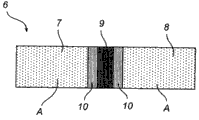
Fig. 2 is the diagrammatic depiction according to the weld seam of one embodiment of the present invention;
Fig. 3 is the diagrammatic depiction according to the weld seam of one embodiment of the present invention;
Fig. 4 a is the diagrammatic depiction according to the welding steel parts of one embodiment of the present invention;
Fig. 4 b is the diagrammatic depiction according to the welding steel parts of one embodiment of the present invention;
Fig. 5 is according to one embodiment of the present invention, is used to make the diagrammatic depiction of the method for steel ring;
Fig. 6 is the diagrammatic depiction according to the flanged bearing circle of one embodiment of the present invention;
Fig. 7 is according to one embodiment of the present invention, has the diagrammatic depiction of a part of the rolling bearing of race ring;
Fig. 8 a is the diagrammatic depiction according to the wheel bearing unit of one embodiment of the present invention;
Fig. 8 b is the diagrammatic depiction according to the wheel bearing unit of one embodiment of the present invention;
Fig. 9 is according to one embodiment of the present invention, is used to make the diagrammatic depiction of the method for lasso.
Embodiment
In Fig. 1, show according to the embodiment of the present invention, be used to make the schema of the method for steel parts.Described steel parts 6 comprise the first steel part 7 and the second steel part 8, and the carbon content of first and second steel part is up to 1.5 weight percents (wt%).Be heated to α/more than the γ transition temperature at least in part according to first step 1, the first steel part 7 of this method and the second steel part 8.In the step 2 that fetches, the first steel part 7 and the second steel part 8 engage by welding, and welding process occurs in the above temperature of α/γ transition temperature.In another subsequent step 3, apply cooling to avoid hardening effect.After cooling step 3, may wish further to handle steel parts 6 by using soft annealing step 4.This step will help other and handle (not shown), for example machining of steel parts 6 and distortion.In another subsequent step of this method, use process of setting 5, give the attribute that welding steel parts 6 are wished.
In Fig. 2, show the diagrammatic depiction of weld seam according to the embodiment of the present invention.The first steel part 7 and the second steel part 8 of steel parts 6 utilize weld seam 9 to engage.In this width of cloth figure,, simply represent weld seam with the essentially rectangular profile in order to simplify.But, should be appreciated that weld seam 9 can present that other are differently contoured, for example more as leg-of-mutton profile.Heat affected zone 10 is present near the weld seam 9, and the zone of influence A proximity thermal zone of influence 10 not.In this embodiment, the first and second steel parts 7,8 are made with identical steel, and have identical microtexture.In addition, in this embodiment, in the heating 1 of the method according to this invention, welding 2 with cool off after 3, but before any further treatment step is such as soft annealing 4, observe steel parts 6.Therefore, heat affected zone 10 has different slightly microtextures than the not zone of influence A of the first and second steel parts 7,8.Weld seam 9 with respect to the heat affected zone 10 of the first and second steel parts 7,8 and not zone of influence A have another kind of microtexture.
In Fig. 3, show diagrammatic depiction according to the weld seam of embodiment of the present invention.
The first steel part 7 and the second steel part 8 of steel parts 6 utilize weld seam 9 to engage.The contiguous weld seams 9 in heat affected zone 10, and the zone of influence A proximity thermal zone of influence 10 not.In this embodiment, the first and second steel parts 7,8 are made with identical steel and are had an identical microtexture.But, in this embodiment, except the step of in embodiment, implementing, after soft annealing 4 steps of the method according to this invention, observe steel parts 6 according to Fig. 2.Therefore, heat affected zone 10 and weld seam 9, the not zone of influence A with respect to the first and second steel parts 7,8 has identical or closely similar microtexture.
In Fig. 4 a, show diagrammatic depiction according to the welding steel parts of embodiment of the present invention.In this embodiment, the steel parts are the rings 11 that comprise weld seam 9.Weld seam 9 engages the first and second steel parts 7,8 of ring 11.Weld seam 9 utilizes the method according to first aspect present invention to form.
In Fig. 4 b, show diagrammatic depiction according to the welding steel parts of embodiment of the present invention.In this embodiment, the steel parts are the rings 11 that comprise two weld seams 9.Weld seam 9 engages the first and second steel parts 7,8 of ring 11.Weld seam 9 forms by adopting the method according to first aspect present invention.
In Fig. 5, show the diagrammatic depiction that is used to make the method for steel ring according to embodiment of the present invention.In this embodiment, lead 12 or steel billet 12 looped-shaped bending elements 13.Circular element 13 has the first steel part 7 and the second steel part 8.In following steps 14, the first and second steel parts 7,8 of circular element 13 utilize weld seam 9 to engage, and form steel ring 11 thus.Weld seam 9 forms by adopting the method according to first aspect present invention.
In Fig. 6, show diagrammatic depiction according to the spindle flange carrier ring of embodiment of the present invention.Spindle flange carrier ring 15 comprises steel ring 19 and flange 16.There are a plurality of holes in addition in described flange, and these holes can be used for flange is fixed to another structure (not shown).Steel ring 19 has the seat ring 18 that is used to receive rolling element such as ball or roller or receives the slip ring (not shown).Steel ring 11 further has the first steel part 7, and flange 16 has the second steel part 8 of utilizing weld seam 9 to engage.Weld seam 9 forms by adopting the method according to first aspect present invention.Be noted that this embodiment only states purpose for example, and the position of weld seam can be positioned at the elsewhere on the described welding assembly.In addition, other parts of bearings also can comprise according to weld seam of the present invention.In Fig. 7, show the diagrammatic depiction of the rolling bearing part of the neck collar that has according to the embodiment of the present invention.In this embodiment, rolling bearing 20 is spherical roller bearings.The lasso 21 that it comprises inner ring 22, outer ring 23, becomes a plurality of rollers 24 of two rows and be used for roller 24 is remained in position.Outer ring 23 has the first steel part 7 and the second steel part 8 of utilizing weld seam 9 to engage.Weld seam 9 forms by adopting the method according to first aspect present invention.Be noted that this embodiment only states purpose for example, and the position of weld seam can be chosen in the elsewhere in the welding assembly.In addition, other parts of bearings can comprise according to weld seam of the present invention.
In Fig. 8 a, show diagrammatic depiction according to the wheel bearing unit of embodiment of the present invention.Wheel bearing unit 26 comprises inner ring 22 or wheel hub 22, outer ring 23 and is plugged on therebetween a plurality of balls 25.Outer ring 23 can have wheel bearing unit is connected to for example flange (not shown) of steering knuckle (not shown) of car side accessory.Inner ring 22 has the first steel part 7.Purpose is that the flange 16 that is used for wheel is fitted into wheel bearing unit 26 has the second steel part 8.The first steel part 7 and the second steel part 8 utilize weld seam 9 according to the present invention to engage, and therefore flange 16 are joined to the inner ring 22 of wheel bearing unit 26.Weld seam 9 forms by adopting the method according to portion's first aspect present invention.
In this embodiment, rolling element is a ball, but also can be tapered roller or column roller.Described wheel bearing unit can also comprise other parts of bearings, such as lasso, sealing member, transmitter, encoder, lubricant etc.Be also to be understood that the present invention is not limited to the wheel bearing unit shown in Fig. 8 a, but also be applicable to other wheel hubs and wheel bearing design.Should also be noted that this embodiment only states purpose for example, and the position of weld seam can be positioned at the elsewhere on the wheel bearing unit.In addition, other wheel bearing parts can comprise according to weld seam of the present invention.
In Fig. 8 b, show diagrammatic depiction according to the wheel bearing unit of embodiment of the present invention.Wheel bearing unit 26 comprises inner ring 22 or wheel hub 22, outer ring 23 and a plurality of ball 25.In this embodiment, wheel bearing unit further has the independent inner ring 27 that is pressure fitted on the inner ring 22.Described independent inner ring 27 has the first steel part 7.Outer ring 23 can have and is used for wheel bearing unit is connected to for example flange (not shown) of steering knuckle (not shown) of car side accessory.It is the flange 16 that wheel is fitted into wheel bearing unit 26 that inner ring 22 has purpose.Inner ring 22 further has the second steel part 8.The first steel part 7 and the second steel part 8 are utilized according to weld seam of the present invention and are engaged, and therefore independent inner ring 27 are joined to the inner ring 22 of wheel bearing unit 26.Weld seam 9 forms by adopting the method according to first aspect present invention.
In this embodiment, rolling element is a ball, but also can be tapered roller or column roller.Described wheel bearing unit can also comprise other parts of bearings such as lasso, sealing member, transmitter, encoder, lubricant etc.Be also to be understood that the present invention is not limited to the wheel bearing unit shown in Fig. 8 b, but also be applicable to other wheel hubs and wheel bearing design.Should also be noted that this embodiment only states purpose for example, and position while welding can be in the elsewhere on the wheel bearing unit.In addition, other wheel bearing parts can comprise according to weld seam of the present invention.
Should be appreciated that, except these two kinds of embodiments of wheel bearing unit, also have other parts and the embodiment of this wheel bearing unit, wherein be suitable for.The manufacture method of different aspect, weldment or welding assembly according to the present invention.
In Fig. 9, show the diagrammatic depiction that is used for making the method for lasso according to embodiment of the present invention.In this embodiment, steel disc rolling become expectation profile 28.In following step, a plurality of pits 30 of punching press.The steel section bar 29 that produces bends to the ring (not shown).Steel section bar 29 has the first steel part 7 and the second steel part 8.In following steps 14, the first and second steel parts 7,8 of steel section bar utilize weld seam 9 to engage, and therefore produce lasso 31.Weld seam 9 forms by adopting the method according to first aspect present invention.Should be appreciated that, except this embodiment of lasso, also have other possible implementation, wherein be suitable for manufacture method, weldment or the welding assembly of different aspect according to the present invention.For example, can be by selling or little steel disc is welded to bigger punching press steel disc 29 and forms pit 30.
Claims (21)
1. one kind is used for the method that manufacturing comprises the steel parts (6,11) of first steel parts (7) and second steel parts (8), and the carbon content of described first and second steel parts (7,8) is up to 1.5 weight percents, and described method comprises:
-heating (1) described first steel parts (7) and heat described second steel parts (8) at least in part at least in part are to α/more than the γ transition temperature; With
-by described first steel parts of welded joint (2) (7) and described second steel parts (8), described welding occurs in the above temperature of α/γ transition temperature; With
-cooling (3) is to avoid hardening effect.
2. a method that is used to make steel parts (6) comprises the method for claim 1, further comprises soft annealing step (4).
3. a method that is used to make steel parts (6) comprises method as claimed in claim 2, further comprises the step of the described steel parts of sclerosis (5) (6,11).
4. a weld seam (9) comprising:
-carbon content is up to the steel of 1.5 weight percents;
-wherein said weld seam (9) has part perlite microtexture.
5. weld seam as claimed in claim 4 (9) further comprises the grain boundary carbide in 2 to the 4 volume percent scopes.
6. one kind is welded steel parts (6,11), comprising:
-the first steel parts (7);
-the second steel parts (8); With
-as claim 4 or 5 described weld seams (9), described weld seam (9) engages described first steel parts (7) and described second steel parts (8).
7. welding steel parts as claimed in claim 6 (6,11) is characterized in that, described first steel parts (7) are made with identical steel with described second steel parts (8).
8. welding steel parts as claimed in claim 6 (6,11) is characterized in that, described first steel parts (7) are made with different steel with described second steel parts (8).
9. welding steel parts as claimed in claim 6 (6,11) is characterized in that, described first steel parts (7) are the parts of the preceding identical steel parts of welding with described second steel parts (8).
10. welding steel parts as claimed in claim 6 (6,11) is characterized in that, described first steel parts (7) are the parts of the preceding different steel parts of welding with described second steel parts (8).
11. welding steel parts (6,11) have many as claim 4 or 5 described weld seams (9).
12. a weld seam (9) comprising:
-carbon content is up to the steel of 1.5 weight percents;
It is 0.2 to 3 micron carbide that-wherein said weld seam (9) has ferrite microtexture and mean sizes.
13. welding steel parts (6,11) comprising:
-the first steel parts (7);
-the second steel parts (8); With
-weld seam as claimed in claim 12 (9), described weld seam (9) engage described first steel parts (7) and described second steel parts (8).
14. welding steel parts as claimed in claim 13 (6,11) is characterized in that, described first steel parts (7) are made with identical steel with described second steel parts (8).
15. welding steel parts as claimed in claim 13 (6,11) is characterized in that, described first steel parts (7) are made with different steel with described second steel parts (8).
16. welding steel parts as claimed in claim 13 (6,11) is characterized in that, described first steel parts (7) are the parts of the preceding identical steel parts of welding with described second steel parts (8).
17. welding steel parts as claimed in claim 13 (6,11) is characterized in that, described first steel parts (7) are the parts of the preceding different steel parts of welding with described second steel parts (8).
18. welding steel parts (6,11) have many weld seams as claimed in claim 13 (9).
19. welding steel parts (6,11) have:
-heat affected zone (10);
-do not welded the not zone of influence (A) that influences; With
One of them has substantially the same microtexture with the described not zone of influence (A) at least for-weld seam (9), described weld seam (9) and described heat affected zone (10).
20. make the method for steel parts (6,11) according to claim 1, it is characterized in that described steel parts (6,11) are parts of bearings (11,15,20,22,26,27,31).
21. a parts of bearings (11,15,20,22,26,27,31) comprises as claim 4 or 5 described weld seams (9).
Priority Applications (1)
| Application Number | Priority Date | Filing Date | Title |
|---|---|---|---|
| CN201510302990.9A CN104911325A (en) | 2008-07-11 | 2009-07-10 | A method for manufacturing a steel component, a weld seam, a welded steel component, and a bearing component |
Applications Claiming Priority (3)
| Application Number | Priority Date | Filing Date | Title |
|---|---|---|---|
| SE0801673 | 2008-07-11 | ||
| SE0801673-5 | 2008-07-11 | ||
| PCT/SE2009/000365 WO2010005362A1 (en) | 2008-07-11 | 2009-07-10 | A method for manufacturing a steel component, a weld seam, a welded steel component, and a bearing component |
Related Child Applications (1)
| Application Number | Title | Priority Date | Filing Date |
|---|---|---|---|
| CN201510302990.9A Division CN104911325A (en) | 2008-07-11 | 2009-07-10 | A method for manufacturing a steel component, a weld seam, a welded steel component, and a bearing component |
Publications (1)
| Publication Number | Publication Date |
|---|---|
| CN102076874A true CN102076874A (en) | 2011-05-25 |
Family
ID=41507283
Family Applications (2)
| Application Number | Title | Priority Date | Filing Date |
|---|---|---|---|
| CN200980125484XA Pending CN102076874A (en) | 2008-07-11 | 2009-07-10 | A method for manufacturing a steel component, a weld seam, a welded steel component, and a bearing component |
| CN201510302990.9A Pending CN104911325A (en) | 2008-07-11 | 2009-07-10 | A method for manufacturing a steel component, a weld seam, a welded steel component, and a bearing component |
Family Applications After (1)
| Application Number | Title | Priority Date | Filing Date |
|---|---|---|---|
| CN201510302990.9A Pending CN104911325A (en) | 2008-07-11 | 2009-07-10 | A method for manufacturing a steel component, a weld seam, a welded steel component, and a bearing component |
Country Status (6)
| Country | Link |
|---|---|
| US (1) | US8820615B2 (en) |
| EP (1) | EP2310544B1 (en) |
| JP (2) | JP5753781B2 (en) |
| KR (1) | KR20110036705A (en) |
| CN (2) | CN102076874A (en) |
| WO (1) | WO2010005362A1 (en) |
Cited By (2)
| Publication number | Priority date | Publication date | Assignee | Title |
|---|---|---|---|---|
| CN110039267A (en) * | 2019-05-28 | 2019-07-23 | 聊城市东昌府区嘉泰轴承保持器厂 | A kind of wind-powered turntable bearing wear-resistant material ball retainer Integral welded technique |
| CN113604650A (en) * | 2021-07-12 | 2021-11-05 | 武汉新瑞达激光工程有限责任公司 | Laser strengthening and toughening treatment method for steel rail welded joint |
Families Citing this family (11)
| Publication number | Priority date | Publication date | Assignee | Title |
|---|---|---|---|---|
| DE102009056038B4 (en) | 2009-11-27 | 2022-05-19 | Schaeffler Technologies AG & Co. KG | Method for producing a bearing ring for a roller bearing, in particular for a thin ring bearing, and roller bearing, in particular thin ring bearing, comprising at least one bearing ring produced according to the method |
| EP2531312B1 (en) * | 2010-02-01 | 2014-04-02 | The Timken Company | Unified rolling and bending process for roller bearing cages |
| RU2563712C2 (en) * | 2010-09-28 | 2015-09-20 | Актиеболагет Скф | Bearing ring with flange and method of manufacture of similar bearing ring with flange |
| BR112014014946A2 (en) * | 2011-12-20 | 2017-06-13 | Skf Ab | method for manufacturing a steel component by arc butt welding and a component produced using the method |
| CN104094003A (en) * | 2012-02-14 | 2014-10-08 | Skf公司 | Method of producing cage, the cage and rolling bearing |
| CN104245215B (en) * | 2012-04-25 | 2016-08-24 | 新日铁住金株式会社 | Tack-weld |
| EP3096916A4 (en) | 2014-01-24 | 2017-11-22 | Electric Power Research Institute, Inc. | Stepped design weld joint preparation |
| CN105983814B (en) * | 2015-03-05 | 2017-11-07 | 宁夏巨能机器人系统有限公司 | A kind of manufacture craft of mechanical hand loading arm |
| FR3035695B1 (en) * | 2015-04-29 | 2017-11-24 | Skf Ab | SELF-ADJUSTABLE INSTRUMENT BEARING AND MECHANICAL SYSTEM EQUIPPED WITH SAID BEARING |
| JP6911153B2 (en) * | 2017-01-31 | 2021-07-28 | ヌブル インク | Methods and systems for welding copper using a blue laser |
| CN115415671A (en) * | 2022-09-14 | 2022-12-02 | 聊城产研创新发展有限公司 | laser-GMAW electric arc hybrid welding method for steel hub |
Family Cites Families (46)
| Publication number | Priority date | Publication date | Assignee | Title |
|---|---|---|---|---|
| US3531848A (en) * | 1966-01-10 | 1970-10-06 | Battelle Development Corp | Fabrication of integral structures |
| US3482296A (en) * | 1966-09-19 | 1969-12-09 | Gen Motors Corp | Method for the integrated welding and heat treating of hardenable parts |
| US3522644A (en) * | 1968-02-12 | 1970-08-04 | Torin Corp | Welding method for bearing races and other articles |
| US3506251A (en) * | 1969-06-16 | 1970-04-14 | Gen Motors Corp | Apparatus for the integrated welding and heat treating of hardenable parts |
| DE2123687C3 (en) * | 1971-05-13 | 1978-10-05 | Baustahlgewebe Gmbh, 4000 Duesseldorf | Continuous heat treatment process on rod-shaped, low-carbon structural steels |
| JPS5519297B2 (en) * | 1973-07-31 | 1980-05-24 | ||
| JPS53119236A (en) * | 1977-03-28 | 1978-10-18 | Sumitomo Metal Ind Ltd | Highly effecient welding method to obtain bond zone of high toughness |
| AU527097B2 (en) * | 1979-01-12 | 1983-02-17 | Nippon Steel Corporation | Artifically aged low yield to tensile strength ratio high strength steel sheet |
| JPS5669359A (en) * | 1979-10-16 | 1981-06-10 | Kobe Steel Ltd | Composite structure type high strength cold rolled steel sheet |
| US4397698A (en) * | 1979-11-06 | 1983-08-09 | Republic Steel Corporation | Method of making as-hot-rolled plate |
| US4501626A (en) * | 1980-10-17 | 1985-02-26 | Kabushiki Kaisha Kobe Seiko Sho | High strength steel plate and method for manufacturing same |
| US4437902A (en) * | 1981-10-19 | 1984-03-20 | Republic Steel Corporation | Batch-annealed dual-phase steel |
| JPS5877528A (en) * | 1981-10-31 | 1983-05-10 | Nippon Steel Corp | Manufacture of high tensile steel with superior toughness at low temperature |
| US4830686A (en) * | 1984-04-12 | 1989-05-16 | Kawasaki Steel Corporation | Low yield ratio high-strength annealed steel sheet having good ductility and resistance to secondary cold-work embrittlement |
| JPH01156428A (en) * | 1987-12-11 | 1989-06-20 | Kazuo Sato | Manufacture of steel belt |
| JP2815695B2 (en) * | 1990-10-31 | 1998-10-27 | 新日本製鐵株式会社 | Fluidized bed patenting method for high carbon steel wire |
| JPH0578754A (en) * | 1991-09-26 | 1993-03-30 | Nippon Steel Corp | Treatment of fluidized bed patenting for cr-containing high carbon steel wire |
| US5306361A (en) * | 1992-10-02 | 1994-04-26 | Besch Gordon O | Method for improving service life of rail welds by aluminothermic heat treatment |
| US5389164A (en) * | 1993-02-10 | 1995-02-14 | Nippon Steel Corporation | Production method of strong and tough thick steel plate |
| JPH09316598A (en) * | 1996-03-27 | 1997-12-09 | Nippon Steel Corp | Pearlitic rail, excellent in wear resistance and weldability, and its production |
| JPH11106825A (en) * | 1997-10-03 | 1999-04-20 | Sumitomo Metal Ind Ltd | Production of extra-low carbon nonheat treated type high workability electric resistance welded tube |
| JP3263348B2 (en) * | 1997-10-07 | 2002-03-04 | 住友鋼管株式会社 | Method of manufacturing non-heat treated high workability electric resistance welded steel pipe |
| JP3898809B2 (en) * | 1997-10-20 | 2007-03-28 | 新日本製鐵株式会社 | Method for producing ERW steel pipe having excellent formability and high ductility |
| KR100261664B1 (en) * | 1997-10-21 | 2000-07-15 | 이종훈 | Intercritical heat treatment process for toughness improvement of sa508 gr.3 steel |
| TW436597B (en) * | 1997-12-19 | 2001-05-28 | Exxon Production Research Co | Process components, containers, and pipes suitable for containign and transporting cryogenic temperature fluids |
| US6159312A (en) * | 1997-12-19 | 2000-12-12 | Exxonmobil Upstream Research Company | Ultra-high strength triple phase steels with excellent cryogenic temperature toughness |
| TW459053B (en) * | 1997-12-19 | 2001-10-11 | Exxon Production Research Co | Ultra-high strength dual phase steels with excellent cryogenic temperature toughness |
| US6537397B1 (en) * | 1998-08-18 | 2003-03-25 | Honda Giken Kogyo Kabushiki Kaisha | Process for producing Fe-based member having high young's modulus, and Fe-based member having high young's modulus and high toughness |
| WO2001064967A1 (en) * | 2000-02-29 | 2001-09-07 | Kawasaki Steel Corporation | High tensile cold-rolled steel sheet having excellent strain aging hardening properties |
| ATE315112T1 (en) * | 2000-04-07 | 2006-02-15 | Jfe Steel Corp | HOT, COLD ROLLED AND HOT-GALVANIZED STEEL PLATE WITH EXCELLENT STRETCH AGING BEHAVIOR |
| JP3399445B2 (en) * | 2000-05-25 | 2003-04-21 | 三菱電機株式会社 | Strip connection method in steel plate continuous processing line |
| AU776043B2 (en) * | 2000-11-28 | 2004-08-26 | Kawasaki Steel Corporation | Composite structure type high tensile strength steel plate, plated plate of composite structure type high tensile strength steel and method for their production |
| JP4051999B2 (en) * | 2001-06-19 | 2008-02-27 | Jfeスチール株式会社 | High tensile hot-rolled steel sheet excellent in shape freezing property and durability fatigue property after forming, and method for producing the same |
| KR100949694B1 (en) * | 2002-03-29 | 2010-03-29 | 제이에프이 스틸 가부시키가이샤 | Cold rolled steel sheet having ultrafine grain structure and method for producing the same |
| JP3844443B2 (en) * | 2002-04-12 | 2006-11-15 | 新日本製鐵株式会社 | Profile wire for reinforcing submarine optical fiber cable |
| JP4311912B2 (en) * | 2002-05-24 | 2009-08-12 | 株式会社小松製作所 | Manufacturing method of crawler belt bush |
| JP3863818B2 (en) * | 2002-07-10 | 2006-12-27 | 新日本製鐵株式会社 | Low yield ratio steel pipe |
| JP4352951B2 (en) * | 2004-03-16 | 2009-10-28 | 住友金属工業株式会社 | Method for producing hot-rolled steel sheet made of high carbon steel or high carbon alloy steel |
| US7588837B2 (en) * | 2005-04-29 | 2009-09-15 | The Timken Company | Welding together low and high carbon steels |
| US20070007297A1 (en) * | 2005-05-16 | 2007-01-11 | Li Kwong F | Sealable container |
| JP2007263299A (en) * | 2006-03-29 | 2007-10-11 | Ntn Corp | Manufacturing method of bearing device for wheel |
| JP5142068B2 (en) * | 2006-05-17 | 2013-02-13 | 日産自動車株式会社 | High strength steel plate for resistance spot welding and joining method thereof |
| JP4969221B2 (en) * | 2006-11-28 | 2012-07-04 | 三菱重工業株式会社 | Deterioration part reproduction method, degradation part reproduction device |
| JP4995111B2 (en) * | 2007-02-09 | 2012-08-08 | 新日本製鐵株式会社 | Ferritic heat-resistant steel and heat-resistant structure with excellent creep characteristics in weld heat-affected zone |
| JP4995130B2 (en) * | 2007-03-29 | 2012-08-08 | 新日本製鐵株式会社 | Ferritic heat-resistant steel and heat-resistant structure with excellent creep characteristics in weld heat-affected zone |
| JP4916365B2 (en) * | 2007-04-05 | 2012-04-11 | 株式会社小松製作所 | Crawler bush |
-
2009
- 2009-07-10 JP JP2011517377A patent/JP5753781B2/en not_active Expired - Fee Related
- 2009-07-10 KR KR1020107028280A patent/KR20110036705A/en not_active Application Discontinuation
- 2009-07-10 EP EP09794717.0A patent/EP2310544B1/en active Active
- 2009-07-10 WO PCT/SE2009/000365 patent/WO2010005362A1/en active Application Filing
- 2009-07-10 CN CN200980125484XA patent/CN102076874A/en active Pending
- 2009-07-10 US US12/997,931 patent/US8820615B2/en active Active
- 2009-07-10 CN CN201510302990.9A patent/CN104911325A/en active Pending
-
2014
- 2014-04-24 JP JP2014090136A patent/JP2014144486A/en active Pending
Cited By (3)
| Publication number | Priority date | Publication date | Assignee | Title |
|---|---|---|---|---|
| CN110039267A (en) * | 2019-05-28 | 2019-07-23 | 聊城市东昌府区嘉泰轴承保持器厂 | A kind of wind-powered turntable bearing wear-resistant material ball retainer Integral welded technique |
| CN113604650A (en) * | 2021-07-12 | 2021-11-05 | 武汉新瑞达激光工程有限责任公司 | Laser strengthening and toughening treatment method for steel rail welded joint |
| CN113604650B (en) * | 2021-07-12 | 2023-02-28 | 武汉新瑞达激光工程有限责任公司 | Laser strengthening and toughening treatment method for steel rail welding joint |
Also Published As
| Publication number | Publication date |
|---|---|
| EP2310544B1 (en) | 2018-10-17 |
| KR20110036705A (en) | 2011-04-08 |
| JP2011527635A (en) | 2011-11-04 |
| WO2010005362A1 (en) | 2010-01-14 |
| EP2310544A4 (en) | 2016-12-28 |
| US20110158572A1 (en) | 2011-06-30 |
| US8820615B2 (en) | 2014-09-02 |
| CN104911325A (en) | 2015-09-16 |
| EP2310544A1 (en) | 2011-04-20 |
| JP2014144486A (en) | 2014-08-14 |
| JP5753781B2 (en) | 2015-07-22 |
Similar Documents
| Publication | Publication Date | Title |
|---|---|---|
| CN102076874A (en) | A method for manufacturing a steel component, a weld seam, a welded steel component, and a bearing component | |
| CN104245987B (en) | Cold working steel for mechanical structure and manufacture method thereof | |
| KR102077408B1 (en) | Friction welding method | |
| RU2591907C2 (en) | Method of making steel component by butt fusion welding and component made using said method | |
| JP5700174B2 (en) | Induction hardening steel | |
| CN103442837B (en) | The manufacture method of clad steel parts | |
| CN101722385A (en) | Flux-cored wire and method for welding hot-rolled back-up roll by same | |
| JPWO2006033316A1 (en) | Heat treatment method in press-fitting and joining structure by the method | |
| CN100494713C (en) | Bearing unit with brazed or soldered connection | |
| CN110684924B (en) | X100 steel grade tee pipe fitting material manufactured by electric melting additive and using method | |
| CN105256238B (en) | A kind of preparation method of auto parts low-carbon martensite non-hardened and tempered steel | |
| US20140003752A1 (en) | Steel and component | |
| JP4854754B2 (en) | Liquid phase diffusion bonding method for machine parts | |
| CN104073712B (en) | High-carbon vanadium titanium grey cast iron and manufacturing method thereof, as well as vehicle brake disk and manufacturing method thereof | |
| US20150043854A1 (en) | Method and Component | |
| CN103069017B (en) | Method of making a bearing ring, a bearing ring and a bearing | |
| CN114959464B (en) | Pin bush for crawler belt and preparation method thereof | |
| Hamill | Weld techniques give powder metal a different dimension | |
| JP5279002B2 (en) | Method for manufacturing roller shell of lower traveling body of construction machine | |
| EP2814994B1 (en) | A bearing steel composition | |
| JP2002263853A (en) | Method for assembling and welding high-temperature mechanical component | |
| Müllerschön | New Laser Applications in Powertrain Production | |
| CN103659016A (en) | Making method of axis neck of 9-12% Cr steel turbine rotor and axis neck produced by the method |
Legal Events
| Date | Code | Title | Description |
|---|---|---|---|
| C06 | Publication | ||
| PB01 | Publication | ||
| C10 | Entry into substantive examination | ||
| SE01 | Entry into force of request for substantive examination | ||
| C12 | Rejection of a patent application after its publication | ||
| RJ01 | Rejection of invention patent application after publication |
Application publication date: 20110525 |