CN101999045A - Device for sealing a hydraulic piston - Google Patents
Device for sealing a hydraulic piston Download PDFInfo
- Publication number
- CN101999045A CN101999045A CN2009801120313A CN200980112031A CN101999045A CN 101999045 A CN101999045 A CN 101999045A CN 2009801120313 A CN2009801120313 A CN 2009801120313A CN 200980112031 A CN200980112031 A CN 200980112031A CN 101999045 A CN101999045 A CN 101999045A
- Authority
- CN
- China
- Prior art keywords
- sealing
- groove
- lip
- lip packing
- sealed
- Prior art date
- Legal status (The legal status is an assumption and is not a legal conclusion. Google has not performed a legal analysis and makes no representation as to the accuracy of the status listed.)
- Pending
Links
Images


Classifications
-
- F—MECHANICAL ENGINEERING; LIGHTING; HEATING; WEAPONS; BLASTING
- F16—ENGINEERING ELEMENTS AND UNITS; GENERAL MEASURES FOR PRODUCING AND MAINTAINING EFFECTIVE FUNCTIONING OF MACHINES OR INSTALLATIONS; THERMAL INSULATION IN GENERAL
- F16J—PISTONS; CYLINDERS; SEALINGS
- F16J15/00—Sealings
- F16J15/16—Sealings between relatively-moving surfaces
- F16J15/32—Sealings between relatively-moving surfaces with elastic sealings, e.g. O-rings
- F16J15/3204—Sealings between relatively-moving surfaces with elastic sealings, e.g. O-rings with at least one lip
- F16J15/3232—Sealings between relatively-moving surfaces with elastic sealings, e.g. O-rings with at least one lip having two or more lips
- F16J15/3236—Sealings between relatively-moving surfaces with elastic sealings, e.g. O-rings with at least one lip having two or more lips with at least one lip for each surface, e.g. U-cup packings
-
- F—MECHANICAL ENGINEERING; LIGHTING; HEATING; WEAPONS; BLASTING
- F16—ENGINEERING ELEMENTS AND UNITS; GENERAL MEASURES FOR PRODUCING AND MAINTAINING EFFECTIVE FUNCTIONING OF MACHINES OR INSTALLATIONS; THERMAL INSULATION IN GENERAL
- F16J—PISTONS; CYLINDERS; SEALINGS
- F16J15/00—Sealings
- F16J15/56—Other sealings for reciprocating rods
-
- F—MECHANICAL ENGINEERING; LIGHTING; HEATING; WEAPONS; BLASTING
- F15—FLUID-PRESSURE ACTUATORS; HYDRAULICS OR PNEUMATICS IN GENERAL
- F15B—SYSTEMS ACTING BY MEANS OF FLUIDS IN GENERAL; FLUID-PRESSURE ACTUATORS, e.g. SERVOMOTORS; DETAILS OF FLUID-PRESSURE SYSTEMS, NOT OTHERWISE PROVIDED FOR
- F15B15/00—Fluid-actuated devices for displacing a member from one position to another; Gearing associated therewith
- F15B15/08—Characterised by the construction of the motor unit
- F15B15/14—Characterised by the construction of the motor unit of the straight-cylinder type
- F15B15/1423—Component parts; Constructional details
- F15B15/1447—Pistons; Piston to piston rod assemblies
- F15B15/1452—Piston sealings
Abstract
The invention relates to a device for sealing a hydraulic piston (1) in a hydraulic cylinder, comprising at least one sealing groove (2) disposed in the hydraulic piston (1), und a lip seal (3) inserted into the sealing groove (2), said lip seal comprising a sealing lip (4) facing a fluid side (5) and a seal back (6) facing an air side (7). The invention is characterized in that means are provided for improving the sealing action of the lip seal (3) at least by forming a sealing groove (2) on at least one sealing groove side wall (11, 12) and/or on the sealing groove base (14).
Description
Technical field
The present invention relates to be used for the equipment of the hydraulic piston of sealing fluid cylinder pressure, it comprises that at least one is arranged in the sealed groove in the hydraulic piston, and the lip packing in the insertion sealed groove, described lip packing comprises the sealed lip of facing fluid side and towards the Sealing back of air side.
Background technique
Known and used this equipment, for example, in hydraulic brake and clutch system.Two water-tight equipments generally are arranged on the hydraulic piston of hydraulic brake system, are positioned at main sealing and secondary seal on the piston pressure side, its with hydraulic system with respect to aeroseal.
Because lip packing is with respect to the friction of casing wall, when piston motion, especially advance and return movement between change procedure in, heeling moment acts on the lip packing.So, Sealing can the seal groove base from the location rise, thereby forms passage on the internal diameter of Sealing, and air can enter cylinder chamber.Under the situation of the secondary seal that is used for hydraulic brake, air enters the hydraulic brake system, and the result is that the pressure spot of break can move, thereby influences proportional conveying unfriendly.Yet, air even can cause the inefficacy of brake system.
In order to reduce the risk that Sealing rises from bottom portion of groove, for example, DE 2263012A discloses the two-part that sealed groove are divided into different axial lengths, within it directly is attached to each other.Long part has cylindrical shape.In short part, the bottom circular diameter begins to increase from column part.Lip packing is inserted in the sealed groove, and the internal freedom end of this lip packing is against bottom portion of groove and its therefore more important place compression of quilt of short part.Free-ended weight contracts and causes friction bigger between the inwall of Sealing and oil hydraulic cylinder, yet, operation like this, for example, especially proportional transmission of hydraulic brake can be undermined.
Summary of the invention
Therefore the objective of the invention is to produce the equipment of the hydraulic piston that is used for sealing reliably aforementioned type, wherein, reduce the risk that Sealing tilts, and need not to change in fact the friction between Sealing and the oil hydraulic cylinder simultaneously.
This target realizes like this, is provided for improving the device of the seal action of this lip packing, and this device improves the seal action of this lip packing at least by shaping sealing groove at least one sealed groove sidewall and/or on the seal groove base.
The device that is used to improve seal action according to the present invention mainly is used to the transmission side of hydraulic system, for example in the manual control element of hydraulic brake or clutch system or in the conveyer with the pin operation.Yet the present invention can also be used on the receiver side of hydraulic system, for example on the clutch of hydraulic actuating or on the brake master cylinder in braking system.
The enhanced seal effect means that oil hydraulic cylinder and hydraulic piston can be correspondingly littler Yu compacter designs.Therefore oil hydraulic cylinder can be located in, for example, and radially and on the manual control element of axial design.
In an embodiment who is used for improving seal action, the diameter of selected sealed groove is greater than the nominal diameter of lip packing.This makes Sealing expand more and has increased pretensioning.Simultaneously, the risk of inclination reduces along with the expansion of diameter difference that increases and the Sealing that increases thus.At this, the diameter of sealed groove is in big 0.1% to 10% the scope of nominal diameter than Sealing.Be used for the 2%-3% that diameter difference under the standard hydraulic piston situation of motorcycle is preferably about nominal diameter.
In another embodiment of the present invention, lip packing is axially constrained in the sealed groove, for example determine the size of this recess width or pass through packing ring that by corresponding for example after inserting Sealing in the sealed groove, packing ring can be pushed into against the Sealing back.This is used to reduce the axial clearance of Sealing, is not the inclination spacing.
In another suitable development of the present invention, lip packing is bonded to the sealed groove sidewall with being adhered, is preferably located on the air side.This cohesive bond prevents that Sealing from tilting and air enters hydraulic system.The tackiness agent of permanent elasticity, anti-oil or anti-brake fluid can preferably be used as tackiness agent.
In advantageous development of the present invention, seal groove base tilts, and preferably has than in the little degree of depth of air side in fluid side.This causes tension force bigger on a side of Sealing and therefore better sealing.In addition, the opposite side of Sealing is against the sealed groove sidewall, thereby Sealing no longer tilts.At this, the angle between the longitudinal axis of seal groove base and hydraulic piston preferably between 0.1 ° and 6 °, especially is approximately 2 °.
Further favourable development of the present invention proposes in the dependent claims, can use the described measure that is used to improve seal action with independent and any compound mode.
Description of drawings
With reference to accompanying drawing, below illustrate in greater detail various exemplary embodiment of the present invention, wherein:
Fig. 1 shows the first embodiment of the present invention of the nominal diameter of the sealed groove with amplification,
Fig. 2 shows second development of the present invention with axial gasket,
Fig. 3 shows the 3rd development of the present invention at the Sealing back with adhesion ground combination,
Fig. 4 shows the 4th development of the present invention of the sealed groove sidewall with inclination,
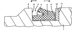
Fig. 5 shows the 5th development of the present invention of the seal groove base with inclination,
Fig. 6 shows the sectional view that has according to the brake control element of the hydraulic piston of Fig. 5, and
Fig. 7 shows the longitudinal cross-section of passing the hydraulic piston among Fig. 6.
Embodiment
Fig. 1 shows the details of the hydraulic braking piston 1 in the zone that is in secondary seal equipment, and this secondary seal equipment comprises sealed groove 2 and the lip packing 3 that inserts wherein, and this lip packing 3 comprises sealed lip 4 and Sealing back 6.Sealed lip 4 points to the fluid or the oily side 5 of piston 1 in this case, and Sealing back 6 is towards the air side 7 of piston.
Sealed groove 2 has the outside diameter bigger than the nominal diameter 8 of the lip packing 3 that is illustrated by the broken lines.In example, for the nominal diameter of the piston that is approximately 5.5mm, this difference D is approximately 0.15mm, and it is corresponding to about 2.5% of this nominal diameter.This has increased sealed lip 4 and has protruded the scope that surpasses groove top edge 9, and the compression that is in the lip packing 3 in the assembling condition thus, for example, according to desirable additional compression, the difference in diameter D of scope from 0.1% to 10% or bigger nominal diameter is feasible.
In embodiments of the invention shown in Figure 2, packing ring 10 is inserted on the air side 7 between the Sealing back 6 and sealed groove sidewall 11 of lip packing 3, and this packing ring 10 has reduced the axial clearance of lip packing 3.This means on the both sides of lip packing 3, between Sealing 3 and each sealed groove sidewall 11,12, only keep small interval, thereby the inclination of Sealing 3 no longer may.Packing ring 10 is preferably made by elastic material, thereby packing ring 10 can be pushed in the sealed groove 2 after inserting Sealing.
Fig. 3 shows the third embodiment of the present invention, and wherein, Sealing back 6 is bonded to air side sealed groove sidewall 11 with adhering.Herein tackiness agent 13 preferably permanent elasticity and be anti-oil or anti-brake fluid.
In the embodiment of distortion shown in Figure 4, the sealed groove sidewall 12 that is positioned on the fluid side 5 tilts, and recess width reduces towards bottom portion of groove 14.Lip packing 3 utilizes Sealing back 6 against air side sealed groove sidewall 11 in fact thus, has reduced the risk that tilts thus.
The embodiment of the distortion of representing among Fig. 5 has the seal groove base 14 of inclination, its from fluid side sealed groove sidewall 12 towards air side sealed groove sidewall 11, that is to say linear earth tilt on the whole width of sealed groove 2, thus in the depth of groove on the fluid side 5 less than the depth of groove on air side 7.In this case, lip packing 3 is arranged in sealed groove 2 with the angle that tilts.This means that Sealing 3 quilts more are compressed in the zone of sealed lip 4 in the important place, have increased the contact pressure of sealed lip 4 with respect to casing wall (not shown) on every side thus.Replacedly, seal groove base 14 also comprises one or more steps, and lip packing is with the angle that the tilts edge against this step.
Therefore, herein, only be that fluid side Sealing part rather than whole Sealing are located by further radially outward, this fluid side Sealing part mainly works to sealing.This means that outside seal lip 4 is also relatively low with respect to whole contact pressures of cylinder, and mainly corresponding to the contact pressure of the Sealing of traditional design and layout.
Because the inclination of bottom portion of groove 14, Sealing is positioned at " position of inclination ", thereby in fact can not take place further to tilt.In addition, owing to the friction that occurs on the inclined notches formed bottom, in fact got rid of vertically moving of Sealing.When heeling moment acted on the outside seal lip 4, the position that has tilted of Sealing had prevented any further inclination, thereby inner, air side sealing surface can not rise.
In addition, the Sealing back 6 on the air side can with its all or the location against sealed groove sidewall 11, thereby the risk that Sealing 3 tilts is further reduced.
Herein, the angle A between the longitudinal axis 15 of seal groove base 14 and oil hydraulic cylinder is preferably between 0.1 ° and 6 °.
In a preferred embodiment, for the sealed groove length of about 4.5mm, be 0.15mm along the height difference H of seal groove base 14.Angle A is approximately 2 ° herein.
Embodiment shown in Fig. 5 also has and is easier to the advantage of assembling and processing.
Fig. 6 shows the manual control element 16 of the hydraulic braking sytem of motorcycle as an example.Manual control element 16 comprises oil hydraulic cylinder 17, and wherein brake piston 1 is supported movably.Brake piston 1 is connected to the handle 20 of control unit 16 via plunger rod 18, and this plunger rod 18 is engaged in the spherical notch 19 on the air side 5 on the brake piston 1, thereby the compression movement of handle 20 has produced the motion of brake piston 1.Brake piston 1 only returns by the Returnning spring 21 on the oily side 5 of oil hydraulic cylinder 17 with handle 20.Yet manual control element 16 can also be any other project organization, so the present invention is in no way limited to this example.
Brake piston 1 comprises the device that is used to improve seal action according to Fig. 5.More details as shown in Figure 7, sealed groove 2 have the seal groove base 14 that extends to the longitudinal axis 15 of piston 1 with the angle of inclination, and the depth of groove on the oily side 5 is less than the depth of groove on the air side 7.In example, the angle A between bottom portion of groove 14 and the longitudinal axis 15 is approximately 2 ° ideally.
Claims (8)
1. equipment that is used for the hydraulic piston (1) of sealing fluid cylinder pressure, it comprises that at least one is arranged in the sealed groove (2) in this hydraulic piston (1), and the lip packing (3) in the insertion sealing groove (2), described lip packing comprises the sealed lip (4) of facing fluid side (5) and towards the Sealing back (6) of air side (7), it is characterized in that, be provided for improving the device of the seal action of this lip packing (3), this device is at least by going up at least one sealed groove sidewall (11,12) and/or going up shaping sealing groove (2) in seal groove base (14) and improve the seal action of this lip packing (3).
2. equipment according to claim 1, it is characterized in that, diameter poor (D) between the nominal diameter (8) of the diameter of sealing groove (2) and this lip packing (3) is approximately 0.1% to 10% of this nominal diameter (8), is preferably about 2% to 3% of this nominal diameter (8).
3. equipment according to claim 1 and 2 is characterized in that, this lip packing (3) is for example axially constrained in the sealing groove (2) by the size of corresponding definite this recess width or by packing ring (10).
4. according to the described equipment of one of claim 1 to 3, it is characterized in that this lip packing (3) is preferably gone up in this air side (7) and is bonded to sealed groove sidewall (11) with adhering.
5. according to the described equipment of one of claim 1 to 4, it is characterized in that the sealed groove sidewall (12) on this fluid side (5) tilts particularly, and the sealing recess width preferably reduces towards this bottom portion of groove (14).
6. according to the described equipment of one of claim 1 to 5, it is characterized in that sealing bottom portion of groove (14) tilts, and preferably have than in the little degree of depth of this air side in this fluid side.
7. equipment according to claim 6 is characterized in that, the angle (A) between the longitudinal axis (15) of sealing bottom portion of groove (14) and this hydraulic piston (1) is between 0.1 ° and 6 °.
8. equipment according to claim 7 is characterized in that, the angle (A) between the longitudinal axis (15) of sealing bottom portion of groove (14) and this hydraulic piston (1) is approximately 2 °.
Applications Claiming Priority (3)
| Application Number | Priority Date | Filing Date | Title |
|---|---|---|---|
| DE102008017035.6 | 2008-04-03 | ||
| DE102008017035A DE102008017035A1 (en) | 2008-04-03 | 2008-04-03 | Device for sealing a hydraulic piston |
| PCT/EP2009/002243 WO2009121523A1 (en) | 2008-04-03 | 2009-03-27 | Device for sealing a hydraulic piston |
Publications (1)
| Publication Number | Publication Date |
|---|---|
| CN101999045A true CN101999045A (en) | 2011-03-30 |
Family
ID=40957591
Family Applications (1)
| Application Number | Title | Priority Date | Filing Date |
|---|---|---|---|
| CN2009801120313A Pending CN101999045A (en) | 2008-04-03 | 2009-03-27 | Device for sealing a hydraulic piston |
Country Status (6)
| Country | Link |
|---|---|
| US (1) | US20110072963A1 (en) |
| EP (1) | EP2271847B1 (en) |
| CN (1) | CN101999045A (en) |
| DE (1) | DE102008017035A1 (en) |
| ES (1) | ES2737854T3 (en) |
| WO (1) | WO2009121523A1 (en) |
Families Citing this family (3)
| Publication number | Priority date | Publication date | Assignee | Title |
|---|---|---|---|---|
| DE102011055645A1 (en) * | 2011-11-23 | 2013-05-23 | Gustav Magenwirth Gmbh & Co. Kg | master cylinder |
| CN104110498A (en) * | 2014-07-10 | 2014-10-22 | 安徽京鸿密封件技术有限公司 | Y-type seal ring |
| EP3543568B1 (en) * | 2018-03-19 | 2021-01-06 | Carl Freudenberg KG | Sealing ring, sealing arrangement and use of a sealing arrangement |
Family Cites Families (18)
| Publication number | Priority date | Publication date | Assignee | Title |
|---|---|---|---|---|
| US1356703A (en) * | 1918-05-14 | 1920-10-26 | Evans Charles Sumner | Puzzle |
| US2293564A (en) * | 1940-04-29 | 1942-08-18 | Wagner Electric Corp | Sealing means |
| US2686402A (en) * | 1948-12-31 | 1954-08-17 | Charles A Samuel | Hydraulic brake wheel cylinder piston |
| US2687335A (en) * | 1950-03-15 | 1954-08-24 | Hulie E Bowerman | Piston |
| DE1264889B (en) * | 1963-06-05 | 1968-03-28 | Teves Gmbh Alfred | Actuating cylinder for disc brakes |
| GB1356703A (en) * | 1972-01-06 | 1974-06-12 | Girling Ltd | Pistons |
| DE7900776U1 (en) * | 1978-01-13 | 1979-07-05 | D.B.A. Bendix Lockheed Air Equipement S.A., Clichy, Hauts-De-Seine (Frankreich) | Sealing device |
| US4305595A (en) * | 1980-04-30 | 1981-12-15 | Hydril Company | Composite seal |
| DE3048397A1 (en) * | 1980-12-22 | 1982-07-01 | Stoll, Kurt, Dipl.-Ing., 7300 Esslingen | "FOR PNEUMATICALLY OR HYDRAULICALLY OPERATED WORK UNITS, E.g. |
| DE4104070A1 (en) * | 1991-02-11 | 1992-08-13 | Teves Gmbh Alfred | Brake cylinder seal - has reduced brake ring contact area on piston |
| US5833245A (en) * | 1997-05-19 | 1998-11-10 | Gallagher; Stephen F. | Elastomer ring seal for pressurized fluids |
| US6334619B1 (en) * | 1998-05-20 | 2002-01-01 | Kalsi Engineering, Inc. | Hydrodynamic packing assembly |
| US5960700A (en) * | 1998-08-26 | 1999-10-05 | National-Oilwell, L.P. | Replaceable mud pump piston seal |
| JP4357660B2 (en) * | 1999-08-27 | 2009-11-04 | 本田技研工業株式会社 | Master cylinder device for vehicle |
| JP4318618B2 (en) * | 2004-09-30 | 2009-08-26 | 日信工業株式会社 | Hydraulic vehicle disc brake |
| JP2006349005A (en) * | 2005-06-14 | 2006-12-28 | Farukomu:Kk | Pressure cylinder equipment |
| KR101024972B1 (en) * | 2005-12-06 | 2011-03-25 | 유니마테크 가부시키가이샤 | Rod sealing system |
| DE102007017512A1 (en) * | 2006-05-03 | 2007-12-13 | Continental Teves Ag & Co. Ohg | caliper |
-
2008
- 2008-04-03 DE DE102008017035A patent/DE102008017035A1/en active Pending
-
2009
- 2009-03-27 EP EP09728729.6A patent/EP2271847B1/en active Active
- 2009-03-27 ES ES09728729T patent/ES2737854T3/en active Active
- 2009-03-27 CN CN2009801120313A patent/CN101999045A/en active Pending
- 2009-03-27 WO PCT/EP2009/002243 patent/WO2009121523A1/en active Application Filing
-
2010
- 2010-10-01 US US12/896,367 patent/US20110072963A1/en not_active Abandoned
Also Published As
| Publication number | Publication date |
|---|---|
| EP2271847B1 (en) | 2019-05-08 |
| WO2009121523A1 (en) | 2009-10-08 |
| US20110072963A1 (en) | 2011-03-31 |
| ES2737854T3 (en) | 2020-01-16 |
| EP2271847A1 (en) | 2011-01-12 |
| DE102008017035A1 (en) | 2009-10-08 |
Similar Documents
| Publication | Publication Date | Title |
|---|---|---|
| US7963113B2 (en) | Cylinder device | |
| CN102155513B (en) | Fluid damper with internal compression spring | |
| EP1911646A3 (en) | Vehicle brake hydraulic pressure control unit | |
| CN101482176B (en) | Piston rod connecting device | |
| US6739842B2 (en) | Pump | |
| CN102252093A (en) | Fluid pressure apparatus | |
| CN101999045A (en) | Device for sealing a hydraulic piston | |
| CN108779787A (en) | Hydraulic cylinder | |
| US20060213734A1 (en) | Double tube hydraulic shock absorber | |
| EP1911647A3 (en) | Vehicle brake hydraulic pressure control unit and method for producing the same | |
| EP0896174A3 (en) | Piston ring arrangement for shock absorber | |
| CN101815864B (en) | Piston pump for conveying a fluid and associated braking system | |
| CN106837897A (en) | Pressure cylinder with motion sleeve, especially active cylinder | |
| CN101504074A (en) | Hydraulic cylinder | |
| JP5211999B2 (en) | Cup seal | |
| CN100384668C (en) | Master cylinder, especially for a regulated brake system | |
| CN102312948A (en) | The disk type braker pusher plate is to the adhesive attachment of diaphragm | |
| JP2004278639A (en) | Pulsation absorber and clutch master cylinder | |
| WO2014001876A1 (en) | Braking device of a trailer | |
| JP4723488B2 (en) | Piston type accumulator | |
| EP1184246A3 (en) | Master cylinder | |
| CN206429569U (en) | High pressure resistant clutch slave cylinder | |
| US6854271B2 (en) | Hydraulic actuation device in motor vehicles | |
| WO2006000907A1 (en) | Hydraulic actuators | |
| US20080185247A1 (en) | Sealing structure for self leveling damper utilizing quadrangular-sectioned o-ring |
Legal Events
| Date | Code | Title | Description |
|---|---|---|---|
| C06 | Publication | ||
| PB01 | Publication | ||
| C10 | Entry into substantive examination | ||
| SE01 | Entry into force of request for substantive examination | ||
| C02 | Deemed withdrawal of patent application after publication (patent law 2001) | ||
| WD01 | Invention patent application deemed withdrawn after publication |
Application publication date: 20110330 |