CN101936851B - Specimen clamp for measuring tensile strength of rock by splitting method - Google Patents
Specimen clamp for measuring tensile strength of rock by splitting method Download PDFInfo
- Publication number
- CN101936851B CN101936851B CN2010102705329A CN201010270532A CN101936851B CN 101936851 B CN101936851 B CN 101936851B CN 2010102705329 A CN2010102705329 A CN 2010102705329A CN 201010270532 A CN201010270532 A CN 201010270532A CN 101936851 B CN101936851 B CN 101936851B
- Authority
- CN
- China
- Prior art keywords
- filler strip
- bearing seat
- connecting rod
- cushion block
- pin
- Prior art date
- Legal status (The legal status is an assumption and is not a legal conclusion. Google has not performed a legal analysis and makes no representation as to the accuracy of the status listed.)
- Expired - Fee Related
Links
Images


Abstract
The invention discloses a specimen clamp for measuring the tensile strength of rocks by a splitting method, which comprises an installing frame, centralizing frames, connecting rods, bearing seats, a lower cushion strip slot, cushion block guiding slots, pin guiding slots and an upper cushion strip slot, and is characterized in that the structure of the specimen clamp is right-and-left symmetrical, a first centralizing frame is connected with the installing frame through a first bearing seat and a second bearing seat, a second centralizing frame is connected with the installing frame through a third bearing seat and a fourth bearing seat, one end of a first connecting rod is connected with the first centralizing frame, the other end of the first connecting rod is connected with a pin, one end of a second connecting rod is connected with the second centralizing frame, the other end of the second connecting rod is connected with the pin, the tail ends of the first connecting rod and the second connecting rod are clamped at one side of the pin guiding slots through the pins, cushion blocks are clamped in a first cushion block guiding slot and a second cushion block guiding slot, and an upper cushion strip is assembled in the upper cushion strip slot. The invention has safe, simple and convenient operation and high positioning precision, ensures that the strained condition of a rock specimen strictly conforms to requirements in the testing process to obtain high-precision test data.
Description
Technical field
The present invention relates to the rock mechanics experiment technical field, more specifically relate to the piece fixture that a kind of split the law is measured Tensile Strength of Rock, be applicable to accurate setting circle cylinder rock sample in the process of the test.
Background technology
In the rock mechanics engineering practice, stable structure body inside does not allow to occur tension usually, but practice shows that pulling open bad is one of main failure mode of engineering rock mass, and the performances such as the relative resistance to compression of tensile property of rock are low-down, and tensile strength therefore how as far as possible to measure rock has exactly caused the extensive concern of domestic and international project circle.
The method of measuring Tensile Strength of Rock has two kinds of direct method and indirect methods, because there are a large amount of difficult problems in direct tensile test in methods such as test material preparation and experimental techniques, domestic and international project circle at present adopts indirect pulling method.In indirect pulling method, degree of recognition the highest, most widely used general and the operation the easiest method be " split the law ", this method is proposed based on theory of elastic mechanics by a Brazilian slip-stick artist the earliest, therefore claim again " Brazilian split the law " that its test method makes test specimen destroy the tensile strength of indirect determination rock along diametric(al) for apply a pair of linear load on right cylinder test specimen diametric(al).
In the rock mechanics experiment relevant criterion and rules of China, all recommend to adopt split the law to measure the tensile strength of rock, as " Standard for test methods of engineering rock masses GB/T50266-99 ", " Hydraulic and Hydro-Power Engineering rock test rules SL264-2001 " and " highway engineering rock test rules JTG E41-2005 ".The method of operating of stipulating in the above-mentioned document is: draw two in the side of test specimen along axis direction by the two ends of test specimen diameter and load baseline, two filler strips are fixed along loading baseline, place testing machine bearing plate center to adjust spheric seat test specimen, make the even stressed acting force of test specimen by the determined plane of two filler strips.But all do not provide the device of loading baseline in location in the test operation in above-mentioned standard and the rules, filler strip is difficult on the worktable of testing machine accurately centering in the actual mechanical process, often need a hand steered rock sample of laboratory technician, another laboratory technician's service test machine, complex operation and the very big potential safety hazard of existence, key issue is easily to cause splitting surface to depart to cause the test figure accuracy.
At this problem, several rock cleavage test fixtures have been provided in the pertinent literature both at home and abroad.
" discussion of rock tensile test split the law measuring technology " (" resource environment and engineering ", 2007) Fig. 1 in the literary composition showed a kind of anchor clamps, these anchor clamps are for the right cylinder test specimen of precision machining, can realize the accurate location of filler strip along direct direction, but the processing of test specimen often is not very accurate, practice shows that for the test specimen of diameter 50mm the deviation of diameter often can reach ± 3mm in the processing, this device is difficult to the location for the bigger test specimen of deviation, the test specimen left side closely contacts with the anchor clamps side in the process of the test in addition, do not meet the stress condition of diametral compression test requirement, can have a strong impact on test accuracy.
" standard for test methods of mechanical properties of ordinary concrete GB50081-2002 " recommended a kind of cylindrical concrete block diametral compression test locating rack, can use for reference in the rock mechanics experiment, concrete structure see in the standard figure D.0.4.2, filler strip centering is carried out with reference to the cross at frame two ends, status, the centering process is by visual inspection and manual correction, therefore actual centering effect is bad, can cause big test error because of personal error.
" Estimation of the tensile elastic modulus using Brazilian disc by applying diametrically opposed concentrated loads " (International Journal of Rock Mechanics ﹠amp; Mining Sciences, 2009, the 46th the 03rd phase of volume) Fig. 2 has provided a kind of anchor clamps in the literary composition, these anchor clamps have had bigger improvement, the subject matter that exists remains comparatively difficulty of filler strip centering, the filler strip centering of this anchor clamps is (annotate: the screw that only drawn among the figure is not drawn bolt) of realizing by two bolts of " the experiment box " both sides, and the centering process remains by visual inspection and manual correction, therefore still can cause than large deviation.
Summary of the invention
Measure in the Tensile Strength of Rock test at split the law, how accurately two loading baselines of setting circle cylinder test specimen make the test specimen stress in strict conformity with theory and code requirement, are the key technical problems that the present invention will solve.Be to solve the technical matters described in the background technology, the piece fixture that has been to provide a kind of split the law to measure Tensile Strength of Rock is provided, use these anchor clamps can make the diameter of the accurate centering right cylinder of filler strip test specimen, success of the test rate height, easy and simple to handle.
The present invention solves the scheme that its technical matters adopts:
Piece fixture structure of the present invention is the left-right symmetric shape, the piece fixture that a kind of split the law is measured Tensile Strength of Rock comprises erecting frame, cushion block, goes up filler strip, down filler strip, first, second centralizing bracket, first, second connecting rod, pin, first, second, third, fourth bearing seat, rock sample, down filler strip groove, first, second cushion block gathering sill, pin gathering sill, go up filler strip groove, filler strip down.Its annexation is: the piece fixture structure is the left-right symmetric shape, first centralizing bracket links to each other with erecting frame by first, second bearing seat, second centralizing bracket links to each other with erecting frame by the 3rd, the 4th bearing seat, first connecting rod one end links to each other with first centralizing bracket, the first connecting rod other end links to each other with pin, second connecting rod one end links to each other with second centralizing bracket, the second connecting rod other end links to each other with pin, pin is stuck in the end of first, second connecting rod gathering sill one side of pin, cushion block is stuck in first, second cushion block gathering sill, and last filler strip is assemblied in corresponding going up in the filler strip groove.Top side wall has first, second cushion block gathering sill before and after the erecting frame, and its effect is spacer pad and the trend that retrains cushion block in the process of the test.Erecting frame front side wall bottom has the pin gathering sill, and its width is slightly larger than the pin diameter, and its effect is that guide pin only can be along vertical slip.Erecting frame bottom centre line position has down the filler strip groove, and its effect is to lay down filler strip.First, second, third, fourth bearing seat is assembled to respectively on four angles of erecting frame bottom, its parallel axes is in following filler strip groove and be the left-right symmetric shape, first centralizing bracket can first, second bearing seat axis be that axle freely rotates, the axis that second centralizing bracket can the 3rd, the 4th bearing seat is spool freely to rotate.First connecting rod one end links to each other with first centralizing bracket, second connecting rod one end links to each other with second centralizing bracket, pin is stuck in pin gathering sill one side with the end of first, second connecting rod, when pin when the pin gathering sill slides, bootable first centralizing bracket, second centralizing bracket rotate synchronously.Have the filler strip groove near the center line of cushion block bottom, its effect is to lay filler strip, can smear an amount of butter or colloid in last filler strip groove in the process of the test, will go up filler strip and be bonded in the filler strip groove, drops in the operating process preventing.There is projection both sides before and after the cushion block, and its width is slightly larger than the width of first, second cushion block locating slot, its objective is that the guiding cushion block only can be along vertical motion.
Top side wall all has the cushion block gathering sill before and after the erecting frame of the present invention, and its effect is spacer pad and the trend that retrains cushion block in the process of the test.Erecting frame front side wall bottom has the pin gathering sill, and its width is slightly larger than the pin diameter, and its effect is that guide pin only can be along vertical slip.Erecting frame bottom centre line position has down the filler strip groove, and its effect is to lay down filler strip.
Two centralizing brackets respectively with the assembling of bearing seat, four bearing seats are assembled to respectively on four angles of erecting frame bottom, its parallel axes is in filler strip groove down and be the left-right symmetric shape, centralizing bracket can the bearing seat axis be spool freely to rotate.Two centralizing brackets link to each other with pin by connecting rod, and pin is stuck in pin gathering sill one side with the end of two connecting rods, when pin when the pin gathering sill slides, bootable two centralizing brackets rotate synchronously.
Have the filler strip groove near the center line of cushion block bottom, its effect is to lay filler strip, can smear an amount of butter or colloid in last filler strip groove in the process of the test, will go up filler strip and be bonded in the filler strip groove, drops in the operating process preventing.There is projection both sides before and after the cushion block, and its width is slightly larger than the width of cushion block locating slot, its objective is that the guiding cushion block only can be along vertical motion.
Objective for implementation of the present invention is the right cylinder rock sample, and last filler strip reaches the constraint of filler strip process device down and is fixed on the loading diameter line corresponding bus lines.
The invention has the beneficial effects as follows: simple and safe operation, the bearing accuracy height, in the warranty test process stress of rock sample in strict conformity with theory of mechanics and related specifications requirement, thereby can obtain high-precision test figure.
Description of drawings
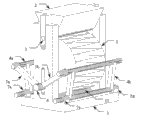
Fig. 1 is the piece fixture schematic perspective view that a kind of split the law is measured Tensile Strength of Rock.
Fig. 2 is piece fixture erecting frame and the bearing block structure synoptic diagram that a kind of split the law is measured Tensile Strength of Rock.
Fig. 3 is the mechanical transmission mechanism synoptic diagram that a kind of split the law is measured the piece fixture of Tensile Strength of Rock.
Fig. 4 is the cushion block structural representation that a kind of split the law is measured the piece fixture of Tensile Strength of Rock.
Fig. 5 is rock sample and the filler strip way of contact synoptic diagram that a kind of split the law is measured the piece fixture of Tensile Strength of Rock.
Among the figure: erecting frame 1; Cushion block 2; Last filler strip 3; First, second centralizing bracket 4a, 4b; First, second connecting rod 5a, 5b; Pin 6; First, second, third, fourth bearing seat 7a, 7b, 7c, 7d; Rock sample 8; Following filler strip groove 9; First, second cushion block gathering sill 10a, 10b; Pin gathering sill 11; Last filler strip groove 12; Following filler strip 13.
Embodiment
Below in conjunction with accompanying drawing, the present invention is described in further detail:
According to Fig. 1, Fig. 2, Fig. 3, Fig. 4 as can be known, piece fixture structure of the present invention is the left-right symmetric shape, the piece fixture that a kind of split the law is measured Tensile Strength of Rock comprises erecting frame 1, cushion block 2, goes up filler strip 3, down filler strip 13, first, second centralizing bracket 4a, 4b, first, second connecting rod 5a, 5b, pin 6, first, second, third, fourth bearing seat 7a, 7b, 7c, 7d, rock sample 8, down filler strip groove 9, first, second cushion block gathering sill 10a, 10b, pin gathering sill 11, go up filler strip groove 12, filler strip 13 down.Its annexation is: the piece fixture structure is the left-right symmetric shape, the first centralizing bracket 4a is by first, the second bearing seat 7a, 7b links to each other with erecting frame 1, the second centralizing bracket 4b is by the 3rd, the 4th bearing seat 7c, 7d links to each other with erecting frame 1, first connecting rod 5a one end links to each other with the first centralizing bracket 4a, the first connecting rod 5a other end links to each other with pin 6, second connecting rod 5b one end links to each other with the second centralizing bracket 4b, the second connecting rod 5b other end links to each other with pin 6, pin 6 is with first, second connecting rod 5a, the end of 5b is stuck in gathering sill 11 1 sides of pin 6, cushion block 2 is stuck in first, the second cushion block gathering sill 10a, in the 10b, last filler strip 3 is assemblied in corresponding going up in the filler strip groove 12.Erecting frame 1 front and back top side wall has first, second cushion block gathering sill 10a, 10b, and its effect is spacer pad 2 and the trend that retrains cushion block 2 in the process of the test.Erecting frame 1 front side wall bottom has pin gathering sill 11, and its width is slightly larger than pin 6 diameters, and its effect is that guide pin 6 only can be along vertical slip.Erecting frame 1 bottom centre's line position has down filler strip groove 9, and its effect is to lay down filler strip 13.First, second, third, fourth bearing seat 7a, 7b, 7c, 7d are assembled to respectively on four angles of erecting frame 1 bottom, its parallel axes is in following filler strip groove 9 and be the left-right symmetric shape, the first centralizing bracket 4a can first, second bearing seat 7a, 7b axis be that axle freely rotates, the axis that the second centralizing bracket 4b can the 3rd, the 4th bearing seat 7c, 7d is spool freely to rotate.First connecting rod 5a one end links to each other with the first centralizing bracket 4a, second connecting rod 5b one end links to each other with the second centralizing bracket 4b, pin 6 is stuck in pin gathering sill 11 1 sides with the end of first, second connecting rod 5a, 5b, when pin 6 when pin gathering sill 11 slides, the bootable first centralizing bracket 4a and the second centralizing bracket 4b rotate synchronously.Have filler strip groove 12 near the center line of cushion block 2 bottoms, its effect is to lay filler strip 3, can smear an amount of butter or colloid in last filler strip groove 12 in the process of the test, will go up filler strip 3 and be bonded in the filler strip groove 12, drops in the operating process preventing.There is projection both sides, cushion block 2 front and back, and its width is slightly larger than the width of first, second cushion block locating slot 10a, 10b, its objective is that guiding cushion block 2 only can be along vertical motion.
Among Fig. 5, rock sample 8 is objective for implementation of the present invention, is right cylinder.Dotted line is represented the diameter line of rock sample 8 among Fig. 5, last filler strip 3 and down filler strip 13 be fixed among the figure on the diameter line corresponding bus lines through the constraint of devices, thereby the stress that has realized rock sample 8 in the process of the test is in strict conformity with theory of mechanics and related specifications requirement.
The type testing step of using the present invention to carry out the Tensile Strength of Rock test is:
1) placing apparatus of the present invention on the pressure testing machine between the push-down head;
2) right cylinder rock sample 8 is put into piece fixture, and the axial direction of right cylinder rock sample 8 and filler strip direction are consistent as far as possible;
3) hand pulls down untie-sell nail 6, driving the first centralizing bracket 4a, the second centralizing bracket 4b rotates to the inside synchronously, guiding rock sample 8 accurate centerings, the another hand will be stained with the cushion block 2 of filler strip 3 and put into cushion block gathering sill 10, filler strip 3 is contacted with rock sample 8, unclamp both hands, this moment, the first centralizing bracket 4a, the second centralizing bracket 4b can break away from rock sample 8 under himself action of gravity, and rock sample 8 can keep stable under the effect of cushion block 2 gravity;
4) the starting pressure testing machine is tested, and reaches the diameter line direction splitting of filler strip 13 correspondences down until rock sample 8 along last filler strip 3;
5) remove the rock sample 8 of cleavage fracture, copy step 2,3 to put into new rock sample 8 and carry out test for tensile strength, until the test job of finishing all test specimens.
Claims (2)
1. a split the law is measured the piece fixture of Tensile Strength of Rock, comprise erecting frame (1), cushion block (2), last filler strip (3), first centralizing bracket (4a), second centralizing bracket (4b), first connecting rod (5a), second connecting rod (5b), pin (6), clutch shaft bearing seat (7a), second bearing seat (7b), the 3rd bearing seat (7c), the 4th bearing seat (7d), following filler strip groove (9), the first cushion block gathering sill (10a), the second cushion block gathering sill (10b), pin gathering sill (11), last filler strip groove (12), following filler strip (13), it is characterized in that: the piece fixture structure is the left-right symmetric shape, first centralizing bracket (4a) is by clutch shaft bearing seat (7a), second bearing seat (7b) links to each other with erecting frame (1), second centralizing bracket (4b) is by the 3rd bearing seat (7c), the 4th bearing seat (7d) links to each other with erecting frame (1), first connecting rod (5a) end links to each other with first centralizing bracket (4a), first connecting rod (5a) other end links to each other with pin (6), second connecting rod (5b) end links to each other with second centralizing bracket (4b), second connecting rod (5b) other end links to each other with pin (6), pin (6) is with first connecting rod (5a), the end of second connecting rod (5b) is stuck in pin gathering sill (11) one sides, cushion block (2) is stuck in the first cushion block gathering sill (10a), in the second cushion block gathering sill (10b), last filler strip (3) is assemblied in the filler strip groove (12);
Top side wall has the first cushion block gathering sill (10a), the second cushion block gathering sill (10b) before and after the described erecting frame (1);
Described erecting frame (1) front side wall bottom has pin gathering sill (11), and erecting frame (1) bottom has down filler strip groove (9), and its effect is to lay down filler strip (13);
Described clutch shaft bearing seat (7a), second bearing seat (7b), the 3rd bearing seat (7c), the 4th bearing seat (7d) are assembled to respectively on four angles of erecting frame (1) bottom, and its parallel axes is in following filler strip groove (9) and be the left-right symmetric shape;
Described cushion block (2) bottom has filler strip groove (12), and last filler strip (3) is bonded in the filler strip groove (12).
2. a kind of split the law according to claim 1 is measured the piece fixture of Tensile Strength of Rock, it is characterized in that:
There is projection both sides before and after the described cushion block (2).
Priority Applications (1)
| Application Number | Priority Date | Filing Date | Title |
|---|---|---|---|
| CN2010102705329A CN101936851B (en) | 2010-09-02 | 2010-09-02 | Specimen clamp for measuring tensile strength of rock by splitting method |
Applications Claiming Priority (1)
| Application Number | Priority Date | Filing Date | Title |
|---|---|---|---|
| CN2010102705329A CN101936851B (en) | 2010-09-02 | 2010-09-02 | Specimen clamp for measuring tensile strength of rock by splitting method |
Publications (2)
| Publication Number | Publication Date |
|---|---|
| CN101936851A CN101936851A (en) | 2011-01-05 |
| CN101936851B true CN101936851B (en) | 2011-07-13 |
Family
ID=43390297
Family Applications (1)
| Application Number | Title | Priority Date | Filing Date |
|---|---|---|---|
| CN2010102705329A Expired - Fee Related CN101936851B (en) | 2010-09-02 | 2010-09-02 | Specimen clamp for measuring tensile strength of rock by splitting method |
Country Status (1)
| Country | Link |
|---|---|
| CN (1) | CN101936851B (en) |
Families Citing this family (8)
| Publication number | Priority date | Publication date | Assignee | Title |
|---|---|---|---|---|
| CN102183410B (en) * | 2011-01-27 | 2014-05-14 | 中国科学院武汉岩土力学研究所 | Brazilian split method for measuring elastic parameter of rock under extension condition |
| CN103471923B (en) * | 2013-09-25 | 2015-04-08 | 中国地震局地壳应力研究所 | Rapid testing machine for multi-diameter rock core hydraulic fracturing tensile strength |
| CN104390844B (en) * | 2014-11-25 | 2016-08-24 | 三峡大学 | The test method of Tensile Strength of Rock under any sheet reason angle is surveyed by single rock sample |
| CN105352796B (en) * | 2015-10-26 | 2018-06-12 | 天津大学 | Brazilian cleavage stress-strain-gauge test the device of variable element combination and test method |
| CN106053209B (en) * | 2016-07-13 | 2018-09-11 | 长江水利委员会长江科学院 | Test in Situ tensile shear testing system and method |
| CN107389906A (en) * | 2017-09-01 | 2017-11-24 | 中国电建集团成都勘测设计研究院有限公司 | For testing the experimental provision system of distress in concrete self-healing ability |
| CN110044688B (en) * | 2019-04-23 | 2024-04-09 | 浙江工业大学 | Multifunctional clamp for concrete splitting tensile strength experiment |
| CN112665987B (en) * | 2020-12-18 | 2021-08-27 | 西南石油大学 | Device and method for testing tensile strength of rock core under confining pressure condition based on Brazilian splitting |
Citations (1)
| Publication number | Priority date | Publication date | Assignee | Title |
|---|---|---|---|---|
| CN1793829A (en) * | 2005-12-26 | 2006-06-28 | 长安大学 | Low temperature cracking test instrument of asphalt mixture |
Family Cites Families (1)
| Publication number | Priority date | Publication date | Assignee | Title |
|---|---|---|---|---|
| JP2002116123A (en) * | 2000-10-06 | 2002-04-19 | Nippon Steel Corp | Tension testing device of cylindrical material |
-
2010
- 2010-09-02 CN CN2010102705329A patent/CN101936851B/en not_active Expired - Fee Related
Patent Citations (1)
| Publication number | Priority date | Publication date | Assignee | Title |
|---|---|---|---|---|
| CN1793829A (en) * | 2005-12-26 | 2006-06-28 | 长安大学 | Low temperature cracking test instrument of asphalt mixture |
Also Published As
| Publication number | Publication date |
|---|---|
| CN101936851A (en) | 2011-01-05 |
Similar Documents
| Publication | Publication Date | Title |
|---|---|---|
| CN101936851B (en) | Specimen clamp for measuring tensile strength of rock by splitting method | |
| CN102928295B (en) | Small-sized certainly to the heart unidirectional loading biaxial tension test test unit | |
| CN103808562B (en) | For the test fixture of nonmetallic materials 500K ~ 4.2K mechanical stretch performance | |
| KR101649451B1 (en) | Universal testing machine with muti-axis | |
| CN104458446B (en) | Device and method for testing shearing characteristics of non-metallic materials | |
| CN102410963A (en) | Experiment device for testing fatigue life of threading connector of petroleum drill | |
| CN104677584A (en) | Simulative testing device and method of drilling tool thread dynamic fatigue | |
| CN206095777U (en) | Measuring accessories of creep, duration running fracture sample | |
| CN104897412A (en) | Loading device for axle housing bench test of passenger car | |
| CN108593461B (en) | Rubber performance test method | |
| CN104359764A (en) | Secondary stress loading test device convenient for reinforcing structure under constant load and manufacturing method of secondary stress loading test device | |
| CN103149092B (en) | Drawing device split by multifunctional concrete test specimen | |
| CN210269445U (en) | Multidimensional loading comprehensive test system | |
| CN210154940U (en) | Pipe ring rigidity detection equipment | |
| CN208254934U (en) | A kind of three-point bending vibrating fatigue device with axial tension function | |
| CN216718067U (en) | Anti-rotation self-centering bending test tool | |
| CN102928289A (en) | Tensile test clamping device for universal testing machine | |
| CN205374163U (en) | Realize direct tensile test bench of rock sample | |
| CN202485990U (en) | Carton box compression strength detection device | |
| CN109444040A (en) | A kind of experimental rig for testing FRP plate and steel interfacial bond property | |
| CN113670812A (en) | Loading device for researching bonding performance of FRP cloth and concrete interface | |
| CN110530706B (en) | Loading device and test method for double-material interface under normal stress constraint | |
| CN209513567U (en) | A kind of experimental rig for testing FRP plate and steel interfacial bond property | |
| CN104297075A (en) | A metal wire torsion test method for a steel wire rope | |
| CN102175522B (en) | Displacement transmitting device for clamping extensometer |
Legal Events
| Date | Code | Title | Description |
|---|---|---|---|
| C06 | Publication | ||
| PB01 | Publication | ||
| C10 | Entry into substantive examination | ||
| SE01 | Entry into force of request for substantive examination | ||
| C14 | Grant of patent or utility model | ||
| GR01 | Patent grant | ||
| CF01 | Termination of patent right due to non-payment of annual fee |
Granted publication date: 20110713 Termination date: 20170902 |
|
| CF01 | Termination of patent right due to non-payment of annual fee |