CN101902988A - The induction system of stent graft - Google Patents
The induction system of stent graft Download PDFInfo
- Publication number
- CN101902988A CN101902988A CN2009801015196A CN200980101519A CN101902988A CN 101902988 A CN101902988 A CN 101902988A CN 2009801015196 A CN2009801015196 A CN 2009801015196A CN 200980101519 A CN200980101519 A CN 200980101519A CN 101902988 A CN101902988 A CN 101902988A
- Authority
- CN
- China
- Prior art keywords
- interstitital texture
- shelf
- tether
- interstitital
- texture
- Prior art date
- Legal status (The legal status is an assumption and is not a legal conclusion. Google has not performed a legal analysis and makes no representation as to the accuracy of the status listed.)
- Pending
Links
Images


Classifications
-
- A—HUMAN NECESSITIES
- A61—MEDICAL OR VETERINARY SCIENCE; HYGIENE
- A61B—DIAGNOSIS; SURGERY; IDENTIFICATION
- A61B17/00—Surgical instruments, devices or methods, e.g. tourniquets
- A61B17/12—Surgical instruments, devices or methods, e.g. tourniquets for ligaturing or otherwise compressing tubular parts of the body, e.g. blood vessels, umbilical cord
- A61B17/12022—Occluding by internal devices, e.g. balloons or releasable wires
- A61B17/12099—Occluding by internal devices, e.g. balloons or releasable wires characterised by the location of the occluder
- A61B17/12109—Occluding by internal devices, e.g. balloons or releasable wires characterised by the location of the occluder in a blood vessel
- A61B17/12113—Occluding by internal devices, e.g. balloons or releasable wires characterised by the location of the occluder in a blood vessel within an aneurysm
- A61B17/12118—Occluding by internal devices, e.g. balloons or releasable wires characterised by the location of the occluder in a blood vessel within an aneurysm for positioning in conjunction with a stent
-
- A—HUMAN NECESSITIES
- A61—MEDICAL OR VETERINARY SCIENCE; HYGIENE
- A61B—DIAGNOSIS; SURGERY; IDENTIFICATION
- A61B17/00—Surgical instruments, devices or methods, e.g. tourniquets
- A61B17/12—Surgical instruments, devices or methods, e.g. tourniquets for ligaturing or otherwise compressing tubular parts of the body, e.g. blood vessels, umbilical cord
- A61B17/12022—Occluding by internal devices, e.g. balloons or releasable wires
- A61B17/12131—Occluding by internal devices, e.g. balloons or releasable wires characterised by the type of occluding device
- A61B17/12136—Balloons
-
- A—HUMAN NECESSITIES
- A61—MEDICAL OR VETERINARY SCIENCE; HYGIENE
- A61B—DIAGNOSIS; SURGERY; IDENTIFICATION
- A61B17/00—Surgical instruments, devices or methods, e.g. tourniquets
- A61B17/12—Surgical instruments, devices or methods, e.g. tourniquets for ligaturing or otherwise compressing tubular parts of the body, e.g. blood vessels, umbilical cord
- A61B17/12022—Occluding by internal devices, e.g. balloons or releasable wires
- A61B17/12131—Occluding by internal devices, e.g. balloons or releasable wires characterised by the type of occluding device
- A61B17/12181—Occluding by internal devices, e.g. balloons or releasable wires characterised by the type of occluding device formed by fluidized, gelatinous or cellular remodelable materials, e.g. embolic liquids, foams or extracellular matrices
- A61B17/12186—Occluding by internal devices, e.g. balloons or releasable wires characterised by the type of occluding device formed by fluidized, gelatinous or cellular remodelable materials, e.g. embolic liquids, foams or extracellular matrices liquid materials adapted to be injected
-
- A—HUMAN NECESSITIES
- A61—MEDICAL OR VETERINARY SCIENCE; HYGIENE
- A61B—DIAGNOSIS; SURGERY; IDENTIFICATION
- A61B17/00—Surgical instruments, devices or methods, e.g. tourniquets
- A61B17/12—Surgical instruments, devices or methods, e.g. tourniquets for ligaturing or otherwise compressing tubular parts of the body, e.g. blood vessels, umbilical cord
- A61B17/12022—Occluding by internal devices, e.g. balloons or releasable wires
- A61B17/12131—Occluding by internal devices, e.g. balloons or releasable wires characterised by the type of occluding device
- A61B17/12181—Occluding by internal devices, e.g. balloons or releasable wires characterised by the type of occluding device formed by fluidized, gelatinous or cellular remodelable materials, e.g. embolic liquids, foams or extracellular matrices
- A61B17/12195—Occluding by internal devices, e.g. balloons or releasable wires characterised by the type of occluding device formed by fluidized, gelatinous or cellular remodelable materials, e.g. embolic liquids, foams or extracellular matrices comprising a curable material
-
- A—HUMAN NECESSITIES
- A61—MEDICAL OR VETERINARY SCIENCE; HYGIENE
- A61F—FILTERS IMPLANTABLE INTO BLOOD VESSELS; PROSTHESES; DEVICES PROVIDING PATENCY TO, OR PREVENTING COLLAPSING OF, TUBULAR STRUCTURES OF THE BODY, e.g. STENTS; ORTHOPAEDIC, NURSING OR CONTRACEPTIVE DEVICES; FOMENTATION; TREATMENT OR PROTECTION OF EYES OR EARS; BANDAGES, DRESSINGS OR ABSORBENT PADS; FIRST-AID KITS
- A61F2/00—Filters implantable into blood vessels; Prostheses, i.e. artificial substitutes or replacements for parts of the body; Appliances for connecting them with the body; Devices providing patency to, or preventing collapsing of, tubular structures of the body, e.g. stents
- A61F2/02—Prostheses implantable into the body
- A61F2/04—Hollow or tubular parts of organs, e.g. bladders, tracheae, bronchi or bile ducts
- A61F2/06—Blood vessels
- A61F2/07—Stent-grafts
-
- A—HUMAN NECESSITIES
- A61—MEDICAL OR VETERINARY SCIENCE; HYGIENE
- A61F—FILTERS IMPLANTABLE INTO BLOOD VESSELS; PROSTHESES; DEVICES PROVIDING PATENCY TO, OR PREVENTING COLLAPSING OF, TUBULAR STRUCTURES OF THE BODY, e.g. STENTS; ORTHOPAEDIC, NURSING OR CONTRACEPTIVE DEVICES; FOMENTATION; TREATMENT OR PROTECTION OF EYES OR EARS; BANDAGES, DRESSINGS OR ABSORBENT PADS; FIRST-AID KITS
- A61F2/00—Filters implantable into blood vessels; Prostheses, i.e. artificial substitutes or replacements for parts of the body; Appliances for connecting them with the body; Devices providing patency to, or preventing collapsing of, tubular structures of the body, e.g. stents
- A61F2/82—Devices providing patency to, or preventing collapsing of, tubular structures of the body, e.g. stents
- A61F2/86—Stents in a form characterised by the wire-like elements; Stents in the form characterised by a net-like or mesh-like structure
- A61F2/90—Stents in a form characterised by the wire-like elements; Stents in the form characterised by a net-like or mesh-like structure characterised by a net-like or mesh-like structure
-
- A—HUMAN NECESSITIES
- A61—MEDICAL OR VETERINARY SCIENCE; HYGIENE
- A61F—FILTERS IMPLANTABLE INTO BLOOD VESSELS; PROSTHESES; DEVICES PROVIDING PATENCY TO, OR PREVENTING COLLAPSING OF, TUBULAR STRUCTURES OF THE BODY, e.g. STENTS; ORTHOPAEDIC, NURSING OR CONTRACEPTIVE DEVICES; FOMENTATION; TREATMENT OR PROTECTION OF EYES OR EARS; BANDAGES, DRESSINGS OR ABSORBENT PADS; FIRST-AID KITS
- A61F2/00—Filters implantable into blood vessels; Prostheses, i.e. artificial substitutes or replacements for parts of the body; Appliances for connecting them with the body; Devices providing patency to, or preventing collapsing of, tubular structures of the body, e.g. stents
- A61F2/95—Instruments specially adapted for placement or removal of stents or stent-grafts
- A61F2/954—Instruments specially adapted for placement or removal of stents or stent-grafts for placing stents or stent-grafts in a bifurcation
-
- A—HUMAN NECESSITIES
- A61—MEDICAL OR VETERINARY SCIENCE; HYGIENE
- A61M—DEVICES FOR INTRODUCING MEDIA INTO, OR ONTO, THE BODY; DEVICES FOR TRANSDUCING BODY MEDIA OR FOR TAKING MEDIA FROM THE BODY; DEVICES FOR PRODUCING OR ENDING SLEEP OR STUPOR
- A61M25/00—Catheters; Hollow probes
- A61M25/10—Balloon catheters
- A61M25/1018—Balloon inflating or inflation-control devices
- A61M25/10181—Means for forcing inflation fluid into the balloon
- A61M25/10182—Injector syringes
-
- A—HUMAN NECESSITIES
- A61—MEDICAL OR VETERINARY SCIENCE; HYGIENE
- A61M—DEVICES FOR INTRODUCING MEDIA INTO, OR ONTO, THE BODY; DEVICES FOR TRANSDUCING BODY MEDIA OR FOR TAKING MEDIA FROM THE BODY; DEVICES FOR PRODUCING OR ENDING SLEEP OR STUPOR
- A61M25/00—Catheters; Hollow probes
- A61M25/10—Balloon catheters
- A61M25/1018—Balloon inflating or inflation-control devices
- A61M25/10184—Means for controlling or monitoring inflation or deflation
- A61M25/10187—Indicators for the level of inflation or deflation
-
- A—HUMAN NECESSITIES
- A61—MEDICAL OR VETERINARY SCIENCE; HYGIENE
- A61F—FILTERS IMPLANTABLE INTO BLOOD VESSELS; PROSTHESES; DEVICES PROVIDING PATENCY TO, OR PREVENTING COLLAPSING OF, TUBULAR STRUCTURES OF THE BODY, e.g. STENTS; ORTHOPAEDIC, NURSING OR CONTRACEPTIVE DEVICES; FOMENTATION; TREATMENT OR PROTECTION OF EYES OR EARS; BANDAGES, DRESSINGS OR ABSORBENT PADS; FIRST-AID KITS
- A61F2/00—Filters implantable into blood vessels; Prostheses, i.e. artificial substitutes or replacements for parts of the body; Appliances for connecting them with the body; Devices providing patency to, or preventing collapsing of, tubular structures of the body, e.g. stents
- A61F2/02—Prostheses implantable into the body
- A61F2/04—Hollow or tubular parts of organs, e.g. bladders, tracheae, bronchi or bile ducts
- A61F2/06—Blood vessels
- A61F2002/065—Y-shaped blood vessels
- A61F2002/067—Y-shaped blood vessels modular
-
- A—HUMAN NECESSITIES
- A61—MEDICAL OR VETERINARY SCIENCE; HYGIENE
- A61F—FILTERS IMPLANTABLE INTO BLOOD VESSELS; PROSTHESES; DEVICES PROVIDING PATENCY TO, OR PREVENTING COLLAPSING OF, TUBULAR STRUCTURES OF THE BODY, e.g. STENTS; ORTHOPAEDIC, NURSING OR CONTRACEPTIVE DEVICES; FOMENTATION; TREATMENT OR PROTECTION OF EYES OR EARS; BANDAGES, DRESSINGS OR ABSORBENT PADS; FIRST-AID KITS
- A61F2/00—Filters implantable into blood vessels; Prostheses, i.e. artificial substitutes or replacements for parts of the body; Appliances for connecting them with the body; Devices providing patency to, or preventing collapsing of, tubular structures of the body, e.g. stents
- A61F2/02—Prostheses implantable into the body
- A61F2/04—Hollow or tubular parts of organs, e.g. bladders, tracheae, bronchi or bile ducts
- A61F2/06—Blood vessels
- A61F2/07—Stent-grafts
- A61F2002/077—Stent-grafts having means to fill the space between stent-graft and aneurysm wall, e.g. a sleeve
-
- A—HUMAN NECESSITIES
- A61—MEDICAL OR VETERINARY SCIENCE; HYGIENE
- A61F—FILTERS IMPLANTABLE INTO BLOOD VESSELS; PROSTHESES; DEVICES PROVIDING PATENCY TO, OR PREVENTING COLLAPSING OF, TUBULAR STRUCTURES OF THE BODY, e.g. STENTS; ORTHOPAEDIC, NURSING OR CONTRACEPTIVE DEVICES; FOMENTATION; TREATMENT OR PROTECTION OF EYES OR EARS; BANDAGES, DRESSINGS OR ABSORBENT PADS; FIRST-AID KITS
- A61F2/00—Filters implantable into blood vessels; Prostheses, i.e. artificial substitutes or replacements for parts of the body; Appliances for connecting them with the body; Devices providing patency to, or preventing collapsing of, tubular structures of the body, e.g. stents
- A61F2/02—Prostheses implantable into the body
- A61F2/30—Joints
- A61F2002/30001—Additional features of subject-matter classified in A61F2/28, A61F2/30 and subgroups thereof
- A61F2002/30316—The prosthesis having different structural features at different locations within the same prosthesis; Connections between prosthetic parts; Special structural features of bone or joint prostheses not otherwise provided for
- A61F2002/30535—Special structural features of bone or joint prostheses not otherwise provided for
- A61F2002/30581—Special structural features of bone or joint prostheses not otherwise provided for having a pocket filled with fluid, e.g. liquid
- A61F2002/30583—Special structural features of bone or joint prostheses not otherwise provided for having a pocket filled with fluid, e.g. liquid filled with hardenable fluid, e.g. curable in-situ
-
- A—HUMAN NECESSITIES
- A61—MEDICAL OR VETERINARY SCIENCE; HYGIENE
- A61F—FILTERS IMPLANTABLE INTO BLOOD VESSELS; PROSTHESES; DEVICES PROVIDING PATENCY TO, OR PREVENTING COLLAPSING OF, TUBULAR STRUCTURES OF THE BODY, e.g. STENTS; ORTHOPAEDIC, NURSING OR CONTRACEPTIVE DEVICES; FOMENTATION; TREATMENT OR PROTECTION OF EYES OR EARS; BANDAGES, DRESSINGS OR ABSORBENT PADS; FIRST-AID KITS
- A61F2/00—Filters implantable into blood vessels; Prostheses, i.e. artificial substitutes or replacements for parts of the body; Appliances for connecting them with the body; Devices providing patency to, or preventing collapsing of, tubular structures of the body, e.g. stents
- A61F2/02—Prostheses implantable into the body
- A61F2/30—Joints
- A61F2002/30001—Additional features of subject-matter classified in A61F2/28, A61F2/30 and subgroups thereof
- A61F2002/30316—The prosthesis having different structural features at different locations within the same prosthesis; Connections between prosthetic parts; Special structural features of bone or joint prostheses not otherwise provided for
- A61F2002/30535—Special structural features of bone or joint prostheses not otherwise provided for
- A61F2002/30604—Special structural features of bone or joint prostheses not otherwise provided for modular
-
- A—HUMAN NECESSITIES
- A61—MEDICAL OR VETERINARY SCIENCE; HYGIENE
- A61F—FILTERS IMPLANTABLE INTO BLOOD VESSELS; PROSTHESES; DEVICES PROVIDING PATENCY TO, OR PREVENTING COLLAPSING OF, TUBULAR STRUCTURES OF THE BODY, e.g. STENTS; ORTHOPAEDIC, NURSING OR CONTRACEPTIVE DEVICES; FOMENTATION; TREATMENT OR PROTECTION OF EYES OR EARS; BANDAGES, DRESSINGS OR ABSORBENT PADS; FIRST-AID KITS
- A61F2/00—Filters implantable into blood vessels; Prostheses, i.e. artificial substitutes or replacements for parts of the body; Appliances for connecting them with the body; Devices providing patency to, or preventing collapsing of, tubular structures of the body, e.g. stents
- A61F2/95—Instruments specially adapted for placement or removal of stents or stent-grafts
- A61F2002/9505—Instruments specially adapted for placement or removal of stents or stent-grafts having retaining means other than an outer sleeve, e.g. male-female connector between stent and instrument
- A61F2002/9511—Instruments specially adapted for placement or removal of stents or stent-grafts having retaining means other than an outer sleeve, e.g. male-female connector between stent and instrument the retaining means being filaments or wires
-
- A—HUMAN NECESSITIES
- A61—MEDICAL OR VETERINARY SCIENCE; HYGIENE
- A61F—FILTERS IMPLANTABLE INTO BLOOD VESSELS; PROSTHESES; DEVICES PROVIDING PATENCY TO, OR PREVENTING COLLAPSING OF, TUBULAR STRUCTURES OF THE BODY, e.g. STENTS; ORTHOPAEDIC, NURSING OR CONTRACEPTIVE DEVICES; FOMENTATION; TREATMENT OR PROTECTION OF EYES OR EARS; BANDAGES, DRESSINGS OR ABSORBENT PADS; FIRST-AID KITS
- A61F2210/00—Particular material properties of prostheses classified in groups A61F2/00 - A61F2/26 or A61F2/82 or A61F9/00 or A61F11/00 or subgroups thereof
- A61F2210/0085—Particular material properties of prostheses classified in groups A61F2/00 - A61F2/26 or A61F2/82 or A61F9/00 or A61F11/00 or subgroups thereof hardenable in situ, e.g. epoxy resins
-
- A—HUMAN NECESSITIES
- A61—MEDICAL OR VETERINARY SCIENCE; HYGIENE
- A61F—FILTERS IMPLANTABLE INTO BLOOD VESSELS; PROSTHESES; DEVICES PROVIDING PATENCY TO, OR PREVENTING COLLAPSING OF, TUBULAR STRUCTURES OF THE BODY, e.g. STENTS; ORTHOPAEDIC, NURSING OR CONTRACEPTIVE DEVICES; FOMENTATION; TREATMENT OR PROTECTION OF EYES OR EARS; BANDAGES, DRESSINGS OR ABSORBENT PADS; FIRST-AID KITS
- A61F2230/00—Geometry of prostheses classified in groups A61F2/00 - A61F2/26 or A61F2/82 or A61F9/00 or A61F11/00 or subgroups thereof
- A61F2230/0002—Two-dimensional shapes, e.g. cross-sections
- A61F2230/0028—Shapes in the form of latin or greek characters
- A61F2230/0034—D-shaped
-
- A—HUMAN NECESSITIES
- A61—MEDICAL OR VETERINARY SCIENCE; HYGIENE
- A61F—FILTERS IMPLANTABLE INTO BLOOD VESSELS; PROSTHESES; DEVICES PROVIDING PATENCY TO, OR PREVENTING COLLAPSING OF, TUBULAR STRUCTURES OF THE BODY, e.g. STENTS; ORTHOPAEDIC, NURSING OR CONTRACEPTIVE DEVICES; FOMENTATION; TREATMENT OR PROTECTION OF EYES OR EARS; BANDAGES, DRESSINGS OR ABSORBENT PADS; FIRST-AID KITS
- A61F2250/00—Special features of prostheses classified in groups A61F2/00 - A61F2/26 or A61F2/82 or A61F9/00 or A61F11/00 or subgroups thereof
- A61F2250/0003—Special features of prostheses classified in groups A61F2/00 - A61F2/26 or A61F2/82 or A61F9/00 or A61F11/00 or subgroups thereof having an inflatable pocket filled with fluid, e.g. liquid or gas
-
- A—HUMAN NECESSITIES
- A61—MEDICAL OR VETERINARY SCIENCE; HYGIENE
- A61F—FILTERS IMPLANTABLE INTO BLOOD VESSELS; PROSTHESES; DEVICES PROVIDING PATENCY TO, OR PREVENTING COLLAPSING OF, TUBULAR STRUCTURES OF THE BODY, e.g. STENTS; ORTHOPAEDIC, NURSING OR CONTRACEPTIVE DEVICES; FOMENTATION; TREATMENT OR PROTECTION OF EYES OR EARS; BANDAGES, DRESSINGS OR ABSORBENT PADS; FIRST-AID KITS
- A61F2250/00—Special features of prostheses classified in groups A61F2/00 - A61F2/26 or A61F2/82 or A61F9/00 or A61F11/00 or subgroups thereof
- A61F2250/0058—Additional features; Implant or prostheses properties not otherwise provided for
- A61F2250/006—Additional features; Implant or prostheses properties not otherwise provided for modular
-
- A—HUMAN NECESSITIES
- A61—MEDICAL OR VETERINARY SCIENCE; HYGIENE
- A61M—DEVICES FOR INTRODUCING MEDIA INTO, OR ONTO, THE BODY; DEVICES FOR TRANSDUCING BODY MEDIA OR FOR TAKING MEDIA FROM THE BODY; DEVICES FOR PRODUCING OR ENDING SLEEP OR STUPOR
- A61M25/00—Catheters; Hollow probes
- A61M25/0067—Catheters; Hollow probes characterised by the distal end, e.g. tips
- A61M25/0068—Static characteristics of the catheter tip, e.g. shape, atraumatic tip, curved tip or tip structure
- A61M25/007—Side holes, e.g. their profiles or arrangements; Provisions to keep side holes unblocked
-
- A—HUMAN NECESSITIES
- A61—MEDICAL OR VETERINARY SCIENCE; HYGIENE
- A61M—DEVICES FOR INTRODUCING MEDIA INTO, OR ONTO, THE BODY; DEVICES FOR TRANSDUCING BODY MEDIA OR FOR TAKING MEDIA FROM THE BODY; DEVICES FOR PRODUCING OR ENDING SLEEP OR STUPOR
- A61M25/00—Catheters; Hollow probes
- A61M25/10—Balloon catheters
- A61M25/1018—Balloon inflating or inflation-control devices
- A61M25/10184—Means for controlling or monitoring inflation or deflation
- A61M25/10187—Indicators for the level of inflation or deflation
- A61M25/10188—Inflation or deflation data displays
Abstract
The aneurysmal system of a kind of treatment comprises: elongated flexible shaft and expandable members.Expandable scaffold is arranged on the expandable members and can expand into expansible structure from the flat structure of collapsing.The setting of double-walled interstitital texture and has outer wall and inwall on the top of the shelf.Interstitital texture is suitable for filling with hardenable fluid filled medium, so that outer wall accords with aneurysmal inner surface, and inwall forms the inner chamber of general tube shape so that channel of blood flow to be provided.In expansion structure, shelf cooperates the inwall of described interstitital texture.Tether links to each other with flexible shaft with interstitital texture releasedly, retrains the axially-movable relative to each other of all structures thus.
Description
Technical field
The present invention relates generally to medical system and Therapeutic Method.Specifically, the present invention relates to treat aneurysmal system and method.
Background technology
Aneurysm is often to be easy to disruptive enlarged or " heaving part " in the blood vessel, therefore there is serious risk in patient.Aneurysm can occur in any blood vessel, but in aneurysm occurs in cerebral vessels or patient's large artery trunks the time, then causes concern especially.
The present invention be more particularly directed to occur in the aneurysm in the large artery trunks, be referred to as aortic aneurysm especially.According to the position of aneurysm in large artery trunks with and shape and complexity, the aneurysm of the abdominal aorta of classifying (AAA).The aneurysm that kidney tremulous pulse below is found is referred to as the aneurysm of the abdominal aorta under the kidney.The aneurysm of the abdominal aorta on the kidney occurs in arteriorenal top, and the aortic aneurysm of chest (TAA) occurs in the aortic rising in top, laterally or in the sloping portion.
Aneurysm under the kidney is the most common, accounts for about 80 (80%) percent in the aneurysm of all large arteries.Aneurysm on the kidney is comparatively rare, accounts for about 20% in the aneurysm of all large arteries.The aortic aneurysm of chest the most rare and be difficult to most usually the treatment.
The aneurysm of most common form is " fusoid tumor ", wherein, heaves part and extends around whole aortic girths.Uncommon aneurysmal feature is that heaving part may be to be attached on the side of narrow neck place blood vessel.The aortic aneurysm of chest usually is that main artery wall (usually in the intermediate layer) internal hemorrhage is separated the separated aneurysm that causes.For these types and the aneurysmal prevailing Therapeutic Method of form is the surgical repair of opening.The patient of and obviously do not accompany disease healthier for others, the surgical repair of opening is success considerably.Yet the surgical operation of so opening also exists problem, because the large artery trunks of inaccessible abdominal part and chest, because the necessary clamped disconnection of large artery trunks, thereby heart of patient is brought very big damage.
In the past ten years, for not bearing the operating patient who opens, aneurysmal treatment has obtained application widely to the inner chamber graft to large artery trunks.In general, the inner chamber reparation by the either side in the groin or both sides iliac artery with " inner chamber mode " near aneurysm.Fabric or film tube that graft is normally supported and adheres to by various supporting structures are implanted such implant then, need assemble some parts or module on the spot usually.The post-operative recovery time of the interior surgical cavity of success is wanted much shorter more than the surgical operation of opening.
Yet many limitations are suffered in the reparation of present aortic aneurysm inner chamber.For example, most inner chamber repair patient can experience within first prosthesis 2 years in the near-end junction junction point of close heart () hemorrhage.However hemorrhage often can be stopped by surgical cavity in further, but the treatment that needs to do so subsequently increase cost significantly, is undesirable certainly for patient.Comparatively rare but even more serious problem is the migration of implant.Require the situation of position migration or slip the surgical repair that needs work to open from it in implant.This is a special problem, often is considered to not be accept operating good candidate target because accept the patient of inner chamber implant.
Other shortcoming of inner chamber implant system also relates to the expansion and the structure of implant at present.For example, the inner chamber system of many markets sales is for seem via skin is introduced excessive (more than the 12F).In addition, present apparatus often has hard and ring-shaped bearing framework that be difficult to carry, and is not suitable for treating the aneurysm of many complex geometry, especially, aneurysm under the kidney, its space between renal artery and aneurysm upper end is very little, and this aneurysm is referred to as short neck or does not have carotid aneurysm.Aneurysm with cranky geometry also is difficult to treatment.
Various reasons for this reason, hope can provide treatment large artery trunks inner chamber and minimally invasive aneurysmal improved method and system.Especially, hope can provide and carry the simple system of profile and can and can track in tortuous blood vessel and unfolded method via the skin conveying.It would also be desirable to provide the internal hemorrhage minimum or do not have hemorrhage prosthesis, it can stop migration, and be flexibility and can relatively easily launch, it can treat many rather than all aneurysmal structures, comprises short neck or does not have carotid aneurysm and have the highly irregularly shaped and aneurysm asymmetry geometry.Be desirable to provide the system and method compatible mutually in addition with inner chamber support and implant design at present, the support that comprises single inner chamber support and implant, bifurcated and implant, parallel support and implant, and with the compatibility of double-walled interstitital texture, this double-walled construction is owning together of the following stated and the theme of pending application.It would also be desirable to provide to provide feedback so that inner chamber repaired apparatus location and be deployed in system and method in the aneurysm to the operator.Described system and method preferably can just launch this support and implant in putting at first in support and implant.In addition, it would also be desirable to provide and be used for repairing the large artery trunks support of previous implantation and the system and method for implant, the implantation mode is also can implanting via skin of intracavity both.The present invention described below will satisfy these purposes of some at least.
United States Patent (USP) publication No.2006/0025853 discloses a kind of large artery trunks and other aneurysmal double-walled interstitital texture of being used for the treatment of.Unsettled and United States Patent (USP) publication No.2006/0212112 that own together has described and has used liner and stretcher to fix and seal the interior so double-walled interstitital texture of large artery trunks.This paper is to introduce the full content of these two pieces of patent publications referring to mode.PCT publication No.WO 01/21108 has described and has been attached to the expandable implant that is used for filling the aneurysmal center of large artery trunks graft.Be also shown in U.S. Patent No. 5,330,528; 5,534,024; 5,843,160; 6,168,592; 6,190,402; 6,312,462; 6,312,463; United States Patent (USP) publication No.2002/0045848; 2003/0014075; 2004/0204755; 2005/0004660; And PCT publication No.WO 02/102282.
Summary of the invention
The invention provides the aneurysmal system and method for treatment, especially, comprise the aortic aneurysm of abdominal aorta aneurysm (AAA) and chest large artery trunks aneurysm (TAA).This system can cut via skin or by surgical operation and be incorporated in the patient body, and this system also can have scope preferably at the overall diameter of 10French to 18French, and this overall diameter is preferably between the 12French to 16French.
In a first aspect of the present invention, a kind of system for the treatment of endovascular aneurysm comprises elongated flexible shaft, and this axle has proximal end region and remote area.The first double-walled interstitital texture is arranged on this remote area, and has outer wall and inwall.Interstitital texture can be filled with hardenable fluid filled medium, so that outer wall accords with aneurysmal inner surface, and inwall forms first inner chamber of general tube shape so that channel of blood flow to be provided.This system also comprises near first expandable scaffold that is arranged on the interstitital texture.This first shelf can radially expand at least a portion of the tubular inner chamber of interstitital texture, and interstitital texture is separated and separated with it vertically with first shelf.
In certain embodiments, first shelf can be at the near-end of interstitital texture, and in further embodiments, first shelf can be at the far-end of interstitital texture.Sometimes between an end of end of first shelf and interstitital texture, exist gap or spacing.First shelf is filled structure slidably and admits, so that first shelf and interstitital texture are concentrically with respect to one another, and interstitital texture is to providing covering around the shelf.
Sometimes, this induction system can comprise sheath, and this sheath is at least partially disposed on interstitital texture and/or the shelf.This sheath can have the terminal of taper and the slit of axial orientation can be arranged.This system also can comprise thrust tube, and this thrust tube is at least partially disposed on the flexible shaft and with the first double-walled interstitital texture and cooperates slidably.First tether can link to each other with interstitital texture, and this first tether can extend between the proximal end region of flexible shaft and remote area.This tether first double-walled interstitital texture that can be suitable for leading is axially moved along this axle with respect to first shelf.When interstitital texture axially moved with respect to first shelf, this tether also can be used to the pulling interstitital texture, cooperated slidably thus and located the interstitital texture and first shelf.Sometimes, induction system also can comprise second tether that links to each other with interstitital texture, and this second tether can extend between the proximal end region of flexible shaft and remote area.System can comprise one or more and link coupled eyelet of first interstitital texture or seam loop, and they can be suitable for admitting tether or pipe, and rises and do guide effect, or interstitital texture can comprise and the mutually link coupled socket of the wall of the interstitital texture of admitting pipe slidably.This system also can comprise the nose-cone that links to each other with the remote area of flexible shaft, and sometimes, tether can be coupled.Some part of tether may extend into outside the patient body.Tether links to each other with interstitital texture releasedly.
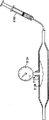
This system can comprise also that such as the such aerating device of syringe this aerating device links to each other with pressure monitor fluid ground with interstitital texture.Pressure monitor also can be connected with interstitital texture, when filling with hardenable fluid filled medium in interstitital texture, allows to monitor the pressure of interstitital texture.Pressure monitor can comprise Pressure gauge, character display etc.
Sometimes, interstitital texture comprises air relief valve, and alternative container can link to each other with its fluid ground.Air relief valve can be isolated with the first interstitital texture fluid ground, and container can be suitable for admitting with predetermined pressure from the effusive hardenable fluid filled medium of air relief valve.When using hardenable fluid filled at least in part, this container can be radiopaque.Other embodiment of system can have the visual detector that links to each other with interstitital texture fluid ground.This visual detector can have the primary importance and the second position, and wherein, when predetermined pressure was applied on the visual detector, this indicator moved to the second position from primary importance.This indicator under fluoroscope as seen.
Other embodiment can comprise that such as the such flat member that collapses of air bag this flat member that can collapse links to each other with Pressure gauge fluid ground.The flat member that can collapse can be positioned between interstitital texture outer wall and the aneurysm inner surface, and therefore, Pressure gauge indicates the pressure of interstitital texture when being filled.Other embodiment also can comprise such as the such flat member that collapses of air bag, this flat member that can collapse similarly can be positioned between aneurysm wall and the interstitital texture wall, its with link to each other such as the such compressing mechanism fluid ground of spring, this pressure texture has the primary importance and the second position.When interstitital texture was filled with, compressing mechanism provided predetermined power to resist the power that flat member acted on of can collapsing.When the power that flat member acted on when collapsing surpassed predetermined value, compressing mechanism just moved to the second position from primary importance.The flat member that can collapse can be an air bag.Some system also can comprise locking mechanism, and when interstitital texture was filled into predetermined pressure, this locking mechanism just can stop this interstitital texture of fluid filled.
In certain embodiments, interstitital texture can comprise is obedient to compartment, and when the outer wall of interstitital texture was consistent with aneurysmal inner surface, this was obedient to compartment and will be out of shape.Compartment can have generally flat part, and can be connected with pressure indicator fluid ground.
Sometimes, first shelf or second shelf can comprise zone and all the other zones that can crumple.When interstitital texture was pressurized to predetermined value, this zone that can crumple collapsed flat, and all the other zones keep fully expanding.In the embodiment that also has other, system can comprise also that such as the such expandable members of air bag this expandable members expand into expansible structure from the structure of shrinking, and it also links to each other with the axle of close remote area.Expandable members can be connected with pressure monitoring device fluid ground.Expandable members can have the zone of preformed, arcual or taper.
Shelf can be made up of metal, and can be expanded by air bag.Shelf or interstitital texture be the treatment reagent that discharges with controlled manner of portability also.Some treatment reagent comprises the antiprothrombin as the heparin, or promotes endotheliocyte and smooth muscle cell growth, sealing and attached reagent.Interstitital texture can comprise polymer.
System also can comprise the second double-walled interstitital texture with outer wall and inwall.This double-walled interstitital texture can be adjacent to first interstitital texture and be placed in the aneurysm, and but available stiffening fluid filled media is filled, so that outer wall accords with aneurysmal inner surface and accord with first interstitital texture, and second inner chamber that forms general tube shape is to provide channel of blood flow.System also can comprise and first shelf and isolating second shelf of interstitital texture, and described second shelf can expand at least a portion of the second tubular inner chamber of second interstitital texture.Second shelf can axially separate with second interstitital texture.Second shelf usually is the form identical with first interstitital texture with first shelf with second interstitital texture.Can be used as the packing material that is used for first and second interstitital textures by solidified flowable polymer in the original place.
System also can comprise releasable bindiny mechanism, and this bindiny mechanism links to each other with axle with first interstitital texture.Bindiny mechanism is suitable for reducing along the axially-movable with respect to shelf of the axle of interstitital texture.Releasable bindiny mechanism can comprise tether, and this tether links to each other with interstitital texture with axle releasedly.Interstitital texture also can comprise fills pipe, and this filling pipe links to each other with interstitital texture fluid ground and is suitable for filling described interstitital texture with filled media.This filling pipe also can comprise being slidingly arranged in fills the interior interior pipe of pipe.Interior pipe links to each other with filling Guan Keyu interstitital texture fluid ground.
In another aspect of this invention, a kind ofly treat the flexible shaft that aneurysmal method comprises provides elongated, this axle has proximal end region and remote area.Flexible shaft carries the first double-walled interstitital texture and first shelf being adjacent to far-end.In patient's vascular, advance elongated flexible shaft, can allow the first double-walled interstitital texture to cross aneurysm.Filling first interstitital texture with the fluid filled medium can make interstitital texture expand, make the outer wall of the interstitital texture of winning consistent with aneurysmal inner surface, and the inwall of first interstitital texture forms tubular basically first inner chamber, traverses aneurysmal first channel of blood flow to provide.Move first shelf vertically with respect to first interstitital texture, at least a portion of first shelf can be positioned at the tubular first interior intracavity basically, and first shelf that radially expands can make first shelf expand into expansion structure from contraction structure.
Move first shelf vertically and can comprise towards far-end first shelf is moved into first inner chamber, or move first shelf vertically and can be included on first shelf first interstitital texture of withdrawing towards near-end ground.Move first shelf vertically and also can comprise first shelf is withdrawn into intracavity first in towards near-end, or on first shelf towards mobile first interstitital texture distally.Sometimes, move first shelf vertically and can be included in guiding first interstitital texture on the tether, or with tether pulling first interstitital texture.This method also can comprise the sheath of withdrawing from first interstitital texture or first shelf, so that this part is not subjected to expansible constraint.This method also can comprise cooperating of thrust tube and first interstitital texture, to prevent its motion.This method also can comprise the filled media in sclerosis first interstitital texture.
This method also can comprise monitor pressures or by pressure that changes filled media or the filling that volume is controlled first or second interstitital texture.Filling to interstitital texture can comprise the actuating injection device, can be adjacent to the position monitor pressures of this injection device.This method also can be included in pressure and discharge pressure in the interstitital texture with air relief valve when surpassing predetermined value.Sometimes, air relief valve can completely cut off with the first interstitital texture fluid ground.Can fill the container that is connected with air relief valve fluid ground from the fluid that interstitital texture discharges, the operator can observe the inflated condition that this container is determined interstitital texture.Some pressure monitoring device can comprise the visual detector that links to each other with first interstitital texture.This indicator can have the primary importance and the second position, and when predetermined pressure was applied on the indicator, this indicator moved to the second position from primary importance.The operator can observe this indicator post to determine the occupied state of interstitital texture.
Other embodiment can comprise the flat member that can collapse like that such as air bag is positioned between interstitital texture outer wall and the aneurysm inwall.The operator observes the compressing mechanism with primary importance and second position that links to each other with interstitital texture.When interstitital texture was filled with, compressing mechanism provided predetermined power to resist the power that flat member acted on of can collapsing, and the power that flat member acted on when collapsing is when surpassing predetermined value, and compressing mechanism just moves to the second position from primary importance.Compressing mechanism can comprise spring, and the flat member that can collapse can comprise air bag.
The pressure that this method also can be included in supervision stops the step to the filling of interstitital texture when reaching predetermined value.Stop to fill and to lock filling device by mechanical means and make fluid not to be achieved from wherein carrying.Monitor pressures also can comprise observes first shelf.First shelf can have zone and all the other zones that can crumple, and when interstitital texture was pressurized to predetermined value, this zone that can crumple collapsed flat, and all the other zones keep fully expanding.
This method also can comprise provides the second elongated flexible axle with near-end and far-end.This second is carried the second double-walled interstitital texture and second shelf being adjacent to far-end.In patient's vascular, advance these second slender axles, can allow the second double-walled interstitital texture to cross aneurysm.Fill second interstitital texture with the fluid filled medium interstitital texture is expanded, make the outer wall of second interstitital texture form tubular basically second inner chamber, traverse aneurysmal second channel of blood flow to provide.Fill second interstitital texture and also can comprise pressure or the volume of controlling the fluid filled medium.Move second shelf vertically with respect to second interstitital texture, at least a portion of second shelf can be positioned at the tubular second interior intracavity basically, and second shelf that radially expands can make shelf expand into expansion structure from contraction structure.
Move second shelf vertically and can comprise towards far-end second shelf is moved into second inner chamber, or second interstitital texture of on second shelf, withdrawing towards near-end ground.Move second shelf vertically and also can comprise second shelf is withdrawn into intracavity second in towards near-end, or on second shelf towards mobile second interstitital texture distally.
This method also can comprise the sheath of withdrawing from second interstitital texture and/or second shelf, so that one of them or both are not subjected to expansible constraint.The withdrawal sheath also can comprise this sheath that splits.This method also can comprise the fluid filled medium in sclerosis second interstitital texture and monitor second pressure.This second pressure can be applied by the filled media in second interstitital texture.Frequently, can regulate flowing of filled media in response to second pressure that monitors.In certain embodiments, this method can comprise fills first or second interstitital texture, till interstitital texture is coupled to other interstitital texture, causes filled media to be discharged from first or second interstitital texture.In also having other embodiment, this method can comprise the airbag aeration on first or second slender axles, so that compress first and second interstitital textures, it abut against each other and against aneurysm.Frequently, when air bag was inflated, filled media was discharged from first or second interstitital texture.Any one shelf that radially expands can comprise being arranged near the inflation of the air bag the far-end.Air bag can comprise the zone of preformed, arcual or taper.
This method also can comprise release one releasable bindiny mechanism, and this bindiny mechanism connects interstitital texture and axle, so that interstitital texture is done axially-movable with respect to shelf, this bindiny mechanism also allows to discharge interstitital texture from axle.Discharge bindiny mechanism and can comprise the knot that discharges in the tether that connects interstitital texture and axle.Fill Guan Keyu interstitital texture fluid ground and connect, and the step of filling this interstitital texture can comprise and makes the fluid filled medium enter into interstitital texture by the filling pipe.The filling pipe can comprise being slidingly arranged in fills the interior pipe that also is communicated with interstitital texture fluid ground in the pipe.This method can comprise: remove interior pipe, and make additional fluid filled medium by filling pipe after interior pipe is removed.
In another aspect of this invention, a kind of system for the treatment of blood vessel medium-sized artery tumor comprises elongated flexible shaft, and this axle has proximal end region and remote area.Expandable members is arranged on and is adjacent to remote area, and expandable scaffold is arranged on the expandable members.First shelf can radially expand into expansion structure from the flat structure of collapsing.The first double-walled interstitital texture is arranged on first shelf.Interstitital texture has outer wall and inwall, and interstitital texture is suitable for filling with hardenable fluid filled medium, makes outer wall consistent with aneurysmal inner surface, and inwall forms tubular basically first inner chamber, so that channel of blood flow to be provided.In expansion structure, first shelf cooperates the inwall of interstitital texture.The first releasable bindiny mechanism connects interstitital texture and flexible shaft releasedly, and this bindiny mechanism can comprise tether, and tether links to each other with flexible shaft with interstitital texture releasedly.This bindiny mechanism's constraint interstitital texture is with respect to the motion of flexible shaft.
First tether can comprise stitching thread, and in certain embodiments, this system can comprise the locking silk that is arranged on the flexible shaft next door.The far-end of this locking silk links to each other with flexible shaft releasedly.Flexible shaft can comprise the nose-cone of wherein foraminous taper, and this nose-cone can link to each other with the remote area of flexible shaft, so that the far-end of locking silk links to each other with the nose cone body opening releasedly and is received within slidably in the nose cone body opening.First tether links to each other with this locking silk releasedly.Interstitital texture can comprise the attached regularly first tether circle thereon, and first tether can pass through this tether circle.The first tether circle can be arranged on the far-end of interstitital texture.In certain embodiments, first tether is releasably connected on the locking silk that has such as the such knot of pinned sheepshank.One end of first tether can be attached on the flexible shaft regularly.
This system also can comprise releasable second bindiny mechanism.This second mechanism can comprise tether, and tether links to each other with flexible shaft with interstitital texture releasedly.Second tether can be that this second tether can retrain the axially-movable of interstitital texture with respect to flexible shaft on interstitital texture and opposite end first tether.Second tether can comprise stitching thread, and is releasably connected to the locking silk.Second tether can be around locking filate lopping, and in certain embodiments, interstitital texture comprises and be arranged on the second tether circle on the opposite end with the first tether circle that this second tether can pass through the second tether circle attached with it regularly.Second tether can be connected on the flexible shaft, and is releasably connected on the flexible shaft that has such as the such knot of pinned sheepshank.
System also can comprise releasable second bindiny mechanism, and this second bindiny mechanism is such as tether, and this tether links to each other with flexible shaft with interstitital texture releasedly.Second tether can be arranged on interstitital texture and the same side first tether, and second tether can retrain the axially-movable of interstitital texture with respect to flexible shaft.Second tether can comprise stitching thread.In certain embodiments, this system also can comprise the second locking silk that is arranged on the flexible shaft next door.The far-end of the second locking silk links to each other with flexible shaft releasedly.The remote area of flexible shaft can include the nose-cone of the taper in second hole, and the far-end of the second locking silk is releasably connected to the second nose cone body opening and is received within wherein slidably.Second tether is releasably connected to the locking silk.
In certain embodiments, interstitital texture can comprise the attached regularly second tether circle thereon, and wherein, second tether is by the second tether circle.The second tether circle can be arranged on interstitital texture and the same side first tether circle.Second tether is releasably connected on the locking silk that has such as the such knot of pinned sheepshank.One end of second tether can be attached on the flexible shaft regularly.
System also can comprise the filling pipe that is connected with interstitital texture fluid ground.Filling pipe can be suitable for hardenable filled media is transported to interstitital texture.Fill pipe and can comprise a plurality of holes near its far-end, these holes are suitable for making hardenable filled media to flow through wherein and flow in the interstitital texture.Fill pipe and can comprise the interior outer filling pipe of managing and being slidably disposed on it of filling.Two Guan Douyu interstitital texture fluid ground link to each other.Probe can be arranged on fills in the pipe.Some embodiment can comprise and fill the short and small portion of filling that pipe fluid ground is connected and be connected with filling pipe fluid ground.Short and small of this filling can comprise scored areas, is separated into two parts to be suitable for allowing this fill short and small portion, and first keeps linking to each other with interstitital texture after filling with hardenable filled media, and second portion disconnects and be independent of first.
In the embodiment that also has other, system also can comprise the oversheath with inner chamber.In system being transported to the position process that will treat, interstitital texture, shelf and expandable members can be arranged in the sheath lumen.Other embodiment can comprise the second elongated flexible shaft, and this has proximal end region and remote area and is arranged on second expandable members that is adjacent to remote area.Second expandable scaffold can be arranged on second expandable members.Second shelf can radially expand into expansion structure from the flat structure of collapsing.This system also can comprise the second double-walled interstitital texture, and this second double-walled interstitital texture is arranged on second shelf.Second interstitital texture can have outer wall and inwall, and wherein, second interstitital texture is suitable for filling with hardenable fluid filled medium, makes outer wall consistent with aneurysmal inner surface, and inwall forms tubular basically first inner chamber, so that channel of blood flow to be provided.In expansion structure, second shelf cooperates the inwall of interstitital texture, and this system also can have the tether that is releasably connected to second interstitital texture and second flexible shaft.This tether can retrain the axially-movable of second interstitital texture with respect to second flexible shaft.
Also have on the other hand of the present invention, a kind of method of the patient body's of treatment internal aneurysm comprises provides an elongated flexible shaft, and this has the expandable members of near-end and far-end and close far-end.Flexible shaft carries and is positioned at radially expandable scaffold and be arranged on the first double-walled interstitital texture on first shelf of first on the expandable members.In patient's vascular, advance elongated flexible shaft, can allow first interstitital texture to be transported on the aneurysm.Make first shelf radially expand into expansion structure from contraction structure, wherein, in expansion structure, first shelf cooperates the inwall of first interstitital texture.Fill first interstitital texture with the first fluid filled media, make the outer wall of the interstitital texture of winning consistent, and the inwall of first interstitital texture forms tubular basically first inner chamber, traverses aneurysmal first channel of blood flow to provide with aneurysmal inner surface.Fill first interstitital texture with the first fluid filled media, also can estimate the volume of filling by removing and write down first filled media.Fill first interstitital texture with the second fluid filled medium, allow the outer wall of first interstitital texture to accord with aneurysmal inner surface, and the inwall of first interstitital texture forms tubular basically inner chamber, traverses aneurysmal first channel of blood flow to provide.The second fluid filled medium hardens in first interstitital texture, and then, first interstitital texture discharges from flexible shaft.Flexible shaft is recalled with away from first interstitital texture.
This method also can comprise with pre-fluid of filling fills in advance to first interstitital texture, consistent with aneurysmal inner surface up to the outer wall of first interstitital texture, thus, launches first interstitital texture.Pre-fill fluid can comprise saline, and can remove from first interstitital texture.This method also can comprise with pre-fill fluid fills in advance to first interstitital texture, consistent with aneurysmal inner surface up to the outer wall of first interstitital texture.Fill pressure and the volume that first interstitital texture can comprise that use is identical with measured value basically with the first fluid filled media and fill first interstitital texture with first filled media.Pre-fill fluid can comprise saline or contrast agent, to help observing filling process under the fluoroscope of X line.First filled media can be by the filling pipe that links to each other with the first interstitital texture fluid ground.
Radially expansible shelf can comprise to be inflated the air bag that is arranged on the flexible shaft.Sclerosis first fluid filled media can comprise the polymerization that makes the first fluid filled media on the spot in first interstitital texture.The first fluid filled media can comprise Polyethylene Glycol.
Such releasable bindiny mechanism can make first interstitital texture link to each other with flexible shaft such as tether, and the step that first interstitital texture discharges from flexible shaft can comprise discharge being connected of bindiny mechanism or disengagement and tether from first interstitital texture.One end of tether links to each other with the locking silk releasedly, breaks away from the tether step of connecting and can comprise withdrawal locking silk, and tether and locking silk are broken away from.Break away to be connected the tether circle that can comprise on first interstitital texture and discharge tether with tether.In certain embodiments, the second releasable bindiny mechanism such such as tether can make first interstitital texture link to each other with flexible shaft, and the step that discharges first interstitital texture from flexible shaft can comprise being connected of second tether and first interstitital texture.Discharging one or more bindiny mechanisms can make the filling pipe be separated with interstitital texture.
This method also can comprise recalls sheath to expand to allow first interstitital texture and first shelf away from first interstitital texture and first shelf.But monitor pressures in the first interstitital texture process of filling.The pressure that is monitored can be the pressure in the space between the pressure of the filled media in first interstitital texture or the first interstitital texture outer wall and the aneurysm wall.After hardenable filled media is transferred, can from first interstitital texture, discharges and fill pipe.Discharge the filling pipe and can comprise the short and small portion of filling that cut-out links to each other with first interstitital texture.
In certain embodiments, this method also can comprise provides the second elongated flexible shaft, and this has near-end and far-end and is arranged on second expandable members that is adjacent to far-end.The second flexible shaft portability is positioned at radially expandable second shelf on second expandable members, and the second double-walled interstitital texture can be arranged on second shelf.Second can be advanced in patient's vascular, so that second interstitital texture is transported to aneurysm, and second interstitital texture is filled with the second fluid filled medium, make that the outer wall of second interstitital texture is consistent with aneurysmal inner surface, and the inwall of second interstitital texture forms tubular basically second inner chamber, traverses aneurysmal second channel of blood flow to provide.Second shelf radially expand into expansion structure from contraction structure, and wherein, in expansion structure, second shelf cooperates the inwall of second interstitital texture.This second fluid filled medium can harden in second interstitital texture, and second flexible shaft can discharge from second interstitital texture.Can recall with away from second interstitital texture for second.
First interstitital texture can comprise the filling pipe that is connected with its fluid ground, and the step of filling first interstitital texture can comprise by filling pipe carries filled media.Fill pipe and can comprise that being slidingly arranged in filling manages interior pipe interior and that also be connected with interstitital texture fluid ground.This method also can comprise: remove interior pipe from fill pipe, and make filled media pass through to fill pipe after interior pipe has been removed, additional filled media is transported to interstitital texture.
In following description, will above-mentioned embodiment with other be described in further detail with reference to accompanying drawing.
Description of drawings
Fig. 1 illustrates the aneurysmal anatomy diagram of large artery trunks under the abdominal part kidney.
Fig. 2 illustrates a delivery conduit that carries single prosthesis systems, and this conduit comprises and is installed in the structural interstitital texture of shelf.
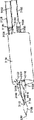
Fig. 3 illustrates and comprises the system that is transported to the aneurysmal a pair of prosthesis of large artery trunks under the abdominal part kidney, and wherein, each prosthesis comprises and carries the delivery conduit that is installed in the structural interstitital texture of shelf.
Fig. 4 A-4I illustrates and cures the use of the demonstration of system among the aneurysmal Fig. 3 of large artery trunks under the abdominal part kidney.
Fig. 5 illustrates the aneurysm that has with co-axial interstitital texture of delivery conduit and shelf and cures system.
Fig. 6 illustrates an aneurysm and cures system, and wherein, interstitital texture is separated with shelf.
Fig. 7 illustrate have with shelf axially the aneurysm of isolating interstitital texture cure system.
Fig. 8 illustrates the aneurysm that is similar to Fig. 7 and cures system, but the relative position of interstitital texture and shelf conversely.
Fig. 9 illustrate have with the expanded radially air bag axially the aneurysm of isolating interstitital texture cure system.
Figure 10 A-10B illustrates the use of various sheath embodiment.
Figure 11 A-11B illustrates the use of tether, and it helps the motion of guiding interstitital texture with respect to shelf.
Figure 12 A-12B illustrates the use of tether, and it helps the pulling interstitital texture to move towards shelf.
Figure 13 A-13D illustrates the use of pressure monitor, so that the filling of interstitital texture.
Figure 14 A-14C illustrates the use of pressure relief valve and overflow vessel.
Figure 15 A-15B illustrates the use of another pressure indicator mechanism.
Figure 16 A-16B illustrates the pressure monitor in the space between interstitital texture and aneurysm wall.
Figure 17 A-17C illustrates the balloon catheter with various pressure monitoring apparatuses.
Figure 18 A-18B illustrates the filling device that has locking mechanism.
Figure 19 A-19D illustrates various compartments in the interstitital texture.
Figure 20 A-20B illustrates the use as the plication region that is positioned at shelf of pressure indicator.
Figure 21 illustrates the aneurysm of the pressure monitor that has one and cures system.
Figure 22 A-22B illustrates the fixedly use of hooking of interstitital texture.
Figure 23 A-23B illustrates the pocket feature on the interstitital texture.
Figure 24 illustrates another alternate embodiment of interstitital texture and shelf induction system.
Figure 25 A-25B illustrates the use of pressure relief valve.
Figure 26 A-26C illustrates the use of cock.
Figure 27 A-27B illustrates how to control filling with the air bag on the delivery conduit.
Figure 28 A-28B illustrates how to control filling with interstitital texture itself.
Figure 29 illustrates the use of tether, and its help reduces the relative motion between interstitital texture and the inner frame as far as possible.
Figure 30 A-30B illustrates the use of pinned sheepshank.
Figure 31 illustrates the use of two tethers.
Figure 32 A-32B illustrates the location of interstitital texture with respect to inner frame.
Figure 33 illustrates the coupling of interstitital texture and inner frame.
Figure 34 illustrates a part of using spring arm to help open interstitital texture.
Figure 35 illustrates support column and locking use wiry.
Figure 36 A-36B illustrates the use of sheath.
Figure 37-38 illustrates other embodiment that utilizes sheath.
Figure 39 A-39C illustrates and fills separating of pipe and interstitital texture.
Figure 40 illustrates the embodiment that fills short-movie.
Figure 41 A-41B illustrates and fills separating of pipe and interstitital texture.
Figure 42 illustrates the fill port of filling in the pipe.
Figure 43 illustrates and fills separating of pipe and interstitital texture.
Figure 44 illustrates the obstruction of filling pipe.
Figure 45 A-45C illustrates interior and outer use of filling pipe.
Figure 46 A-46C illustrates the geometry of various filling pipes.
Figure 47 A-47B illustrates the induction system of demonstration.
Figure 48 A-48B illustrates the use of pressure monitor in the aneurysm treatment process.
Figure 49 illustrates the example embodiment of induction system.
Figure 50 A-50B illustrates the various embodiment that introduce contrast agent.
Figure 51 A-51B illustrates the pressure gauge that can cover the cover pressure screw.
Figure 52 A-52D illustrates the use of cracking sheath.
The specific embodiment
Fig. 1 illustrates the aneurysmal anatomy diagram of large artery trunks under the abdominal part kidney, and this anatomy figure comprises the chest large artery trunks (TA) of (IA) upper end place's renal artery (RA) that has iliac artery.Abdominal aorta aneurysm (AAA) is formed between renal artery (RA) and the iliac artery (IA) usually, and can have the zone that is positioned at the mural thrombus (T) on its inner surface (S) part.
Referring now to Fig. 2, being used for of one constructed in accordance with the principles is transported to aneurysmal system 10 with double-walled interstitital texture 12 (also being referred to as implant in the disclosure), this system 10 comprises the interstitital texture 12 on the inner frame 27 (also be referred to as shelf, support in the disclosure or prop up shelf) that is arranged on expanded radially, then, inner frame 27 and interstitital texture 12 all are installed in one and have on the delivery conduit 14 of expansion element 16 (being generally inflatable air bag) at its far-end.Expansion element 16 crosses the total length of inner frame 27, in case so that expansion element 16 expands, inner frame 27 can radially be expanded.Inner frame 27 crosses the total length of interstitital texture 12, cover and most of inner frame 27 is filled structure 12, yet inner frame 27 also has the zone of near-end and far-end, they not mulched ground extend beyond interstitital texture 12.Those skilled in the art will recognize that the length of interstitital texture, inner frame and inflatable element can be adjusted on demand, so relative length is not limited to the above length that discloses.The further details of relevant double-walled interstitital texture is disclosed in United States Patent (USP) publication No.2006/0212112 (attorney 025925-001610US), and the preferred embodiment of inner frame shelf is disclosed in U.S. Provisional Patent Application No.61/029,225 (attorney 025925-002710US) and U.S. Patent application No.12/371,087 (attorney 025925-002720US), this paper is to introduce the full content of this two patent referring to mode.Conduit 14 comprises guide wire inner chamber 18, airbag aeration inner chamber (not shown) or is used for other structure of other expansible elements that expands, and is used for filled media or material are transported to the filling pipe 20 of the inner space 22 of double-walled interstitital texture 12.This inner space 22 is formed between the outer wall 24 and inwall 26 of interstitital texture.In case fill with packing material or medium, then outer wall 24 will radially outwards expand, and shown in dotted line, inwall 26 will expand, and will be also shown in dotted line.The expansion of inwall 26 has formed an inner chamber 28.Expandable air bag or other structure 16 will expand and the inner frame 27 that expands accordingly, thereby the surface, inside of supporting and shaping inner chamber 28 is provided.In this embodiment, inflatable air bag is essentially cylinder form, and therefore, inner chamber is also with cylindrical.In other embodiments, air bag can preform so that be matched with the curvature of blood vessel more accurately.For example, when the aortic aneurysm of treatment, can use the preform or the arcual air bag of taper, make inner chamber mate large artery trunks basically.Can use various airbag structures, with the tortuous degree of coupling blood vessel.Any embodiment that the air bag of preform, arc or taper can be used for here being disclosed is so that obtain ideal shaping inner chamber.
Of the present invention special and preferred aspect, will use a pair of double-walled interstitital texture to treat large artery trunks aneurysm under the abdominal part kidney, rather than use single interstitital texture as shown in Figure 1 only.The system diagram that comprises a pair of interstitital texture like this is in Fig. 3, and this system comprises first interstitital texture 112 and second interstitital texture 212.Each interstitital texture 112 and 212 is installed in respectively on delivery conduit 114 and 214, but each system also has the inner frame shelf 127,227 of expanded radially.Interstitital texture 112 and 212, inner frame shelf 127,227 and delivery conduit 114 and 214 parts and front are identical substantially with reference to the single interstitital texture system 10 described parts of Fig. 1.Each interstitital texture 112 will give identical Reference numeral with 212 counterpart and be attached with radix 100 or radix 200. Interstitital texture 112 and 212 usually is positioned in the aneurysmal space to fill this space located adjacent one anotherly, just as following in particular with reference to Fig. 4 A-4I described.
Fig. 4 A-4I illustrates the use of the demonstration of the system that is used to cure the abdominal aorta aneurysm AAA that has or do not have mural thrombus T among Fig. 3.Alternative sheath can be arranged on the shelf and/or interstitital texture shown in Figure 10 A.In Fig. 4 A, a pair of guide wire (GW) is at first preferably introduced via skin or by the surgical sectioning mode from each iliac artery (IA), and crosses aneurysm and advance towards renal artery (RA).Referring now to Fig. 4 B, first delivery conduit 114 with inflatable air bag 116 is positioned on one of guide wire GW then, so that double-walled interstitital texture 112 is positioned to traverse abdominal aorta aneurysm (AAA) with shelf 127.Second delivery conduit 214 with inflatable air bag 216 is transported on another guide wire GW then, is positioned to traverse abdominal aorta aneurysm (AAA) with second interstitital texture 212 that will be adjacent to first structure 112 with shelf 227, shown in Fig. 4 C.If any in delivery conduit 114 and 214 comprises the sheath that covers its corresponding shelf and/or interstitital texture, this sheath (not shown) is with regracting.Normally, interstitital texture 112 will at first expand together with corresponding shelf 127,227 with one of relevant air bag 116,216 with 212, be thereafter another interstitital texture, shelf and air bag.In certain embodiments, two air bags can radially expand simultaneously, and interstitital texture and shelf thus also side by side expand.
Alternatively, one or two interstitital texture 112 and 212 can be filled with hardenable material, and then, interstitital texture 112 and 212 radially expands together with corresponding shelf 127,227.In the embodiment that also has other,, can different orders fill and expansible combination according to doctor's preference and aneurysmal anatomic characteristic.In certain embodiments, before filling and expanded radially, can carry out alternative expansion of interstitital texture.In this alternative step, in case induction system is traversed the aneurysm location, interstitital texture can be used CO
2Gas, contrast agent, saline or other fluid filled are so that launch interstitital texture away from delivery conduit, more uniform filling after helping thus to guarantee.In expansion process, interstitital texture can partly be filled or fully be filled, so that interstitital texture accords with aneurysmal inwall.In case after launching, can remove fluid from interstitital texture, interstitital texture can be filled to expand and to accord with aneurysm volume between inner chamber and the aneurysm inwall with hardenable material.Also can use all pressure relief valves as described below to guarantee that interstitital texture is not too filled.
In another variant of this method, can utilize the pre-filling step of alternative contrast.In this embodiment, traverse after aneurysm location and inner frame radially expand at delivery conduit, interstitital texture can be filled in advance with contrast agent, to allow the interstitital texture that observation has been filled under the fluoroscope that aneurysm liquid capsule is observed.In addition, pre-filling step allows the doctor to note contrast agent pressure and the volume that is used for the optimum filling of interstitital texture, and when filling interstitital texture with hardenable packing material, this will provide the volume that is adopted and the estimation of pressure.In order to prevent that interstitital texture from crossing filling, any pressure relief valve of following discloses also can be used to the too much fluid of releasing from interstitital texture.
Except the expansion and filling of interstitital texture 112, Fig. 4 D also illustrates the inflation of air bag 116 together with shelf 127.Interstitital texture 112 and air bag 116 expand and inflate to fill the roughly aneurysm volume of half, shown in Fig. 4 D.Certainly will expand except interstitital texture 112 and only occupy half the aneurysm volume of pact, described as United States Patent (USP) publication No.2006/0212112 (attorney 025925-001610US) to an interstitital texture, also can generally implement to fill and expand.United States Patent (USP) publication No.2006/0212112 has disclosed the filling of an interstitital texture in more detail, comprises pressure, packing material and other details, and front this paper has introduced the full content of this patent in the participation mode.After first interstitital texture 112 had been filled, second interstitital texture 212 of can filling and expand was together with shelf 227, shown in Fig. 4 E.Fig. 4 E also illustrates the cutaway view of the expansible shelf 127,227 in the interstitital texture 112,212 of having filled.Air bag 116 makes the tubular inner chamber of interstitital texture meet to become against main artery wall with 216 upper end and abuts against each other, and the lower end of air bag 116 and 216 meets in the corresponding iliac artery IA tubular inner chamber.Expandable scaffold 127 not only provides supporting to interstitital texture 112, and forms and be shaped from the inner chamber of the channel of blood flow of large artery trunks to an iliac artery.Similarly, expandable scaffold 227 also provides the inner chamber of the channel of blood flow from large artery trunks to another iliac artery.In some agreement, to the filling of interstitital texture (perhaps side by side fill or fill one by one for two) can radially expand at air bag and shelf 127,227 (perhaps two side by side expand or expansion one by one) before, during or carry out afterwards.In addition, as above with reference to what Fig. 2 discussed, shelf 127,227 can use the air bag of cylindrical shaping to carry out radial expansion and form columniform basically inner chamber.Also can use arcual, taper or the preformed air bag shelf 127,227 that expands, thus, form the inner chamber of also curved, taper or shaping.Can select arcual, taper or preformed air bag to mate the anatomical configurations of the blood vessel of wherein placing shelf and interior graft.Preform, air bag arcual or taper can be used for the cavity shape to obtain to require among any other embodiment disclosed herein.
After the interstitital texture 112 and 212 of filling shown in Fig. 4 E, No.2006/0212112 is described as the United States Patent (USP) publication, and the material of filling or medium will solidify or the sclerosis of alternate manner ground, and remove delivery conduit 114 and 214 respectively.Hardened interstitital texture will provide a pair of tubular inner chamber then together with expansible shelf 127,227, as dotted line among Fig. 4 F clearly shown in, described inner chamber leads to the iliac artery on right and the left side from the large artery trunks of renal artery below.Shown in Fig. 4 F, interstitital texture 112 and 212 accords with the ability of aneurysm inner surface (S), helps structure to keep motionless in aneurysm, has only seldom or not migration.Also can further improve the not mobility of interstitital texture 112 and 212 by any surface character described in the United States Patent (USP) publication No.2006/0212112 is provided, this paper is to introduce this patent referring to mode.
The embodiment of two interstitital textures will comprise at least one unfolded independent shelf of intracavity in each tubular blood flow.The normally interior frame structure of this shelf, it is placed on and is used for new inner chamber on the basis, and will use air bag or other inflation catheter (in the situation of the shelf of ductile or airbag inflation) and alternative retractible about bundle jacket and be deployed in intracavity in double-walled interstitital texture tubular.Fig. 4 G clearly show that first shelf 127 of the tubular interior intracavity that is arranged on first interstitital texture 112, and second shelf 227 is arranged on the tubular interior intracavity of second interstitital texture 212.As shown in the figure, in this example embodiment, shelf is to carry out expansible structure by air bag, and it expand in the iliac artery 1A of interstitital texture lower end.In other embodiments, shelf can be the stent-like structure such as the self-expanding of the such marmem manufacturing of Nitinol (Nitinol).
Referring now to Fig. 4 H, first and second shelfs 127,227 can extend upward on the large artery trunks side of first and second interstitital textures 112 and 212.When the shelf extensibility of structure is in chest large artery trunks TA, wish usually that the shelf structure expand into to make them consistent each other along a contact plane or zone.For example, shown in Fig. 4 I, the upper end of shelf 127,227 can preferentially form when expanding has D shape cross section, but also can form other cross section such as ellipse, circle etc.Therefore, plane surface 258 and 260 will be fitted to each other, and the remainder of support accords with aortic inwall.Like this, aortic most of cross-sectional area is covered by shelf, therefore, has improved the blood flow by interstitital texture.Other structure is disclosed among the United States Patent (USP) publication No.2006/0212112, and this paper is in front to introduce this patent referring to mode.
In the example embodiment of Fig. 4 A-4I, shelf and interstitital texture all are arranged on the expandable members that is connected to delivery conduit coaxially and roughly with one heart, and all system once is transported to aneurysm.Fig. 5 illustrates and is used for the treatment of aneurysmal similarly coaxial and concentric system 300, wherein, interstitital texture 308 (also being referred to as interior graft) is arranged on the shelf 306 of support shape coaxially, and both then coaxially and be concentrically positioned on the radially expansible air bag 304 that is connected to catheter shaft 302 remote areas.The near-end of shelf 306 and distal portions are not filled structure 308 ground mulched grounds and extend, and allow FLUID TRANSPORTATION to interstitital texture 308 and fill pipe 310.Although this embodiment is promising, in some cases, interstitital texture can move with respect to inner frame in course of conveying, thus, causes one or two device to place inaccurately.Therefore advantageously provide more efficient methods to connect interstitital texture and inner frame,, and be convenient to more accurately shelf and interior graft are transported to therapentic part so that so motion reduces to minimum.Figure 29 illustrates one and uses releasable bindiny mechanism to help reduce to minimum example embodiment with so moving.In Figure 29, the remote area with delivery conduit of interstitital texture and inner frame disposed thereon is a keypoint part.Interstitital texture 2902 is arranged on the inner frame 2904, and both also can be arranged on the radially expandable air bag 2906 that is connected with catheter shaft 2908 for they.The far-end of catheter shaft 2908 comprises an atraumatic tapered nose cone 2910 with receiving opening 2920.Releasable bindiny mechanism comprises locking silk 2918, and this locking silk is arranged essentially parallel to catheter shaft 2908 trends, and the far-end of locking silk 2918 is positioned in the receiving opening 2920 of tapered nose cone 2910.Releasable bindiny mechanism also uses tether 2914.This tether 2914 is releasably connected to locking silk 2918, interstitital texture 2912 and catheter shaft 2908, thus, in course of conveying, the inner frame 2904 and the relative motion of interstitital texture 2902 is reduced to minimum.Tether can be the filament that becomes with metal or Polymer Processing, maybe can be stitching thread or other filamentous material.One end of tether 2914 is passed the tether circle 2912 that is attached to interstitital texture 2902, then, use a releasable knot (being pinned sheepshank 2916) that an end of tether is releasably connected to locking silk 2918 here, finish connection thus.Pinned sheepshank is well-known in the row, visible in more detail Figure 30 A-30B.The opposite end of the tether remote area that is fixed to delivery conduit 2922 such as the such knot of pinned sheepshank or bonding, welding or other mode that is fixed to catheter shaft.This kind structure helps to maintain interstitital texture 2902, to stop its motion with respect to inner frame 2904 and delivery conduit 2908 in course of conveying.Figure 29 illustrates the single tether that links to each other with single tether circle.Use tether/wire drawing connected system, interstitital texture preferably is limited in ± 5mm with respect to the motion of inner frame, more preferably be limited in ± 3mm, inner frame/interstitital texture can in aneurysm, navigate to the target implant site ± 7mm in, more preferably be positioned at target site ± 5mm in.
In use, in case interstitital texture 2902 and inner frame 2904 are transported to the position of requirement, then locking silk 2918 can so that its distal tip and hole 2920 are disengaged, shift out from pinned sheepshank 2916 belows and lock silk towards the withdrawal of near-end ground, makes that knot is deployable.This makes inner frame 2904 be connected with delivery conduit 2908 disengagements, makes that both can be separated from one another.One end of tether keeps linking to each other with conduit, so that tether also can shift out in body.
The embodiment of Figure 29 only illustrates single tether.In other embodiments, use a plurality of releasable bindiny mechanism of a plurality of tethers to be connected with a plurality of tether circles.For example, having two, three, four or more a plurality of tethers two, three, four or more a plurality of releasable bindiny mechanism can be along circumference, and alternatively arrange symmetrically that around conduit and interstitital texture described conduit is connected with the tether circle of the number of matches that is connected to interstitital texture with interstitital texture.In other embodiments, use one, two, three, four of a plurality of tethers or more a plurality of releasable bindiny mechanism can be connected to the near-end and the far-end of interstitital texture, have the tether circle on the near-end of described interstitital texture and the far-end.Figure 31 illustrates the example embodiment of the device with two releasable connection mechanisms that comprise tether.In Figure 31, in being transported to the aneurysm process, delivery catheter 3102 is arranged on inner frame 3118 and the interstitital texture 3104, is arranged on usually on the guide wire GW.In case be transported to aneurysm, then inner frame 3118 and interstitital texture 3104 are advanced, and expose (or recalling delivery catheter) from delivery catheter 3102.Having two tethers 3110 is connected with inner frame 3118 with helping interstitital texture 3104 with two releasable bindiny mechanisms of 3128.First tether 3110 is by being attached in the tether circle 3122 on the interstitital texture 3104, and an end of tether uses the such knot 3124 of the previous pinned sheepshank that discloses to be releasably connected to locking silk 3108.The other end 3114 of tether 3110 is connected with the distal portions of delivery conduit 3116 or nose-cone 3106.Second tether 3128 is locking on the silk 3108 by being attached to the second tether circle 3126 on interstitital texture 3104 other ends.Second tether 3128 uses the such knot of pinned sheepshank 3130 to be releasably connected to from interstitital texture 3104 extended filling pipes 3132 then.Filling pipe 3132 allows to fill described interstitital texture 3104 from the hardenable medium of patient body's external.Locking silk 3108 is arranged essentially parallel to delivery catheter 3102 trends, and is arranged on interstitital texture 3104 belows.The far-end of locking silk 3108 is releasably received within the hole 3112 in the tapered nose cone 3106, and near-end can be handled outside the patient body by the surgeon.Except helping prevent the motion of interstitital texture with respect to shelf; second tether 3128 also helps prevent fills pipe 3132 release from interstitital texture 3104; therefore before interstitital texture is filled, fill or recharge in the process; the fail safe mechanism that provides; till operation process finishes, and wish that will fill pipe separates with interstitital texture.Inner frame 3118 with air bag 3120 that delivery conduit axle 3116 links to each other on curl.In these example embodiment, tether is used for releasable bindiny mechanism to prevent that interstitital texture is with respect to the undesirable motion of shelf.Those skilled in the art will recognize that, can use other releasable bindiny mechanism, and therefore, bindiny mechanism is not limited to the embodiment of tether.In addition, among any embodiment that is disclosed in this manual, tether can be used as releasable bindiny mechanism.
Bindiny mechanism described in Figure 31 also allows to come with respect to inner frame location interstitital texture, shown in Figure 32 A-32B by the motion of delivery conduit.In Figure 32 A, according to tether 3110 and 3128 situations how to strain, delivery conduit 3116 can advance or withdraw as shown by arrows, to locate inner frame 3118 and delivery conduits 3116 with respect to interstitital texture 3104.Similarly, in Figure 32 B, delivery conduit 3116 can advance to interstitital texture 3104 as shown by arrows or withdraw away from interstitital texture 3104.When needs are adjusted on the spot, or at " successively in the expansion process ", wherein, interstitital texture or inner frame launched before another, and then, two parts are aligned in the aneurysm, this will be described hereinafter in further detail, then can adopt this embodiment.Except shelf and interior graft were in turn carried, releasable bindiny mechanism described here (for example, the embodiment of above-mentioned tether) also can use in the parallel conveying as two parts hereinafter will at length discussing.Therefore, can use among described here any embodiment such as the such releasable bindiny mechanism of tether.Sometimes, locking silk is supported short column and covers.In Figure 35, the circle 3514 that links to each other with interstitital texture 3102 is fed in the hole 3516 of supporting short column 3512.Locking silk 3510 is presented by supporting short column 3512 and by circle 3514, thus, interstitital texture 3502 is connected with locking silk 3510.The far-end of locking silk 3510 is received within the hole 3508 on the nose-cone 3506 of delivery conduit 3504.This structure stops supporting short column to have extendible and vascular caused to be damaged or the free end of damage.Can from locking silk 3510, discharge by hole 3516 withdrawal locking silk 3510 and to go too far 3514.
In other embodiments, interstitital texture can more directly be connected with inner frame.For example, in Figure 33, inner frame 3304 comprises the eyelet 3306 near its near-end and far-end.Tether circle 3308 can and be fixed to interstitital texture 3302 by eyelet 3306 coiled circles then.Like this, as long as the tether circle is tightened up, interstitital texture 3302 just will be fixed with respect to inner frame.In general, this bindiny mechanism will allow the relative motion between interstitital texture and inner frame to be about ± 5mm, preferably be ± 3mm.Also have, interstitital texture and inner frame should be positioned at target location in the aneurysm of interstitital texture 3302 ± 7mm in and preferably between ± 5mm.
Replacement can be adopted spring-loaded arm with the tether (such as the tether among Figure 32 A-32B 3128) that the filling pipe links to each other.In Figure 34, but interstitital texture 3402 comprises the filling pipe 3410 of filling described interstitital texture with hardening medium.A pair of spring arm 3414 links to each other with filling pipe 3410 at one end, and the opposite end of arm 3414 links to each other with interstitital texture 3402.These ends wrap up around the circle 3412 that links to each other with interstitital texture 3402.In this embodiment, all arms are by the element such as the such metal wire-shaped of spring temper of rustless steel or hyperelastic Nitinol, but also can use such as elastomeric polymer other material like that.Because interstitital texture links to each other with the filling pipe, their relative motioies fixed to one another and impossible.Arm 3414 is favourable, because in case launch from the sheath (not shown) of constraint, then arm radially stretches out, and is convenient to interstitital texture and opens, the delivery conduit 3406 of the inner frame 3404 that its receivability is had be installed on the air bag 3408.Also have, this embodiment can use when interstitital texture and inner frame are carried individually, and this will be discussed below.
Except inner frame is reduced to the potential challenge of minimum the challenge that proposes other embodiment illustrated in fig. 5 with respect to the motion of interstitital texture.For example, because one of a plurality of element are stacked on another top, the remote area of system 300 has big relatively profile, this makes it be difficult to be inserted in patient's vascular via skin, in some cases (for example, by cranky blood vessel or pass through narrow zone), also can be difficult to advance to aneurysm.Therefore, other can help to reduce profile and the induction system structure being convenient to carry all is possible.Preferably in the scope of 10French to 18French, preferably overall diameter is in the scope of 12French to 16French for the overall diameter that these induction systems have.
Fig. 6 illustrates an alternate embodiment, and wherein, system 320 has used independently the conveying to interstitital texture and shelf.In Fig. 6, interstitital texture 326 is arranged on the air bag 324, and air bag 324 links to each other with first delivery conduit 322.Filling pipe 328 allows to fill described interstitital texture 326 with hardenable material.Second delivery conduit 330 carries second air bag 332 with shelf disposed thereon 334.In this embodiment, interior graft can be transported to aneurysm earlier, and there, it expands by filling pipe 328 and fills, and removes first conduit 322 then from interstitital texture 326.Second conduit 332 advances to the inner chamber that is formed by interstitital texture 326 then, and then, air bag 332 expands, the shelf 334 in the interstitital texture that expands accordingly thus 326.Perhaps, after interstitital texture 326 has expanded and filled, can take out delivery conduit 322 in the patient body, shelf 334 can be installed on the same delivery conduit 322 to carry and to expand in the interstitital texture 326.This alternate embodiment provides some advantage that is better than Fig. 5 embodiment, for example, has little profile, but still have such as increasing cost and owing to use challenge the waste that two independent delivery conduits cause, or for carrying and launch the challenge that interstitital texture and shelf increase operating time independently of one another.A kind of possible solution provides the air bag that is arranged on two independently-inflatable on the delivery conduit.These air bags predetermined distance that is separated from each other.Shelf is placed on the air bag, and interior graft is placed on second air bag.Therefore, single conduit can be used to graft and shelf are provided to aneurysm, and there, graft and shelf then are deployed in the aneurysm independently.
Another embodiment shown in Fig. 7, this embodiment removes conduit and needs then that shelf is mounted thereto by exempting in the patient body, can reduce the needs to two delivery conduits, also reduces operating time.In Fig. 7, single delivery conduit carries shelf and interstitital texture to aneurysm, simultaneously, still provides the system that has the conveying profile that reduces.Induction system 350 comprises the delivery conduit 352 with inflatable air bag 358.Shelf 360 is directly installed on the air bag 358, and interstitital texture 354 is positioned at the far-end of shelf 360, so that two grafts are separated from one another in the axial direction, gap or spacing 362 are separated them.Can adopt the aforesaid releasable bindiny mechanism that comprises tether embodiment to limit motion between shelf and the interstitital texture.Delivery conduit 352 can advance to the aneurysm treatment position, so that interstitital texture 354 is crossed aneurysm.Interstitital texture 354 can be filled by filling pipe 356, so that it accords with aneurysm, then, shelf 360 can make it be received within the interior intracavity of interstitital texture 354 along the direction of arrow 364 towards distally advancing.Air bag 358 can radially expand then, makes shelf 360 expand in the inwall of interstitital texture 354.In an alternate embodiment, after interstitital texture 354 was traversed the aneurysm location, shelf 360 can advance to the interior intracavity of interstitital texture 354.Both radially expand by swelling gasbag then, before the expanded radially, during or afterwards interstitital texture is filled.The system class of Fig. 8 is similar to the system 350 among Fig. 7, and the exception part is that the relative position of shelf 360 and interstitital texture 354 turns around.At this moment, in the embodiment of Fig. 8, shelf 360 along arrow 366 directions towards near-end be withdrawn into the interior intracavity of interstitital texture 354.Those skilled in the art will recognize that the motion of all parts is relative, therefore, replace first parts to advance to second parts, and second parts can be withdrawn with respect to first parts.Similarly, first parts are withdrawn into second parts and also can be achieved by relative first parts second parts that advance.
By system 390 another embodiment is shown among Fig. 9, this embodiment helps to reduce to carry profile.In Fig. 9, have the interstitital texture 392 of filling pipe 398 and be arranged on the delivery conduit 396, and axially separate a spacing 399 with expansible air bag 394 radially.In this embodiment, interstitital texture 392 can be transported to aneurysm, and there, interstitital texture is filled, and air bag 394 expands to help to form the inner chamber in the interstitital texture 392.Perhaps, interstitital texture can be before being transported to the aneurysm treatment position, during or withdrawal on air bag 394 afterwards, can expand and fill then.Then, the interior intracavity that is formed by interstitital texture 392 inwalls can be carried and be deployed in to independent shelf (not shown).Also can be included among this embodiment such as the such releasable bindiny mechanism of aforesaid tether embodiment, so that interstitital texture reduces to minimum with respect to the motion of shelf.
Some induction system can comprise sheath.Previous described any embodiment can comprise sheath, so that protection shelf and/or interstitital texture.At some shelf is among the embodiment of self-expanding, and sheath works to do to stop the attaching means of shelf self-expanding.Figure 10 A illustrates the induction system with the air bag 406 that is arranged on the catheter shaft 404.The shelf 408 of balloon expanding is arranged on the air bag 406, and interstitital texture 410 also be provided with in the axial direction with air bag 406 isolating catheter shafts 404 on.Oversheath 402 is arranged on shelf 408 and the interstitital texture 410.Move sheath 402 away from shelf 408 and can expose shelf 408 and/or interstitital texture 410, make air bag 406 can radially expand they any or allow because of filling expansion interstitital texture 410.Figure 10 A also illustrates the alternative thrust tube 412 with far-end, and this far-end can cooperate the near-end of implant.When oversheath 402 withdrawals, graft moved in thrust tube stoped, and also helped the supporting implant and stoped implant to collapse flat in sheath withdrawal process.Thrust tube 412 and sheath 402 can use the well-known manufacturing technology extrusion molding of technical staff in the present technique field, and available multiple polymers such as polyethylene, polyurethane, Teflon, PVC, nylon etc. is made.
Figure 10 B illustrates another sheath embodiment that is similar to Figure 10 A embodiment, and the exception part is that in this embodiment, sheath has the far-end of taper.Because air bag 406 and shelf 408 are in far-end with respect to interstitital texture 410, and because implant interstitital texture 410 is bigger with respect to the profile of shelf 408, so, between interstitital texture 410 and shelf 408, exist step.Conical region 403 in the sheath 402 provides slick transitional region between these two zones.For the ease of the sheath of withdrawal on the interstitital texture 410, the end 403 of taper can punch or breach longitudinally.Therefore, when sheath 402 withdrawals, and when conical region 403 begins to engage interstitital texture 410, these breaches or punching will be opened, and allow the less sheath of diameter terminal by interstitital texture 410.In a preferred embodiment, the breach of two approximate distance, 180 degree can be applied on the sheath end, but should be realized that and also can use additional breach or even single breach.
Also can adopt other variation on air bag, interstitital texture and the shelf orientation.For example, in certain embodiments, the shelf of inner frame and interstitital texture can be co-axially mounted on the catheter shaft, are that near-end or far-end are installed with respect to air bag.Shelf and interstitital texture are positioned at treatment site, and air bag is positioned in shelf and the interstitital texture and swelling gasbag then.In the variant of this embodiment, thin rimose tubular liner can be positioned on the air bag and the interior diameter by interstitital texture.This thin liner in use rises air bag does guide effect.Therefore, in the time of in air bag axially is positioned at shelf and interstitital texture, this thin liner is with the interior diameter of air bag guiding by shelf.When airbag inflation, thin liner is along punch position or fracture area splits and allow it radially to expand.
For example, in Figure 36 A-36B, slick sheath or covering 3608 can be arranged on the inner frame 3606 and air bag 3610 whole or part.This is to be useful in certain embodiments, and in these embodiments, inner frame 3606 and catheter shaft 3604 advance in the interstitital texture 3602 that (for example, Fig. 7), or inner frame 3606 and catheter shaft 3604 are withdrawn in the interstitital texture (for example, Fig. 8).Covering the air bag 3610 of whole or part and inner frame 3606 can allow it easily be received within not have bonding in the interstitital texture 3602 or damage any parts.When air bag is inflated, covering 3608 will be pushed open from inner frame 3606 and air bag 3610, allow all to expand shown in Figure 36 B.
Figure 37 illustrates another embodiment that uses sheath or lid.In Figure 37, whole inner frame 3704 and air bags 3708 are covered by sheath 3702, successfully enter in the interstitital texture 3706 to be convenient to inner frame 3704 at catheter shaft 3710 when the direction of arrow moves.Figure 38 illustrates another embodiment that also has that uses sheath.In Figure 38, sheath or sleeve 3802 not only cover inner frame 3804 and air bag 3808, and extend through interstitital texture 3810 always.Therefore, when delivery conduit 3806 advanced, inner frame 3804 easily slid through sleeve 3802 and the inwall against interstitital texture 3810 of avoiding rubbing.Sleeve 3802 can easily be withdrawn then and be removed before expansion inner frame and interstitital texture.
The sheath of rimose sheath or punching also can be used to be convenient to launch this device.For example, Figure 52 A illustrates the interstitital texture 5210 with the filling pipe 5214 that is arranged on the shelf 5212, and described shelf is carried on the delivery conduit axle 5206 with far-end nose-cone 5204 by air bag 5208.In course of conveying, delivery conduit is carried on guide wire GW and is covered by sheath 5202.In case after launching, sheath 5202 withdrawals, and fill described interstitital texture 5210 and with air bag 5208 inner frame 5212 that expands.Then, delivery conduit 5206 is away from expansible inner frame 5212 and 5210 withdrawals of expansible interstitital texture, shown in Figure 52 B.In some cases, the surgeon can wish further air bag with the large-size inner frame 5212 that expands.Delivery conduit 5206 is removed and is changed in this requirement.Yet nose-cone 5204 can not be withdrawn in the sheath 5202 owing to fill the interference of pipe 5214.Can use the breach sheath of taper or the punching sheath of taper to overcome this kind challenge.Figure 52 C illustrates the breach sheath 5216 of taper.The breach sheath 5216 of this taper allows can be by the less nose-cone 5204 of sheath.Because sheath 5216 is terminal tapered, so, must split to pass through interstitital texture 5210.This allows delivery conduit to recall from patient, and substitutes with the different conduits with different bladder size, to be used for the back expansion of inner frame.
In other embodiments, tether can be used to help to guide the motion of interstitital texture with respect to shelf.Figure 11 A-11B illustrates the use of tether like this.In Figure 11 A, induction system 420 comprises elongated flexible shaft 422, and this flexible shaft has and is arranged near the air bag 430 of axle 422 far-ends.Air bag 430 carries the shelf 432 of support shape.Having the interstitital texture 436 of filling pipe 438 also is arranged on the axle 422.Interstitital texture 436 has four eyelets 434, and they are with doing the guiding of tether 428 and passing through eyelet.Tether 428 from the proximal extension of induction system 420 by eyelet 434 and be connected to nose-cone 426.Nose-cone 426 is connected to axle 424, and axle 424 can move with respect to this axle 422.Axle 422 is withdrawal on axle 424, admits so that air bag 430 and shelf 432 are filled structure 436 slidably.Figure 11 B illustrates shelf 432 and is withdrawn in the interstitital texture 436, and axle 424 exposes length.Tether 428 interstitital texture 436 that helps to lead is so that it is matched with shelf 432 and is withdrawn in the interstitital texture 432.In this example embodiment, use four eyelets 434, but also can use more than four or less than four eyelets.Eyelet 434 can form one with interstitital texture 436, or they can be bonding or the attached independent parts of alternate manner.In case shelf is withdrawn into the ideal position in the interstitital texture 436, then tether 428 can be pulled out from nose-cone 426 and away from interstitital texture 436, be made interstitital texture to expand in aneurysm and to fill.
Figure 12 A-12B illustrates the alternate embodiment of the system 450 that uses tether.In Figure 12 A-12B, tether is used for towards shelf pulling interstitital texture, makes two parts align suitably.In Figure 12 A, catheter shaft 456 carries and is arranged near the air bag 460 of a far-end, and shelf 462 is arranged on the air bag.Nose-cone 454 is connected to the far-end of axle 456, has the interstitital texture 452 of filling pipe 464 and is arranged on the catheter shaft that is adjacent to air bag 460 and shelf 462.Nose-cone has tapering spare 457 on the near-end and the alternative tapering spare on the far-end, and like this, nose-cone helps guiding catheter when conduit advances by vascular, and near-end tapering spare helps conduit to pass through interstitital texture when conduit is withdrawn away from interstitital texture.Tether 458 removably is connected to interstitital texture 452 and towards distally extending to nose-cone 454.Tether 458 extends through nose-cone 454, then towards near-end extend through the axle 456 (not shown) inner chamber, withdraw from up to tether 458 till the near-end of catheter shaft 456.When the proximal part of tether 458 when near-end is pulled away from aneurysm, interstitital texture 452 is advanced, and is properly positioned on shelf 462 and the air bag 460 up to it.Tether can be pulled away from interstitital texture 452 then, and is drawn in the nose-cone 454, shown in Figure 12 B.Interstitital texture 452 and shelf 462 can be filled and expand in the aneurysm then.In an alternate embodiment, axle 456 and shelf 462 are retractable in the interstitital texture 452.
Also can use noose to move interstitital texture with respect to shelf.Figure 22 A-22B illustrates the example embodiment of noose.In Figure 22 A, eyelet or seam loop 702 are connected (Figure 22 B) with interstitital texture 712.Here, disclose a circle, but also can use additional seam loop.Seam loop 702 is used for hooking the interstitital texture 712 that has hypotube (hypotube) 706, so that interstitital texture can be advanced.Hypotube 706 is arranged essentially parallel to delivery conduit axle (not shown) trend here.The distal portions of hypotube 706 severs 708 and form the recess be used for admitting seam loop 702.Locking silk 704 thus, locks onto hypotube 706 with seam loop 702 by hypotube 706 and by seam loop 702.When hypotube 706 during towards distal advancement, seam loop 702 is tightened up, and therefore, interstitital texture can be towards distal advancement on shelf 710.In case interstitital texture 712 is placed on respect on the ideal position of shelf 710 time, locking silk 704 can be withdrawn towards near-end ground from hypotube 706, thereby discharges seam loop 702 from the zone 708 of severing.Hypotube 706 and locking silk 704 can and be removed in the patient body away from interstitital texture 712 withdrawals then.
Sometimes, the cylindricality intensity of graft in can requiring to increase is to prevent caving in of its flexing or alternate manner.Interior graft is sewn onto can be used on the shelf help two structures are remained attached to together.Some embodiment utilizes in the interstitital texture or is attached to tinsel or metal framework on the interstitital texture, so that additional supporting is provided.Pocket on the interstitital texture or recess also can provide the cylindricality intensity of raising.Figure 23 A-23C shows the example embodiment that has pocket.
In Figure 23 A, interstitital texture 730 comprises pocket or the recess that is formed on close its far-end in interstitital texture 730 walls.Pocket 734 can be with making with interstitital texture 730 identical materials, or available other elastomeric material manufacturing.Pocket 734 is usually along three limit closures, and an end opening is arranged, preferably towards proximal openings.Opening is sized to and admits tension pipe, bar or hypotube 732 slidably.In use, tension pipe 732 inserts in the pocket 734, comes out from the bottom up to its far-end.Figure 23 B illustrates and crosses unfolded, interstitital texture 730 of flattening and the tension pipe 732 that is arranged essentially parallel to its longitudinal axis.Short and small 736 near-end with interstitital texture 730 of filling is connected, and fills short and small 736 that is connected to filling with managing 738 fluids.Fill pipe 738 and extend, so that interstitital texture 730 can be filled outside the patient body towards near-end ground.Fill pipe 738 and can be used to the near-end of interstitital texture 730 is applied tension force, therefore, interstitital texture 730 is trapped between the pocket 734 and the filling pipe 738 on the near-end on interstitital texture 730 far-ends.In an alternate embodiment, the near-end of interstitital texture 730 can utilize front disclosed noose in Figure 22 A-22B.Figure 23 C illustrates pocket 734 on interstitital texture 730 far-ends and the seam loop 740 on interstitital texture 730 near-ends.Tension pipe 732 is inserted in the pocket 734, and also utilizes the noose among Figure 22 A-22B to catch seam loop 740.In arbitrary embodiment, in case interstitital texture is transported to therapentic part and is filled and launches, then tension pipe 732 can be withdrawn from pocket 734, and discharges this noose, thus, is separated from tension pipe 732 from interstitital texture 730.
Another example embodiment of interstitital texture and shelf induction system has been shown among Figure 24.In Figure 24, delivery conduit has by terminal link 754 and is attached to nose-cone 752 on the central shaft 758.Interior graft interstitital texture 756 is positioned on the central shaft 758 coaxially.Sliding axle 764 is also coaxial and at the near-end of interstitital texture 756 with central shaft 758, and this sliding axle 764 can axially slide along central shaft 758.Distally being attached on this sliding axle 764 is expandable members 760, promptly is air bag here, and it has the shelf 762 that curls support shape thereon.With two axles, 758,764 co-axial oversheaths 766 in addition, it has enough big interior diameter and holds two axles 758,764, air bag 760, shelf 762 and interstitital texture 756.Wire drawing 768 is arranged essentially parallel to axle 758,764 longitudinal axis trend, and at air bag 760 and shelf 762 outsides and the interior diameter by interstitital texture 756.Wire drawing 768 removably is connected to interstitital texture 756 on two or more positions.In use, oversheath 766 is withdrawn and is exposed interstitital texture 756.Air bag 760 and shelf 762 advance by the interior diameter of interstitital texture 756 by the preceding of sliding axle 764 and then on central shaft 758, up to air bag 760 and shelf 762 axially with till interstitital texture 756 is alignd.Air bag 760 is inflatable then, the shelf 762 in the interstitital texture that radially expands 756.The available then hardenable material of interstitital texture 756 is filled, and wire drawing 768 is withdrawn and discharge interstitital texture 756 from axle 758, and delivery conduit can take out in the patient body then.
The embodiment of many interstitital textures comprises the filling pipe.Figure 41 A illustrates a kind of like this embodiment, and wherein, single intra-cavity is filled pipe 4106 and can be used syringe, pump or other filling device that hardenable medium is filled into interstitital texture by the surgeon from interstitital texture 4102 to proximal extension., then fill pipe 4106 and can be withdrawn and be pulled away from interstitital texture 4102 in case but interstitital texture is filled with hardening medium 4104.In some cases, hardened filled media 4104 can form plug or afterbody 4108, and it extends the outside of interstitital texture 4102.Because afterbody 4108 can disconnect and move forward, maybe can puncture or otherwise adjacent tissue is caused wound, so this point is undesirable.Fig. 4 B illustrates and fills pipe 4106 remaining afterbody 4108 after the release from interstitital texture 4102.A kind of embodiment that at utmost reduces or eliminate this kind challenge is presented among Figure 42.In Figure 42, the distal portions 4202 of filling pipe has the port 4206 of far-end and is used for a plurality of side ports 4204 of hardenable medium transport to interstitital texture.In addition, the distal portions 4202 of filling pipe has the end of taper and rounding, and the diameter that it reduces to fill in after sclerosis when plug is removed, forms a breakaway poing.Figure 43 fills pipe withdrawing away from interstitital texture 4208 after filled media 4210 sclerosis are shown.Because filled media provides by a plurality of ports, thus cause several less plugs 4212, and because plug small-sized, they easily with interstitital texture 4208 in packing material 4210 disconnections and do not stay sharp-pointed outthrust.The plug of polymer remains on to fill in the pipe and in the port and disconnects, and does not stay outstanding afterbody.In addition, it is favourable having a plurality of ports 4204, because interstitital texture 4208 can be pulled in the inner chamber, and during the used interstitital texture, stops up distal portions 4206 in the emptying vacuum is used.Additional port 4204 can allow filled media remove, even and/or remote port 4206 also can carry when blocked.
Can adopt two pipes of filling to avoid some challenge discussed above.In Figure 45 A, the outer pipe 4502 of filling has the interior filling pipe 4504 that extends along its length.Two far-ends of filling pipe all are arranged in the interstitital texture 4508.Filled media 4506 can be transported to interstitital texture 4508 by interior filling pipe 4504 earlier.Shown in Figure 45 B, after packing material was transferred, interior filling Guan Kecong interstitital texture 4508 and outer the filling in the pipe 4502 were withdrawn.Owing to the multiple reason such as viscosity, the delay on every side of filling pipe etc., interstitital texture is not always fully filled up filled media.More commonly, because the surgeon may not fill with the filled media of q.s, so interstitital texture may not filled up fully.Therefore, exist the zone of not filling up 4510.Can use the outer 4502 pairs of interstitital textures of pipe 4506 of filling to add additional filled media 4506, or new interior filling pipe can advance by outer filling pipe 4502.Shown in Figure 45 C, this can allow and not fill up the zone and 4510 obtain filling more completely.
Fill pipe and can have many kinds of geometries.They can be circular, orthogonal or other structure.In general, fill pipe and preferably have uncomplicated profile, so that whole system keeps little delivery diameter.For example, in Figure 46 A, fill pipe 4608 and have greater than its width highly.This make to fill, and pipe is easier to be engaged in the inner surface of interstitital texture or oversheath 4610 and to be installed in the annular space between the inner frame 4604 on the air bag 4606 on the delivery conduit 4602.Fill pipe 4614 in Figure 46 B illustrates and be nested in outer the filling in the pipe 3612, alternative tinsel axle or probe 4616 can be used to prevent to fill being entangled with of pipe.In certain embodiments, fill pipe 4614a and can have the independent inner chamber 4618 that is used for the rigidity axle.Figure 47 A illustrates the example embodiment of induction system, and wherein, interstitital texture 4702 is separated with inner frame 4712 vertically, and sheath 4704 covers both in course of conveying.Inner frame 4712 is installed on the air bag 4710 that links to each other with catheter shaft 4708.Figure 47 B illustrates the cutaway view of Figure 47 A of B-B along the line intercepting, and the filling pipe 4706 of the simple profile in the annular space between outstanding sheath 4704 and the inner frame 4712.In case sheath 4704 is recalled, and inner frame advances in the interstitital texture 4702, then fill pressure in the pipe 4706 and force to open and fill pipe 4706 and allow more that the multithread body flows.
Between interstitital texture and removable filling pipe, keep gastight sealing that challenge is also arranged.In addition, when filled media was hardened, separate to fill to manage after solidifying on the spot from interstitital texture also can have challenge.Figure 39 A-39C shows an embodiment, and when keeping desired gas-tight seal, this embodiment is convenient to fill pipe and is separated with interstitital texture.In Figure 39 A, fill and be attached to interstitital texture 3902 for short and small 3904.The material of filling short and small 3904 can be identical or different with the material of interstitital texture 3902.Fill short and small and can weld, be bonded to interstitital texture, integrally formed with interstitital texture, or otherwise be attached to interstitital texture.Can have punching 3906 in filling short and small 3904, so that allow it easily to separate.Fill pipe 3908 and extend through short and small 3904 of filling.In duckbill valve (not shown) or other one-way valve also can be included into and fill short and small to prevent that filled media from leaking.After interstitital texture 3902 is filled and hardens, fill pipe 3908 and from interstitital texture 3902, pull out.Punching 3906 allow to be filled short and small portion and is easily torn (shown in Figure 39 B) from interstitital texture, then, removes from interstitital texture and fills pipe, only stays short and small 3904 of the filling that sub-fraction is connected to interstitital texture 3902, shown in Figure 39 C.In some cases, it is favourable providing some lax in filling short and small.For example, when using tether 4006, locking silk 4004, pinned sheepshank 4008, tether circle 4010 (as previously discussed all) to make interstitital texture manage 3908 when being connected with filling, filling short and small can be in wave shape 4002, or additional materials can tie together so that its expansion.Waveform 4002 provides some lax in filling short and small 3904, with filling pipe 3908 when moving with respect to interstitital texture 3902, prevents to fill pipe 3904 in the punching undesirable disengagement in 3906 places.In case locking silk 4004 is removed from tether 4006, then tether 4006 breaks away from tether circle 4010, then, fills short and small 3904 and can separate at punching 3906 places.
The various remodeling of the above agreement are all within the scope of the invention.For example, carry, also can after interstitital texture is launched, just carry shelf although some shelf has been shown as when launching interstitital texture.Shelf can be carried on identical or different delivery conduits, and conduit is used to carry and/or the shaping interstitital texture.Then, shelf can be before interstitital texture be filled, during or expand afterwards.
Pressure monitoring also can carry out in the various stages of aneurysm repair operation, to help the filling process of control interstitital texture.Pressure supervision is used for reducing the risk that makes aneurysm peel off, break or damage brought because of overvoltage, and also can be used to determine the terminal point of filling.Supervision can fill with filled media and the interstitital texture of hardening before, during or carry out afterwards.The concrete pressure that can be monitored comprises the pressure in the space between pressure in the interstitital texture inner space and interstitital texture outer wall and the aneurysm inwall.Also can carry out compound measurement, to make up such as the pressure that records in the interstitital texture inner space, together with the pressure in space between interstitital texture outer wall and the aneurysm wall or other space, aneurysm site place, and by the used outside discharge pressure of fluid delivery system such as pump or syringe, thereby carry filled media.Use any decision of making control in these pressure measxurements or the tonometric combination.U.S. Patent application No.11/482,503 (attorney 025925-001410US) have disclosed a plurality of pressure measxurement embodiment, and this paper is to introduce the full content of this patent referring to mode.
For example, in Figure 48 A, inner frame 4802 and interstitital texture 4808 are positioned in the aneurysm AAA.Inner frame 4802 is preliminary expand and interstitital texture 4803 filled with saline or other fluid after, contrast agent can be injected in the aneurysm and under fluoroscope and observe.Leak 4806 if observed around the interstitital texture, then the surgeon can add additional saline or fluid to interstitital texture, up to no longer observe leakage shown in Figure 48 B till.Saline can be removed from interstitital texture then.Note the filled media volume and the pressure that are used for obtaining this result, when interstitital texture being filled, use then with the filled media of can hardening.Figure 49 shows the example embodiment that can treat aneurysm and aneurysm be provided the induction system of contrast agent.In Figure 49, have the interstitital texture 4906 of filling pipe 4914 and be installed on the inner frame 4914, this inner frame is arranged on again on the air bag 4916 that links to each other with delivery conduit axle 4918.Tinsel 4910 is connected to the nose-cone 4908 on delivery conduit 4918 far-ends.The tinsel 4910 angiography conduit that is used for leading is the single intra-cavity pipe 4912 around interstitital texture 4906 here.In being transported to aneurysmal process, all system is contained in the delivery catheter 4902.Although be arranged in the sheath, angiography conduit 4912 at the near-end of interstitital texture 4906 so that profile remains on minimum state.After in case near device advances to aneurysm, can towards near-end recall sheath 4902, expose angiography conduit and interstitital texture thus.Angiography conduit 4912 can be on tinsel 4910 towards distally advancing so that contrast agent can be transported to the upstream of interstitital texture or be transported to aneurysm wall and interstitital texture between.
Be similar to and fill pipe, the angiography conduit also should have little profile, but its inner chamber also should have big cross-sectional area, so that allow with very high flow capacity 500-1000 centimetre
3/ minute (cc/minute) uses the low-pressure delivery contrast agent easily.Figure 50 A illustrates possible embodiment of angiography conduit.In Figure 50 A, angiography conduit 5010 has smooth half moon-shaped profile, and it is extravagant smooth and can be engaged in the annular space between shelf 5006 and the interstitital texture 5008.Shelf 5006 is by near the air bag carrying that is installed in delivery conduit 5002 far-ends.Figure 50 B illustrates another embodiment, and wherein, delivery conduit 5002 comprises the guide wire inner chamber.This inner chamber enough holds guide wire GW greatly, and also allows to carry contrast agent.In certain embodiments, the far-end of delivery conduit 5002 can comprise having and allows the side port 5014 that contrast agent laterally withdraws from and the nose-cone 5012 of remote port 5016.
In the demonstration methods that launches interstitital texture and shelf, can following mode come working pressure to monitor.After two interstitital textures had been transported to therapentic part, two shelfs easily expanded and help to form inner chamber, and this inner chamber is used for blood flow and crosses and traverse aneurysmal interstitital texture.Use can estimate the packing volume of aneurysm treatment from the data of patient's computed tomography (CT), then this volume is divided into two, and each in two interstitital textures respectively got half.This represents the baseline packing volume of each interstitital texture, and is the minimum volume that will be expelled to the packing material of each interstitital texture.The syringe that links to each other with Pressure gauge or other injection device can utilize baseline volume to come alternatively to fill in advance each interstitital texture with contrast agent, and the baseline pressure of formation can be recorded.This allow to launch interstitital texture and to how expansible interstitital texture is coupled to preliminary estimation is provided in the aneurysm volume.In case reach this point, just can from interstitital texture, remove contrast agent.Reuse patient's CT data, can determine functional packing volume.This volume is the percent of the aneurysm volume that obtains from the CT data, maybe can be a predetermined number and is the volume that seals and repel aneurysmal packing material effectively.Functional stuffing pressure will be the pressure when reaching functional packing volume.Can use polymer to fill allotter then and fill each interstitital texture, and note functional stuffing pressure with functional packing volume.When keeping functional packing volume and pressure, can under fluoroscope, observe interstitital texture to check whether whether location, filling be suitable, traverse aneurysm and do not have leakage.If observed leakage, then can add additional polymer to interstitital texture, till leakage is prevented from or reduces to minimum.Should not add the polymer of excessive interpolation to interstitital texture, to avoid surpassing the packing volume of safety or the stuffing pressure of safety.In case the surgeon pleases oneself to the location of filling and interstitital texture, then can close the cock of leading to interstitital texture, so that the polymer sclerosis can be removed conveyer device then from the patient body.
Figure 13 A-13D illustrates a kind of demonstration methods, and this method monitors that directly the interstitital texture internal pressure inflates with respect to aneurysm suitably to assist in ensuring that interstitital texture.In Figure 13 A, interstitital texture 475 is placed in the aneurysm A, and 478 pairs of inner chambers that formed by interstitital texture 475 of shelf provide supporting, so that blood can flow in the iliac artery IA from the aneurysm top.Contain such as the syringe 482 of the such packing material of polyethylene glycol (PEG) by fluid line 480 fluids be connected to interstitital texture 475.Stuffing pressure can monitor in many ways, comprises and uses Pressure gauge 484, drawing pressure monitor 486 or the blood pressure rubber band 488 that is connected to syringe 482.In Figure 13 B, when syringe 482 activated, pressure reached peak value, and PEG will be injected in the interstitital texture 475.Can utilize air relief valve to eliminate or reduce pressure peak, or electronic filter can be used to remove undesirable peak value.Because the viscosity of PEG is big, thus when injection of polymer, measured as Pressure gauge 484, the pressure in the interstitital texture 475 that records with respect to Pressure gauge 492, also with respect to the blood pressure of Pressure gauge 490 indications, syringe 482 interior pressure can rise.This pressure will rise, and is high enough to resist blood pressure 490 and till PEG being moved through fluid line 480 and moving in the interstitital texture 475 up to pressure.In filling process, the stuffing pressure 484 that Pressure gauge 484 records syringe 482 places equals blood pressure that Pressure gauge 490 places record and the pressure in the interstitital texture 492, and this is presented among Figure 13 C.Fill and begin to expand into when engaging with aneurysm wall A when interstitital texture 475, the stuffing pressure that is recorded by Pressure gauge 484 will increase once more.At this moment, syringe pressure also with interstitital texture 492 in pressure be complementary, both will be greater than blood pressure 490, shown in Figure 13 D.
Except monitoring the actual pressure, also can use other to be convenient to determine the pressure indicator of interstitital texture occupied state with Pressure gauge and drawing display etc.Figure 14 A-14C illustrates the example embodiment of using air relief valve.In Figure 14 A, filling device 502 is filled this interstitital texture 506 by fluid line 504.When filling device 502 activated, FLUID TRANSPORTATION was to interstitital texture 506.At first, at filling device 502 ends of system one pressure peak is arranged, because this peak value, higher pressure-driven fluid filled media flows into interstitital texture 506.Pressure peak is also to using the overvoltage air relief valve to prevent to cause overvoltage to propose challenge to interstitital texture.Yet air relief valve can be arranged near the interstitital texture end, reduce thus since pressure peak cause may unwanted presenting to system.In Figure 14 B, air relief valve 508 is connected to interstitital texture 506.Air relief valve presets a certain pressure, makes that any additional packing material will flow out outside the interstitital texture when surpassing this preset pressure.Although air relief valve can be adjacent to interstitital texture, preferably this packing material excretes towards the near-end (operating side) of conduit.This can stop the fluid of potential danger or other packing material to be incorporated in the body.In another embodiment shown in Figure 14 C, when fluid flowed out air relief valve 508, fluid just flowed into one and can be arranged in the catheter shaft 510 or in the container 512 on its next door.When container 512 usefulness filled medias are filled, can under fluoroscope or other image mode mode, observe, and when end-of-fill, the operator knows and stops interstitital texture 506 is filled.
Air relief valve can be favourable shown in Figure 14 A-14C although use, and it has also proposed challenge.For example, in Figure 25 A, air relief valve 804 is arranged between filling device 802 and the interstitital texture 808, makes Pressure gauge 806,810 be positioned at air relief valve 804 and interstitital texture 808 is sentenced monitor pressures.In case activate filling device 802, intrasystem pressure will increase significantly, it can make air relief valve 804 discharge over-drastic pressure before interstitital texture is pressurized to shown in the table 810, shown in Figure 25 B.Therefore, owing to most of packing material is discharged to outside the air relief valve 804, so, the described interstitital texture 808 of extremely difficult filling.Figure 26 A-26C illustrates the possible solution to this challenge.In Figure 26 A, the cock 812 of four-way three ports is arranged between filling device 802 and the interstitital texture 808.Before activating filling device 802, adjust cock 804 and lead to flowing of air relief valve 804 to close.Then, actuatable filling device 802, and can adjust cock 804 and open flowing of all directions.By cut-out tap 804 between filling device 802 period of energization, air relief valve will prevent undesirable discharging before will can not being exposed to pressure peak thus.Figure 26 A illustrates to adjust to and closes the mobile cock of leading to air relief valve 804.Figure 26 B illustrates and activates filling device 802, cock 812 is still adjusted to stop to lead to the mobile state of air relief valve 804.Figure 26 C illustrates cock 812 and adjusts to permission flowing along all directions.Pressure gauge 806,810 and 814 shows the relative pressure of each position between filling device 802 and the interstitital texture 808.
Some embodiment does not use air relief valve, therefore, alternate manner pressure line to be blocked in the way of pressure peak also be ideal.For example, when adopting electronic pressure transmitter, can use low pass filter to eliminate observed pressure peak between the filling device period of energization.In addition, can configure electronic recording equipment, the average pressure (for example, 20 seconds rather than 2 seconds temporal sampled pressures) with in calculating and the demonstration long period section maybe can reduce sample frequency.This will eliminate pressure peak or " blocking-up " pressure peak effectively, and the pressure that produces shows it is the value of closer indicating interstitital texture pressure.The manometric example embodiment of occluding pressure peak value is presented among Figure 51 A-51B, in Figure 51 A, pressure gauge 5104 comprises inner fexible film 5106, like this, when high-pressure fluid when carrying such as the such fluid source of syringe, thin film 5106 will compress and absorb some pressure, block any pressure peak thus.In case thin film 5106 is pressed against on the shell 5108, it can not remake any distortion, so elevated pressures can not be delivered on the Pressure gauge, shown in Figure 51 B.The manometric advantage of the type is there is not static zone in pressure process, and therefore, hardenable filled media can not converge and hinder mobile.
Figure 15 A-15B illustrates and can be used to control another visual indicator that interstitital texture is filled.In Figure 15 A, filling device 502 is connected with interstitital texture 506 fluid ground by fluid line 504.Mechanical compression indicator 514 is connected to interstitital texture 506.This mechanical compression indicator 514 has two positions, that is, and and first closed position shown in Figure 15 A and second open position shown in Figure 15 B.The indicator spring is opened to open position from the closed position when scheduled pressure value.This indicator is radiopaque, therefore can see under fluoroscope.Therefore, when indicator was jumped out, the operator just knew that interstitital texture 506 has reached certain pressure and/or volume.
The conduit that the top is had a fluid filled air bag is placed in the space between interstitital texture and the aneurysm wall, and this pressure that makes interstitital texture act on the aneurysm wall can be measured, and this situation is presented in Figure 16 A-16B.In Figure 16 A, the conduit 524 that end has part air bag that be filled, that be obedient to is placed between the inwall of the outer wall of interstitital texture 520 and aneurysm A.Balloon catheter 524 can launch that conduit launches dividually with interstitital texture or therewith launch.Air bag 524 can be used saline, carbon dioxide or similar fluid filled.Conduit 524 is connected with pressure monitor fluid ground such as Pressure gauge 522 by fluid line 526.When equilibrated packing volume, blood pressure is delivered to pressure monitoring device 522 by air bag 524 along fluid line 526, is exactly Pressure gauge here.When the hardenable material of interstitital texture 520 usefulness was filled, it began compression bladder 523 against aneurysm wall, and the extruding aneurysm wall acts on a higher pressure thus, and this pressure is delivered to Pressure gauge 522 along fluid line 526, shown in Figure 16 B.Therefore, the operator can continue to fill this interstitital texture 520, and till Pressure gauge 522 indicated required pressure, thus, showing had enough contacts between interstitital texture 520 and the aneurysm wall.
Except supervision is placed on the pressure of the air bag 524 between interstitital texture and the aneurysm wall, also can use other pressure indicator to determine when the filling that stops interstitital texture.Figure 17 A illustrates inside pressure by expansible interstitital texture and aneurysm wall effect and how to be applied to by fluid line 542 and to be connected on the air bag 546 on the Pressure gauge 544.This is similar to the embodiment that is discussed among above Figure 16 A-16B.Yet in Figure 17 B-17C, Pressure gauge 544 can substitute by spring-loading pressure indicator 544.Air bag 546 can be partially filled, and preferably has a flat part, and it can be placed in the space between interstitital texture outer wall and the aneurysm inwall, and available material manufacture of being obedient to is to provide the accurate pressure feedback.When stuffing pressure expanded and begin compression bladder 546 against aneurysm wall, air bag 546 was compressed.The pressure that is delivered on the spring-loaded pressure indicator 544 by fluid line 542 increases.Yet the spring mechanism in the indicator 544 is resisted this power, till reaching predetermined value.In Figure 17 C, in case surpass predetermined value, then spring collapses flatly, and pin is projected into outside the indicator shell, reminds the user filling device to fill up or obtained required pressure.Can use different springs that indicator is adjusted to different pressure set-point.In alternate embodiment, also can use other compressing mechanism outside the spring.
Do not adopt the balloon catheter of separating that is arranged between interstitital texture and the aneurysm wall, interstitital texture can comprise independent compartment, and it plays a part to do above at the balloon catheter described in Figure 16 A-16B.Figure 19 A illustrates has the interstitital texture 576 of being obedient to compartment 578 separately.Compartment 578 can be filled in advance with the fluid such as saline or carbon dioxide.When interstitital texture 576 is filled and expand into aneurysm wall, compartment 578 will be compressed, and pressure wherein will increase.Pressure in the compartment 578 can comprise working pressure table, display etc. by any supervision the in the fluid line 580 usefulness several different methods.This embodiment saves the operator must be transported to balloon catheter such among the image pattern 16A-16B operation of aneurysmal position.Figure 19 B illustrates the side view of embodiment among Figure 19 A.
How Figure 19 C can comprise the balloon-like member 578 of being obedient to if illustrating interstitital texture 576, be used for monitoring the pressure between interstitital texture and the aneurysm wall.In this embodiment, the member 578 of balloon-like comprises upper arm and lower arm 582, they along circumferential extension around the interstitital texture 576 of whole or part.Contact between the different piece of the interstitital texture that all arm 582 permissions will be monitored prevents that thus inflation is excessive in the zone, and another regional under-inflation.Fluid line 580 makes the member 578 of balloon-like be connected with the pressure monitoring device.Figure 19 D illustrates another embodiment that also has of interstitital texture, and this interstitital texture has a plurality of compartments that separate 584 that are positioned at several difference places around interstitital texture 576.Be similar to the embodiment of Figure 19 C, have the filling situation that a plurality of compartments can be estimated interstitital texture at several positions, to guarantee uniform filling.Each compartment can be independent of other compartment monitor pressures, but or their fluids link together.
Shelf itself also can be used to indicate the occupied state of interstitital texture.In Figure 20 A, interstitital texture is arranged on the shelf 604.Shelf 604 has a plurality of regional 606, and they are designed to can collapse under than the lower radial pressure in other zone of shelf flat.Therefore, when interstitital texture 602 is filled, it will apply a power to shelf 604.Weak zone 606 slightly inwardly collapses flat, the not inaccessible basically inner chamber that is used for blood flow, thus, form a series of can be under fluoroscope visible peak and paddy.This is presented among Figure 20 B.Therefore the operator can use it to monitor the degree of filling in the interstitital texture 602.
In also having another embodiment, the air bag of the shelf that is used for radially expanding also can be used to monitor pressures.In Figure 21, delivery conduit 610 comprises the inflatable air bag 618 that is arranged on the catheter shaft far-end, and shelf 614 is disposed thereon.In case interstitital texture 616 advances in the aneurysm, just can fill this interstitital texture.Air bag 618 partly expand into interstitital texture 616 and engages.When interstitital texture was amplified, it began compressing gasbag 614.Conduit 610 is delivered to Pressure gauge 612 with pressure from air bag 616, makes the operator can monitor stuffing pressure.Therefore, when interstitital texture obtained predetermined value, the operator just can stop the filling to interstitital texture.Shelf 614 then can be before interstitital texture be filled, during or fully expand afterwards.Air bag 618 is exitted then, and takes out delivery conduit 610 from aneurysm.
Other embodiment can use air bag or the interstitital texture itself on the delivery conduit to come interstitital texture is filled.For example, in Figure 27 A-27B, two interstitital textures 852,854 are positioned in the aneurysm AAA, and partly are filled into predetermined or pressure with filling device 862.Use aerating device 860 that the air bag 856,858 on the delivery conduit is inflated.When airbag inflation, partially filled interstitital texture 852,854 is pressed against on the aneurysm wall, fills aneurysmal space, forces too much fluid to flow out outside the interstitital texture 852,854 by the air relief valve shown in Figure 27 B 868 then.Shelf 864,866 helps to be maintained inner chamber after air bag 856,858 venting.
Figure 28 A-28B illustrates another embodiment, and wherein, interstitital texture itself is with helping control its occupied state.In Figure 28 A, two interstitital textures 852,854 are positioned in the aneurysm AAA.First interstitital texture 852 is filled at least in part.In Figure 28 B, second interstitital texture 854 is filled, and makes its compress interstitital texture 852.When interstitital texture 852 was compressed, excessive fluid was discharged by air relief valve 868 from interstitital texture 852.Continue this process, up to interstitital texture can be observed under the fluoroscope be symmetry each other basically till.
Although more than be description completely, also can use various variants, remodeling and equivalent to the preferred embodiment of the present invention.Here the capable of being combined or replacement each other of the various features of the embodiment that discloses.Therefore, above description should not regarded as the restriction by the defined scope of the invention of attached claims.
Claims (182)
1. system for the treatment of endovascular aneurysm, described system comprises:
Elongated flexible shaft, this axle has proximal end region and remote area;
The first double-walled interstitital texture, the described first double-walled interstitital texture is arranged on the remote area of described axle, described interstitital texture has outer wall and inwall, wherein, described interstitital texture is suitable for filling with hardenable fluid filled medium, so that described outer wall accords with described aneurysmal inner surface, and described inwall forms first inner chamber of general tube shape so that channel of blood flow to be provided; And
Be arranged near at least the first expandable scaffold of described interstitital texture, described first shelf can radially expand at least a portion of the described tubular inner chamber of described interstitital texture,
Wherein, described interstitital texture is separated with described first shelf and is separated with described first shelf vertically.
2. the system as claimed in claim 1 is characterized in that, described first shelf is at the near-end of described interstitital texture.
3. the system as claimed in claim 1 is characterized in that, described first shelf is at the far-end of described interstitital texture.
4. the system as claimed in claim 1 is characterized in that, has spacing between an end of described first shelf and the end of described interstitital texture.
5. the system as claimed in claim 1 is characterized in that, described first shelf is admitted by described interstitital texture slidably, so that described first shelf and described interstitital texture are concentrically with respect to one another.
6. the system as claimed in claim 1 is characterized in that, also comprises the sheath that is at least partially disposed on the described interstitital texture.
7. the system as claimed in claim 1 is characterized in that, also comprises the sheath that is at least partially disposed on the described shelf.
8. the system as claimed in claim 1 is characterized in that, also comprises the taper sheath that is at least partially disposed on the described flexible shaft.
9. system as claimed in claim 8 is characterized in that, described taper sheath comprises the slit near the axial orientation of its far-end.
10. the system as claimed in claim 1 is characterized in that, also comprises thrust tube, and this thrust tube is at least partially disposed on the described flexible shaft and can cooperates slidably with the described first double-walled interstitital texture.
11. the system as claimed in claim 1 is characterized in that, also comprises first tether that links to each other with described interstitital texture, described tether is suitable for leading the described first double-walled interstitital texture with respect to described first shelf moving along described axle axially.
12. system as claimed in claim 11 is characterized in that, described first tether extends between the described proximal end region and remote area of described flexible shaft.
13. system as claimed in claim 11 is characterized in that, described interstitital texture cooperates slidably with described first tether.
14. system as claimed in claim 11 is characterized in that, also comprises second tether that is connected with described interstitital texture.
15. system as claimed in claim 14 is characterized in that, described second tether extends between the described proximal end region and remote area of described flexible shaft.
16. system as claimed in claim 11 is characterized in that, described interstitital texture comprises one or more eyelets.
17. system as claimed in claim 11 is characterized in that, also comprises the nose-cone that links to each other with the described remote area of described flexible shaft, wherein, described tether links to each other with described nose-cone.
18. system as claimed in claim 11 is characterized in that, the part of described tether extends to outside the patient body.
19. system as claimed in claim 11 is characterized in that, described tether links to each other with described interstitital texture releasedly.
20. the system as claimed in claim 1 is characterized in that, described interstitital texture comprises the container that links to each other with the wall of described interstitital texture, and described container is suitable for admitting slidably pipe.
21. the system as claimed in claim 1, it is characterized in that, also comprise pressure monitor, described pressure monitor links to each other with described interstitital texture, with when filling described interstitital texture, allow described interstitital texture is carried out pressure monitoring with described hardenable fluid filled medium.
22. system as claimed in claim 21 is characterized in that, described pressure monitor links to each other with described interstitital texture fluid ground.
23. system as claimed in claim 21 is characterized in that, described pressure monitor comprises Pressure gauge.
24. system as claimed in claim 21 is characterized in that, described pressure monitor comprises character display or waveform monitor.
25. the system as claimed in claim 1 is characterized in that, also comprises the aerating device that links to each other with described interstitital texture fluid ground.
26. system as claimed in claim 25 is characterized in that, described aerating device comprises syringe.
27. the system as claimed in claim 1 is characterized in that, described interstitital texture comprises air relief valve.
28. system as claimed in claim 27 is characterized in that, described interstitital texture comprises the container that links to each other with described air relief valve fluid ground.
29. system as claimed in claim 28 is characterized in that, described container is suitable for admitting hardenable fluid filled medium with predetermined pressure from described air relief valve.
30. system as claimed in claim 29 is characterized in that, when described container was filled at least in part with hardenable fluid filled medium, described container was radiopaque.
31. system as claimed in claim 27 is characterized in that, described air relief valve and the described first interstitital texture fluid ground completely cut off.
32. the system as claimed in claim 1, it is characterized in that, described interstitital texture comprises that link to each other and that have the primary importance and second position visual detector with its fluid ground, wherein, when predetermined pressure was applied on the described visual detector, described indicator moved to the described second position from described primary importance.
33. system as claimed in claim 32 is characterized in that, described indicator under fluoroscope as seen.
34. the system as claimed in claim 1, it is characterized in that, also comprise the flat member that collapses that links to each other with Pressure gauge fluid ground, described expandable members is positioned between the outer wall and described aneurysmal inner surface of described interstitital texture, the pressure when described Pressure gauge is suitable for indicating described interstitital texture and is filled.
35. system as claimed in claim 34 is characterized in that, the described flat member that collapses comprises air bag.
36. the system as claimed in claim 1, it is characterized in that, also comprise the outer wall that is positioned at described interstitital texture and the flat member that collapses between the described aneurysmal inwall, the described flat member that collapses links to each other with the compressing mechanism fluid ground with primary importance and second position, when described interstitital texture is filled with, the power that described compressing mechanism is suitable for providing predetermined is resisted the described power that flat member acted on of collapsing, when the described power that flat member acted on of collapsing surpassed predetermined value, described compressing mechanism just moved to the described second position from described primary importance.
37. system as claimed in claim 36 is characterized in that, described compressing mechanism comprises spring.
38. system as claimed in claim 36 is characterized in that, the described flat member that collapses comprises air bag.
39. the system as claimed in claim 1 is characterized in that, also can comprise locking mechanism, when described interstitital texture was filled into predetermined pressure, described locking mechanism just stoped this interstitital texture of fluid filled.
40. the system as claimed in claim 1 is characterized in that, described interstitital texture comprises the compartment of being obedient to, and described compartment is suitable for along with the outer wall of described interstitital texture is consistent with described aneurysmal inner surface and be out of shape.
41. system as claimed in claim 40 is characterized in that, described compartment is connected with pressure indicator fluid ground.
42. system as claimed in claim 35 is characterized in that, described air bag comprises generally flat part.
43. the system as claimed in claim 1, it is characterized in that described first shelf comprises zone and all the other zones that can crumple, when described interstitital texture is pressurized to predetermined value, the described zone that crumples is suitable for collapsing flat, and described all the other zones keep fully expanding.
44. the system as claimed in claim 1 is characterized in that, also comprises expandable members, described expandable members expand into expansible structure from the structure of shrinking, and is also linking to each other with described axle near described remote area.
45. system as claimed in claim 44 is characterized in that, described expandable members comprises air bag.
46. system as claimed in claim 45 is characterized in that, described air bag comprises the zone of preformed, arcual or taper.
47. system as claimed in claim 44 is characterized in that, described expandable members is connected to the pressure monitoring device.
48. the system as claimed in claim 1 is characterized in that, described shelf can be expanded by air bag.
49. the system as claimed in claim 1 is characterized in that, described shelf comprises metal.
50. the system as claimed in claim 1 is characterized in that, described shelf or described interstitital texture are carried the treatment reagent that discharges with controlled manner.
51. the system as claimed in claim 1 is characterized in that, described interstitital texture comprises polymer.
52. the system as claimed in claim 1, it is characterized in that, also comprise releasable bindiny mechanism, described bindiny mechanism links to each other with described axle with described first interstitital texture, wherein, described bindiny mechanism is suitable for reducing axle the moving to axial with respect to described first shelf along described first interstitital texture.
53. system as claimed in claim 52 is characterized in that, described releasable bindiny mechanism comprises tether, and this tether links to each other with described first interstitital texture with described axle releasedly.
54. the system as claimed in claim 1 is characterized in that, described first interstitital texture comprises fills pipe, and described filling pipe links to each other with described interstitital texture fluid ground and is suitable for filling described interstitital texture with described filled media.
55. system as claimed in claim 54 is characterized in that, described filling pipe comprises the interior pipe that is slidably disposed in the described filling pipe, and described interior pipe links to each other with described interstitital texture fluid ground with described filling pipe.
56. the system as claimed in claim 1 is characterized in that, also comprises:
The second double-walled interstitital texture with outer wall and inwall, wherein, described double-walled interstitital texture is suitable for being adjacent to described first interstitital texture and is placed in the described aneurysm, but and fill with the stiffening fluid filled media, so that described outer wall accords with described aneurysmal inner surface and accord with described first interstitital texture, and second inner chamber that forms general tube shape is to provide channel of blood flow; And
With described first shelf and isolating at least one second shelf of described interstitital texture, described second shelf can expand at least a portion of the described second tubular inner chamber of described second interstitital texture,
Wherein, described second shelf separates with described second interstitital texture vertically.
57. system as claimed in claim 56 is characterized in that, described second shelf can be expanded by air bag.
58. system as claimed in claim 56 is characterized in that, described second shelf comprises metal.
59. system as claimed in claim 56 is characterized in that, described second interstitital texture comprises polymer.
60. the system as claimed in claim 1 is characterized in that, also comprises curable on the spot flowable polymer packing material.
61. the aneurysmal method of treatment, described method comprises:
Elongated flexible shaft is provided, and described flexible shaft has near-end and far-end, and described flexible shaft carries the first double-walled interstitital texture and first shelf being adjacent to described far-end;
In patient's vascular, advance described elongated flexible shaft, make the described first double-walled interstitital texture cross described aneurysm;
Move described first shelf vertically with respect to described first interstitital texture, make at least a portion of described first shelf be arranged in the described first double-walled interstitital texture;
Make described first shelf radially expand into expansion structure from contraction structure; And
Fill described first interstitital texture with the fluid filled medium, make that the outer wall of described first interstitital texture is consistent with described aneurysmal inner surface, and the inwall of described first interstitital texture forms tubular basically first inner chamber, traverse aneurysmal first channel of blood flow to provide, and wherein, at least a portion of the described first double-walled interstitital texture is positioned at intracavity in tubular basically first.
62. method as claimed in claim 61 is characterized in that, moves described first shelf vertically and comprises towards distally described first shelf being moved into intracavity in described first.
63. method as claimed in claim 61 is characterized in that, moves described first shelf vertically and comprise towards near-end ground the described interstitital texture of withdrawing on described first shelf.
64. method as claimed in claim 61 is characterized in that, moves described first shelf vertically and comprises towards near-end ground described first shelf is withdrawn into intracavity in described first.
65. method as claimed in claim 61 is characterized in that, moves described first shelf vertically and comprises towards distally move described first interstitital texture on described first shelf.
66. method as claimed in claim 61 is characterized in that, moves described first shelf vertically and is included in described first interstitital texture of guiding on the tether.
67. method as claimed in claim 61 is characterized in that, moves described first shelf vertically and comprises with described first interstitital texture of tether pulling.
68. method as claimed in claim 61 is characterized in that, also comprises from described first interstitital texture withdrawal sheath, so that described first interstitital texture is not subjected to expansible constraint.
69., it is characterized in that the described sheath of withdrawing comprises the described sheath that splits as the described method of claim 68.
70. method as claimed in claim 61 is characterized in that, also comprises from described first shelf withdrawal sheath, so that described first interstitital texture is not subjected to expansible constraint.
71. method as claimed in claim 61 is characterized in that, also is included in to solidify described fluid filled medium in described first interstitital texture.
72. method as claimed in claim 61 is characterized in that, also comprises thrust tube is cooperated with described first interstitital texture, prevents described first interstitital texture motion thus.
73. method as claimed in claim 61 is characterized in that, also comprises monitor pressures.
74., it is characterized in that described pressure is applied by the described filled media in described first interstitital texture as the described method of claim 73.
75. method as claimed in claim 61 is characterized in that, the step of filling described interstitital texture comprises pressure or the volume of controlling described fluid filled medium.
76., it is characterized in that the pressure of described supervision is in the space between the outer wall of described first interstitital texture and described aneurysmal wall as the described method of claim 73.
77. as the described method of claim 76, it is characterized in that, monitor that described pressure comprises the conduit placed in position.
78., it is characterized in that described conduit comprises the air bag with fluid filled as the described method of claim 77.
79. as the described method of claim 76, it is characterized in that, monitor that described pressure comprises the pressure transducer placed in position.
80., it is characterized in that as the described method of claim 73, fill described interstitital texture and comprise the actuating injection device, wherein, monitor described pressure in the position that is adjacent to described injection device.
81. as the described method of claim 73, it is characterized in that, also be included in described pressure and discharge pressure in the described interstitital texture with air relief valve when surpassing predetermined value.
82. as the described method of claim 81, it is characterized in that, also comprise the container that filling links to each other with described air relief valve fluid ground.
83. as the described method of claim 82, it is characterized in that, also comprise and observe described container.
84. as the described method of claim 81, it is characterized in that, also comprise described air relief valve and described first interstitital texture are completely cut off, so that described air relief valve and the described first interstitital texture fluid ground completely cut off.
85. as the described method of claim 73, it is characterized in that, also comprise the visual detector that observation links to each other with described first interstitital texture, described indicator has the primary importance and the second position, wherein, when predetermined pressure was applied on the described visual detector, described indicator moved to the described second position from described primary importance.
86. as the described method of claim 73, it is characterized in that, comprise that also the flat member that can collapse is positioned between the outer wall and described aneurysmal inwall of described interstitital texture, also comprise and observe compressing mechanism with primary importance and second position, when described interstitital texture is filled with, the power that described compressing mechanism is suitable for providing predetermined is resisted the described power that flat member acted on of collapsing, and when the described power that flat member acted on of collapsing surpassed predetermined value, described compressing mechanism just moved to the described second position from described primary importance.
87., it is characterized in that described compressing mechanism comprises spring as the described method of claim 86.
88., it is characterized in that the described flat member that collapses comprises air bag as the described method of claim 86.
89., it is characterized in that the pressure that also is included in supervision stops the filling to described interstitital texture when reaching predetermined pressure as the described method of claim 73.
90. as the described method of claim 89, it is characterized in that, stop described filling and comprise and mechanically lock filling device, so that fluid can not be carried from described filling device.
91. as the described method of claim 73, it is characterized in that, supervision comprises observes described first shelf, described first shelf comprises zone and all the other zones that can crumple, when described interstitital texture is pressurized to predetermined value, the described zone that crumples is suitable for collapsing flat, and described all the other zones keep fully expanding.
92. method as claimed in claim 61 is characterized in that, the radially expansible step of described first shelf is comprised near the air bag that is arranged on the described slender axles far-end is inflated.
93., it is characterized in that described air bag comprises the zone of preformed, arcual or taper as the described method of claim 92.
94. method as claimed in claim 61, it is characterized in that, also comprise discharging the releasable bindiny mechanism that described interstitital texture is linked to each other with described axle, to allow described interstitital texture to do axially-movable and to allow described interstitital texture from described axle, to discharge with respect to described first shelf.
95. as the described method of claim 94, it is characterized in that, discharge described bindiny mechanism and comprise the knot that discharges in the tether that connects described interstitital texture and described axle.
96. method as claimed in claim 61 is characterized in that, fills pipe and links to each other with described interstitital texture fluid ground, the step of filling described interstitital texture comprises by described filling pipe described fluid filled medium transport is arrived described interstitital texture.
97. as the described method of claim 96, it is characterized in that, described filling pipe comprises the interior pipe that is slidably disposed in the described filling pipe, pipe and described interstitital texture fluid ground are communicated with in described, described method also comprises removes described interior pipe, and after pipe is removed in described, make additional fluid filled medium by described filling pipe.
98. method as claimed in claim 61 is characterized in that, also comprises:
The second elongated flexible shaft is provided, and described second flexible shaft has near-end and far-end, and described second flexible shaft carries the second double-walled interstitital texture and second shelf being adjacent to described far-end;
In patient's vascular, advance described second slender axles, so that the described second double-walled interstitital texture is crossed described aneurysm;
Move described second shelf vertically with respect to described second interstitital texture, make at least a portion of described second shelf be arranged in the described second double-walled interstitital texture;
Fill described second interstitital texture with the fluid filled medium, make the outer wall of described second interstitital texture form tubular basically second inner chamber, traverse aneurysmal second channel of blood flow to provide, and wherein, at least a portion of described second shelf is arranged on intracavity in tubular basically second; And
Make described second shelf radially expand into expansion structure from contraction structure.
99. as the described method of claim 98, it is characterized in that, move described second shelf vertically and comprise towards far-end described second shelf is moved into intracavity in described second.
100. as the described method of claim 98, it is characterized in that, move described second shelf vertically and comprise towards near-end described second interstitital texture of on described second shelf, withdrawing.
101. as the described method of claim 98, it is characterized in that, move described second shelf vertically and comprise towards near-end described second shelf is withdrawn into intracavity in described second.
102. as the described method of claim 98, it is characterized in that, move described second shelf vertically and comprise towards far-end mobile described second interstitital texture on described second shelf.
103. as the described method of claim 98, it is characterized in that, also comprise from described second interstitital texture withdrawal sheath, so that described second interstitital texture is not subjected to expansible constraint.
104., it is characterized in that the described sheath of withdrawing comprises the described sheath that splits as the described method of claim 103.
105. as the described method of claim 98, it is characterized in that, also comprise from described second shelf withdrawal sheath, so that described second shelf is not subjected to expansible constraint.
106. as the described method of claim 98, it is characterized in that, also comprise the described fluid filled medium in described second interstitital texture of sclerosis.
107., it is characterized in that also comprise monitoring second pressure, described second pressure is applied by the described filled media in described second interstitital texture as the described method of claim 98.
108., it is characterized in that the step of filling described second interstitital texture comprises pressure or the volume of controlling described fluid filled medium as the described method of claim 98.
109., it is characterized in that as the described method of claim 98, also comprise the airbag aeration on described first or second slender axles, so that compress described first and second interstitital textures, it is abut against each other and against described aneurysm wall.
110., it is characterized in that filled media is discharged as the described method of claim 109 from described first or second interstitital texture.
111., it is characterized in that as the described method of claim 98, also comprise and fill described first or second interstitital texture, cooperate another interstitital texture up to it, thereby cause filled media from described first or second interstitital texture, to be discharged.
112., it is characterized in that the step of described second shelf that radially expands comprises being arranged near the airbag aeration described second far-end as the described method of claim 98.
113., it is characterized in that the described air bag on described second comprises the zone of preformed, arcual or taper as the described method of claim 112.
114. a system for the treatment of blood vessel medium-sized artery tumor, described system comprises:
Elongated flexible shaft, this flexible shaft has proximal end region and remote area;
Expandable members, described expandable members is adjacent to described remote area and is provided with;
First expandable scaffold, described first shelf is arranged on the described expandable members, and described first shelf can radially expand into expansion structure from the flat structure of collapsing;
The first double-walled interstitital texture, the described first double-walled interstitital texture is arranged on described first shelf, described interstitital texture has outer wall and inwall, wherein, described interstitital texture is suitable for filling with hardenable fluid filled medium, make described outer wall consistent, and described inwall form tubular basically first inner chamber so that channel of blood flow to be provided with described aneurysmal inner surface
Wherein, in described expansion structure, described first shelf cooperates the inwall of described interstitital texture; And
The first releasable bindiny mechanism, described bindiny mechanism connect described interstitital texture and described flexible shaft releasedly, and wherein, described bindiny mechanism retrains the axially-movable of described interstitital texture with respect to described flexible shaft.
115., it is characterized in that described releasable bindiny mechanism comprises first tether as the described system of claim 114.
116., it is characterized in that described tether comprises stitching thread as the described system of claim 115.
117., it is characterized in that as the described system of claim 115, also comprise the locking silk that is arranged on described flexible shaft next door, wherein, the far-end of described locking silk links to each other with described flexible shaft releasedly.
118. as the described system of claim 117, it is characterized in that, described flexible shaft comprises the nose-cone of wherein foraminous taper, described nose-cone links to each other with the remote area of described flexible shaft, wherein, the described far-end of described locking silk links to each other with the hole of described nose-cone releasedly and is received within slidably in the hole of described nose-cone.
119., it is characterized in that described first tether links to each other with described locking silk releasedly as the described system of claim 117.
120., it is characterized in that described interstitital texture comprises the attached regularly first tether circle thereon as the described system of claim 119, and described first tether is by described tether circle.
121., it is characterized in that the described first tether circle is arranged on the far-end of described interstitital texture as the described system of claim 120.
122., it is characterized in that described first tether is releasably connected on the described locking silk with knot as the described system of claim 119.
123., it is characterized in that described knot comprises pinned sheepshank as the described system of claim 122.
124., it is characterized in that an end of described first tether is attached to described flexible shaft regularly as the described system of claim 115.
125. as the described system of claim 117, it is characterized in that, also comprise releasable second bindiny mechanism, described second bindiny mechanism links to each other with described flexible shaft with described interstitital texture releasedly, described second bindiny mechanism is arranged on described interstitital texture and the opposite end described first bindiny mechanism, wherein, described second bindiny mechanism retrains the axially-movable of described interstitital texture with respect to described flexible shaft.
126., it is characterized in that described second bindiny mechanism comprises second tether as the described system of claim 125.
127., it is characterized in that described second tether comprises stitching thread as the described system of claim 126.
128., it is characterized in that described second tether links to each other with described locking silk releasedly as the described system of claim 126.
129., it is characterized in that described second tether is around the lopping of described locking filament winding as the described system of claim 128.
130. as the described system of claim 126, it is characterized in that described interstitital texture comprises the second tether circle, the described second tether circle is attached to described interstitital texture regularly and is arranged on the opposite end with the described first tether circle, wherein, described second tether is by the described second tether circle.
131., it is characterized in that described second tether is connected to described flexible shaft as the described system of claim 126.
132., it is characterized in that described second tether is releasably connected to described flexible shaft with knot as the described system of claim 131.
133., it is characterized in that described knot comprises pinned sheepshank as the described system of claim 132.
134., it is characterized in that described first interstitital texture comprises the filling pipe that is connected with its fluid ground as the described system of claim 125, and described second bindiny mechanism is connected to described filling pipe, from described interstitital texture, discharges to prevent described filling pipe.
135. as the described system of claim 114, it is characterized in that, also comprise releasable second bindiny mechanism, this second bindiny mechanism links to each other with described flexible shaft with described interstitital texture releasedly, wherein, described second bindiny mechanism is arranged on described interstitital texture and the same side described first releasable bindiny mechanism, and described second bindiny mechanism retrains the axially-movable of described interstitital texture with respect to described flexible shaft.
136., it is characterized in that described second bindiny mechanism comprises second tether as the described system of claim 135.
137., it is characterized in that described second tether comprises stitching thread as the described system of claim 136.
138., it is characterized in that also comprise the second locking silk that is arranged on described flexible shaft next door, wherein, the far-end of the described second locking silk is releasably connected to described flexible shaft as the described system of claim 136.
139. as the described system of claim 138, it is characterized in that, described flexible shaft comprises the nose-cone of the taper that second hole is wherein arranged, described nose-cone links to each other with the remote area of described flexible shaft, and the described far-end of the described second locking silk links to each other with second hole of described nose-cone releasedly and is received within slidably in second hole of described nose-cone.
140., it is characterized in that described second tether links to each other with described locking silk releasedly as the described system of claim 138.
141., it is characterized in that described interstitital texture comprises the second tether circle as the described system of claim 136, this tether circle is attached to described interstitital texture regularly, and described second tether is by the described second tether circle.
142., it is characterized in that the described second tether circle is arranged on described interstitital texture and the same side described first tether circle as the described system of claim 141.
143., it is characterized in that described second tether is releasably connected to described locking silk with knot as the described system of claim 138.
144., it is characterized in that described knot comprises pinned sheepshank as the described system of claim 143.
145., it is characterized in that an end of described second tether is attached to described flexible shaft regularly as the described system of claim 136.
146., it is characterized in that also comprise the filling pipe that is connected with described interstitital texture fluid ground, described filling pipe is suitable for described hardenable filled media is transported to described interstitital texture as the described system of claim 114.
147., it is characterized in that described filling pipe comprises a plurality of holes near its far-end as the described system of claim 146, described hole is suitable for making described hardenable filled media to flow through wherein flowing in the described interstitital texture.
148., it is characterized in that fill pipe in described filling pipe comprises and be slidably disposed on described interior outer filling pipe of filling on the pipe, interior pipe is connected with described interstitital texture fluid ground with outer tube as the described system of claim 146.
149. as the described system of claim 146, it is characterized in that, also comprise the probe that is arranged in the described filling pipe.
150., it is characterized in that also comprise and fill short and small portion, short and small of described filling is connected with described interstitital texture fluid ground and is connected with described filling pipe fluid ground as the described system of claim 146.
151. as the described system of claim 150, it is characterized in that, the short and small portion of described filling comprises scored areas, it is two parts that this scored areas is suitable for the short and small part of described filling, after filling with described hardenable filled media, first keeps linking to each other with described interstitital texture, and second portion is separated and be independent of described first.
152. as the described system of claim 114, it is characterized in that, also comprise oversheath, wherein with inner chamber, described system is being transported in the therapentic part process, and described interstitital texture, described shelf and described expandable members are provided with the inner chamber of described sheath.
153., it is characterized in that described expandable members comprises inflatable air bag as the described system of claim 114.
154., it is characterized in that described air bag comprises the zone of preformed, arcual or taper as the described system of claim 153.
155. as the described system of claim 114, it is characterized in that, also comprise pressure monitor, described pressure monitor is connected to described first interstitital texture, with when filling described interstitital texture, allow described interstitital texture is carried out pressure monitoring with described hardenable filled media.
156. as the described system of claim 114, it is characterized in that, also comprise:
The second elongated flexible shaft, described second flexible shaft has proximal end region and remote area;
Second expandable members, described second expandable members is adjacent to described remote area and is provided with;
Second expandable scaffold, described second shelf are arranged on described second expandable members, and described second shelf can radially expand into expansion structure from the flat structure of collapsing;
The second double-walled interstitital texture, the described second double-walled interstitital texture is arranged on described second shelf, described second interstitital texture has outer wall and inwall, wherein, described second interstitital texture is suitable for filling with hardenable fluid filled medium, makes described outer wall consistent with described aneurysmal inner surface, and consistent with the described first double-walled interstitital texture, and described inwall forms tubular basically first inner chamber so that channel of blood flow to be provided
Wherein, in described expansion structure, described second shelf cooperates the inwall of described interstitital texture; And
Tether, described tether connect described second interstitital texture and described second flexible shaft releasedly, and wherein, described tether retrains the axially-movable of described second interstitital texture with respect to described second flexible shaft.
157. a method for the treatment of patient body's internal aneurysm, described method comprises:
Elongated flexible shaft is provided, this flexible shaft has the expandable members of near-end and far-end and close described far-end, and described flexible shaft carries first on the described expandable members radially expandable scaffold and the first double-walled interstitital texture that is arranged on described first shelf;
In patient's vascular, advance described flexible shaft, make described first interstitital texture be transported to described aneurysm;
Fill described first interstitital texture with the first fluid filled media, make that the outer wall of described first interstitital texture is consistent with described aneurysmal inner surface, and tubular basically first inner chamber of the inwall of described first interstitital texture formation traverses described aneurysmal first channel of blood flow to provide;
Make described first shelf radially expand into expansion structure from contraction structure, wherein, in described expansion structure, described first shelf cooperates the described inwall of described first interstitital texture;
Fluid filled medium in described first interstitital texture of hardening;
Discharge described first interstitital texture from described flexible shaft; And
Make the withdrawal of described flexible shaft with away from described first interstitital texture.
158. as the described method of claim 157, it is characterized in that, also comprise:
With pre-fill fluid described first interstitital texture is filled in advance, consistent up to the outer wall of described first interstitital texture with described aneurysmal inner surface, thus, launch described first interstitital texture; And
From described first interstitital texture, remove described pre-fill fluid.
159., it is characterized in that described pre-fill fluid comprises saline as the described method of claim 158.
160. as the described method of claim 158, it is characterized in that, also comprise:
With pre-fill fluid described first interstitital texture is filled in advance, consistent up to the outer wall of described first interstitital texture with described aneurysmal inner surface;
Measurement is used for the pressure and the volume of described pre-fill fluid that described first interstitital texture is filled in advance; And
From described first interstitital texture, remove described pre-fill fluid, wherein, the step of filling described first interstitital texture with described first fluid filled media comprises: use identical with measured value basically pressure and volume, described first filled media is filled into described first interstitital texture.
161., it is characterized in that described pre-fill fluid comprises saline as the described method of claim 160.
162., it is characterized in that described pre-fill fluid comprises contrast agent as the described method of claim 160.
163., it is characterized in that the step of filling described first interstitital texture comprises as the described method of claim 158: make the filling pipe of described first fluid medium by being connected with the described first interstitital texture fluid ground.
164., it is characterized in that described first interstitital texture comprises the filling pipe that is connected with its fluid ground as the described method of claim 157, the step of filling described first interstitital texture comprises makes described filled media by described filling pipe.
165. as the described method of claim 164, it is characterized in that, described filling pipe comprises the interior pipe that is slidably disposed on wherein and is connected with the described first interstitital texture fluid ground, described method also comprises: remove described interior pipe from described filling pipe, and after pipe is removed in described, described additional filled media is transported to described interstitital texture from described filling pipe by making additional filled media flow through described filling pipe.
166., it is characterized in that the step of the described shelf that radially expands comprises being arranged on the airbag aeration on the described flexible shaft as the described method of claim 157.
167., it is characterized in that described air bag comprises the zone of preformed, arcual or taper as the described method of claim 166.
168., it is characterized in that the step of the described first fluid filled media in described first interstitital texture of hardening comprises: make the polymerization of described first fluid filled media on the spot as the described method of claim 157.
169., it is characterized in that described first fluid filled media comprises Polyethylene Glycol as the described method of claim 168.
170. as the described method of claim 157, it is characterized in that, releasable bindiny mechanism makes described first interstitital texture be connected with described flexible shaft, and the step that discharges described first interstitital texture from described flexible shaft comprises: discharge described bindiny mechanism from described first interstitital texture.
171., it is characterized in that described bindiny mechanism comprises tether as the described method of claim 170, the step that discharges described bindiny mechanism comprises the described tether of disengaging from described first interstitital texture.
172., it is characterized in that an end of described tether is connected with the locking silk releasedly as the described method of claim 171, the step of throwing off described tether comprises the flexible described locking silk of withdrawal, thus, breaks away from described tether from described locking silk.
173. as the described method of claim 171, it is characterized in that, break away from described tether and comprise and discharge described tether the tether circle on described first interstitital texture.
174. as the described method of claim 171, it is characterized in that, the second releasable bindiny mechanism connects described first interstitital texture and described flexible shaft, and the step that discharges described first interstitital texture from described flexible shaft comprises: be separated from described second bindiny mechanism from described first interstitital texture.
175. as the described method of claim 171, it is characterized in that, described first interstitital texture comprises the filling pipe that is connected with its fluid ground, wherein, the second releasable bindiny mechanism links to each other with described filling pipe, like this, the step of described first interstitital texture of release comprises from described flexible shaft: be separated from described second bindiny mechanism from described filling pipe, so that described filling pipe separates with described interstitital texture.
176. as the described method of claim 157, it is characterized in that, also comprise: make sheath withdrawal with away from described first interstitital texture and described first shelf, thereby allow described first interstitital texture and described first shelf to expand.
177. as the described method of claim 157, it is characterized in that, also comprise: monitor pressures during filling described first interstitital texture.
178., it is characterized in that described pressure comprises the pressure of the described filled media in described first interstitital texture as the described method of claim 177.
179., it is characterized in that described pressure comprises the pressure in the space between the described outer wall of described first interstitital texture and the described aneurysmal wall as the described method of claim 177.
180. as the described method of claim 157, it is characterized in that, also comprise: from described first interstitital texture, discharge and fill pipe.
181., it is characterized in that the step that discharges described filling pipe comprises as the described method of claim 180: cut off the short and small portion of filling that is connected with described first interstitital texture.
182. as the described method of claim 157, it is characterized in that, also comprise:
The second elongated flexible shaft is provided, this second flexible shaft has the expandable members of near-end and far-end and close described far-end, and described second flexible shaft carries second on described second expandable members radially expandable scaffold and the second double-walled interstitital texture that is arranged on described second shelf;
In patient's vascular, advance described second flexible shaft, make described second interstitital texture be transported to described aneurysm;
Fill described second interstitital texture with the second fluid filled medium, make that the outer wall of described second interstitital texture is consistent with described aneurysmal inner surface, and it is consistent with the described first double-walled interstitital texture, and the inwall of described second interstitital texture forms tubular basically second inner chamber, traverses described aneurysmal second channel of blood flow to provide;
Make described second shelf radially expand into expansion structure from contraction structure, wherein, in described expansion structure, described second shelf cooperates the described inwall of described second interstitital texture;
The second fluid filled medium in described second interstitital texture of hardening;
Discharge described second interstitital texture from described second flexible shaft; And
Make described second withdrawal with away from described second interstitital texture.
Applications Claiming Priority (3)
| Application Number | Priority Date | Filing Date | Title |
|---|---|---|---|
| US4803808P | 2008-04-25 | 2008-04-25 | |
| US61/048,038 | 2008-04-25 | ||
| PCT/US2009/041718 WO2009132309A1 (en) | 2008-04-25 | 2009-04-24 | Stent graft delivery system |
Publications (1)
| Publication Number | Publication Date |
|---|---|
| CN101902988A true CN101902988A (en) | 2010-12-01 |
Family
ID=41217164
Family Applications (1)
| Application Number | Title | Priority Date | Filing Date |
|---|---|---|---|
| CN2009801015196A Pending CN101902988A (en) | 2008-04-25 | 2009-04-24 | The induction system of stent graft |
Country Status (7)
| Country | Link |
|---|---|
| US (5) | US20100036360A1 (en) |
| EP (1) | EP2278939B1 (en) |
| JP (1) | JP5663471B2 (en) |
| CN (1) | CN101902988A (en) |
| AU (1) | AU2009240419A1 (en) |
| CA (1) | CA2721950A1 (en) |
| WO (1) | WO2009132309A1 (en) |
Cited By (10)
| Publication number | Priority date | Publication date | Assignee | Title |
|---|---|---|---|---|
| CN102166127A (en) * | 2011-05-13 | 2011-08-31 | 江苏省人民医院 | Renal artery directional blocking device |
| CN104159545A (en) * | 2012-03-13 | 2014-11-19 | W·L·戈尔及同仁股份有限公司 | Sleeve retraction system |
| CN105213067A (en) * | 2014-06-25 | 2016-01-06 | 北京奇伦天佑创业投资有限公司 | The implant system that overlay film and support are implanted respectively |
| CN107072776A (en) * | 2014-10-23 | 2017-08-18 | 特里瓦斯库拉尔公司 | With the stent graft delivery system for accessing pipe |
| CN107787211A (en) * | 2015-05-27 | 2018-03-09 | 特里瓦斯库拉尔公司 | The intraluminal prosthesis deployment of sacculus auxiliary |
| CN108289749A (en) * | 2015-12-01 | 2018-07-17 | 美敦力瓦斯科尔勒公司 | Handle component for providing pressurised material |
| CN108366865A (en) * | 2015-12-22 | 2018-08-03 | 茵朵琪医疗有限公司 | The expansion of multiple biliary tract racks configures |
| CN110234297A (en) * | 2017-02-01 | 2019-09-13 | 恩朵罗杰克斯股份有限公司 | The stent graft system and method that can longitudinally extend |
| CN110461403A (en) * | 2017-03-31 | 2019-11-15 | 泰尔茂株式会社 | The manufacturing method of foley's tube and medical elongate body |
| CN112638322A (en) * | 2018-04-23 | 2021-04-09 | 恩朵罗杰克斯有限责任公司 | Modulation of inflammatory responses following intravascular treatment |
Families Citing this family (77)
| Publication number | Priority date | Publication date | Assignee | Title |
|---|---|---|---|---|
| AU2003272682C1 (en) * | 2002-09-20 | 2009-07-16 | Nellix, Inc. | Stent-graft with positioning anchor |
| US7641686B2 (en) * | 2004-04-23 | 2010-01-05 | Direct Flow Medical, Inc. | Percutaneous heart valve with stentless support |
| US7534259B2 (en) | 2004-05-05 | 2009-05-19 | Direct Flow Medical, Inc. | Nonstented heart valves with formed in situ support |
| US7530988B2 (en) * | 2004-07-22 | 2009-05-12 | Nellix, Inc. | Methods and systems for endovascular aneurysm treatment |
| US8048145B2 (en) * | 2004-07-22 | 2011-11-01 | Endologix, Inc. | Graft systems having filling structures supported by scaffolds and methods for their use |
| WO2006133294A2 (en) * | 2005-06-07 | 2006-12-14 | Direct Flow Medical, Inc. | Stentless aortic valve replacement with high radial strength |
| EP1903985A4 (en) | 2005-07-07 | 2010-04-28 | Nellix Inc | Systems and methods for endovascular aneurysm treatment |
| US20070150041A1 (en) * | 2005-12-22 | 2007-06-28 | Nellix, Inc. | Methods and systems for aneurysm treatment using filling structures |
| US7790273B2 (en) * | 2006-05-24 | 2010-09-07 | Nellix, Inc. | Material for creating multi-layered films and methods for making the same |
| US8133213B2 (en) | 2006-10-19 | 2012-03-13 | Direct Flow Medical, Inc. | Catheter guidance through a calcified aortic valve |
| US7935144B2 (en) | 2006-10-19 | 2011-05-03 | Direct Flow Medical, Inc. | Profile reduction of valve implant |
| CA2978267A1 (en) | 2007-08-23 | 2009-02-23 | Dfm, Llc | Translumenally implantable heart valve with formed in place support |
| AU2009214507A1 (en) * | 2008-02-13 | 2009-08-20 | Nellix, Inc. | Graft endoframe having axially variable characteristics |
| US9032806B2 (en) * | 2008-02-25 | 2015-05-19 | Atrial Systems, Llc | Force assessment device and method for lead extraction |
| JP5663471B2 (en) | 2008-04-25 | 2015-02-04 | ネリックス・インコーポレーテッド | Stent / graft delivery system |
| US20100305686A1 (en) * | 2008-05-15 | 2010-12-02 | Cragg Andrew H | Low-profile modular abdominal aortic aneurysm graft |
| US20090287145A1 (en) * | 2008-05-15 | 2009-11-19 | Altura Interventional, Inc. | Devices and methods for treatment of abdominal aortic aneurysms |
| EP2299931B1 (en) * | 2008-06-04 | 2020-01-08 | Endologix, Inc. | Sealing apparatus |
| CN102076282A (en) * | 2008-06-04 | 2011-05-25 | 耐利克斯股份有限公司 | Docking apparatus and methods of use |
| WO2010077676A1 (en) * | 2008-12-08 | 2010-07-08 | Elmaleh David R | Delivery system for intravascular device with netting |
| US10772717B2 (en) | 2009-05-01 | 2020-09-15 | Endologix, Inc. | Percutaneous method and device to treat dissections |
| EP2424447A2 (en) | 2009-05-01 | 2012-03-07 | Endologix, Inc. | Percutaneous method and device to treat dissections |
| JP5588511B2 (en) | 2009-07-27 | 2014-09-10 | エンドロジックス、インク | Stent graft |
| ES2577853T3 (en) * | 2009-12-01 | 2016-07-19 | Altura Medical, Inc. | Modular endograft devices |
| US20110276078A1 (en) | 2009-12-30 | 2011-11-10 | Nellix, Inc. | Filling structure for a graft system and methods of use |
| EP2363157A1 (en) * | 2010-03-05 | 2011-09-07 | ECP Entwicklungsgesellschaft mbH | Device for exerting mechanical force on a medium, in particular fluid pump |
| US8641757B2 (en) * | 2010-09-10 | 2014-02-04 | Edwards Lifesciences Corporation | Systems for rapidly deploying surgical heart valves |
| WO2012040240A1 (en) | 2010-09-20 | 2012-03-29 | Altura Medical, Inc. | Stent graft delivery systems and associated methods |
| EP2640319B1 (en) | 2010-11-16 | 2016-10-19 | TriVascular, Inc. | Advanced endovascular graft and delivery system |
| US9393100B2 (en) | 2010-11-17 | 2016-07-19 | Endologix, Inc. | Devices and methods to treat vascular dissections |
| US20120172911A1 (en) * | 2010-12-30 | 2012-07-05 | Cook Medical Technologies Llc | Occlusion device |
| US8801768B2 (en) | 2011-01-21 | 2014-08-12 | Endologix, Inc. | Graft systems having semi-permeable filling structures and methods for their use |
| WO2012139054A1 (en) | 2011-04-06 | 2012-10-11 | Endologix, Inc. | Method and system for endovascular aneurysm treatment |
| KR20140050675A (en) | 2011-08-12 | 2014-04-29 | 더블유.엘. 고어 앤드 어소시에이트스, 인코포레이티드 | Devices and methods for approximating the cross-sectional profile of vasculature having branches |
| US10213329B2 (en) | 2011-08-12 | 2019-02-26 | W. L. Gore & Associates, Inc. | Evertable sheath devices, systems, and methods |
| US20130204234A1 (en) * | 2011-08-12 | 2013-08-08 | Edward H. Cully | Systems for the reduction of leakage around medical devices at a treatment site |
| US9782282B2 (en) | 2011-11-14 | 2017-10-10 | W. L. Gore & Associates, Inc. | External steerable fiber for use in endoluminal deployment of expandable devices |
| US9877858B2 (en) | 2011-11-14 | 2018-01-30 | W. L. Gore & Associates, Inc. | External steerable fiber for use in endoluminal deployment of expandable devices |
| US8992595B2 (en) | 2012-04-04 | 2015-03-31 | Trivascular, Inc. | Durable stent graft with tapered struts and stable delivery methods and devices |
| US9498363B2 (en) | 2012-04-06 | 2016-11-22 | Trivascular, Inc. | Delivery catheter for endovascular device |
| WO2014026173A1 (en) | 2012-08-10 | 2014-02-13 | Cragg Andrew H | Stent delivery systems and associated methods |
| US9433521B2 (en) | 2012-11-27 | 2016-09-06 | Medtronic, Inc. | Distal tip for a delivery catheter |
| EP2961349A1 (en) * | 2013-02-28 | 2016-01-06 | Boston Scientific Scimed, Inc. | Stent with balloon for repair of anastomosis surgery leaks |
| US9763819B1 (en) | 2013-03-05 | 2017-09-19 | W. L. Gore & Associates, Inc. | Tapered sleeve |
| JP6533776B2 (en) | 2013-03-14 | 2019-06-19 | エンドーロジックス インコーポレイテッド | System for treating an aneurysm in a patient's body and method of operating the same |
| WO2014144809A1 (en) | 2013-03-15 | 2014-09-18 | Altura Medical, Inc. | Endograft device delivery systems and associated methods |
| WO2015042467A1 (en) * | 2013-09-19 | 2015-03-26 | Manhole, Inc. | Systems and methods for deploying a luminal prostheses over a carina |
| US9907641B2 (en) | 2014-01-10 | 2018-03-06 | W. L. Gore & Associates, Inc. | Implantable intraluminal device |
| US10966850B2 (en) | 2014-03-06 | 2021-04-06 | W. L. Gore & Associates, Inc. | Implantable medical device constraint and deployment apparatus |
| DK3119431T3 (en) | 2014-03-21 | 2024-03-18 | Teva Pharmaceuticals Int Gmbh | ANTAGONISTS DIRECTED AGAINST CALCITONING-RELATED PEPTIDE AND METHODS OF USING THEREOF |
| US10556945B2 (en) | 2014-03-21 | 2020-02-11 | Teva Pharmaceuticals International Gmbh | Antagonist antibodies directed against calcitonin gene-related peptide and methods using same |
| CN105310798B (en) * | 2014-06-25 | 2017-10-17 | 北京奇伦天佑创业投资有限公司 | The implant system that overlay film implant system and overlay film and support are implanted into respectively |
| CN106999272B (en) | 2014-09-18 | 2018-12-11 | 波士顿科学国际有限公司 | The device for Weight reduction bracket for allowing pyloric sphincter normally to play a role |
| JP7085349B2 (en) * | 2014-12-31 | 2022-06-16 | エンドロジックス エルエルシー | Dual inflatable arterial prosthesis |
| US20160287371A1 (en) * | 2015-04-02 | 2016-10-06 | Boston Scientific Scimed, Inc. | Devices and methods for dilating a lumen of a body |
| EP3285687A4 (en) | 2015-04-22 | 2019-07-10 | AneuMed, Inc. | Personalized prosthesis and methods of deployment |
| US11071620B2 (en) | 2015-07-22 | 2021-07-27 | Confluent Medical Technologies, Inc. | Graft dimpling to improve crimp profile and reduce delivery forces |
| US10695206B2 (en) | 2015-07-30 | 2020-06-30 | Trivascular, Inc. | Endoluminal prosthesis deployment devices and methods |
| WO2018045097A1 (en) * | 2016-08-31 | 2018-03-08 | Endologix, Inc. | Systems and methods with stent and filling structure |
| EP3515937A1 (en) | 2016-09-23 | 2019-07-31 | Teva Pharmaceuticals International GmbH | Treating refractory migraine |
| ES2952776T3 (en) | 2017-02-14 | 2023-11-06 | Gore & Ass | Implantable medical device placement systems |
| US11857741B2 (en) | 2017-03-01 | 2024-01-02 | W. L. Gore & Associates, Inc. | Looped wire for advanced stent grafts and methods of using same |
| WO2018165358A1 (en) * | 2017-03-08 | 2018-09-13 | W. L. Gore & Associates, Inc. | Steering wire attach for angulation |
| US11911532B2 (en) | 2017-03-29 | 2024-02-27 | The Regents Of The University Of Colorado, A Body Corporate | Reverse thermal gels and their use as vascular embolic repair agents |
| WO2019022937A1 (en) * | 2017-07-27 | 2019-01-31 | Cryterion Medical, Inc. | Pressure inhibitor for intravascular catheter system |
| WO2019027507A1 (en) | 2017-08-04 | 2019-02-07 | Mvrx, Inc. | Delivery system and methods for reshaping a heart valve annulus, including the use of magnetic tools |
| US11154400B2 (en) | 2017-08-04 | 2021-10-26 | Mvrx, Inc. | Delivery system and methods for reshaping a heart valve annulus, including the use of magnetic tools |
| CA3077748C (en) | 2017-10-11 | 2023-01-03 | W. L. Gore & Associates, Inc | Implantable medical device constraint and deployment apparatus |
| CN112638319A (en) * | 2018-05-31 | 2021-04-09 | 恩朵罗杰克斯有限责任公司 | System and method having an anchoring device for fixing a filling structure in a blood vessel |
| EP3849468A4 (en) * | 2018-09-12 | 2022-05-25 | Endologix LLC | Stent graft systems and methods with inflatable fill structure and fillable cuff |
| WO2020191203A1 (en) | 2019-03-20 | 2020-09-24 | inQB8 Medical Technologies, LLC | Aortic dissection implant |
| US11744694B2 (en) | 2020-01-01 | 2023-09-05 | Endo Gi Medical Ltd. | Methods and assemblies for deploying biliary stents |
| US11554034B2 (en) * | 2020-10-06 | 2023-01-17 | Venus Medtech (Hangzhou) Inc. | Method and assembly for securing an implantable medical device on a delivery system |
| AU2021377501A1 (en) * | 2020-11-13 | 2023-07-06 | Nagajyothi, K. | Pressure induced deflatable foley's catheter |
| US11911303B2 (en) * | 2021-01-15 | 2024-02-27 | Cook Medical Technologies Llc | Universal adapter for graft attachment to delivery systems |
| WO2023211962A1 (en) * | 2022-04-25 | 2023-11-02 | Life Seal Vascular, Inc. | Systems and support structure for treating an aneurysm |
| CN115177401B (en) * | 2022-07-08 | 2023-04-14 | 李国剑 | Covered stent for abdominal aortic aneurysm |
Family Cites Families (348)
| Publication number | Priority date | Publication date | Assignee | Title |
|---|---|---|---|---|
| WO1980000007A1 (en) * | 1978-06-02 | 1980-01-10 | A Rockey | Medical sleeve |
| US4604762A (en) | 1981-02-13 | 1986-08-12 | Thoratec Laboratories Corporation | Arterial graft prosthesis |
| US4638803A (en) | 1982-09-30 | 1987-01-27 | Rand Robert W | Medical apparatus for inducing scar tissue formation in a body |
| GB8315001D0 (en) | 1983-06-01 | 1983-07-06 | Ici Plc | Multiple-layer polyolefin films |
| US5669936A (en) | 1983-12-09 | 1997-09-23 | Endovascular Technologies, Inc. | Endovascular grafting system and method for use therewith |
| JPS60227763A (en) | 1984-04-27 | 1985-11-13 | 筏 義人 | Anti-thrombotic medical material |
| US4728328A (en) * | 1984-10-19 | 1988-03-01 | Research Corporation | Cuffed tubular organic prostheses |
| US4704126A (en) | 1985-04-15 | 1987-11-03 | Richards Medical Company | Chemical polishing process for titanium and titanium alloy surgical implants |
| US4936057A (en) | 1985-06-21 | 1990-06-26 | Extrude Hone Corporation | Method of finish machining the surface of irregularly shaped fluid passages |
| US4733665C2 (en) | 1985-11-07 | 2002-01-29 | Expandable Grafts Partnership | Expandable intraluminal graft and method and apparatus for implanting an expandable intraluminal graft |
| US4710192A (en) | 1985-12-30 | 1987-12-01 | Liotta Domingo S | Diaphragm and method for occlusion of the descending thoracic aorta |
| US5330520A (en) | 1986-05-15 | 1994-07-19 | Telectronics Pacing Systems, Inc. | Implantable electrode and sensor lead apparatus |
| US4858264A (en) | 1986-09-02 | 1989-08-22 | The United States Of America As Represented By The Secretary Of The Air Force | Ultrasonic assisted protective coating removal |
| US4763654A (en) | 1986-09-10 | 1988-08-16 | Jang G David | Tandem independently inflatable/deflatable multiple diameter balloon angioplasty catheter systems and method of use |
| US5002532A (en) | 1987-01-06 | 1991-03-26 | Advanced Cardiovascular Systems, Inc. | Tandem balloon dilatation catheter |
| US4800882A (en) | 1987-03-13 | 1989-01-31 | Cook Incorporated | Endovascular stent and delivery system |
| US5133732A (en) | 1987-10-19 | 1992-07-28 | Medtronic, Inc. | Intravascular stent |
| US4892544A (en) | 1988-03-07 | 1990-01-09 | Dow Corning Wright Corporation | Methods for forming hollow, porous-surfaced elastomeric bodies |
| CA1322628C (en) | 1988-10-04 | 1993-10-05 | Richard A. Schatz | Expandable intraluminal graft |
| US4856516A (en) | 1989-01-09 | 1989-08-15 | Cordis Corporation | Endovascular stent apparatus and method |
| US5425739A (en) | 1989-03-09 | 1995-06-20 | Avatar Design And Development, Inc. | Anastomosis stent and stent selection system |
| US5074845A (en) | 1989-07-18 | 1991-12-24 | Baxter International Inc. | Catheter with heat-fused balloon with waist |
| US5292331A (en) | 1989-08-24 | 1994-03-08 | Applied Vascular Engineering, Inc. | Endovascular support device |
| CA2026604A1 (en) | 1989-10-02 | 1991-04-03 | Rodney G. Wolff | Articulated stent |
| GB8927282D0 (en) * | 1989-12-01 | 1990-01-31 | Univ Strathclyde | Vascular surgical devices |
| US5199226A (en) | 1990-01-26 | 1993-04-06 | E. B. Thomas | Method and apparatus for removing outer coatings from pipe |
| US5334024A (en) | 1990-03-21 | 1994-08-02 | Core-Vent Corporation | Transfer abutment |
| DE4010975A1 (en) | 1990-03-28 | 1991-10-02 | Guenter Dr Siebert | Nasal membrane pressure instrument - has controller between pressure source and inflatable balloon |
| US5221261A (en) | 1990-04-12 | 1993-06-22 | Schneider (Usa) Inc. | Radially expandable fixation member |
| US5242399A (en) | 1990-04-25 | 1993-09-07 | Advanced Cardiovascular Systems, Inc. | Method and system for stent delivery |
| US5122154A (en) | 1990-08-15 | 1992-06-16 | Rhodes Valentine J | Endovascular bypass graft |
| US5139480A (en) | 1990-08-22 | 1992-08-18 | Biotech Laboratories, Inc. | Necking stents |
| US4976692A (en) | 1990-09-13 | 1990-12-11 | Travenol Laboratories (Israel) Ltd. | Catheter particularly useful for inducing labor and/or for the application of a pharmaceutical substance to the cervix of the uterus |
| US5108417A (en) | 1990-09-14 | 1992-04-28 | Interface Biomedical Laboratories Corp. | Anti-turbulent, anti-thrombogenic intravascular stent |
| US5156620A (en) | 1991-02-04 | 1992-10-20 | Pigott John P | Intraluminal graft/stent and balloon catheter for insertion thereof |
| JPH066125B2 (en) * | 1991-02-05 | 1994-01-26 | 寛治 井上 | Device for introducing a medium into the human body |
| US5217484A (en) | 1991-06-07 | 1993-06-08 | Marks Michael P | Retractable-wire catheter device and method |
| US5766151A (en) | 1991-07-16 | 1998-06-16 | Heartport, Inc. | Endovascular system for arresting the heart |
| US5222970A (en) | 1991-09-06 | 1993-06-29 | William A. Cook Australia Pty. Ltd. | Method of and system for mounting a vascular occlusion balloon on a delivery catheter |
| CA2380683C (en) | 1991-10-28 | 2006-08-08 | Advanced Cardiovascular Systems, Inc. | Expandable stents and method for making same |
| EP0541063B1 (en) | 1991-11-05 | 1998-09-02 | The Children's Medical Center Corporation | Improved occluder for repair of cardiac and vascular defects |
| FR2683449A1 (en) | 1991-11-08 | 1993-05-14 | Cardon Alain | ENDOPROTHESIS FOR TRANSLUMINAL IMPLANTATION. |
| US5234437A (en) | 1991-12-12 | 1993-08-10 | Target Therapeutics, Inc. | Detachable pusher-vasoocclusion coil assembly with threaded coupling |
| US5261916A (en) | 1991-12-12 | 1993-11-16 | Target Therapeutics | Detachable pusher-vasoocclusive coil assembly with interlocking ball and keyway coupling |
| US5316023A (en) | 1992-01-08 | 1994-05-31 | Expandable Grafts Partnership | Method for bilateral intra-aortic bypass |
| US5507767A (en) | 1992-01-15 | 1996-04-16 | Cook Incorporated | Spiral stent |
| DE69334196T2 (en) | 1992-01-21 | 2009-01-02 | Regents Of The University Of Minnesota, Minneapolis | Closure device of a septal defect |
| FR2688401B1 (en) | 1992-03-12 | 1998-02-27 | Thierry Richard | EXPANDABLE STENT FOR HUMAN OR ANIMAL TUBULAR MEMBER, AND IMPLEMENTATION TOOL. |
| US5282823A (en) | 1992-03-19 | 1994-02-01 | Medtronic, Inc. | Intravascular radially expandable stent |
| FR2689388B1 (en) | 1992-04-07 | 1999-07-16 | Celsa Lg | PERFECTIONALLY RESORBABLE BLOOD FILTER. |
| US5263964A (en) | 1992-05-06 | 1993-11-23 | Coil Partners Ltd. | Coaxial traction detachment apparatus and method |
| JP2660101B2 (en) * | 1992-05-08 | 1997-10-08 | シュナイダー・(ユーエスエイ)・インコーポレーテッド | Esophageal stent and delivery device |
| US5507771A (en) | 1992-06-15 | 1996-04-16 | Cook Incorporated | Stent assembly |
| US5342387A (en) | 1992-06-18 | 1994-08-30 | American Biomed, Inc. | Artificial support for a blood vessel |
| USD380831S (en) | 1992-08-06 | 1997-07-08 | William Cook Europe A/S | Implantable self-expanding stent |
| US5366473A (en) | 1992-08-18 | 1994-11-22 | Ultrasonic Sensing And Monitoring Systems, Inc. | Method and apparatus for applying vascular grafts |
| US5527338A (en) | 1992-09-02 | 1996-06-18 | Board Of Regents, The University Of Texas System | Intravascular device |
| US5350397A (en) | 1992-11-13 | 1994-09-27 | Target Therapeutics, Inc. | Axially detachable embolic coil assembly |
| US5250071A (en) | 1992-09-22 | 1993-10-05 | Target Therapeutics, Inc. | Detachable embolic coil assembly using interlocking clasps and method of use |
| US5530528A (en) | 1992-09-28 | 1996-06-25 | Fujitsu Limited | Image forming apparatus having contact type, one-component developing unit |
| US5494029A (en) | 1992-09-29 | 1996-02-27 | Hood Laboratories | Laryngeal stents |
| US5383926A (en) | 1992-11-23 | 1995-01-24 | Children's Medical Center Corporation | Re-expandable endoprosthesis |
| US5423849A (en) | 1993-01-15 | 1995-06-13 | Target Therapeutics, Inc. | Vasoocclusion device containing radiopaque fibers |
| US5630840A (en) | 1993-01-19 | 1997-05-20 | Schneider (Usa) Inc | Clad composite stent |
| US5441515A (en) | 1993-04-23 | 1995-08-15 | Advanced Cardiovascular Systems, Inc. | Ratcheting stent |
| US5464650A (en) | 1993-04-26 | 1995-11-07 | Medtronic, Inc. | Intravascular stent and method |
| US5352199A (en) | 1993-05-28 | 1994-10-04 | Numed, Inc. | Balloon catheter |
| IL105828A (en) | 1993-05-28 | 1999-06-20 | Medinol Ltd | Medical stent |
| US5514115A (en) | 1993-07-07 | 1996-05-07 | Device For Vascular Intervention, Inc. | Flexible housing for intracorporeal use |
| EP0662806B1 (en) | 1993-07-23 | 2001-04-11 | Cook Incorporated | A flexible stent having a pattern formed from a sheet of material |
| US5735892A (en) | 1993-08-18 | 1998-04-07 | W. L. Gore & Associates, Inc. | Intraluminal stent graft |
| US5441510A (en) | 1993-09-01 | 1995-08-15 | Technology Development Center | Bi-axial cutter apparatus for catheter |
| WO1995008289A2 (en) * | 1993-09-16 | 1995-03-30 | Scimed Life Systems, Inc. | Percutaneous repair of cardiovascular anomalies and repair compositions |
| JP3365658B2 (en) | 1993-09-30 | 2003-01-14 | 株式会社日本吸収体技術研究所 | Absorbent products |
| US5723004A (en) | 1993-10-21 | 1998-03-03 | Corvita Corporation | Expandable supportive endoluminal grafts |
| US5639278A (en) | 1993-10-21 | 1997-06-17 | Corvita Corporation | Expandable supportive bifurcated endoluminal grafts |
| AU1091095A (en) * | 1993-11-08 | 1995-05-29 | Harrison M. Lazarus | Intraluminal vascular graft and method |
| JP2703510B2 (en) | 1993-12-28 | 1998-01-26 | アドヴァンスド カーディオヴァスキュラー システムズ インコーポレーテッド | Expandable stent and method of manufacturing the same |
| US5507769A (en) | 1994-10-18 | 1996-04-16 | Stentco, Inc. | Method and apparatus for forming an endoluminal bifurcated graft |
| US5443477A (en) | 1994-02-10 | 1995-08-22 | Stentco, Inc. | Apparatus and method for deployment of radially expandable stents by a mechanical linkage |
| US5485667A (en) | 1994-03-03 | 1996-01-23 | Kleshinski; Stephen J. | Method for attaching a marker to a medical instrument |
| US5549663A (en) | 1994-03-09 | 1996-08-27 | Cordis Corporation | Endoprosthesis having graft member and exposed welded end junctions, method and procedure |
| US5417708A (en) | 1994-03-09 | 1995-05-23 | Cook Incorporated | Intravascular treatment system and percutaneous release mechanism therefor |
| US5733303A (en) | 1994-03-17 | 1998-03-31 | Medinol Ltd. | Flexible expandable stent |
| US5449373A (en) | 1994-03-17 | 1995-09-12 | Medinol Ltd. | Articulated stent |
| ES2227547T3 (en) | 1994-03-18 | 2005-04-01 | Cook Incorporated | HELICOIDAL EMBOLIZATION COIL. |
| CA2147709C (en) | 1994-04-25 | 1999-08-24 | Sharon S. Lam | Radiopaque stent markers |
| US5554181A (en) | 1994-05-04 | 1996-09-10 | Regents Of The University Of Minnesota | Stent |
| US5824044A (en) * | 1994-05-12 | 1998-10-20 | Endovascular Technologies, Inc. | Bifurcated multicapsule intraluminal grafting system |
| US5765418A (en) | 1994-05-16 | 1998-06-16 | Medtronic, Inc. | Method for making an implantable medical device from a refractory metal |
| US5867762A (en) | 1994-05-26 | 1999-02-02 | Rafferty; Kevin | Masking tape |
| US5728068A (en) | 1994-06-14 | 1998-03-17 | Cordis Corporation | Multi-purpose balloon catheter |
| US6123715A (en) * | 1994-07-08 | 2000-09-26 | Amplatz; Curtis | Method of forming medical devices; intravascular occlusion devices |
| US5846261A (en) * | 1994-07-08 | 1998-12-08 | Aga Medical Corp. | Percutaneous catheter directed occlusion devices |
| US5636641A (en) | 1994-07-25 | 1997-06-10 | Advanced Cardiovascular Systems, Inc. | High strength member for intracorporeal use |
| US5531741A (en) | 1994-08-18 | 1996-07-02 | Barbacci; Josephine A. | Illuminated stents |
| US5609605A (en) | 1994-08-25 | 1997-03-11 | Ethicon, Inc. | Combination arterial stent |
| US5591230A (en) | 1994-09-07 | 1997-01-07 | Global Therapeutics, Inc. | Radially expandable stent |
| US5578149A (en) | 1995-05-31 | 1996-11-26 | Global Therapeutics, Inc. | Radially expandable stent |
| US5545210A (en) | 1994-09-22 | 1996-08-13 | Advanced Coronary Technology, Inc. | Method of implanting a permanent shape memory alloy stent |
| US5632760A (en) | 1994-10-20 | 1997-05-27 | Cordis Corporation | Balloon catheter for stent implantation |
| NL9500283A (en) | 1994-10-21 | 1996-06-03 | Cordis Europ | Catheter with guide wire channel. |
| US5522882A (en) | 1994-10-21 | 1996-06-04 | Impra, Inc. | Method and apparatus for balloon expandable stent-graft delivery |
| US5534024A (en) | 1994-11-04 | 1996-07-09 | Aeroquip Corporation | Intraluminal stenting graft |
| JP3182301B2 (en) * | 1994-11-07 | 2001-07-03 | キヤノン株式会社 | Microstructure and method for forming the same |
| US5549662A (en) | 1994-11-07 | 1996-08-27 | Scimed Life Systems, Inc. | Expandable stent using sliding members |
| US5578074A (en) | 1994-12-22 | 1996-11-26 | Target Therapeutics, Inc. | Implant delivery method and assembly |
| USD380266S (en) | 1994-12-30 | 1997-06-24 | Cook Incorporated | Implantable, actively expandable stent |
| NL9500094A (en) | 1995-01-19 | 1996-09-02 | Industrial Res Bv | Y-shaped stent and method of deployment. |
| US5591226A (en) | 1995-01-23 | 1997-01-07 | Schneider (Usa) Inc. | Percutaneous stent-graft and method for delivery thereof |
| US5755770A (en) | 1995-01-31 | 1998-05-26 | Boston Scientific Corporatiion | Endovascular aortic graft |
| WO1996025897A2 (en) | 1995-02-22 | 1996-08-29 | Menlo Care, Inc. | Covered expanding mesh stent |
| US5683449A (en) | 1995-02-24 | 1997-11-04 | Marcade; Jean Paul | Modular bifurcated intraluminal grafts and methods for delivering and assembling same |
| US6451047B2 (en) | 1995-03-10 | 2002-09-17 | Impra, Inc. | Encapsulated intraluminal stent-graft and methods of making same |
| US6124523A (en) | 1995-03-10 | 2000-09-26 | Impra, Inc. | Encapsulated stent |
| US5605530A (en) | 1995-03-23 | 1997-02-25 | Fischell; Robert E. | System for safe implantation of radioisotope stents |
| BE1009278A3 (en) | 1995-04-12 | 1997-01-07 | Corvita Europ | Guardian self-expandable medical device introduced in cavite body, and medical device with a stake as. |
| BE1009277A3 (en) | 1995-04-12 | 1997-01-07 | Corvita Europ | Guardian self-expandable medical device introduced in cavite body, and method of preparation. |
| US5662614A (en) | 1995-05-09 | 1997-09-02 | Edoga; John K. | Balloon expandable universal access sheath |
| US5591228A (en) | 1995-05-09 | 1997-01-07 | Edoga; John K. | Methods for treating abdominal aortic aneurysms |
| AU716005B2 (en) | 1995-06-07 | 2000-02-17 | Cook Medical Technologies Llc | Implantable medical device |
| AU5776696A (en) | 1995-06-08 | 1997-01-09 | Bard Galway Limited | Bifurcated endovascular stent |
| US5728131A (en) | 1995-06-12 | 1998-03-17 | Endotex Interventional Systems, Inc. | Coupling device and method of use |
| US5725568A (en) * | 1995-06-27 | 1998-03-10 | Scimed Life Systems, Inc. | Method and device for recanalizing and grafting arteries |
| US5782907A (en) | 1995-07-13 | 1998-07-21 | Devices For Vascular Intervention, Inc. | Involuted spring stent and graft assembly and method of use |
| US5785679A (en) * | 1995-07-19 | 1998-07-28 | Endotex Interventional Systems, Inc. | Methods and apparatus for treating aneurysms and arterio-venous fistulas |
| US5769882A (en) * | 1995-09-08 | 1998-06-23 | Medtronic, Inc. | Methods and apparatus for conformably sealing prostheses within body lumens |
| US5601600A (en) | 1995-09-08 | 1997-02-11 | Conceptus, Inc. | Endoluminal coil delivery system having a mechanical release mechanism |
| US5824036A (en) | 1995-09-29 | 1998-10-20 | Datascope Corp | Stent for intraluminal grafts and device and methods for delivering and assembling same |
| US5824037A (en) * | 1995-10-03 | 1998-10-20 | Medtronic, Inc. | Modular intraluminal prostheses construction and methods |
| US6193745B1 (en) | 1995-10-03 | 2001-02-27 | Medtronic, Inc. | Modular intraluminal prosteheses construction and methods |
| US5776161A (en) | 1995-10-16 | 1998-07-07 | Instent, Inc. | Medical stents, apparatus and method for making same |
| US5591195A (en) * | 1995-10-30 | 1997-01-07 | Taheri; Syde | Apparatus and method for engrafting a blood vessel |
| US6287315B1 (en) | 1995-10-30 | 2001-09-11 | World Medical Manufacturing Corporation | Apparatus for delivering an endoluminal prosthesis |
| EP0861049B1 (en) | 1995-10-30 | 2001-04-11 | Children's Medical Center Corporation | Self-centering umbrella-type septal closure device |
| US5632762A (en) | 1995-11-09 | 1997-05-27 | Hemodynamics, Inc. | Ostial stent balloon |
| US5607442A (en) | 1995-11-13 | 1997-03-04 | Isostent, Inc. | Stent with improved radiopacity and appearance characteristics |
| US5868685A (en) | 1995-11-14 | 1999-02-09 | Devices For Vascular Intervention | Articulated guidewire |
| IT1276141B1 (en) | 1995-11-16 | 1997-10-27 | Soten Srl | MULTI-LAYER COEXTRUDED POLYOLEFIN SHRINK FILM WITH IMPROVED WELDING RESISTANCE |
| US5788626A (en) | 1995-11-21 | 1998-08-04 | Schneider (Usa) Inc | Method of making a stent-graft covered with expanded polytetrafluoroethylene |
| US5593417A (en) | 1995-11-27 | 1997-01-14 | Rhodes; Valentine J. | Intravascular stent with secure mounting means |
| US5665117A (en) * | 1995-11-27 | 1997-09-09 | Rhodes; Valentine J. | Endovascular prosthesis with improved sealing means for aneurysmal arterial disease and method of use |
| US6576009B2 (en) * | 1995-12-01 | 2003-06-10 | Medtronic Ave, Inc. | Bifurcated intraluminal prostheses construction and methods |
| US5824040A (en) * | 1995-12-01 | 1998-10-20 | Medtronic, Inc. | Endoluminal prostheses and therapies for highly variable body lumens |
| ATE290832T1 (en) * | 1996-01-05 | 2005-04-15 | Medtronic Inc | EXPANDABLE ENDOLUMINAL PROSTHESES |
| US6878161B2 (en) | 1996-01-05 | 2005-04-12 | Medtronic Vascular, Inc. | Stent graft loading and deployment device and method |
| US5800512A (en) | 1996-01-22 | 1998-09-01 | Meadox Medicals, Inc. | PTFE vascular graft |
| US6168622B1 (en) * | 1996-01-24 | 2001-01-02 | Microvena Corporation | Method and apparatus for occluding aneurysms |
| US5871537A (en) | 1996-02-13 | 1999-02-16 | Scimed Life Systems, Inc. | Endovascular apparatus |
| US5690643A (en) | 1996-02-20 | 1997-11-25 | Leocor, Incorporated | Stent delivery system |
| US5925054A (en) | 1996-02-20 | 1999-07-20 | Cardiothoracic Systems, Inc. | Perfusion device for maintaining blood flow in a vessel while isolating an anastomosis |
| DE69729137T2 (en) | 1996-03-10 | 2005-05-12 | Terumo K.K. | Stent for implantation |
| US6458096B1 (en) | 1996-04-01 | 2002-10-01 | Medtronic, Inc. | Catheter with autoinflating, autoregulating balloon |
| US5843160A (en) * | 1996-04-01 | 1998-12-01 | Rhodes; Valentine J. | Prostheses for aneurysmal and/or occlusive disease at a bifurcation in a vessel, duct, or lumen |
| BE1010183A3 (en) | 1996-04-25 | 1998-02-03 | Dereume Jean Pierre Georges Em | Luminal endoprosthesis FOR BRANCHING CHANNELS OF A HUMAN OR ANIMAL BODY AND MANUFACTURING METHOD THEREOF. |
| US6544276B1 (en) * | 1996-05-20 | 2003-04-08 | Medtronic Ave. Inc. | Exchange method for emboli containment |
| US5800514A (en) | 1996-05-24 | 1998-09-01 | Meadox Medicals, Inc. | Shaped woven tubular soft-tissue prostheses and methods of manufacturing |
| US5617878A (en) | 1996-05-31 | 1997-04-08 | Taheri; Syde A. | Stent and method for treatment of aortic occlusive disease |
| US5755773A (en) | 1996-06-04 | 1998-05-26 | Medtronic, Inc. | Endoluminal prosthetic bifurcation shunt |
| US5697971A (en) | 1996-06-11 | 1997-12-16 | Fischell; Robert E. | Multi-cell stent with cells having differing characteristics |
| US6190402B1 (en) * | 1996-06-21 | 2001-02-20 | Musc Foundation For Research Development | Insitu formable and self-forming intravascular flow modifier (IFM) and IFM assembly for deployment of same |
| US5928279A (en) | 1996-07-03 | 1999-07-27 | Baxter International Inc. | Stented, radially expandable, tubular PTFE grafts |
| US5980514A (en) * | 1996-07-26 | 1999-11-09 | Target Therapeutics, Inc. | Aneurysm closure device assembly |
| US5676697A (en) | 1996-07-29 | 1997-10-14 | Cardiovascular Dynamics, Inc. | Two-piece, bifurcated intraluminal graft for repair of aneurysm |
| US6325819B1 (en) | 1996-08-19 | 2001-12-04 | Cook Incorporated | Endovascular prosthetic device, an endovascular graft prothesis with such a device, and a method for repairing an abdominal aortic aneurysm |
| US6306165B1 (en) | 1996-09-13 | 2001-10-23 | Meadox Medicals | ePTFE small caliber vascular grafts with significant patency enhancement via a surface coating which contains covalently bonded heparin |
| US6007573A (en) | 1996-09-18 | 1999-12-28 | Microtherapeutics, Inc. | Intracranial stent and method of use |
| US5807404A (en) | 1996-09-19 | 1998-09-15 | Medinol Ltd. | Stent with variable features to optimize support and method of making such stent |
| WO1998012990A1 (en) | 1996-09-26 | 1998-04-02 | Scimed Life Systems, Inc. | Support structure/membrane composite medical device |
| US5755778A (en) | 1996-10-16 | 1998-05-26 | Nitinol Medical Technologies, Inc. | Anastomosis device |
| US5976178A (en) | 1996-11-07 | 1999-11-02 | Vascular Science Inc. | Medical grafting methods |
| EP0873145A2 (en) | 1996-11-15 | 1998-10-28 | Advanced Bio Surfaces, Inc. | Biomaterial system for in situ tissue repair |
| US5860998A (en) | 1996-11-25 | 1999-01-19 | C. R. Bard, Inc. | Deployment device for tubular expandable prosthesis |
| US6015431A (en) | 1996-12-23 | 2000-01-18 | Prograft Medical, Inc. | Endolumenal stent-graft with leak-resistant seal |
| US5868782A (en) | 1996-12-24 | 1999-02-09 | Global Therapeutics, Inc. | Radially expandable axially non-contracting surgical stent |
| EP0850607A1 (en) | 1996-12-31 | 1998-07-01 | Cordis Corporation | Valve prosthesis for implantation in body channels |
| US5947991A (en) | 1997-01-07 | 1999-09-07 | Cowan; Robert K. | Single balloon device for cervix |
| US5827321A (en) | 1997-02-07 | 1998-10-27 | Cornerstone Devices, Inc. | Non-Foreshortening intraluminal prosthesis |
| US5919224A (en) | 1997-02-12 | 1999-07-06 | Schneider (Usa) Inc | Medical device having a constricted region for occluding fluid flow in a body lumen |
| US6254633B1 (en) | 1997-02-12 | 2001-07-03 | Corvita Corporation | Delivery device for a medical device having a constricted region |
| US5800393A (en) | 1997-03-07 | 1998-09-01 | Sahota; Harvinder | Wire perfusion catheter |
| US5810872A (en) | 1997-03-14 | 1998-09-22 | Kanesaka; Nozomu | Flexible stent |
| US5824054A (en) | 1997-03-18 | 1998-10-20 | Endotex Interventional Systems, Inc. | Coiled sheet graft stent and methods of making and use |
| US5718713A (en) | 1997-04-10 | 1998-02-17 | Global Therapeutics, Inc. | Surgical stent having a streamlined contour |
| US5741327A (en) | 1997-05-06 | 1998-04-21 | Global Therapeutics, Inc. | Surgical stent featuring radiopaque markers |
| US5868708A (en) | 1997-05-07 | 1999-02-09 | Applied Medical Resources Corporation | Balloon catheter apparatus and method |
| US5836966A (en) | 1997-05-22 | 1998-11-17 | Scimed Life Systems, Inc. | Variable expansion force stent |
| AUPO700897A0 (en) | 1997-05-26 | 1997-06-19 | William A Cook Australia Pty Ltd | A method and means of deploying a graft |
| US5800525A (en) | 1997-06-04 | 1998-09-01 | Vascular Science, Inc. | Blood filter |
| US5746691A (en) | 1997-06-06 | 1998-05-05 | Global Therapeutics, Inc. | Method for polishing surgical stents |
| US5843175A (en) | 1997-06-13 | 1998-12-01 | Global Therapeutics, Inc. | Enhanced flexibility surgical stent |
| GB9713624D0 (en) | 1997-06-28 | 1997-09-03 | Anson Medical Ltd | Expandable device |
| US5944750A (en) | 1997-06-30 | 1999-08-31 | Eva Corporation | Method and apparatus for the surgical repair of aneurysms |
| US5863627A (en) | 1997-08-26 | 1999-01-26 | Cardiotech International, Inc. | Hydrolytically-and proteolytically-stable polycarbonate polyurethane silicone copolymers |
| US6187033B1 (en) | 1997-09-04 | 2001-02-13 | Meadox Medicals, Inc. | Aortic arch prosthetic graft |
| US6306164B1 (en) | 1997-09-05 | 2001-10-23 | C. R. Bard, Inc. | Short body endoprosthesis |
| US5984955A (en) | 1997-09-11 | 1999-11-16 | Wisselink; Willem | System and method for endoluminal grafting of bifurcated or branched vessels |
| US6042606A (en) | 1997-09-29 | 2000-03-28 | Cook Incorporated | Radially expandable non-axially contracting surgical stent |
| US6132457A (en) | 1997-10-22 | 2000-10-17 | Triad Vascular Systems, Inc. | Endovascular graft having longitudinally displaceable sections |
| EP1032328A1 (en) | 1997-11-25 | 2000-09-06 | Triad Vascular Systems Inc. | Layered endovascular graft |
| US6190406B1 (en) | 1998-01-09 | 2001-02-20 | Nitinal Development Corporation | Intravascular stent having tapered struts |
| US5873907A (en) | 1998-01-27 | 1999-02-23 | Endotex Interventional Systems, Inc. | Electrolytic stent delivery system and methods of use |
| US6395019B2 (en) | 1998-02-09 | 2002-05-28 | Trivascular, Inc. | Endovascular graft |
| CA2320868C (en) * | 1998-02-12 | 2008-08-12 | Thomas R. Marotta | Endovascular prosthesis |
| US5931866A (en) * | 1998-02-24 | 1999-08-03 | Frantzen; John J. | Radially expandable stent featuring accordion stops |
| US5938697A (en) | 1998-03-04 | 1999-08-17 | Scimed Life Systems, Inc. | Stent having variable properties |
| US6099497A (en) | 1998-03-05 | 2000-08-08 | Scimed Life Systems, Inc. | Dilatation and stent delivery system for bifurcation lesions |
| US6129756A (en) | 1998-03-16 | 2000-10-10 | Teramed, Inc. | Biluminal endovascular graft system |
| US6290731B1 (en) | 1998-03-30 | 2001-09-18 | Cordis Corporation | Aortic graft having a precursor gasket for repairing an abdominal aortic aneurysm |
| US6887268B2 (en) | 1998-03-30 | 2005-05-03 | Cordis Corporation | Extension prosthesis for an arterial repair |
| US6463317B1 (en) * | 1998-05-19 | 2002-10-08 | Regents Of The University Of Minnesota | Device and method for the endovascular treatment of aneurysms |
| US6293960B1 (en) | 1998-05-22 | 2001-09-25 | Micrus Corporation | Catheter with shape memory polymer distal tip for deployment of therapeutic devices |
| US6296603B1 (en) * | 1998-05-26 | 2001-10-02 | Isostent, Inc. | Radioactive intraluminal endovascular prosthesis and method for the treatment of aneurysms |
| US6203732B1 (en) | 1998-07-02 | 2001-03-20 | Intra Therapeutics, Inc. | Method for manufacturing intraluminal device |
| US6099548A (en) | 1998-07-28 | 2000-08-08 | Taheri; Syde A. | Apparatus and method for deploying an aortic arch graft |
| US6093199A (en) | 1998-08-05 | 2000-07-25 | Endovascular Technologies, Inc. | Intra-luminal device for treatment of body cavities and lumens and method of use |
| US6152943A (en) | 1998-08-14 | 2000-11-28 | Incept Llc | Methods and apparatus for intraluminal deposition of hydrogels |
| US6179860B1 (en) | 1998-08-19 | 2001-01-30 | Artemis Medical, Inc. | Target tissue localization device and method |
| US6299604B1 (en) | 1998-08-20 | 2001-10-09 | Cook Incorporated | Coated implantable medical device |
| US6196230B1 (en) * | 1998-09-10 | 2001-03-06 | Percardia, Inc. | Stent delivery system and method of use |
| US6547814B2 (en) | 1998-09-30 | 2003-04-15 | Impra, Inc. | Selective adherence of stent-graft coverings |
| US6368345B1 (en) * | 1998-09-30 | 2002-04-09 | Edwards Lifesciences Corporation | Methods and apparatus for intraluminal placement of a bifurcated intraluminal garafat |
| US6293967B1 (en) | 1998-10-29 | 2001-09-25 | Conor Medsystems, Inc. | Expandable medical device with ductile hinges |
| US6152144A (en) | 1998-11-06 | 2000-11-28 | Appriva Medical, Inc. | Method and device for left atrial appendage occlusion |
| US6083259A (en) * | 1998-11-16 | 2000-07-04 | Frantzen; John J. | Axially non-contracting flexible radially expandable stent |
| AU1525800A (en) | 1998-11-19 | 2000-06-05 | Percusurge, Inc. | Low volume syringe and method for inflating surgical balloons |
| US6022359A (en) * | 1999-01-13 | 2000-02-08 | Frantzen; John J. | Stent delivery system featuring a flexible balloon |
| US6187034B1 (en) * | 1999-01-13 | 2001-02-13 | John J. Frantzen | Segmented stent for flexible stent delivery system |
| US7524289B2 (en) | 1999-01-25 | 2009-04-28 | Lenker Jay A | Resolution optical and ultrasound devices for imaging and treatment of body lumens |
| US6139523A (en) * | 1999-02-01 | 2000-10-31 | Merit Medical Systems, Inc. | Isolation system for pressure gauges for permitting repeated use without sterilization |
| GB9904722D0 (en) | 1999-03-03 | 1999-04-21 | Murch Clifford R | A tubular intraluminal graft |
| US6663607B2 (en) * | 1999-07-12 | 2003-12-16 | Scimed Life Systems, Inc. | Bioactive aneurysm closure device assembly and kit |
| IT1307263B1 (en) | 1999-08-05 | 2001-10-30 | Sorin Biomedica Cardio Spa | ANGIOPLASTIC STENT WITH RESTENOSIS ANTAGONIST ACTION, RELATED KIT AND COMPONENTS. |
| US7022100B1 (en) | 1999-09-03 | 2006-04-04 | A-Med Systems, Inc. | Guidable intravascular blood pump and related methods |
| US6409757B1 (en) * | 1999-09-15 | 2002-06-25 | Eva Corporation | Method and apparatus for supporting a graft assembly |
| US6312462B1 (en) * | 1999-09-22 | 2001-11-06 | Impra, Inc. | Prosthesis for abdominal aortic aneurysm repair |
| AUPQ302899A0 (en) | 1999-09-23 | 1999-10-21 | Endogad Research Pty Limited | Implants for the use in the treatment of aneurysmal disease |
| US6344056B1 (en) | 1999-12-29 | 2002-02-05 | Edwards Lifesciences Corp. | Vascular grafts for bridging a vessel side branch |
| US6287291B1 (en) * | 1999-11-09 | 2001-09-11 | Advanced Cardiovascular Systems, Inc. | Protective sheath for catheters |
| US6280466B1 (en) | 1999-12-03 | 2001-08-28 | Teramed Inc. | Endovascular graft system |
| US6331184B1 (en) * | 1999-12-10 | 2001-12-18 | Scimed Life Systems, Inc. | Detachable covering for an implantable medical device |
| US6663667B2 (en) * | 1999-12-29 | 2003-12-16 | Edwards Lifesciences Corporation | Towel graft means for enhancing tissue ingrowth in vascular grafts |
| US6241761B1 (en) | 2000-01-26 | 2001-06-05 | Cabg Medical, Inc. | Stented grafts for coupling vascular members |
| US6312463B1 (en) * | 2000-02-01 | 2001-11-06 | Endotex Interventional Systems, Inc. | Micro-porous mesh stent with hybrid structure |
| US6602280B2 (en) * | 2000-02-02 | 2003-08-05 | Trivascular, Inc. | Delivery system and method for expandable intracorporeal device |
| US6432129B2 (en) | 2000-02-22 | 2002-08-13 | Scimed Life Systems, Inc. | Stent delivery system |
| ES2211791T3 (en) | 2000-03-03 | 2004-07-16 | Cook Incorporated | ENDOVASCULAR DEVICE THAT HAS A STENT. |
| WO2001066167A2 (en) | 2000-03-03 | 2001-09-13 | Chuter Timothy A M | Large vessel stents and occluders |
| US6290722B1 (en) | 2000-03-13 | 2001-09-18 | Endovascular Technologies, Inc. | Tacky attachment method of covered materials on stents |
| US20020026217A1 (en) * | 2000-04-26 | 2002-02-28 | Steven Baker | Apparatus and method for repair of perigraft flow |
| US6729356B1 (en) | 2000-04-27 | 2004-05-04 | Endovascular Technologies, Inc. | Endovascular graft for providing a seal with vasculature |
| US6692486B2 (en) * | 2000-05-10 | 2004-02-17 | Minnesota Medical Physics, Llc | Apparatus and method for treatment of cerebral aneurysms, arterial-vascular malformations and arterial fistulas |
| US6964667B2 (en) | 2000-06-23 | 2005-11-15 | Sdgi Holdings, Inc. | Formed in place fixation system with thermal acceleration |
| US6773454B2 (en) * | 2000-08-02 | 2004-08-10 | Michael H. Wholey | Tapered endovascular stent graft and method of treating abdominal aortic aneurysms and distal iliac aneurysms |
| US6776771B2 (en) | 2000-09-14 | 2004-08-17 | Tuborg Engineering | Adaptive balloon with improved flexibility |
| US6945989B1 (en) * | 2000-09-18 | 2005-09-20 | Endotex Interventional Systems, Inc. | Apparatus for delivering endoluminal prostheses and methods of making and using them |
| US6695833B1 (en) * | 2000-09-27 | 2004-02-24 | Nellix, Inc. | Vascular stent-graft apparatus and forming method |
| US6730119B1 (en) | 2000-10-06 | 2004-05-04 | Board Of Regents Of The University Of Texas System | Percutaneous implantation of partially covered stents in aneurysmally dilated arterial segments with subsequent embolization and obliteration of the aneurysm cavity |
| US7229472B2 (en) | 2000-11-16 | 2007-06-12 | Cordis Corporation | Thoracic aneurysm repair prosthesis and system |
| US7314483B2 (en) | 2000-11-16 | 2008-01-01 | Cordis Corp. | Stent graft with branch leg |
| US6579301B1 (en) | 2000-11-17 | 2003-06-17 | Syntheon, Llc | Intragastric balloon device adapted to be repeatedly varied in volume without external assistance |
| US6645242B1 (en) | 2000-12-11 | 2003-11-11 | Stephen F. Quinn | Bifurcated side-access intravascular stent graft |
| US6623452B2 (en) | 2000-12-19 | 2003-09-23 | Scimed Life Systems, Inc. | Drug delivery catheter having a highly compliant balloon with infusion holes |
| US6547804B2 (en) | 2000-12-27 | 2003-04-15 | Scimed Life Systems, Inc. | Selectively permeable highly distensible occlusion balloon |
| US20020169497A1 (en) | 2001-01-02 | 2002-11-14 | Petra Wholey | Endovascular stent system and method of providing aneurysm embolization |
| WO2002076346A1 (en) | 2001-03-23 | 2002-10-03 | Hassan Tehrani | Branched aortic arch stent graft |
| US6620191B1 (en) * | 2001-03-27 | 2003-09-16 | Advanced Cardiovascular Systems, Inc. | System for releasably securing a stent on a catheter assembly and method of use |
| AU2002248765B2 (en) * | 2001-03-28 | 2006-11-30 | Cook Medical Technologies Llc | Modular stent graft assembly and use thereof |
| US7175651B2 (en) | 2001-07-06 | 2007-02-13 | Andrew Kerr | Stent/graft assembly |
| US6761733B2 (en) | 2001-04-11 | 2004-07-13 | Trivascular, Inc. | Delivery system and method for bifurcated endovascular graft |
| US6733521B2 (en) | 2001-04-11 | 2004-05-11 | Trivascular, Inc. | Delivery system and method for endovascular graft |
| US6969373B2 (en) | 2001-04-13 | 2005-11-29 | Tricardia, Llc | Syringe system |
| US6796960B2 (en) | 2001-05-04 | 2004-09-28 | Wit Ip Corporation | Low thermal resistance elastic sleeves for medical device balloons |
| US6890303B2 (en) | 2001-05-31 | 2005-05-10 | Matthew Joseph Fitz | Implantable device for monitoring aneurysm sac parameters |
| GB0114918D0 (en) * | 2001-06-19 | 2001-08-08 | Vortex Innovation Ltd | Devices for repairing aneurysms |
| AU2002315223A1 (en) * | 2001-06-19 | 2003-01-02 | Eva Corporation | Positioning apparatus for use in repairing a vessel |
| US20030014075A1 (en) * | 2001-07-16 | 2003-01-16 | Microvention, Inc. | Methods, materials and apparatus for deterring or preventing endoleaks following endovascular graft implanation |
| KR100947468B1 (en) * | 2001-07-26 | 2010-03-17 | 쿠크 바이오텍, 인코포레이티드 | Vessel closure member and delivery apparatus |
| US20030028209A1 (en) | 2001-07-31 | 2003-02-06 | Clifford Teoh | Expandable body cavity liner device |
| US7192441B2 (en) | 2001-10-16 | 2007-03-20 | Scimed Life Systems, Inc. | Aortic artery aneurysm endovascular prosthesis |
| EP1438085B1 (en) | 2001-10-25 | 2008-10-15 | Emory University | Catheter for modified perfusion |
| AUPR847201A0 (en) | 2001-10-26 | 2001-11-15 | Cook Incorporated | Endoluminal graft |
| US6958051B2 (en) | 2001-10-29 | 2005-10-25 | Scimed Life Systems, Inc. | Dual balloon valve control with pressure indicator |
| US20060292206A1 (en) | 2001-11-26 | 2006-12-28 | Kim Steven W | Devices and methods for treatment of vascular aneurysms |
| US7637932B2 (en) | 2001-11-28 | 2009-12-29 | Aptus Endosystems, Inc. | Devices, systems, and methods for prosthesis delivery and implantation |
| US6746465B2 (en) | 2001-12-14 | 2004-06-08 | The Regents Of The University Of California | Catheter based balloon for therapy modification and positioning of tissue |
| EP2135583B1 (en) | 2001-12-20 | 2012-04-18 | TriVascular, Inc. | Advanced endovascular graft |
| US7147661B2 (en) | 2001-12-20 | 2006-12-12 | Boston Scientific Santa Rosa Corp. | Radially expandable stent |
| FR2834199B1 (en) | 2001-12-27 | 2004-10-15 | Doron Carmi | ENDOPROSTHESIS ADAPTED TO THE ENDOLUMINAL ENVIRONMENT |
| US7326237B2 (en) | 2002-01-08 | 2008-02-05 | Cordis Corporation | Supra-renal anchoring prosthesis |
| US20030130720A1 (en) | 2002-01-08 | 2003-07-10 | Depalma Donald F. | Modular aneurysm repair system |
| US20030130725A1 (en) * | 2002-01-08 | 2003-07-10 | Depalma Donald F. | Sealing prosthesis |
| US6679300B1 (en) | 2002-01-14 | 2004-01-20 | Thermogenesis Corp. | Biological adhesive loading station and method |
| US20030135269A1 (en) * | 2002-01-16 | 2003-07-17 | Swanstrom Lee L. | Laparoscopic-assisted endovascular/endoluminal graft placement |
| US7131991B2 (en) * | 2002-04-24 | 2006-11-07 | Medtronic Vascular, Inc. | Endoluminal prosthetic assembly and extension method |
| US20030204249A1 (en) * | 2002-04-25 | 2003-10-30 | Michel Letort | Endovascular stent graft and fixation cuff |
| US6918926B2 (en) * | 2002-04-25 | 2005-07-19 | Medtronic Vascular, Inc. | System for transrenal/intraostial fixation of endovascular prosthesis |
| US6780170B2 (en) | 2002-05-15 | 2004-08-24 | Liebel-Flarsheim Company | Hydraulic remote for a medical fluid injector |
| AU2003243334A1 (en) | 2002-05-29 | 2003-12-19 | Cook Incorporated | Multi-piece prosthesis deployment apparatus |
| US6656220B1 (en) | 2002-06-17 | 2003-12-02 | Advanced Cardiovascular Systems, Inc. | Intravascular stent |
| US6833003B2 (en) * | 2002-06-24 | 2004-12-21 | Cordis Neurovascular | Expandable stent and delivery system |
| US7314484B2 (en) | 2002-07-02 | 2008-01-01 | The Foundry, Inc. | Methods and devices for treating aneurysms |
| US20050096731A1 (en) | 2002-07-11 | 2005-05-05 | Kareen Looi | Cell seeded expandable body |
| JP2004063081A (en) * | 2002-07-24 | 2004-02-26 | Renesas Technology Corp | Socket for semiconductor package |
| US7175652B2 (en) * | 2002-08-20 | 2007-02-13 | Cook Incorporated | Stent graft with improved proximal end |
| AU2003272682C1 (en) * | 2002-09-20 | 2009-07-16 | Nellix, Inc. | Stent-graft with positioning anchor |
| US20060265043A1 (en) | 2002-09-30 | 2006-11-23 | Evgenia Mandrusov | Method and apparatus for treating vulnerable plaque |
| US20040098096A1 (en) * | 2002-10-22 | 2004-05-20 | The University Of Miami | Endograft device to inhibit endoleak and migration |
| US7588825B2 (en) | 2002-10-23 | 2009-09-15 | Boston Scientific Scimed, Inc. | Embolic compositions |
| WO2004060214A1 (en) | 2002-12-30 | 2004-07-22 | Morsi Hesham | Endovascular balloon graft |
| US20040153025A1 (en) | 2003-02-03 | 2004-08-05 | Seifert Paul S. | Systems and methods of de-endothelialization |
| DE10305553B4 (en) | 2003-02-10 | 2005-11-03 | Lothar Dr.med. Göbel | Device for tamponade of body cavities |
| WO2004093746A1 (en) * | 2003-03-26 | 2004-11-04 | The Foundry Inc. | Devices and methods for treatment of abdominal aortic aneurysm |
| US7396540B2 (en) * | 2003-04-25 | 2008-07-08 | Medtronic Vascular, Inc. | In situ blood vessel and aneurysm treatment |
| US7625401B2 (en) | 2003-05-06 | 2009-12-01 | Abbott Laboratories | Endoprosthesis having foot extensions |
| US20050028484A1 (en) * | 2003-06-20 | 2005-02-10 | Littlewood Richard W. | Method and apparatus for sleeving compressed bale materials |
| US7485099B2 (en) * | 2003-09-18 | 2009-02-03 | Theodore Benderev | Systems and methods for determining pressure and spacing relating to anatomical structures |
| US20050065592A1 (en) * | 2003-09-23 | 2005-03-24 | Asher Holzer | System and method of aneurism monitoring and treatment |
| US7122052B2 (en) | 2003-09-29 | 2006-10-17 | Stout Medical Group Lp | Integral support stent graft assembly |
| US20050090804A1 (en) | 2003-10-22 | 2005-04-28 | Trivascular, Inc. | Endoluminal prosthesis endoleak management |
| US7727228B2 (en) | 2004-03-23 | 2010-06-01 | Medtronic Cryocath Lp | Method and apparatus for inflating and deflating balloon catheters |
| US20050245891A1 (en) | 2004-04-13 | 2005-11-03 | Mccormick Paul | Method and apparatus for decompressing aneurysms |
| US8048145B2 (en) * | 2004-07-22 | 2011-11-01 | Endologix, Inc. | Graft systems having filling structures supported by scaffolds and methods for their use |
| US7530988B2 (en) * | 2004-07-22 | 2009-05-12 | Nellix, Inc. | Methods and systems for endovascular aneurysm treatment |
| AU2005289395B2 (en) * | 2004-09-28 | 2010-08-26 | Cook Incorporated | Device for treating aortic dissection |
| US20060074481A1 (en) * | 2004-10-04 | 2006-04-06 | Gil Vardi | Graft including expandable cuff |
| US20060095121A1 (en) | 2004-10-28 | 2006-05-04 | Medtronic Vascular, Inc. | Autologous platelet gel on a stent graft |
| CA2586018A1 (en) | 2004-11-03 | 2006-07-13 | Jacques Seguin | Vascular graft and deployment system |
| US20070032850A1 (en) | 2004-12-16 | 2007-02-08 | Carlos Ruiz | Separable sheath and method for insertion of a medical device into a bodily vessel using a separable sheath |
| JP2008532573A (en) | 2005-01-21 | 2008-08-21 | ジェン 4,リミティド ライアビリティー カンパニー | Modular stent graft with bifurcated graft and leg-attached stent elements |
| US20060222596A1 (en) | 2005-04-01 | 2006-10-05 | Trivascular, Inc. | Non-degradable, low swelling, water soluble radiopaque hydrogel polymer |
| EP1871292B1 (en) | 2005-04-04 | 2019-10-23 | Flexible Stenting Solutions, Inc. | Flexible stent |
| JP5070373B2 (en) | 2005-04-28 | 2012-11-14 | エンドーロジックス インコーポレイテッド | Graft system having a filling structure supported by a framework and method of use thereof |
| EP1903985A4 (en) | 2005-07-07 | 2010-04-28 | Nellix Inc | Systems and methods for endovascular aneurysm treatment |
| US20070043420A1 (en) | 2005-08-17 | 2007-02-22 | Medtronic Vascular, Inc. | Apparatus and method for stent-graft release using a cap |
| US20070150041A1 (en) * | 2005-12-22 | 2007-06-28 | Nellix, Inc. | Methods and systems for aneurysm treatment using filling structures |
| US20070162109A1 (en) | 2006-01-11 | 2007-07-12 | Luis Davila | Intraluminal stent graft |
| US7790273B2 (en) | 2006-05-24 | 2010-09-07 | Nellix, Inc. | Material for creating multi-layered films and methods for making the same |
| US7872068B2 (en) | 2006-05-30 | 2011-01-18 | Incept Llc | Materials formable in situ within a medical device |
| US7771476B2 (en) | 2006-12-21 | 2010-08-10 | Warsaw Orthopedic Inc. | Curable orthopedic implant devices configured to harden after placement in vivo by application of a cure-initiating energy before insertion |
| US20080228259A1 (en) | 2007-03-16 | 2008-09-18 | Jack Fa-De Chu | Endovascular devices and methods to protect aneurysmal wall |
| US20080294237A1 (en) | 2007-04-04 | 2008-11-27 | Jack Fa-De Chu | Inflatable devices and methods to protect aneurysmal wall |
| JP2010540190A (en) | 2007-10-04 | 2010-12-24 | トリバスキュラー・インコーポレイテッド | Modular vascular graft for low profile transdermal delivery |
| AU2009214507A1 (en) * | 2008-02-13 | 2009-08-20 | Nellix, Inc. | Graft endoframe having axially variable characteristics |
| US9259225B2 (en) | 2008-02-19 | 2016-02-16 | St. Jude Medical, Cardiology Division, Inc. | Medical devices for treating a target site and associated method |
| JP5663471B2 (en) | 2008-04-25 | 2015-02-04 | ネリックス・インコーポレーテッド | Stent / graft delivery system |
| CN102076282A (en) * | 2008-06-04 | 2011-05-25 | 耐利克斯股份有限公司 | Docking apparatus and methods of use |
| EP2299931B1 (en) * | 2008-06-04 | 2020-01-08 | Endologix, Inc. | Sealing apparatus |
-
2009
- 2009-04-24 JP JP2011506487A patent/JP5663471B2/en not_active Expired - Fee Related
- 2009-04-24 WO PCT/US2009/041718 patent/WO2009132309A1/en active Application Filing
- 2009-04-24 CA CA2721950A patent/CA2721950A1/en not_active Abandoned
- 2009-04-24 AU AU2009240419A patent/AU2009240419A1/en not_active Abandoned
- 2009-04-24 US US12/429,474 patent/US20100036360A1/en not_active Abandoned
- 2009-04-24 EP EP09733719.0A patent/EP2278939B1/en active Active
- 2009-04-24 CN CN2009801015196A patent/CN101902988A/en active Pending
-
2011
- 2011-09-23 US US13/243,941 patent/US8926682B2/en not_active Expired - Fee Related
-
2015
- 2015-04-23 US US14/586,110 patent/US9730700B2/en active Active
-
2017
- 2017-08-14 US US15/676,869 patent/US10898201B2/en active Active
-
2021
- 2021-01-25 US US17/157,379 patent/US20210212699A1/en active Pending
Cited By (17)
| Publication number | Priority date | Publication date | Assignee | Title |
|---|---|---|---|---|
| CN102166127A (en) * | 2011-05-13 | 2011-08-31 | 江苏省人民医院 | Renal artery directional blocking device |
| CN102166127B (en) * | 2011-05-13 | 2013-02-06 | 江苏省人民医院 | Renal artery directional blocking device |
| CN104159545A (en) * | 2012-03-13 | 2014-11-19 | W·L·戈尔及同仁股份有限公司 | Sleeve retraction system |
| CN104159545B (en) * | 2012-03-13 | 2016-08-31 | W·L·戈尔及同仁股份有限公司 | Sleeve retraction system |
| CN105213067A (en) * | 2014-06-25 | 2016-01-06 | 北京奇伦天佑创业投资有限公司 | The implant system that overlay film and support are implanted respectively |
| CN111772868A (en) * | 2014-10-23 | 2020-10-16 | 特里瓦斯库拉尔公司 | System for deploying a stent graft and system for detecting endoleaks |
| CN107072776B (en) * | 2014-10-23 | 2020-09-08 | 特里瓦斯库拉尔公司 | Stent graft delivery system with access tube |
| CN107072776A (en) * | 2014-10-23 | 2017-08-18 | 特里瓦斯库拉尔公司 | With the stent graft delivery system for accessing pipe |
| US10849774B2 (en) | 2014-10-23 | 2020-12-01 | Trivascular, Inc. | Stent graft delivery system with access conduit |
| US11752021B2 (en) | 2014-10-23 | 2023-09-12 | Trivascular, Inc. | Stent graft delivery system with access conduit |
| CN107787211A (en) * | 2015-05-27 | 2018-03-09 | 特里瓦斯库拉尔公司 | The intraluminal prosthesis deployment of sacculus auxiliary |
| CN108289749A (en) * | 2015-12-01 | 2018-07-17 | 美敦力瓦斯科尔勒公司 | Handle component for providing pressurised material |
| CN108366865A (en) * | 2015-12-22 | 2018-08-03 | 茵朵琪医疗有限公司 | The expansion of multiple biliary tract racks configures |
| CN110234297A (en) * | 2017-02-01 | 2019-09-13 | 恩朵罗杰克斯股份有限公司 | The stent graft system and method that can longitudinally extend |
| CN110461403A (en) * | 2017-03-31 | 2019-11-15 | 泰尔茂株式会社 | The manufacturing method of foley's tube and medical elongate body |
| US11617869B2 (en) | 2017-03-31 | 2023-04-04 | Terumo Kabushiki Kaisha | Balloon catheter and method for manufacturing medical elongated body |
| CN112638322A (en) * | 2018-04-23 | 2021-04-09 | 恩朵罗杰克斯有限责任公司 | Modulation of inflammatory responses following intravascular treatment |
Also Published As
| Publication number | Publication date |
|---|---|
| US9730700B2 (en) | 2017-08-15 |
| JP2011518620A (en) | 2011-06-30 |
| EP2278939A4 (en) | 2013-12-04 |
| US20180028192A1 (en) | 2018-02-01 |
| US20210212699A1 (en) | 2021-07-15 |
| JP5663471B2 (en) | 2015-02-04 |
| CA2721950A1 (en) | 2009-10-29 |
| EP2278939A1 (en) | 2011-02-02 |
| US20100036360A1 (en) | 2010-02-11 |
| EP2278939B1 (en) | 2021-04-14 |
| US20120016456A1 (en) | 2012-01-19 |
| US8926682B2 (en) | 2015-01-06 |
| AU2009240419A1 (en) | 2009-10-29 |
| US10898201B2 (en) | 2021-01-26 |
| WO2009132309A1 (en) | 2009-10-29 |
| US20150216535A1 (en) | 2015-08-06 |
Similar Documents
| Publication | Publication Date | Title |
|---|---|---|
| CN101902988A (en) | The induction system of stent graft | |
| US6350278B1 (en) | Apparatus and methods for placement and repositioning of intraluminal prostheses | |
| AU769900B2 (en) | Endovascular device having a stent | |
| EP1839624B1 (en) | Prosthesis with coupling zone | |
| US8206430B2 (en) | Endolumenal sealant delivery apparatus and methods | |
| US20160302798A1 (en) | Devices and methods to treat vascular dissections | |
| WO2021092619A1 (en) | Systems and methods for treating aneurysms | |
| US20110213413A1 (en) | Aneurysm sensing devices and delivery systems | |
| CN106535821A (en) | Modular stent graft systems and methods with inflatable fill structures | |
| JP2005103321A (en) | Apparatus for release arrangement of artificial organ in pipe cavity | |
| JP2002502629A (en) | Conduit end graft | |
| CN103648437A (en) | Method and system for endovascular aneurysm treatment | |
| CN103476351A (en) | Apparatus and methods for treating obstructions within body lumens | |
| US20120184982A1 (en) | Methods and Systems for Treating Aneurysms | |
| US20060041269A1 (en) | Vessel isolation device | |
| CN105228686A (en) | There is the conduit system of sacculus operation filter sheath cover and fluid flowing maintenance | |
| JP2001514568A (en) | Device for endovascular repair of vascular segments | |
| JP2019514619A (en) | System and method having an implant body, an inflatable fill channel, and a fill structure | |
| EP2967600B1 (en) | Removal tool for use with endoscopic device | |
| US20240115268A1 (en) | Medical devices comprising detachable balloon-like implants and methods of manufacturing and use |
Legal Events
| Date | Code | Title | Description |
|---|---|---|---|
| C06 | Publication | ||
| PB01 | Publication | ||
| C02 | Deemed withdrawal of patent application after publication (patent law 2001) | ||
| WD01 | Invention patent application deemed withdrawn after publication |
Open date: 20101201 |