CN101896381B - A valve for the braking balancement, for a farm tractor or a similar vehicle - Google Patents
A valve for the braking balancement, for a farm tractor or a similar vehicle Download PDFInfo
- Publication number
- CN101896381B CN101896381B CN2008801201316A CN200880120131A CN101896381B CN 101896381 B CN101896381 B CN 101896381B CN 2008801201316 A CN2008801201316 A CN 2008801201316A CN 200880120131 A CN200880120131 A CN 200880120131A CN 101896381 B CN101896381 B CN 101896381B
- Authority
- CN
- China
- Prior art keywords
- packing seal
- balance cock
- space
- vehicle
- master cylinder
- Prior art date
- Legal status (The legal status is an assumption and is not a legal conclusion. Google has not performed a legal analysis and makes no representation as to the accuracy of the status listed.)
- Expired - Fee Related
Links
Images

Classifications
-
- B—PERFORMING OPERATIONS; TRANSPORTING
- B60—VEHICLES IN GENERAL
- B60T—VEHICLE BRAKE CONTROL SYSTEMS OR PARTS THEREOF; BRAKE CONTROL SYSTEMS OR PARTS THEREOF, IN GENERAL; ARRANGEMENT OF BRAKING ELEMENTS ON VEHICLES IN GENERAL; PORTABLE DEVICES FOR PREVENTING UNWANTED MOVEMENT OF VEHICLES; VEHICLE MODIFICATIONS TO FACILITATE COOLING OF BRAKES
- B60T11/00—Transmitting braking action from initiating means to ultimate brake actuator without power assistance or drive or where such assistance or drive is irrelevant
- B60T11/10—Transmitting braking action from initiating means to ultimate brake actuator without power assistance or drive or where such assistance or drive is irrelevant transmitting by fluid means, e.g. hydraulic
- B60T11/16—Master control, e.g. master cylinders
- B60T11/20—Tandem, side-by-side, or other multiple master cylinder units
- B60T11/21—Tandem, side-by-side, or other multiple master cylinder units with two pedals operating on respective circuits, pressures therein being equalised when both pedals are operated together, e.g. for steering
-
- B—PERFORMING OPERATIONS; TRANSPORTING
- B60—VEHICLES IN GENERAL
- B60T—VEHICLE BRAKE CONTROL SYSTEMS OR PARTS THEREOF; BRAKE CONTROL SYSTEMS OR PARTS THEREOF, IN GENERAL; ARRANGEMENT OF BRAKING ELEMENTS ON VEHICLES IN GENERAL; PORTABLE DEVICES FOR PREVENTING UNWANTED MOVEMENT OF VEHICLES; VEHICLE MODIFICATIONS TO FACILITATE COOLING OF BRAKES
- B60T11/00—Transmitting braking action from initiating means to ultimate brake actuator without power assistance or drive or where such assistance or drive is irrelevant
- B60T11/10—Transmitting braking action from initiating means to ultimate brake actuator without power assistance or drive or where such assistance or drive is irrelevant transmitting by fluid means, e.g. hydraulic
- B60T11/16—Master control, e.g. master cylinders
- B60T11/20—Tandem, side-by-side, or other multiple master cylinder units
- B60T11/203—Side-by-side configuration
-
- B—PERFORMING OPERATIONS; TRANSPORTING
- B60—VEHICLES IN GENERAL
- B60T—VEHICLE BRAKE CONTROL SYSTEMS OR PARTS THEREOF; BRAKE CONTROL SYSTEMS OR PARTS THEREOF, IN GENERAL; ARRANGEMENT OF BRAKING ELEMENTS ON VEHICLES IN GENERAL; PORTABLE DEVICES FOR PREVENTING UNWANTED MOVEMENT OF VEHICLES; VEHICLE MODIFICATIONS TO FACILITATE COOLING OF BRAKES
- B60T11/00—Transmitting braking action from initiating means to ultimate brake actuator without power assistance or drive or where such assistance or drive is irrelevant
- B60T11/10—Transmitting braking action from initiating means to ultimate brake actuator without power assistance or drive or where such assistance or drive is irrelevant transmitting by fluid means, e.g. hydraulic
- B60T11/16—Master control, e.g. master cylinders
- B60T11/236—Piston sealing arrangements
Abstract
A valve (V) for balancing the braking system of a vehicle equipped with two separated master cylinders (1) for the independent braking of the wheels situated at the two sides of the vehicle, this balancing valve (V) comprising two ring packings (9-10, 11) which cooperate with the intake (8) of a transfer channel (7) connecting both master cylinders (1), wherein at least one (11) of the packings of the balancing valve (V) is housed within a containment space (12-13) suitable for allowing, in elastic conditions, a displacement of this packing (11) that increases in noticeable manner the volume of the space which is located on the packing side communicating with the transfer channel (7). This packing (11) may per se have a substantially usual shape, and the possibility of its displacement asa consequence of an elastic deformation of the packing (11) may be entrusted entirely to the shape of the space (12-13) wherein the packing is housed, or even, the possibility of an elastic displacement of the packing (11) as a consequence of its deformation can be entirely entrusted to a special shape of the packing (11) itself. An elastic means (M) brings again the packing (11) to its normal configuration when ceases the cause of its displacement.
Description
Technical field
Theme of the present invention is valve, and described valve is intended to the brake in balance farm tractor or the similar vehicles, and described valve has specific feature.The invention still further relates to the master cylinder of being furnished with this valve, with and brake system comprise the vehicle of at least one master cylinder of being furnished with this valve.
Background technology
In some vehicles, particularly in farm tractor and the similar vehicles, hydraulic brake system comprises two master cylinders operating as pump, and described master cylinder is by two independent brake pedal controls.The brake of one of them of each operation vehicle rear-side wheel (left side and right-hand wheel) of these master cylinders.The purpose of this layout is the difference brake that allows side wheel, for example in order to help vehicle to turn around along replacing opposite adjoining of direction extension when sports ground is advanced in the track.On the contrary, when by the brake of two brake pedal control of operation bilateral, system may be unbalanced usually, and reason is that two independent brake circuits consume different oil masses, and the possibility of result is similar overbalance brake.In order to prevent this defective, a conveying trough is set, when it operates two brake pedals at the same time and two brake circuits communicate with each other.Implement equilibrium function by the balance cock on the piston that is installed in two master cylinders, these valves block the import of conveying trough usually, and open these imports when piston is finished predefined stroke.
Therefore, without any brake the time, two imports of conveying trough are all closed, and the brake fluid that is included in the described groove is limited in the space of sealing.Under these conditions, when conveying trough experience temperature raise, involved liquid will het expansion, and its volume increase causes the increase of pressure in enclosure space.Under special condition, described pressure increase may be big numerical value, can damage balance cock.
This phenomenon especially occurs in when master cylinder, balance cock and conveying trough are installed in the thermal region of farm tractor, for example be arranged in the car bonnet of long-distance operation trac., and operation occurs under the static condition, and cooling is not enough, namely under the situation of water scooping machine or other facility operations.Usually, seem this phenomenon owing to beginning temperature and raise about 60 ° and take place from implementing the last time brake operation.
Summary of the invention
Main purpose of the present invention is to improve balance cock so that they can prevent above-mentioned defective.
Another object of the present invention is to realize above-mentioned main purpose by simple and failure-free technical approach.
Another purpose of the present invention be do not increase balance cock and therefore do not increase the brake system of being furnished with balance cock and the situation of the manufacturing cost of vehicle under realize above-mentioned purpose,
According to the present invention, these purposes realize at a kind of balance cock for brake and drive system for vehicle with tow, described vehicle comprises the master cylinder of two separation, described master cylinder is for the independent brake of the wheel that is positioned at the vehicle both sides, described balance cock comprises two Gask-O-Seals, described Gask-O-Seal cooperates with the import of the conveying trough that is connected two master cylinders, it is characterized in that, at least one of the packing seal of described balance cock is accommodated in and contains in the space, described containing space is suitable for allowing the described packing seal of dislocation under elastic condition, thereby is positioned at the volume in the space of the packing seal side that is communicated with described conveying trough with significant mode increase.
By this way, when het expansion makes that be included in liquid capacity in the conveying trough increases, the appropriateness of fluid pressure increases by acting on the elasticity dislocation that causes containing the packing seal in the space on the described packing seal, thereby the increase that causes liquid to contain volume has prevented from being suitable for causing the excess pressure of damage to increase by this.Therefore, the function that also has low-pressure absorber according to balance cock of the present invention.
Described packing seal self has roughly common shape, and owing to the elastic deformation of packing seal makes can the place one's entire reliance upon shape in described space of the possibility of packing seal dislocation, holds described packing seal in described space.
In this case, preferably packing seal containing space has enlarged area, in the condition following time that is in minimal elastic distortion when packing seal,, it was contained in the described enlarged area, and packing seal contains the space and has narrowed areas gradually, because the increase of packing seal elastic deformation, packing seal can be penetrated in the described narrowed areas.
As an alternative, the possibility that the elasticity dislocation of packing seal takes place owing to the distortion of the packing seal special shape of packing seal self that can place one's entire reliance upon.
When packing seal contains that space and packing seal self have that special shape and described special shape are suitable for allowing the elasticity dislocation of packing seal and during the final volume increase in the space that is communicated with conveying trough, the possible embodiment of two kinds of descriptions can be bonded to each other.
At last, the possibility of the elasticity dislocation of packing seal can guarantee by be contained in the springing that contains in the space with packing seal in the containing space.
Description of drawings
Compare with known arrangement, by the following description of preferred embodiment and with reference to accompanying drawing, these features of theme of the present invention and other features, target and advantage will become apparent, yet preferred embodiment only has the feature of non-limitative example.Accompanying drawing wherein:
Fig. 1 has shown the cross-sectional plane of a pair of master cylinder, described master cylinder by be installed in master cylinder in the conveying trough that cooperates of balance cock link to each other.
Fig. 2 has shown the cross-sectional plane of the balance cock of known arrangement.
Fig. 3 is similar to Fig. 2 and has shown cross-sectional plane according to balance cock of the invention process.
The specific embodiment
With reference to Fig. 1, described two master cylinders 1, each master cylinder all has supply connector 2 and out connector 3.In each master cylinder 1 piston 4 is installed hermetically and slidably moves, described piston 4 can be by axle 5 operations, and axle 5 has pivotal joint to the attaching parts 6 of brake pedal (not shown).Described supply connector 2 is connected to the cassette for supplying of brake fluid (not shown), each out connector 3 is connected to the brake circuits (not shown), brake circuits ends at the brake of side wheel and at the valve that ends in some cases for the brake of the front-wheel that disconnects trailer and/or wheel, this breakaway valve is set up in some cases.The detailed construction of these master cylinders and operation are known for those of ordinary skill in the art, just need not to be described in greater detail at this.
Each piston 4 is provided with balance cock, and described balance cock cooperates with the respective inlets of conveying trough 7, and conveying trough 7 is connected to each other two master cylinders 1.Cooperating between the respective inlets of each balance cock and conveying trough 7 taken place in the respective regions of representing with A in Fig. 1.
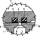
Fig. 2 has shown according to the cross-sectional plane of known technology along the collaboration region A intercepting of the import of balance cock and conveying trough with high range more.
Conveying trough 7 ends in the opening 8 that is arranged in the master cylinder body 1, and described opening 8 forms the import of conveying trough.In the piston 4 of master cylinder 1, dig out two parallel annular seats, in each seat, hold a Gask-O-Seal 9, packing seal 9 is the O RunddichtringO made of rubber normally, and it is furnished with the circle of being made by tetrafluoroethylene in most cases 10 that is used for sealing and slides.Shown in dead position, described two packing seal 9-10 are positioned at the both sides as the opening 8 of the import of conveying trough 7.When beginning during brake operation, piston 4 (towards the left side of figure) is mobile, and one of them of packing seal 9-10 crossed opening 8 and opened being communicated with between the internal volume of conveying trough 7 and master cylinder 1.In the diagram dead position, two packing seal 9-10 limit an annular space around piston, and described annular space is communicated with the inner space of conveying trough 7.Being included in liquid in the conveying trough 7 is limited to wherein whole space and is actually and can not changes, for this reason, the het expansion that produces owing to the heating of described liquid causes pressure to increase, the value that described pressure increases can apply a power to packing seal 9-10, and described power is enough to damage, discharges or extracts out packing seal.
Fig. 3 has shown along the cross-sectional plane of the collaboration region A intercepting of the import 8 of balance cock V according to the present invention and conveying trough 7 with the ratio bigger than Fig. 2.
Described conveying trough 7 still terminates in the opening 8 of master cylinder body 1, and opening 8 forms the import of conveying trough.Two parallel annular seats still are set in the piston 4 of master cylinder 1, can hold a Gask-O-Seal 9 in the annual seat (in Fig. 3, being the right side) therein, packing seal 9 is the O RunddichtringO made of rubber normally, and it is furnished with the circle of being made by tetrafluoroethylene usually 10 that is used for sealing and slides according to known technology.Another annual seat 12-13 of piston 4 holds packing seal 11, the layout of these parts is to contain the space for limiting one, described containing space is suitable for allowing hydrodynamic reciprocating sealing pad 11 under elastic condition, thereby can be positioned at the volume in the space of the packing seal side that is communicated with conveying trough 7 with significant mode increase.Especially, in the embodiment shown, packing seal 11 is O RunddichtringOs, contains space 12-13 and has the expansion section 13 that comprises packing seal 11, and extend in the part 12 that narrows down gradually.
In diagram dead position, two packing seal 9-10 and 11 both sides that are positioned at as the opening 8 of conveying trough 7 imports.In the diagram dead position, packing seal 9-10 and 11 limits an annular space around piston, and described annular space is communicated with the inner space of conveying trough 7, but this annular space is different with known technology, and it is defined in variable mode.In fact, the pressure increase that is included in the liquid in the conveying trough 7 acts on the packing seal 11 and towards the narrowed portion 12 hydrodynamic reciprocating sealing pads 11 that contain space 12-13.Compressed and the flexibly distortion by packing seal 11, it enters in the containing space 12 that narrows down and the increase of the annular space that causes being communicated with the inner space of conveying trough 7.The increase of the gross space that thermally-expansible liquid can obtain has limited described pressure to be increased.For this reason, by giving described parts suitable measure, the het expansion that liquid produces owing to heating can not produce pressure to be increased, and described pressure increase applies the power that is enough to destroy, discharge or extract out packing seal can for packing seal 9-10 and 11.
Certainly, when the reason that stopped making packing seal to move, self elasticity of packing seal will make it return to normal configuration again.Perhaps, independent springing M (schematically being shown by arrow among Fig. 3) suitably can be inserted with packing seal 11 and contain among the 12-13 of space, and when the reason that stops to make packing seal to move, the effect of described springing M will make again that packing seal 11 returns to its normal configuration.
Therefore, when implementing brake operation subsequently, conveying trough 7 is communicated with one of them individual inner space of master cylinder 1, the pressure increase of the liquid that produces owing to het expansion stops then, and the effect of the elasticity of packing seal 11 or independent springing M makes packing seal 11 recover its normal configuration again.
During by the bilateral brake of operating two brake pedals simultaneously, namely for example in the brake operation during road travels, towards another compression, valve V according to the present invention is as the common valve effect with two packing seal 9-10 and 11 1 for the pressure that produces in the master cylinder 1.
By during only operating the one-sided brake that a brake pedal obtains, namely for example during agricultural operation, do not have the balance cock interception of operated master cylinder by the pressure that is produced by the operation master cylinder by another, and it makes packing seal 11 resilient movement.As a result, take place by the increase of the stroke of operation brake pedal, but this a spot of stroke is increased under the operating conditions and can be ignored fully and not note.
Layout according to containing of the present invention space is suitable for allowing hydrodynamic reciprocating sealing pad under elastic condition, thereby increase the volume in the space that is communicated with conveying trough in remarkable mode, described layout except represent preferred example shown in can be embodied in various manners arranging.According to this example, packing seal 11 itself can have common shape, and the place one's entire reliance upon shape of the space 12-13 that holds packing seal 11 of the possibility that moves of the packing seal that causes owing to the packing seal elastic deformation.
The described space that shows in illustrative example preferably has enlarged area 13, it is arranged in described enlarged area 13 when packing seal 11 is in its minimal elastic deformation condition following time, and described space has narrowed areas 12 gradually, because the increase of packing seal 11 elastic deformations, packing seal 11 can be punctured in the described narrowed areas 12.Yet, also can select to contain other difformities in space, and can not change the result who obtains.
As an alternative, the possibility of the resilient movement of the packing seal that produces owing to the distortion of the packing seal special shape of packing seal self that can place one's entire reliance upon.In this case, do not need to contain the space and have any special tectonic.
At last, can be by be included in the possibility that the springing M that contains in the space guarantees to contain the resilient movement of packing seal in the space with packing seal 11.
Because balance cock V comprises two Gask-O-Seals, for the purposes of the present invention, have only a packing seal to have described feature and another packing seal keeps common arrangement (such as represented) just enough.Yet, also can be with feature application of the present invention to two packing seals of balance cock V.
Similarly, because have two by conveying trough 7 master cylinders 1 connected to one another, so the balance cock V that only has a master cylinder to comprise to have feature of the present invention is just enough.Yet still owing to making reason, preferably two master cylinders all are equipped with according to balance cock V of the present invention.
Should be appreciated that the present invention is not restricted to described embodiment, especially be not restricted to the embodiment that shows by example.Mentioned several possible modification in the process of describing, other modification is also in the scope that those of ordinary skills understand.Under the prerequisite that does not break away from the spirit of the present invention that is limited by the appended claims book, can carry out these and other modification and replacement by the device of technical equivalence to describe and shown example.
Claims (12)
1. balance cock (V) that is used for brake and drive system for vehicle with tow, described vehicle comprises the master cylinder (1) of two separation, independent braking for the wheel that is positioned at the vehicle both sides, described balance cock (V) comprises two Gask-O-Seal (9-10,11), described Gask-O-Seal cooperates mutually with the import (8) of the conveying trough (7) that is connected two master cylinders (1), it is characterized in that, at least one (11) of the packing seal of described balance cock (V) are accommodated in one and contain in the space (12-13), described containing space (12-13) is suitable for allowing the described packing seal of dislocation (11) under elastic condition, thereby is positioned at the volume in the space of the packing seal side that is communicated with described conveying trough (7) with significant mode increase.
2. balance cock according to claim 1 (V), it is characterized in that, described balance cock comprises a springing (M), and described springing (M) is arranged to make described packing seal (11) become its normal configuration again when the reason of described packing seal dislocation stops.
3. balance cock according to claim 2 (V) is characterized in that, described springing (M) is the member that separates with described packing seal (11).
4. balance cock according to claim 2 (V) is characterized in that, described springing (M) is the elasticity of described packing seal (11) self.
5. balance cock according to claim 1 (V), it is characterized in that, described packing seal (11) itself has roughly common shape, and because the result of the elastic deformation of described packing seal (11), the possibility of the described packing seal dislocation packing seal (11) that places one's entire reliance upon is contained in the shape in described containing space (12-13) wherein.
6. balance cock according to claim 5 (V), it is characterized in that, described packing seal contains space (12-13) and has extended area (13), described packing seal (11) is comprised in when it is in the minimal elastic deformation condition in the described extended area (13), and described containing space (12-13) has narrowed areas (12) gradually, because the increase of the elastic deformation of described packing seal (11), it can penetrate described narrowed areas gradually (12).
7. balance cock according to claim 1 (V) is characterized in that, the special shape of described packing seal (11) described packing seal (11) self because its distortion and the possibility of elasticity dislocation place one's entire reliance upon.
8. balance cock according to claim 1 (V), it is characterized in that, described packing seal contains space (12-13) and described packing seal (11) self all has specific shape, and described specific shape is suitable for allowing the elasticity dislocation of described packing seal (11) and the final volume increase in the space that is communicated with described conveying trough (7).
9. balance cock according to claim 1 (V), it is characterized in that, the possibility of the elasticity dislocation of the described packing seal (11) in the described containing space (12-13) depends on a springing (M), and described springing (M) is comprised in the described containing space (12-13) with described packing seal (11).
10. master cylinder (1) that is used for brake and drive system for vehicle with tow, described vehicle comprises the master cylinder (1) of two separation, independent braking for the wheel that is positioned at the vehicle both sides is characterized in that described master cylinder (1) comprises according to the one or more described balance cock (V) in the claim 1.
11. a vehicle that comprises the master cylinder (1) of two separation, described master cylinder (1) is characterized in that for the independent braking of the wheel that is positioned at the vehicle both sides, the individual claim 10 that meets of one of them of described master cylinder (1).
12. a vehicle that comprises the master cylinder (1) of two separation, described master cylinder (1) is characterized in that for the independent braking of the wheel that is positioned at the vehicle both sides described two master cylinders (1) all meet claim 10.
Applications Claiming Priority (3)
| Application Number | Priority Date | Filing Date | Title |
|---|---|---|---|
| ITTO2007A000908 | 2007-12-18 | ||
| IT000908A ITTO20070908A1 (en) | 2007-12-18 | 2007-12-18 | BRAKING BALANCING VALVE, FOR AN AGRICULTURAL TRACTOR OR SIMILAR VEHICLE |
| PCT/EP2008/010839 WO2009077190A2 (en) | 2007-12-18 | 2008-12-12 | A valve for the braking balancement, for a farm tractor or a similar vehicle |
Publications (2)
| Publication Number | Publication Date |
|---|---|
| CN101896381A CN101896381A (en) | 2010-11-24 |
| CN101896381B true CN101896381B (en) | 2013-09-11 |
Family
ID=40315901
Family Applications (1)
| Application Number | Title | Priority Date | Filing Date |
|---|---|---|---|
| CN2008801201316A Expired - Fee Related CN101896381B (en) | 2007-12-18 | 2008-12-12 | A valve for the braking balancement, for a farm tractor or a similar vehicle |
Country Status (7)
| Country | Link |
|---|---|
| US (1) | US8522935B2 (en) |
| EP (1) | EP2234854B1 (en) |
| CN (1) | CN101896381B (en) |
| AT (1) | ATE519642T1 (en) |
| ES (1) | ES2369959T3 (en) |
| IT (1) | ITTO20070908A1 (en) |
| WO (1) | WO2009077190A2 (en) |
Families Citing this family (9)
| Publication number | Priority date | Publication date | Assignee | Title |
|---|---|---|---|---|
| US8746423B2 (en) * | 2010-03-02 | 2014-06-10 | Hitachi Automotive Systems, Ltd. | Shock absorber |
| DE102011012730B4 (en) * | 2010-03-02 | 2021-04-29 | Hitachi Automotive Systems, Ltd. | Shock absorbers |
| IT1406552B1 (en) | 2010-09-16 | 2014-02-28 | Vhit Spa | HYDRAULIC BRAKING CONTROL DEVICE IN VEHICLES WITH DOUBLE BRAKING PEDAL |
| IT1403795B1 (en) | 2011-01-12 | 2013-10-31 | Vhit Spa | MASTER CYLINDER, METHOD TO COMMAND A DEVICE BY MEANS OF THE CYLINDER AND BALANCING DEVICE FOR A GROUP OF MASTER CYLINDERS |
| CN102431536A (en) * | 2011-11-28 | 2012-05-02 | 山东遨游汽车制动系统股份有限公司 | Balance type hydraulic pump |
| ITTO20121065A1 (en) | 2012-12-12 | 2014-06-13 | Vhit Spa | HYDRAULIC BRAKING SYSTEM FOR AGRICULTURAL AND SIMILAR TRACTORS AND METHOD OF MANAGEMENT OF THIS SYSTEM |
| EP3009315B1 (en) | 2014-10-15 | 2019-04-24 | VHIT S.p.A. | Device and method for adjusting/reducing pressure for servo controlled brakes |
| ITUB20152356A1 (en) * | 2015-07-21 | 2017-01-21 | Vhit Spa | Running balancing device for hydraulic braking systems, braking system that includes the device and method of the braking system |
| ITUB20159195A1 (en) | 2015-12-29 | 2017-06-29 | Vhit Spa | HYDRAULIC BRAKING CONTROL DEVICE FOR AGRICULTURAL AND SIMILAR VEHICLES |
Citations (5)
| Publication number | Priority date | Publication date | Assignee | Title |
|---|---|---|---|---|
| US3568441A (en) * | 1968-06-21 | 1971-03-09 | Girling Ltd | Two pedal hydraulic braking system |
| US3765690A (en) * | 1971-01-21 | 1973-10-16 | Ato Inc | Composite seal |
| US3885391A (en) * | 1972-07-07 | 1975-05-27 | Girling Ltd | Hydraulic braking system |
| US4702330A (en) * | 1983-05-14 | 1987-10-27 | Itt Industries, Inc. | Hydraulic braking and steering brake system |
| US5575484A (en) * | 1995-06-30 | 1996-11-19 | Greene, Tweed Of Delaware, Inc. | Fluid pressure activated piston return spring seal |
Family Cites Families (19)
| Publication number | Priority date | Publication date | Assignee | Title |
|---|---|---|---|---|
| GB626222A (en) | 1942-03-24 | 1949-07-12 | Fiat Spa | Improvements relating to piston packings, more particularly for vehicle brakes |
| US2420104A (en) * | 1943-07-22 | 1947-05-06 | Maytag Co | Seal guard ring |
| US2593193A (en) * | 1947-02-21 | 1952-04-15 | Edward A Rockwell | Sealing means |
| US3118682A (en) * | 1961-05-05 | 1964-01-21 | Otis Eng Co | Elastic seal with expandable back-up member |
| FR1331149A (en) * | 1961-09-19 | 1963-06-28 | Teves Gmbh Alfred | Device for polishing a rough surface |
| US3377076A (en) * | 1965-10-22 | 1968-04-09 | Bendix Corp | Return seal |
| US3455566A (en) * | 1966-03-11 | 1969-07-15 | John W Hull | Fluid sealing arrangements |
| US3531132A (en) * | 1968-07-22 | 1970-09-29 | Kidde & Co Walter | Pressure energized seal |
| US3663024A (en) * | 1970-07-02 | 1972-05-16 | Shamban & Co W S | Sealing assembly |
| US3958903A (en) * | 1972-08-14 | 1976-05-25 | Capelli Raymond A | Positive displacement device |
| US4229013A (en) * | 1979-07-02 | 1980-10-21 | Greene, Tweed & Co., Inc. | Spring seal |
| JPS571865A (en) * | 1980-06-02 | 1982-01-07 | Arai Pump Mfg Co Ltd | Roof-type groove for o-ring |
| US4342463A (en) * | 1980-10-16 | 1982-08-03 | Green, Tweed & Co., Inc. | Spring seal |
| JPS57167563A (en) * | 1981-04-06 | 1982-10-15 | Nissan Motor Co Ltd | Sealing device |
| FR2590641B1 (en) * | 1985-11-25 | 1989-07-13 | Snecma | COMPOSITE SEALING DEVICE |
| US5113747A (en) * | 1989-01-23 | 1992-05-19 | Pignerol Herve Y | High pressure piston sealing system and method of its assembly |
| US5143382A (en) * | 1991-03-04 | 1992-09-01 | W. S. Shamban & Company | Pressure relieving slipper seal system |
| US6938901B2 (en) * | 2000-12-26 | 2005-09-06 | Toyota Jidosha Kabushiki Kaisha | Combustion gas seal for injector and sealing structure with the combustion gas seal |
| US7793944B2 (en) * | 2004-12-28 | 2010-09-14 | Nok Corporation | Sealing device |
-
2007
- 2007-12-18 IT IT000908A patent/ITTO20070908A1/en unknown
-
2008
- 2008-12-12 EP EP08862214A patent/EP2234854B1/en active Active
- 2008-12-12 CN CN2008801201316A patent/CN101896381B/en not_active Expired - Fee Related
- 2008-12-12 ES ES08862214T patent/ES2369959T3/en active Active
- 2008-12-12 US US12/744,705 patent/US8522935B2/en not_active Expired - Fee Related
- 2008-12-12 AT AT08862214T patent/ATE519642T1/en not_active IP Right Cessation
- 2008-12-12 WO PCT/EP2008/010839 patent/WO2009077190A2/en active Application Filing
Patent Citations (5)
| Publication number | Priority date | Publication date | Assignee | Title |
|---|---|---|---|---|
| US3568441A (en) * | 1968-06-21 | 1971-03-09 | Girling Ltd | Two pedal hydraulic braking system |
| US3765690A (en) * | 1971-01-21 | 1973-10-16 | Ato Inc | Composite seal |
| US3885391A (en) * | 1972-07-07 | 1975-05-27 | Girling Ltd | Hydraulic braking system |
| US4702330A (en) * | 1983-05-14 | 1987-10-27 | Itt Industries, Inc. | Hydraulic braking and steering brake system |
| US5575484A (en) * | 1995-06-30 | 1996-11-19 | Greene, Tweed Of Delaware, Inc. | Fluid pressure activated piston return spring seal |
Also Published As
| Publication number | Publication date |
|---|---|
| EP2234854B1 (en) | 2011-08-10 |
| ITTO20070908A1 (en) | 2009-06-19 |
| CN101896381A (en) | 2010-11-24 |
| US20100300823A1 (en) | 2010-12-02 |
| WO2009077190A2 (en) | 2009-06-25 |
| WO2009077190A3 (en) | 2009-09-03 |
| ATE519642T1 (en) | 2011-08-15 |
| ES2369959T3 (en) | 2011-12-09 |
| EP2234854A2 (en) | 2010-10-06 |
| US8522935B2 (en) | 2013-09-03 |
Similar Documents
| Publication | Publication Date | Title |
|---|---|---|
| CN101896381B (en) | A valve for the braking balancement, for a farm tractor or a similar vehicle | |
| US9205821B2 (en) | Brake system for motor vehicles | |
| ATE331639T1 (en) | HYDROPNEUMATIC SUSPENSION DEVICE | |
| US4422293A (en) | Closed-center hydraulic servo apparatus | |
| US9421954B2 (en) | Hydraulic braking system for farm tractors or the like and method of managing such system | |
| EP2038153A2 (en) | Operating apparatus | |
| US20120137674A1 (en) | Brake system with master cylinder, disengaged from the brake pedal, and hydraulic brake booster | |
| DE102011081601A1 (en) | Actuation module for a brake system | |
| CN102574517A (en) | Master cylinder assembly for balancing braking systems of an agricultural vehicle | |
| GB1380614A (en) | Hydraulic braking systems | |
| US6322162B2 (en) | Actuating device for an electrohydraulic vehicle brake system | |
| GB1374548A (en) | Tandem axle suspension | |
| US10434999B2 (en) | Stroke controlled balancing device for a hydraulic braking system, braking system comprising the device and method of operating the braking system | |
| WO2006118576A3 (en) | Vehicle roll control system with self-centering actuator | |
| CN101392840B (en) | Valve | |
| CN103826946A (en) | Master brake cylinder for a vehicle brake system and method for operating a master brake cylinder | |
| CN109923010A (en) | Valve module, braking system and the method for running valve module | |
| US20180281551A1 (en) | Suspension system | |
| KR102507712B1 (en) | 3-Way Solenoid Valve And Brake System for Vehicle Including Same | |
| US4832417A (en) | Brake system | |
| US5394701A (en) | Brake valve with prefill chamber unloading valve | |
| US3766735A (en) | Brake booster and master cylinder assembly | |
| CN110789509A (en) | Mechanical double-cavity balance brake valve | |
| US3880185A (en) | Control for hydraulic systems | |
| US3622207A (en) | Hydraulic translating and valving unit |
Legal Events
| Date | Code | Title | Description |
|---|---|---|---|
| C06 | Publication | ||
| PB01 | Publication | ||
| C10 | Entry into substantive examination | ||
| SE01 | Entry into force of request for substantive examination | ||
| C14 | Grant of patent or utility model | ||
| GR01 | Patent grant | ||
| CF01 | Termination of patent right due to non-payment of annual fee | ||
| CF01 | Termination of patent right due to non-payment of annual fee |
Granted publication date: 20130911 Termination date: 20171212 |