CN101886036B - Full-ecological, intelligent and multifunctional environmental protection methane generator - Google Patents
Full-ecological, intelligent and multifunctional environmental protection methane generator Download PDFInfo
- Publication number
- CN101886036B CN101886036B CN2010102395638A CN201010239563A CN101886036B CN 101886036 B CN101886036 B CN 101886036B CN 2010102395638 A CN2010102395638 A CN 2010102395638A CN 201010239563 A CN201010239563 A CN 201010239563A CN 101886036 B CN101886036 B CN 101886036B
- Authority
- CN
- China
- Prior art keywords
- tank
- natural pond
- methane
- sensor
- biogas
- Prior art date
- Legal status (The legal status is an assumption and is not a legal conclusion. Google has not performed a legal analysis and makes no representation as to the accuracy of the status listed.)
- Expired - Fee Related
Links
Images

Classifications
-
- C—CHEMISTRY; METALLURGY
- C12—BIOCHEMISTRY; BEER; SPIRITS; WINE; VINEGAR; MICROBIOLOGY; ENZYMOLOGY; MUTATION OR GENETIC ENGINEERING
- C12M—APPARATUS FOR ENZYMOLOGY OR MICROBIOLOGY; APPARATUS FOR CULTURING MICROORGANISMS FOR PRODUCING BIOMASS, FOR GROWING CELLS OR FOR OBTAINING FERMENTATION OR METABOLIC PRODUCTS, i.e. BIOREACTORS OR FERMENTERS
- C12M21/00—Bioreactors or fermenters specially adapted for specific uses
- C12M21/04—Bioreactors or fermenters specially adapted for specific uses for producing gas, e.g. biogas
-
- C—CHEMISTRY; METALLURGY
- C12—BIOCHEMISTRY; BEER; SPIRITS; WINE; VINEGAR; MICROBIOLOGY; ENZYMOLOGY; MUTATION OR GENETIC ENGINEERING
- C12M—APPARATUS FOR ENZYMOLOGY OR MICROBIOLOGY; APPARATUS FOR CULTURING MICROORGANISMS FOR PRODUCING BIOMASS, FOR GROWING CELLS OR FOR OBTAINING FERMENTATION OR METABOLIC PRODUCTS, i.e. BIOREACTORS OR FERMENTERS
- C12M23/00—Constructional details, e.g. recesses, hinges
- C12M23/38—Caps; Covers; Plugs; Pouring means
-
- C—CHEMISTRY; METALLURGY
- C12—BIOCHEMISTRY; BEER; SPIRITS; WINE; VINEGAR; MICROBIOLOGY; ENZYMOLOGY; MUTATION OR GENETIC ENGINEERING
- C12M—APPARATUS FOR ENZYMOLOGY OR MICROBIOLOGY; APPARATUS FOR CULTURING MICROORGANISMS FOR PRODUCING BIOMASS, FOR GROWING CELLS OR FOR OBTAINING FERMENTATION OR METABOLIC PRODUCTS, i.e. BIOREACTORS OR FERMENTERS
- C12M29/00—Means for introduction, extraction or recirculation of materials, e.g. pumps
- C12M29/04—Filters; Permeable or porous membranes or plates, e.g. dialysis
-
- C—CHEMISTRY; METALLURGY
- C12—BIOCHEMISTRY; BEER; SPIRITS; WINE; VINEGAR; MICROBIOLOGY; ENZYMOLOGY; MUTATION OR GENETIC ENGINEERING
- C12M—APPARATUS FOR ENZYMOLOGY OR MICROBIOLOGY; APPARATUS FOR CULTURING MICROORGANISMS FOR PRODUCING BIOMASS, FOR GROWING CELLS OR FOR OBTAINING FERMENTATION OR METABOLIC PRODUCTS, i.e. BIOREACTORS OR FERMENTERS
- C12M43/00—Combinations of bioreactors or fermenters with other apparatus
- C12M43/02—Bioreactors or fermenters combined with devices for liquid fuel extraction; Biorefineries
-
- C—CHEMISTRY; METALLURGY
- C12—BIOCHEMISTRY; BEER; SPIRITS; WINE; VINEGAR; MICROBIOLOGY; ENZYMOLOGY; MUTATION OR GENETIC ENGINEERING
- C12M—APPARATUS FOR ENZYMOLOGY OR MICROBIOLOGY; APPARATUS FOR CULTURING MICROORGANISMS FOR PRODUCING BIOMASS, FOR GROWING CELLS OR FOR OBTAINING FERMENTATION OR METABOLIC PRODUCTS, i.e. BIOREACTORS OR FERMENTERS
- C12M47/00—Means for after-treatment of the produced biomass or of the fermentation or metabolic products, e.g. storage of biomass
- C12M47/10—Separation or concentration of fermentation products
-
- C—CHEMISTRY; METALLURGY
- C12—BIOCHEMISTRY; BEER; SPIRITS; WINE; VINEGAR; MICROBIOLOGY; ENZYMOLOGY; MUTATION OR GENETIC ENGINEERING
- C12M—APPARATUS FOR ENZYMOLOGY OR MICROBIOLOGY; APPARATUS FOR CULTURING MICROORGANISMS FOR PRODUCING BIOMASS, FOR GROWING CELLS OR FOR OBTAINING FERMENTATION OR METABOLIC PRODUCTS, i.e. BIOREACTORS OR FERMENTERS
- C12M47/00—Means for after-treatment of the produced biomass or of the fermentation or metabolic products, e.g. storage of biomass
- C12M47/14—Drying
-
- Y—GENERAL TAGGING OF NEW TECHNOLOGICAL DEVELOPMENTS; GENERAL TAGGING OF CROSS-SECTIONAL TECHNOLOGIES SPANNING OVER SEVERAL SECTIONS OF THE IPC; TECHNICAL SUBJECTS COVERED BY FORMER USPC CROSS-REFERENCE ART COLLECTIONS [XRACs] AND DIGESTS
- Y02—TECHNOLOGIES OR APPLICATIONS FOR MITIGATION OR ADAPTATION AGAINST CLIMATE CHANGE
- Y02E—REDUCTION OF GREENHOUSE GAS [GHG] EMISSIONS, RELATED TO ENERGY GENERATION, TRANSMISSION OR DISTRIBUTION
- Y02E50/00—Technologies for the production of fuel of non-fossil origin
- Y02E50/30—Fuel from waste, e.g. synthetic alcohol or diesel
Abstract
The invention relates to a full-ecological, intelligent and multifunctional environmental protection methane generator which comprises a tank body, wherein an anaerobic digester, a solid-liquid separating chamber, a methane liquid filter chamber, a methane liquid distillation chamber, a drying chamber, a stack retting tank, a water storage tank and an overflow tank are distributed from top to bottom in the tank body, wherein the anaerobic digester is positioned between a top cover of the tank body and a funnel-shaped bottom plate; the solid-liquid separating chamber is positioned between the funnel-shaped bottom plate and a methane residue separating screen; the methane liquid filter chamber is positioned between the methane residue separating screen and the methane liquid filter screen at the tail end in the tank body; the methane liquid distillation chamber is positioned between the methane liquid filter screen at the tail end and a top plate of the drying chamber in the tank body; the drying chamber is positioned below the methane liquid distillation chamber in the tank body; and the stack retting tank, the water storage tank and the overflow tank are positioned below the tank body. The invention improves the gas production rate, shortens the gas production cycle, thoroughly solves the problem of serious pollution of waste residue and waste liquid after methane is fermented traditionally, and can produce a plurality of products such as methane, carbon dioxide, methanol, organic composite fertilizer and organic pesticide.
Description
Technical field
The present invention relates to a kind of biogas generator.
Background technology
Process human and animal excreta with methane engineering technology, can effectively solve life in the countryside energy problem, can obtain again the required organic fertilizer of agriculture production, improve Rural Human Settlements, have good economy, ecology and social benefit.Also there is following problem in built biogas generator at present:
1, directly feeds intake to methane-generating pit, cause easily environmental pollution;
2, the pre-ferment of state of nature needs 7-10 days, overlong time;
3, inoculation bacterium breeding potential is low, and the aerogenesis cycle is long, and factor of created gase is low;
4, there is the difficult problem of running, leak gas in the connecting pipeline between each reacting tank body;
5, the biogas fermentation layer by strong stirring after factor of created gase low;
6, biogas production is temperature required relies on natural energy resources fully and manually promotes temperature, brings easily secondary pollution;
7, the complete rear waste residue of biogas fermentation, waste liquid serious environment pollution.
Summary of the invention
The purpose of this invention is to provide a kind of complete ecological intelligence, multifunctional environmental protection methane generator, solve the technical problems such as existing biogas generator factor of created gase is low, cycle length, contaminate environment.
For achieving the above object, the present invention adopts following technical scheme:
This complete ecological intelligence, multifunctional environmental protection methane generator comprise tank body, and tank interior is distributed with anaeroic digestor, solid-liquid separation chamber, natural pond liquid filtration chamber, natural pond liquid stilling chamber, drying shed, stack retting tank, water tank and weir tank from top to bottom;
Anaeroic digestor is between tank body top cover and doline base plate, and the tank body top cover outside is connected with the additive tank that passes into anaeroic digestor; Temperature sensor, additive sensor, PH sensor, humidity sensor, water level limiter, concentration sensor, pressure transmitter, biogas sensor and volume sensor are installed in the anaeroic digestor; Have useless slag bleed valve doorway, natural pond on the doline base plate, anaeroic digestor inside vertically is connected with pre-fermentation tube, glaur drainage tube, hydraulic pipe, collecting methane supervisor and weir tank and sucks the incrustation transfer lime with stirrer in the anaeroic digestor; Pre-fermentation tube is connected between anaeroic digestor top and the stack retting tank top; The glaur drainage tube is connected between anaeroic digestor bottom and the stack retting tank; Collecting methane supervisor upper end is connected in anaeroic digestor top, and the slag bleed valve doorway, useless natural pond that doline base plate center is passed in the lower end is connected with stack retting tank, water tank and weir tank through the collecting methane arm respectively; The hydraulic pipe upper end is connected with spray header with two arms on one of them arm, and spray header is located at collecting methane main pipe line oblique upper, and the hydraulic pipe lower end is connected with water tank; Weir tank suction incrustation transfer lime is connected in anaeroic digestor top and is connected with weir tank;
The solid-liquid separation chamber is between funnel type base plate and natural pond slag separate mesh, and natural pond slag separate mesh is connected in inner tank wall, and slag separate mesh center, natural pond is equipped with natural pond slag discharging valve port, and funnel type base plate lower surface is connected with temperature sensor and capacity sensor;
Liquid filtration chamber, natural pond is between the natural pond of tank interior slag separate mesh and terminal natural pond liquid filtering net, tank interior is connected with at least natural pond liquid filtering net at natural pond slag separate mesh between the liquid filtering net of terminal natural pond, natural pond slag discharging valve port is connected with natural pond slag discharge-channel downwards and between the drying shed top board, is the little slag spiral of row's natural pond liquid groove between natural pond liquid filtering net and the natural pond slag discharge-channel;
Natural pond liquid stilling chamber is between the terminal natural pond liquid filtering net and drying shed top board of tank interior, and tank wall has machine agricultural chemicals discharging valve port on liquid stilling chamber top, natural pond; Slag separate chamber, two natural ponds drainage tube is arranged, and wherein slag separate chamber, natural pond drainage tube is connected between liquid stilling chamber bottom, natural pond and the stack retting tank, and another slag separate chamber, root natural pond drainage tube is connected between liquid stilling chamber bottom, natural pond and the water tank;
Drying shed is positioned at the liquid stilling chamber below, natural pond of tank interior, outer wall of drying room is equipped with distillation oven dry heating installation, drying shed inside is fixed with natural pond slag splitter column over against natural pond slag discharge-channel, drying shed base plate center has drying shed discharging fertilizer valve port, and drying shed top board lower surface is equipped with humidity sensor and temperature sensor;
The stack retting tank is positioned at tank body lower part, there is stirrer stack retting tank inside, also be provided with temperature sensor, degradation inhibitor sensor, water level limiter, pH value sensor, biogas detector in the stack retting tank, the coiling of stack retting tank wall has the internal recycle caliduct, is connected with the degraded tank on the stack retting top ends of cans;
Water tank is positioned at tank body lower part, be communicated with stack retting tank middle part by pipeline, water tank inside is closed on mouth of pipe place and is provided with the water tank impeller pump, also is provided with biogas sensor, PH sensor and water level sensor in the water tank, is connected with the water tank degradation agents tank that passes into tank inside on the water tank top cover;
Weir tank is positioned at tank body lower part, and weir tank is connected with water tank by the weir tank pipe connecting;
The toilet toilet of tank body outside, hand basin, be separately installed with toilet toilet infrared eye on the rubbish container, the hand basin infrared eye, stalk, stalk, the rubbish infrared eye, the toilet toilet, hand basin, rubbish container all is connected with solid-liquid separation tank, and at the main pipe line that connects the siphon impeller pump is installed, solid material pulverizer is installed in the solid-liquid separation tank, solid-liquid separation tank is connected with the stack retting tank of tank interior through solid pipeline, solid pipeline is provided with solid material settling bath, solid-liquid separation tank is connected with the water tank of tank interior through fluid pipeline, and fluid pipeline is provided with the liquid precipitation groove;
The tank body top cover outside is equipped with aerogenerator and solar water heater, and the solar water heater electrically heated rod is equipped with in solar water heater inside; Tank wall is distributed with caliduct, and is connected with external hot-water valve, and the biogas boiler is installed in the tank body, and the biogas boiler is connected with the methane boiler flue; Devulcanizer also is installed on the tank body, devulcanizer one end is connected with the desulfurizing machine biogas pipeline of sending into that passes into anaeroic digestor, the other end is connected with carbonic acid gas methane purification machine, after carbonic acid gas methane purification machine is purified by carbonic acid gas biogas pipeline respectively with methane combustion furnace, biogas generator connects; Tank base also is equipped with secondary battery and invertor potentiostat switchboard.
Described tank body top cover inboard also is equipped with high pressure blowpipe behind control biogas air blowing sensor and the Marsh gas compression, and to suck the transfer lime of forming a scab suitable for reading relative for the air outlet of high pressure blowpipe and weir tank behind the Marsh gas compression; The air intake vent of high pressure blowpipe is connected with the air outlet of air compressor behind the Marsh gas compression, the air intake vent of air compressor respectively with collecting methane supervisor top be connected desulfurizing machine biogas pipeline bottom and be connected.
Described tank body is metal can or glass reinforced plastic tank body.
Described tank wall also is equipped with photovoltaic silicon single crystal plate.
Slag bleed valve doorway, described useless natural pond is distributed in center and the top, two side of doline base plate.
Described natural pond slag discharge-channel sidewall has natural pond liquid particulate slag bleed valve in natural pond liquid filtering net top endways.
Also be connected with biogas pipeline after the desulfurization on the pipeline between described devulcanizer and the carbonic acid gas methane purification machine.
Described sending into is connected with not desulfurization biogas pipeline on the desulfurizing machine biogas pipeline.
Compared with prior art the present invention has following characteristics and beneficial effect:
1, adopt the split charging, anaeroic digestor, solid-liquid separation chamber, natural pond liquid filtration chamber etc. are case pot type integral structure, can produce: biogas, carbonic acid gas, methyl alcohol, compoiste fertilizer, a plurality of products of organic pesticide.
2, split siphon opening for feed: charging sucked in the pulverizer stir, be transported to the stack retting tank by the sealing vacuum pipe and carry out pre-ferment, solved the environmental pollution that methane-generating pit feeds intake and causes.
3, stack retting retort: the biogas material of opening for feed input is carried out chemistry mix, Pressurized-heated accelerates the decomposition of marsh gas raw materials, makes the 7-10 days time shorten to 1 day of the pre-ferment of original state of nature.
4, drainage glaur, natural pond liquid inoculum under the anaerobism have improved inoculation bacterium breeding potential, have shortened the aerogenesis cycle, have improved factor of created gase.
5, utilize the waste heat that keeps anaeroic digestor fermentation constant temperature, natural pond waste residue, the liquid that has fermented is carried out solid, liquid separate, filter, distill, dry, directly produce industrial works, thoroughly solved the difficult problem of the complete rear waste residue of traditional biogas fermentation, waste liquid severe contamination.
6, the biogas of weir tank, drying shed, solid-liquid separation chamber, water tank, the generation of stack retting tank is collected by the intercommunication pipeline, has solved race, a gas leakage difficult problem, has improved the biogas gas efficiency.
7, the overflow substance of weir tank, water tank shunting anaeroic digestor has been slowed down anaeroic digestor pressure, has also strengthened the exchange of anaerobism kind bacterium, has also improved factor of created gase.
8, the renewable energy resources heat that the biogas that utilizes wind energy, sun power, solar photovoltaic and self device to produce produces forms an internal heat circulation, need for the heat energy that self installs, make this device keep temperature-constant operation, solved the temperature required secondary pollution that relies on natural energy resources and artificial lifting temperature to bring fully of traditional biogas production.
9, utilize high pressure air pressure after the Marsh gas compression machine compression, gaseous tension is carried out in fermented product upper strata incrustation in the anaeroic digestor to be smashed, the incrustation that while air pressure smashes is taken advantage of a situation and is flowed to the siphon port limit that sets, sending into the weir tank scab by siphon power upstream line processes, incrustation after the processing is delivered to the stack retting tank and is dissolved in pre-ferment material, again be transported in the anaeroic digestor and ferment, this processing without strong stirring formed a scab, and solved the fermentation layer by the low problem of factor of created gase behind the strong stirring.
10, wind-force, photovoltaic, self-produced marsh gas power generation, renewable source of energy generation are realized self-sufficiency, and biogas production need not rely on external power supply, really reach one of ecological, environmental protective and improve the Production Flow Chart of the product biogas integration of industry.
Description of drawings
The present invention will be further described in detail below in conjunction with accompanying drawing.
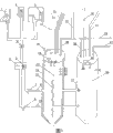
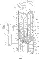
Fig. 1 is the structural representation of tank body pan feeding part.
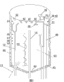
Fig. 2 is the structural representation of anaeroic digestor.
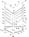
Fig. 3 is the structural representation of solid-liquid separation chamber, natural pond liquid filtration chamber, natural pond liquid stilling chamber, drying shed.
Fig. 4 is the structural representation that part is removed in incrustation.
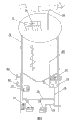
Fig. 5 is the structural representation of internal recycle circuit and heat energy pipeline.
Fig. 6 is that biogas anaerobic fermentation production principle of the present invention is always schemed
Reference numeral: 1-toilet toilet infrared eye, 2-hand basin infrared eye, the 3-stalk, stalk, the rubbish infrared eye, 4-siphon impeller pump, 5-expects pulverizer admittedly, the 6-solid-liquid separation tank, 7-expects settling bath admittedly, 8-liquid precipitation groove, the 9-solid pipeline, the 10-fluid pipeline, slag separate chamber, 11-natural pond drainage tube, the pre-fermentation tube of 12-, 13-glaur drainage tube, the 14-hydraulic pipe, 15-collecting methane supervisor, the 16-tank of degrading, 17-water tank impeller pump, 18-internal recycle caliduct, the 19-temperature sensor, 20-degradation inhibitor sensor, the 21-water level limiter, 22-PH value sensor, the 23-stirrer, 24-biogas detector, 25-stack retting tank, the 26-water tank, 27-leads to the weir tank pipeline, 28-collecting methane arm, 29-water tank degradation agents tank, the 30-PH sensor, 31-biogas sensor, the 32-water level sensor, 33-additive sensor, the 34-additive tank, the 35-humidity sensor, the 36-spray header, the 37-concentration sensor, the 38-pressure transmitter, the 39-volume sensor, 40-siphon incrustation import, 41-doline base plate, 42-biogas air outlet, the 43-slag bleed valve doorway, natural pond of giving up, the 44-caliduct, 45-biogas residue liquid separate mesh, 46-natural pond liquid filtering net, the terminal natural pond of 47-liquid filtering net, 48-natural pond liquid particulate slag bleed valve, 49-natural pond slag discharging valve port, 50-organic pesticide discharging valve port, the little slag spiral of 51-row's natural pond liquid groove, the 52-capacity sensor, 53-distillation natural pond liquid chamber, liquid filtration chamber, 54-natural pond, 55-solid-liquid separation chamber, 56-natural pond slag discharge-channel, 57-distillation oven dry heating installation, 58-drying shed discharging fertilizer valve port, 59-natural pond slag splitter column, the 60-humidity sensor, the 61-drying shed, the 62-heat detector, the 63-anaeroic digestor, high pressure blowpipe behind the 64-Marsh gas compression, 65-sends into the desulfurizing machine biogas pipeline, 66-control biogas air blowing sensor, the 67-air compressor, the 68-weir tank sucks the incrustation transfer lime, biogas pipeline after the 69-desulfurization, 70-biogas combustion boiler, the 71-devulcanizer, the 72-solar water heater, the 73-weir tank, 74-solar water heater electrically heated rod, 75-photovoltaic silicon single crystal plate, the 76-biogas generator, the 77-secondary battery, 78-carbonic acid gas methane purification machine, biogas pipeline after the 79-carbonic acid gas is purified, the external hot-water valve of 80-, 81-invertor potentiostat switchboard, 82-methane boiler flue, the 83-aerogenerator, 84-is the desulfurization biogas pipeline not.
Embodiment
Embodiment is referring to shown in Fig. 1-6, this complete ecological intelligence, multifunctional environmental protection methane generator, comprise tank body, tank interior is distributed with anaeroic digestor 63, solid-liquid separation chamber 55, natural pond liquid filtration chamber 54, natural pond liquid stilling chamber 53, drying shed 61, stack retting tank 25, water tank 26 and weir tank 73 from top to bottom.
Referring to shown in Figure 1, the toilet toilet of tank body outside, hand basin, be separately installed with toilet toilet infrared eye 1 on the rubbish container, hand basin infrared eye 2, stalk, stalk, rubbish infrared eye 3, the toilet toilet, hand basin, rubbish container all is connected with solid-liquid separation tank 6, and at the main pipe line that connects siphon impeller pump 4 is installed, solid material pulverizer 5 is installed in the solid-liquid separation tank 6, solid-liquid separation tank 6 is connected with the stack retting tank 25 of tank interior through solid pipeline 9, solid pipeline 9 is provided with solid material settling bath 7, solid-liquid separation tank 6 is connected with the water tank 26 of tank interior through fluid pipeline 10, and fluid pipeline 10 is provided with liquid precipitation groove 8.
Weir tank 73 is positioned at tank body lower part, and weir tank 73 is connected with water tank 26 by weir tank pipe connecting 27.
Referring to shown in Figure 2, anaeroic digestor 63 is between tank body top cover and doline base plate 41, and the tank body top cover outside is connected with the additive tank 34 that passes into anaeroic digestor; Temperature sensor 19, additive sensor 33, PH sensor 30, humidity sensor 35, water level limiter 21, concentration sensor 37, pressure transmitter 38, biogas sensor 31 and volume sensor 39 are installed in the anaeroic digestor; Have useless slag bleed valve doorway, natural pond 43 on the doline base plate, useless slag bleed valve doorway, natural pond 43 is distributed in center and the top, two side of doline base plate; Anaeroic digestor inside vertically is connected with pre-fermentation tube 12, glaur drainage tube 13, hydraulic pipe 14, collecting methane supervisor 15 and weir tank and sucks incrustation transfer lime 68 with stirrer 23 in the anaeroic digestor; Pre-fermentation tube 12 is connected between anaeroic digestor top and stack retting tank 25 tops; Glaur drainage tube 13 is connected between anaeroic digestor bottom and the stack retting tank; Collecting methane is responsible for 15 upper ends and is connected in anaeroic digestor top, is connected with weir tank through collecting methane arm and stack retting tank 25, water tank 26 respectively and is connected in the slag bleed valve doorway, useless natural pond 43 that doline base plate 41 centers are passed in the lower end; Hydraulic pipe 14 upper ends are connected with spray header 36 with two arms on one of them arm, spray header 36 is located at collecting methane main pipe line 15 oblique uppers, and hydraulic pipe 14 lower ends are connected with water tank 26; Weir tank suction incrustation transfer lime 68 is connected in anaeroic digestor top and is connected with weir tank 73.
Referring to shown in Figure 3, solid-liquid separation chamber 55 is between funnel type base plate 41 and natural pond slag separate mesh 45, natural pond slag separate mesh is connected in inner tank wall, and slag separate mesh 45 centers, natural pond are equipped with natural pond slag discharging valve port 49, and funnel type base plate 41 lower surfaces are connected with temperature sensor 19 and capacity sensor 52.
Referring to shown in Figure 3, liquid filtration chamber 54, natural pond is between the natural pond of tank interior slag separate mesh 45 and terminal natural pond liquid filtering net 47, tank interior is connected with at least natural pond liquid filtering net 46 at natural pond slag separate mesh 45 between the liquid filtering net of terminal natural pond, natural pond slag discharging valve port 49 is connected with natural pond slag discharge-channel 56 downwards and between the drying shed top board, is the little slag spiral of row's natural pond liquid groove 51 between natural pond liquid filtering net 46 and the natural pond slag discharge-channel 56; Natural pond slag discharge-channel 56 sidewalls endways natural pond liquid filtering net 47 tops have natural pond liquid particulate slag bleed valve 48.
Referring to shown in Figure 3, natural pond liquid stilling chamber 53 is between the terminal natural pond liquid filtering net 47 and drying shed 61 top boards of tank interior, and tank wall has machine agricultural chemicals discharging valve port 50 on liquid stilling chamber 53 tops, natural pond; Slag separate chamber, two natural ponds drainage tube 11 is arranged, and wherein slag separate chamber, natural pond drainage tube is connected between liquid stilling chamber 53 bottoms, natural pond and the stack retting tank 25, and another slag separate chamber, root natural pond drainage tube is connected between liquid stilling chamber 53 bottoms, natural pond and the water tank 26.
Referring to shown in Figure 3, drying shed 61 is positioned at liquid stilling chamber 53 belows, natural pond of tank interior, drying shed 61 outer walls are equipped with distillation oven dry heating installation 57, drying shed 61 inside are fixed with natural pond slag splitter column 59 over against natural pond slag discharge-channel 56, drying shed 61 base plate centers have drying shed discharging fertilizer valve port 58, and drying shed 61 top board lower surfaces are equipped with humidity sensor 60 and temperature sensor 62.
Referring to shown in Figure 4, described tank body top cover inboard also is equipped with high pressure blowpipe 64 behind control biogas air blowing sensor 66 and the Marsh gas compression, and to suck the transfer lime 68 of forming a scab suitable for reading relative for the air outlet of high pressure blowpipe 64 and weir tank behind the Marsh gas compression; The air intake vent of high pressure blowpipe 64 is connected with the air outlet of air compressor 67 behind the Marsh gas compression, and the air intake vent of air compressor 67 is responsible for 15 tops and is connected desulfurizing machine biogas pipeline 65 bottoms and is connected with collecting methane respectively.
Referring to shown in Figure 5, the tank body top cover outside is equipped with aerogenerator 83 and solar water heater 72, and solar water heater electrically heated rod 74 is equipped with in solar water heater 72 inside; Tank wall also is equipped with photovoltaic silicon single crystal plate 75; Tank wall is distributed with caliduct 44, and is connected with external hot-water valve 80, and biogas boiler 70 is installed in the tank body, and biogas boiler 70 is connected with methane boiler flue 82; Devulcanizer 71 also is installed on the tank body, devulcanizer 71 1 ends are connected with the desulfurizing machine biogas pipeline 65 of sending into that passes into anaeroic digestor 63, the other end is connected with carbonic acid gas methane purification machine 78, after carbonic acid gas methane purification machine 78 is purified by carbonic acid gas biogas pipeline 79 respectively with methane combustion furnace 70, biogas generator 76 connects; Tank base also is equipped with secondary battery 77 and invertor potentiostat switchboard 81.
Referring to shown in Figure 6, described sending into is connected with not desulfurization biogas pipeline 84 on the desulfurizing machine biogas pipeline 65.Also be connected with biogas pipeline 69 after the desulfurization on the pipeline between devulcanizer 71 and the carbonic acid gas methane purification machine 78.
Working process of the present invention is as follows:
One, the built-in infrared beam interruption detector of hydrocone type opening for feed, receive that fermenting marsh gas material has entered siphon opening for feed signal after, automatic conducting opening for feed impeller pump to the stack retting tank methane conveying fermentation material closed conduct, crushing material electromechanical source.The powerful suction that impeller pump produces, the fermenting marsh gas material of opening for feed is drawn into that opening for feed is transported to the stack retting tank transport pipe, carries out solid-liquid separation in fermenting marsh gas material solid-water separation tank, biogas fermentation solid materials after dehydration, the pulverizer that enters in the closed conduct is pulverized, then the impeller pump by the stack retting tank sucks in the stack retting tank the pre-stack retting flow process of fermenting.The isolated water of biogas fermentation thing after the filtration by the water tank impeller pump through solid-water separation tank to the water tank closed conduct, the suction water tank, the inoculation natural pond liquid that drains into water tank with natural pond liquid separate chamber mixes, after producing anerobe, be transported to anaeroic digestor fermented liq and inoculation natural pond fluid strain, a small amount of part, stack retting tank domestic demand inoculation natural pond liquid is extracted by this tank.
Two, enter the pre-ferment material of stack retting tank after pulverizing, beginning the first pre-fermentation flow process: degradation inhibitor sensor conducts electronic valve switch, with my unique formula: impact produces chemical substance, the plant degradation of anerobe growth and processes.Pre-fermentation material after the degraded, after no longer affecting the growth of anerobe, water level limiter 23 conducting water receiver impeller pumps in the tank, water (containing natural pond liquid inoculum) suction stack retting tank with water tank carries out concentration and blends, simultaneously, glaur drainage tube Mgs in the anaerobic digestion phase, also by the sensor conducts power supply of stack retting tank, open drainage anaeroic digestor inoculation glaur, above two power supplys of autoshutdown behind the water level limiter fullcharging.Heat detector is according to the temperature adjusting heating installation electromagnetic valve of measuring, and by internal recycle caliduct release of heat, it is temperature required to reach pre-fermentation material fermentation with temperature.Suitable temperature shoots up the interior anerobe of stack retting tank, pH value sensor in the tank detects pH value by the growth acid of anerobe, the change of basicity, stirrer is pressed setting data to be opened, carry out the pre-fermentation material stirring in the tank, anti-caking, ventilation, grow up at a high speed by stirring anerobe, biogas produces, after the biogas monitoring sensor is measured biogas and is acquired a certain degree, unlatching is carried pre-fermentation switch to anaeroic digestor, to possess the fermentation methane material and be sent in the anaeroic digestor to anaeroic digestor inner sealing pipeline by the stack retting tank, formal fermentation produces biogas.
Three, the water that separates after filtering from fermenting marsh gas material, by the water tank impeller pump, through fermenting marsh gas material solid-liquid separation pond to water tank closed conduct suction water tank.After the water level limit sensors monitors the water that is entered by opening for feed in the water tank, conducting is by the degraded washing powder of my preparation, pesticide inhibitor tank switch power supply, carry out degradation treatment, charging saliva through degradation treatment, grow within a certain period of time anerobe, the PH Sensor monitoring is to growing anerobe acid, after base number reached the aerogenesis standard, conducting natural pond waste residue was consolidated-the liquid separate chamber, was deposited in the natural pond liquid drainage pipe electromagnetic switch of separate chamber's lowest layer, to water tank discharging inoculation natural pond liquid, water level sensor in the water tank is filled water tank according to set amount, and two kinds of water mixed fermentations grow rapidly anerobe, the beginning aerogenesis, the biogas Sensor monitoring is behind biogas in the tank, and conducting is carried to anaeroic digestor, the separately impeller pump signal of stack retting tank discharging, for anaeroic digestor and stack retting tank, assign the transportation instruction.
Four, pre-fermentation material impeller pump is carried in the startup of anaeroic digestor inner sensor from the stack retting tank to anaeroic digestor, water tank is carried water impeller pump power switch, but with pre-ferment with aerogenesis biogas material, carry out fermentation gas in the inoculation natural pond liquid suction anaeroic digestor, warming is according to measuring heating pipeline heat flux in the temperature adjusting anaeroic digestor, ensure fermentation constant temperature, additive sensor conducts valve switch spraying additive, humidity sensor sprays by shower nozzle according to the humidity conducting water tank impeller pump that measures, the concentration sensing is according to concentration ratio in the water that measures, conducting water tank impeller pump sprays by shower nozzle, the concentration sensing is according to concentration ratio in the water of measuring, and conducting water tank impeller pump carries the waterpipe switch to carry out make up water or natural pond liquid.Concentration is until reach the fermentation gas maximum in the adjusting water, after the aerogenesis conditions being possessed maturation, stirrer stirs according to setting program, prevent incrustation, after anerobe shoots up, factor of created gase also improves rapidly and increases, the anaeroic digestor internal pressure increases, fermented product is volume gain, the biogas sensor starts the Marsh gas compression machine collecting methane is compressed the desulfurization pressure release, P-V sensing conducting weir tank impeller pump, after will floating over anaeroic digestor fermentation material upper strata incrustation and being blended by stirrer, compressor sensor conducting compressor power switch, the biogas orientation of advancing after the compressor compresses blows to the scalable siphon pipe road junction that buoy holds up, and incrustation is blown into siphon port, be blown in the incrustation suction overfall tank of siphon port, change scab and process, change the incrustation after scab is processed, other biogas material that is dissolved in the weir tank is transported to living bacterium aerogenesis in the anaeroic digestor again by impeller pump together.Behind the living bacterium of the fermentation material peak, progressively aerogenesis weakens until stop aerogenesis, and the PH sensor to waste residue solid-liquid separation chamber, carries out waste residue filter dehydration flow process with waste sludge discharge according to the numerical value conducting of the measuring useless natural pond of the completion of discharge slag electromagnetic valve power supply that fermented.Useless natural pond slag discharging Mgs mouth is distributed in 360 ° of peripheries of tank and center axis point.
Five, discharge the useless natural pond slag that gets off from anaeroic digestor, fall within on solid-liquid separate chamber filtering net, the first level filtering net is separated the waste residue solid-liquid fully, and Gu the thing slag on the net, the liquid inflow is off the net.After how solids is assembled, greater than the filtering net inclination gravitation at 15 ° of angles solids is focused on around the discharging network interface, discharge to drying shed.Flow into the natural pond liquid that filters of having crossed off the net, after the filter of first step filter screen, again flow into two, three, the level Four filter screen, last step filters complete natural pond liquid, precipitate distillation, by making agricultural chemicals, water tank, the stack retting tank, impeller pump extracts according to sensors command, two, three, level Four is filtered the particulate waste residue that produces, concentrate in the groove of bottom by the gravitation greater than 15 ° of pitch angle, the spiral gravitation of groove discharges drying shed naturally with the particulate waste residue, the temperature that temperature sensor will distill natural pond liquid keeps high temperature for a long time, plays the kill insects effect, and capacity sensor is according to measuring the capacity of natural pond slag in the separate chamber, open to the drying shed exhaust method, discharge the natural pond slag that drench is done.
Six, enter the natural pond slag of drying shed from the separate chamber, adjust bake out temperature by temperature-sensing system, the natural pond slag is dried, natural pond slag crystallization reaches the particulate state standard after the oven dry, IC can send the instruction of dress bag, and automatic sack-filling machine will become the product natural pond cinder ladle of organic composite fertilizer to take on factory.
Seven, the biogas of anaeroic digestor, reservoir chamber, stack retting tank, natural pond melt cinder separate chamber, drying shed, weir tank generation, the feed channel of getting by regional concentrates on towards the powerful biogas that sucks of compressor center tube compressor and compresses the formation high pressure, a part is sent into desulfurizing machine and is carried out desulfurization, a part is blown to anaeroic digestor by sensor control, drive incrustation in same direction set, suck incrustation for the siphon opening for feed, dissolve by weir tank.Dissolve by weir tank, reflux and use, the biogas of crunch will penetrate the floating layer of the incrustation of digestive organ top layer and fermented product at the shockwave of anaerobism downslide phase abrupt release formation simultaneously, fill up the stirrer stirring and go scab to affect the technological gap of fermentation layer aerogenesis.
Eight, internal recycle circuit and heat energy pipeline: by aerogenerator, photovoltaic silicon single crystal power generation system, self biogas generator, by being chemical energy with electric energy conversion behind electric power, photovoltaic, the biogas renewable source of energy generation, transform electric energy after storing or directly supply the electric energy of internal recycle current consuming apparatus.Sun power heat build-up and wind-powered electricity generation, photovoltaic electric are converted to heat energy, for producing, recycling heat energy provides eve heat energy guarantee, after obtaining the anaeroic digestor generation full load biogas of heat energy, biogas generator, methane boiler begin production run provides enough electricity, heat energy in circulation, natural pond slag distillation, oven dry, Marsh gas compression, making dry ice, methyl alcohol institute energy requirement are formed supply with eubiosis circulation.Remaining electric heating can supply outdoor power supply, heating installation, hot water to have a bath.
Claims (8)
1. a complete ecological intelligence, multifunctional environmental protection methane generator, comprise tank body, it is characterized in that: tank interior is distributed with anaeroic digestor (63), solid-liquid separation chamber (55), natural pond liquid filtration chamber (54), natural pond liquid stilling chamber (53), drying shed (61), stack retting tank (25), water tank (26) and weir tank (73) from top to bottom;
Anaeroic digestor (63) is positioned between tank body top cover and the doline base plate (41), and the tank body top cover outside is connected with the additive tank (34) that passes into anaeroic digestor; Temperature sensor (19), additive sensor (33), PH sensor (30), humidity sensor (35), water level limiter (21), concentration sensor (37), pressure transmitter (38), biogas sensor (31) and volume sensor (39) are installed in the anaeroic digestor; Have useless slag bleed valve doorway, natural pond (43) on the doline base plate, anaeroic digestor inside vertically is connected with pre-fermentation tube (12), glaur drainage tube (13), hydraulic pipe (14), collecting methane supervisor (15) and weir tank and sucks incrustation transfer lime (68) with stirrer (23) in the anaeroic digestor; Pre-fermentation tube (12) is connected between anaeroic digestor top and stack retting tank (25) top; Glaur drainage tube (13) is connected between anaeroic digestor bottom and the stack retting tank; Collecting methane supervisor (15) upper end is connected in anaeroic digestor top, and the useless slag bleed valve doorway, natural pond (43) that doline base plate (41) center is passed in the lower end is passed through respectively the collecting methane arm and is connected 73 with stack retting tank (25), water tank (26) with weir tank) be connected; Hydraulic pipe (14) upper end is connected with spray header (36) with two arms on one of them arm, spray header (36) is located at collecting methane main pipe line (15) oblique upper, and hydraulic pipe (14) lower end is connected with water tank (26); Weir tank suction incrustation transfer lime (68) is connected in anaeroic digestor top and is connected with weir tank (73);
Solid-liquid separation chamber (55) is positioned between funnel type base plate (41) and the natural pond slag separate mesh (45), natural pond slag separate mesh is connected in inner tank wall, natural pond slag separate mesh (45) center is equipped with natural pond slag discharging valve port (49), and funnel type base plate (41) lower surface is connected with temperature sensor (19) and capacity sensor (52);
Liquid filtration chamber, natural pond (54) is positioned between the natural pond slag separate mesh (45) and terminal natural pond liquid filtering net (47) of tank interior, tank interior is connected with at least natural pond liquid filtering net (46) at natural pond slag separate mesh (45) between the liquid filtering net of terminal natural pond, natural pond slag discharging valve port (49) is connected with natural pond slag discharge-channel (56) downwards and between the drying shed top board, is row's natural pond liquid little slag spiral groove (51) between natural pond liquid filtering net (46) and the natural pond slag discharge-channel (56);
Natural pond liquid stilling chamber (53) is positioned between the terminal natural pond liquid filtering net (47) and drying shed (61) top board of tank interior, and tank wall has machine agricultural chemicals discharging valve port (50) on natural pond liquid stilling chamber (53) top; Two natural ponds slag separate chamber drainage tube (11) is arranged, wherein slag separate chamber, natural pond drainage tube is connected between natural pond liquid stilling chamber (53) bottom and the stack retting tank (25), and another slag separate chamber, root natural pond drainage tube is connected between natural pond liquid stilling chamber (53) bottom and the water tank (26);
Drying shed (61) is positioned at natural pond liquid stilling chamber (53) below of tank interior, drying shed (61) outer wall is equipped with distillation oven dry heating installation (57), drying shed (61) is inner to be fixed with natural pond slag splitter column (59) over against natural pond slag discharge-channel (56), drying shed (61) base plate center has drying shed discharging fertilizer valve port (58), and drying shed (61) top board lower surface is equipped with humidity sensor (60) and temperature sensor (62);
Stack retting tank (25) is positioned at tank body lower part, there is stirrer (23) stack retting tank (25) inside, also be provided with temperature sensor (19), degradation inhibitor sensor (20), water level limiter (21), pH value sensor (22), biogas detector (24) in the stack retting tank (25), the coiling of stack retting tank (25) outer wall has internal recycle caliduct (18), is connected with degraded tank (16) on stack retting tank (25) top cover;
Water tank (26) is positioned at tank body lower part, be communicated with stack retting tank middle part by pipeline, water tank (26) inside is closed on mouth of pipe place and is provided with water tank impeller pump (17), also be provided with biogas sensor (31), PH sensor (30) and water level sensor (32) in the water tank (26), be connected with the water tank degradation agents tank (29) that passes into tank inside on the water tank top cover;
Weir tank (73) is positioned at tank body lower part, and weir tank (73) is connected with water tank (26) by weir tank pipe connecting (27);
The toilet toilet of tank body outside, hand basin, be separately installed with toilet toilet infrared eye (1) on the rubbish container, hand basin infrared eye (2), stalk, stalk, rubbish infrared eye (3), the toilet toilet, hand basin, rubbish container all is connected with solid-liquid separation tank (6), and at the main pipe line that connects siphon impeller pump (4) is installed, solid material pulverizer (5) is installed in the solid-liquid separation tank (6), solid-liquid separation tank (6) is connected with the stack retting tank (25) of tank interior through solid pipeline (9), solid pipeline (9) is provided with solid material settling bath (7), solid-liquid separation tank (6) is connected with the water tank (26) of tank interior through fluid pipeline (10), and fluid pipeline (10) is provided with liquid precipitation groove (8);
The tank body top cover outside is equipped with aerogenerator (83) and solar water heater (72), and solar water heater electrically heated rod (74) is equipped with in solar water heater (72) inside; Tank wall is distributed with caliduct (44), and is connected with external hot-water valve (80), and biogas boiler (70) is installed in the tank body, and biogas boiler (70) is connected with methane boiler flue (82); Devulcanizer (71) also is installed on the tank body, devulcanizer (71) one ends are connected with the desulfurizing machine biogas pipeline (65) of sending into that passes into anaeroic digestor (63), the other end is connected with carbonic acid gas methane purification machine (78), after carbonic acid gas methane purification machine (78) is purified by carbonic acid gas biogas pipeline (79) respectively with methane combustion furnace (70), biogas generator (76) connects; Tank base also is equipped with secondary battery (77) and invertor potentiostat switchboard (81).
2. complete ecological intelligence according to claim 1, multifunctional environmental protection methane generator, it is characterized in that: described tank body top cover inboard also is equipped with high pressure blowpipe (64) behind control biogas air blowing sensor (66) and the Marsh gas compression, and the air outlet of high pressure blowpipe (64) and the weir tank suction transfer lime (68) of forming a scab is suitable for reading relative behind the Marsh gas compression; The air intake vent of high pressure blowpipe (64) is connected with the air outlet of air compressor (67) behind the Marsh gas compression, the air intake vent of air compressor (67) respectively with collecting methane supervisor (15) top be connected desulfurizing machine biogas pipeline (65) bottom and be connected.
3. complete ecological intelligence according to claim 1, multifunctional environmental protection methane generator, it is characterized in that: described tank body is metal can or glass reinforced plastic tank body.
4. complete ecological intelligence according to claim 1, multifunctional environmental protection methane generator, it is characterized in that: described tank wall also is equipped with photovoltaic silicon single crystal plate (75).
5. complete ecological intelligence according to claim 1, multifunctional environmental protection methane generator, it is characterized in that: described useless slag bleed valve doorway, natural pond (43) is distributed in center and the top, two side of doline base plate.
6. complete ecological intelligence according to claim 1, multifunctional environmental protection methane generator, it is characterized in that: described natural pond slag discharge-channel (56) sidewall has natural pond liquid particulate slag bleed valve (48) in natural pond liquid filtering net (47) top endways.
7. complete ecological intelligence according to claim 1, multifunctional environmental protection methane generator is characterized in that: also be connected with biogas pipeline (69) after the desulfurization on the pipeline between described devulcanizer (71) and the carbonic acid gas methane purification machine (78).
8. complete ecological intelligence according to claim 1, multifunctional environmental protection methane generator, it is characterized in that: described sending into is connected with not desulfurization biogas pipeline (84) on the desulfurizing machine biogas pipeline (65).
Priority Applications (1)
| Application Number | Priority Date | Filing Date | Title |
|---|---|---|---|
| CN2010102395638A CN101886036B (en) | 2010-07-29 | 2010-07-29 | Full-ecological, intelligent and multifunctional environmental protection methane generator |
Applications Claiming Priority (1)
| Application Number | Priority Date | Filing Date | Title |
|---|---|---|---|
| CN2010102395638A CN101886036B (en) | 2010-07-29 | 2010-07-29 | Full-ecological, intelligent and multifunctional environmental protection methane generator |
Publications (2)
| Publication Number | Publication Date |
|---|---|
| CN101886036A CN101886036A (en) | 2010-11-17 |
| CN101886036B true CN101886036B (en) | 2013-01-09 |
Family
ID=43072132
Family Applications (1)
| Application Number | Title | Priority Date | Filing Date |
|---|---|---|---|
| CN2010102395638A Expired - Fee Related CN101886036B (en) | 2010-07-29 | 2010-07-29 | Full-ecological, intelligent and multifunctional environmental protection methane generator |
Country Status (1)
| Country | Link |
|---|---|
| CN (1) | CN101886036B (en) |
Families Citing this family (7)
| Publication number | Priority date | Publication date | Assignee | Title |
|---|---|---|---|---|
| CN102153235A (en) * | 2011-03-04 | 2011-08-17 | 吴建生 | Distributed treatment method and system for domestic sewage |
| CN102344885B (en) * | 2011-10-28 | 2013-04-10 | 无锡同春新能源科技有限公司 | Methane generating pit with humidity sensor for monitoring humidity change in pit |
| CN102586333B (en) * | 2012-01-16 | 2016-03-30 | 北京化工大学 | A kind of method being improved stalk marsh gas output and reduction of discharging natural pond liquid by the circulation of natural pond liquid |
| CN102827761B (en) * | 2012-09-25 | 2014-01-22 | 河南农业大学 | Dry-wet-coupled marsh gas fermentation device |
| CN104261022B (en) * | 2014-08-14 | 2017-02-15 | 沈阳航空航天大学 | Intelligent garbage treatment device |
| CN108863448B (en) * | 2018-08-08 | 2021-11-23 | 特隆凯丰(福建)科技集团有限公司 | Livestock and poultry breeding waste treatment equipment |
| CN110743898B (en) * | 2019-10-25 | 2021-02-09 | 鸿蒙能源(山东)有限公司 | Device for treating wet garbage by utilizing methane fuel cell and jointly exploiting geothermal energy |
Citations (3)
| Publication number | Priority date | Publication date | Assignee | Title |
|---|---|---|---|---|
| CN201089764Y (en) * | 2007-07-24 | 2008-07-23 | 戴保中 | Anaerobic digestion device |
| CN201411454Y (en) * | 2009-05-25 | 2010-02-24 | 魏秀生 | Reflux type anaerobic digestor for producing marsh gas by utilizing straws |
| CN101665763A (en) * | 2009-09-28 | 2010-03-10 | 焦作市华中能源科技有限公司 | Material loading system for producing marsh gas by utilizing straw fermentation |
-
2010
- 2010-07-29 CN CN2010102395638A patent/CN101886036B/en not_active Expired - Fee Related
Patent Citations (3)
| Publication number | Priority date | Publication date | Assignee | Title |
|---|---|---|---|---|
| CN201089764Y (en) * | 2007-07-24 | 2008-07-23 | 戴保中 | Anaerobic digestion device |
| CN201411454Y (en) * | 2009-05-25 | 2010-02-24 | 魏秀生 | Reflux type anaerobic digestor for producing marsh gas by utilizing straws |
| CN101665763A (en) * | 2009-09-28 | 2010-03-10 | 焦作市华中能源科技有限公司 | Material loading system for producing marsh gas by utilizing straw fermentation |
Non-Patent Citations (2)
| Title |
|---|
| 绍希豪 等.酒精废醪厌氧消化前的固液分离工艺及设备.《中国沼气》.1989,第7卷(第1期),36-38. |
| 酒精废醪厌氧消化前的固液分离工艺及设备;绍希豪 等;《中国沼气》;19890228;第7卷(第1期);36-38 * |
Also Published As
| Publication number | Publication date |
|---|---|
| CN101886036A (en) | 2010-11-17 |
Similar Documents
| Publication | Publication Date | Title |
|---|---|---|
| CN101886036B (en) | Full-ecological, intelligent and multifunctional environmental protection methane generator | |
| CN105861306B (en) | Solid-liquid two benches anaerobic ferment devices and method | |
| CN108641936B (en) | Integral two-phase anaerobic dry fermentation reactor based on rumen bionic principle | |
| CN101353623B (en) | Large-sized open mouthed combined methane tank | |
| US4435188A (en) | Installation for preparing combustible gases through fermentation | |
| CN103614288B (en) | High-solid anaerobic reaction device and method for organic garbage | |
| CN104130942B (en) | Agricultural organic waste anaerobically fermenting reclaims biogas reaction unit and recovery method | |
| CN203320008U (en) | Ecological cycle agricultural system based on village waste anaerobic fermentation | |
| CN104263642B (en) | The integrated treatment unit of rubbish from cooking and excrement and urine water and treatment process | |
| CN102718355B (en) | Breeding pollution discharge treatment system and treatment method thereof | |
| CN107513540A (en) | A kind of integrated form anaerobic ferment process and system | |
| CN102212561A (en) | Processing method for fermenting straws in dry-process and wet-process combined way | |
| CN110079448A (en) | A kind of stalk and waste three-stage common fermentation prepare the method and device thereof of biogas | |
| CN104016556A (en) | Large-size waste recycling system | |
| CN102260019A (en) | Separated two-phase anaerobic fermentation device | |
| CN205576158U (en) | Two stage of solid -liquid anaerobic fermentation device | |
| CN105567561A (en) | Underground-type two-stage anaerobic large-medium biogas digester achieving automatic high temperature fermentation | |
| CN103708693A (en) | Digestion system and method for sludge produced by urban sewage treatment | |
| CN201762225U (en) | Full-ecological intelligent and multifunctional environment-friendly biogas generator | |
| CN105624033A (en) | Organic refuse dry anaerobic digestion device | |
| CN102604817A (en) | Resultant-force push-up flow anaerobic reactor | |
| CN202017008U (en) | Edible fungus dreg recycling treatment device | |
| CN201006869Y (en) | Inclined slope tube-type device for producing gas using ecological waste material | |
| CN109554286A (en) | A kind of organic matter gas anaerobic dry-type fermenting device | |
| CN110877953A (en) | Reaction system for sludge resource utilization |
Legal Events
| Date | Code | Title | Description |
|---|---|---|---|
| C06 | Publication | ||
| PB01 | Publication | ||
| C10 | Entry into substantive examination | ||
| SE01 | Entry into force of request for substantive examination | ||
| C14 | Grant of patent or utility model | ||
| GR01 | Patent grant | ||
| CF01 | Termination of patent right due to non-payment of annual fee | ||
| CF01 | Termination of patent right due to non-payment of annual fee |
Granted publication date: 20130109 Termination date: 20200729 |