CN101881663B - Spectrum recovering method of micro spectrograph with phase modulating array - Google Patents
Spectrum recovering method of micro spectrograph with phase modulating array Download PDFInfo
- Publication number
- CN101881663B CN101881663B CN2009102642539A CN200910264253A CN101881663B CN 101881663 B CN101881663 B CN 101881663B CN 2009102642539 A CN2009102642539 A CN 2009102642539A CN 200910264253 A CN200910264253 A CN 200910264253A CN 101881663 B CN101881663 B CN 101881663B
- Authority
- CN
- China
- Prior art keywords
- spectrum
- frequency
- spectral
- light
- micro
- Prior art date
- Legal status (The legal status is an assumption and is not a legal conclusion. Google has not performed a legal analysis and makes no representation as to the accuracy of the status listed.)
- Expired - Fee Related
Links
Images


Landscapes
- Spectrometry And Color Measurement (AREA)
Abstract
本发明是一种相位调制阵列微型光谱仪光谱复原方法,该方法为:1)对入射光进行光学整形,2)对CCD所得数据进行修正,3)根据CCD的频率探测范围[fa,fb]以及微型干涉仪的数量n,将该频段分成n等份,4)根据事先测得的各个频率的光通过各个微型干涉仪的透射率,以及各CCD实际所测值,组成一个线性方程组;5)该线性方程组用Tikhonov正则化方法求解;6)光谱辐射定标,得到入射光的光谱;7)如果需要较高的光谱频率分辨率,需要再次进行光谱复原。本方法解决了背景技术中入射光不均匀,测量频率范围宽的同时如何保证分辨率高且没有明显失真等技术问题。
The invention relates to a method for restoring the spectrum of a phase modulation array miniature spectrometer. The method includes: 1) optically shaping the incident light, 2) correcting the data obtained by the CCD, 3) according to the frequency detection range [fa, fb] of the CCD and The number n of micro-interferometers divides this frequency band into n equal parts, 4) according to the transmittance of each micro-interferometer measured in advance by the light of each frequency, and the actual measured value of each CCD, a linear equation is formed; 5 ) The linear equations are solved by Tikhonov regularization method; 6) Spectral radiation calibration to obtain the spectrum of the incident light; 7) If a higher spectral frequency resolution is required, spectral restoration is required again. The method solves the technical problems in the background technology such as uneven incident light, how to ensure high resolution and no obvious distortion while the measurement frequency range is wide.
Description
技术领域technical field
本发明涉及到一种相位调制阵列微型光谱仪的光谱复原方法。The invention relates to a spectrum recovery method of a phase modulation array miniature spectrometer.
背景技术Background technique
相位调制阵列微型光谱仪为一种光谱测量装置,包括一系列由两个(或只有一个)不同深度(高度)的在基底薄膜上的凹槽(台阶)组成的微型干涉仪。这两个不同深度(高度)的凹槽(台阶),其中一个凹槽(台阶)在各个微型干涉仪中深度(高度)各不相同,因此在不同的微型干涉仪中,同一波长的光通过凹槽(台阶)后的相位变化各不相同;另一个凹槽(台阶)的深度在不同的微型干涉仪中始终相同,甚至深度(高度)为0。凹槽(台阶)的宽度都为波长量级,即在几百个纳米到几个微米之间。The phase modulation array micro-spectrometer is a spectral measurement device, including a series of micro-interferometers consisting of two (or only one) grooves (steps) on the base film with different depths (heights). These two grooves (steps) of different depths (heights), one of the grooves (steps) has different depths (heights) in each micro-interferometer, so in different micro-interferometers, light of the same wavelength passes through The phase change after the groove (step) varies; the depth of another groove (step) is always the same in different micro-interferometers, even the depth (height) is 0. The width of the groove (step) is in the order of wavelength, that is, between hundreds of nanometers and several micrometers.
由于入射光经过两个凹槽(台阶)后相位差不同,出射的相干光束在凹槽(台阶)底部的CCD面元(面元上只留直径小于波长的小孔透光,其他面积被遮住)处产生的光强大小对于不同的微型光谱仪各不相同。因此对各个CCD面元所测得数据进行反演就可以得到入射光的光谱信息。Since the phase difference of the incident light is different after passing through the two grooves (steps), the outgoing coherent light beams are transmitted through the CCD surface element (the surface element with a diameter smaller than the wavelength) at the bottom of the groove (step), and the other areas are blocked. The light intensity generated at the living) is different for different miniature spectrometers. Therefore, the spectral information of the incident light can be obtained by inverting the data measured by each CCD panel.
但该方法尚有如下一些缺陷:But this method still has the following defects:
首先,该方法假设入射光是均匀的平行光入射。但实际入射的光不可能是完全均匀的平行光。如果入射到各个微型干涉仪上的光强不均匀,就不能得到入射光的光谱信息。First, the method assumes that the incident light is a uniform parallel incident light. But the actual incident light cannot be completely uniform parallel light. If the light intensity incident on each micro-interferometer is not uniform, the spectral information of the incident light cannot be obtained.
其次,根据通过CCD得到各个面元上的干涉光强的大小,如何反演得到入射光的光谱信息?传统的方法是通过付里叶变换,但是由于器件材料本身的吸收以及波导效应的影响,实际上通过两个凹槽(台阶)的光不能完全相互干涉。因此用付里叶变换的方法,将会导致很大的误差。Secondly, according to the magnitude of the interference light intensity on each surface element obtained through the CCD, how to invert and obtain the spectral information of the incident light? The traditional method is through Fourier transform, but due to the absorption of the device material itself and the influence of the waveguide effect, the light passing through the two grooves (steps) cannot completely interfere with each other. Therefore, using the method of Fourier transform will lead to a large error.
再次,不能保证该光谱仪有较宽的频率测量范围的同时,有很高的频谱分辨率。在提高分辨率的同时,不能保证复原的光谱没有明显的失真。Again, it cannot be guaranteed that the spectrometer has a wide frequency measurement range and a high spectral resolution at the same time. While improving the resolution, there is no guarantee that the restored spectrum will be free from significant distortion.
发明内容Contents of the invention
技术问题:本发明的目的在于提供一种相位调制阵列微型光谱仪的光谱复原方法。本方法解决了背景技术中入射光不均匀,测量频率范围宽的同时如何保证分辨率高且没有明显失真等技术问题。Technical problem: The object of the present invention is to provide a method for restoring the spectrum of a phase modulation array micro-spectrometer. The method solves the technical problems in the background technology such as uneven incident light, how to ensure high resolution and no obvious distortion while the measurement frequency range is wide.
技术方案:本发明的技术解决方案是:一种相位调制阵列微型光谱仪的光谱复原方法。该方法包括:Technical solution: The technical solution of the present invention is: a method for restoring the spectrum of a phase modulation array micro-spectrometer. The method includes:
1)对入射光进行光学整形,使得光强均匀的平面光垂直入射到微型干涉仪阵列表面;1) Perform optical shaping on the incident light, so that the plane light with uniform light intensity is vertically incident on the surface of the micro-interferometer array;
2)对CCD所得数据进行修正,修正由于暗电流及探测器响应不均匀等原因所引起的测量误差;2) Correct the data obtained by the CCD, and correct the measurement error caused by the dark current and the uneven response of the detector;
3)根据CCD的频率探测范围[fa,fb]以及微型干涉仪的数量n,将该频段分成n等份,每一份只取它的中心频率,每一份频宽为(fb-fa)/n,该频宽即为第一次光谱复原的频率分辨率;为了避免较大的失真,n的数目至少在50以上。这里f表示某个频率,下标a,b,c,d等等用于区分不同频率。3) According to the frequency detection range [f a , f b ] of the CCD and the number n of micro-interferometers, the frequency band is divided into n equal parts, and each part only takes its center frequency, and the bandwidth of each part is (f b -f a )/n, the bandwidth is the frequency resolution of the first spectral restoration; in order to avoid large distortion, the number of n should be at least 50. Here f represents a certain frequency, and the subscripts a, b, c, d, etc. are used to distinguish different frequencies.
4)根据事先测得的各个频率的光通过各个微型干涉仪的透射率(测该透射率时,入射光为通过均光、准直系统之前的光),以及各CCD实际所得值,组成一个线性方程组;4) According to the transmittance of the light of each frequency measured in advance through each micro-interferometer (when measuring the transmittance, the incident light is the light before passing through the homogenizing and collimating system), and the actual values obtained by each CCD to form a system of linear equations;
5)该线性方程组用Tikhonov正则化方法求解(该方程组由于测量误差,实为病态方程组,用一般方法很难求解);5) This system of linear equations is solved by Tikhonov regularization method (this system of equations is actually a system of ill-conditioned equations due to measurement errors, which is difficult to solve by general methods);
6)光谱辐射定标,得到入射光的光谱;6) Spectral radiation calibration to obtain the spectrum of the incident light;
7)如果需要较高的光谱频率分辨率,需要再次进行光谱复原。有以下两种方法:7) If a higher spectral frequency resolution is required, spectral restoration needs to be performed again. There are two methods:
第一种方法适合研究入射光谱的谱线比较窄的整个光谱,那么The first method is suitable for studying the entire spectrum with relatively narrow spectral lines of the incident spectrum, then
a.根据第一次光谱复原得到的谱线,知道该入射光谱大致的频率范围[fc,fd],[fc,fd]是[fa,fb]范围的其中一部分,将[fc,fd]分成n等份,每一份只取它的中心频率,每一份频宽为(fd-fc)/n,该频宽即为第二次光谱复原的频率分辨率;a. According to the spectral lines obtained by the first spectrum restoration, the approximate frequency range [f c , f d ] of the incident spectrum is known, [f c , f d ] is part of the range [f a , f b ], and the [f c , f d ] is divided into n equal parts, and each part only takes its center frequency, and the bandwidth of each part is (f d -f c )/n, which is the frequency of the second spectral restoration resolution;
b.根据事先测得的各个频率的光通过各个微型干涉仪的透射率(测该透射率时,入射光为通过均光、准直系统之前的光),以及各CCD实际所得值,组成一个线性方程组;b. According to the transmittance of the light of each frequency measured in advance through each micro-interferometer (when measuring the transmittance, the incident light is the light before passing through the homogenizing and collimating system), and the actual values obtained by each CCD to form a system of linear equations;
c.该线性方程组用Tikhonov正则化方法求解;c. The system of linear equations is solved with a Tikhonov regularization method;
d.光谱辐射定标,得到入射光的光谱;d. Spectral radiation calibration to obtain the spectrum of the incident light;
e.如果需要更高的光谱频率分辨率,可再进行第三,第四次光谱复原。e. If higher spectral frequency resolution is required, the third and fourth spectral restoration can be performed.
第二种方法适合入射光谱的谱线比较宽的整个光谱(要分成几段分别进行复原)或只研究入射光谱的其中某个频段,那么The second method is suitable for the entire spectrum with relatively wide spectral lines of the incident spectrum (it needs to be divided into several sections for restoration) or only to study one of the frequency bands of the incident spectrum, then
a.采用一系列滤波镜,这些滤波镜的频率透过范围互不相同。滤波镜位于准直系统与干涉仪阵列之间,如果这些滤波镜一起插入光路,可以透过整个[fa,fb]范围内的光。在第一次光谱复原时,不采用任何滤波镜,计算用的透射率为不使用滤波镜的透射率。当再次进行光谱复原时,采用其中一个滤波镜(如果是研究某一频段,则选择能透过相应频段光的滤波镜),滤掉其他波长的光,只让[fe,fg]范围的光透过,其中[fe,fg]是[fa,fb]范围的其中一部分(或者[fe,fg]的一部分是[fa,fb]范围的其中一部分)。设fh是fa和fe中比较大的值,fi是fb和fg中比较小的值。将[fh,fi]分成n等份,每一份只取它的中心频率,每一份频宽为(fi-fh)/n,该频宽即为第二次光谱复原的频率分辨率;a. A series of filter mirrors are adopted, and the frequency transmission ranges of these filter mirrors are different from each other. Filters are located between the collimation system and the interferometer array. If these filters are inserted into the optical path together, they can transmit light in the entire [f a , f b ] range. In the first spectral restoration, no filter is used, and the transmittance used for calculation is the transmittance without filter. When performing spectrum restoration again, use one of the filters (if you are studying a certain frequency band, choose a filter that can pass through the corresponding frequency band) to filter out other wavelengths of light, and only let the [f e , f g ] range , where [f e , f g ] is part of the range [f a , f b ] (or part of [f e , f g ] is part of the range [f a , f b ]). Let f h be the larger value of f a and f e , and f i be the smaller value of f b and f g . Divide [f h , f i ] into n equal parts, and each part only takes its center frequency, and the bandwidth of each part is (f i -f h )/n, which is the second spectral restoration frequency resolution;
b.根据事先测得的各个频率的光通过各个微型干涉仪的透射率(测该透射率时,入射光为通过均光、准直、滤波系统之前的光,且该滤波系统为仅仅使用该滤波镜的系统),以及各CCD实际所得值,组成一个线性方程组;b. According to the transmittance of the light of each frequency measured in advance through each micro-interferometer (when measuring the transmittance, the incident light is the light before passing through the homogenizing, collimating, and filtering systems, and the filtering system is only using the filter mirror system), and the actual obtained values of each CCD, form a linear equation group;
c.该线性方程组用Tikhonov正则化方法求解;c. The system of linear equations is solved with a Tikhonov regularization method;
d.光谱辐射定标,得到[fi,fh]范围内的入射光的光谱;d. Spectral radiation calibration to obtain the spectrum of the incident light within the range of [f i , f h ];
e.如果要研究整个入射光谱,根据第一次光谱复原的计算结果,观察入射光谱中还有还有哪些频率不在[fi,fh]范围内,再使用另一个滤波镜进行第三次光谱复原。依次类推,可使用其他滤波镜再进行第四次,第五次光谱复原。e. If you want to study the entire incident spectrum, according to the calculation results of the first spectral restoration, observe which frequencies in the incident spectrum are not in the range of [f i , f h ], and then use another filter for the third time Spectral restoration. By analogy, other filters can be used to perform the fourth and fifth spectral restorations.
有益效果:本发明具有以下优点:Beneficial effect: the present invention has the following advantages:
1.使得入射光平行均匀地入射到微型干涉仪表面,满足光谱仪的工作要求。1. Make the incident light incident on the surface of the micro-interferometer in parallel and evenly, which meets the working requirements of the spectrometer.
2.每次光谱复原时,可以求解具有五千个未知数以上的(病态)线性方程组,也就是说可以求出五千个以上频率对应的幅值,而且求解速度快。2. Each time the spectrum is restored, a (ill-conditioned) linear equation system with more than 5,000 unknowns can be solved, that is to say, the amplitude corresponding to more than 5,000 frequencies can be obtained, and the solution speed is fast.
3.多次光谱复原的方法可以保证较宽的频率测量范围的同时具备较高的频率分辨率。3. The method of multiple spectral restoration can ensure a wide frequency measurement range and have high frequency resolution at the same time.
附图说明Description of drawings
以下图中的n为该光谱仪所用微型干涉仪的数目。The n in the figure below is the number of micro-interferometers used in the spectrometer.
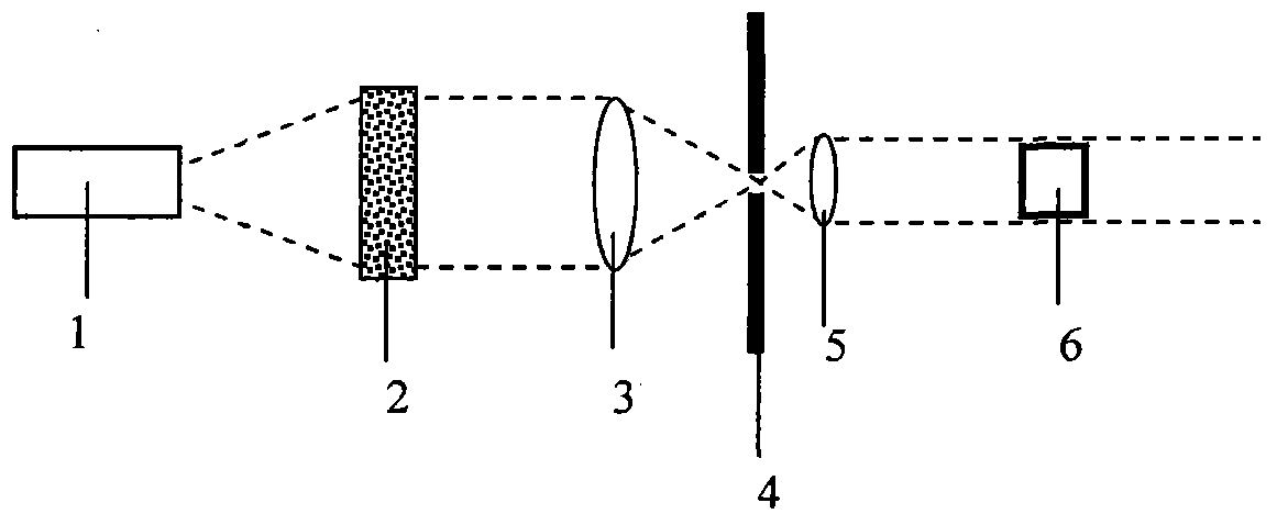
图1是本发明的光学整形部分结构原理图。图中有:入射光源1、散射体2、大透镜3、小孔4、小透镜5、微型干涉仪阵列6。Fig. 1 is a structural principle diagram of the optical shaping part of the present invention. In the figure, there are: incident
图2是本发明的光学整形部分另一结构原理图。图中有:入射光源1、大透镜3、小孔4、小透镜5、微型干涉仪阵列6、光学准直器7。Fig. 2 is another structural principle diagram of the optical shaping part of the present invention. In the figure, there are: incident
图3是本发明的微型干涉仪阵列结构示意图。图中有台阶8、台阶9、基底10、CCD阵列11。其中台阶8、台阶9、基底10均为透明材料,如PMMA。Fig. 3 is a schematic diagram of the micro-interferometer array structure of the present invention. In the figure, there are
图4是图4其中一个微型干涉仪横截图。图中有台阶8、台阶9、基底10、遮挡物12、CCD像素13。其中台阶8高度对于不同的微型干涉仪是相同的,而台阶9对于不同的微型干涉仪是互不相同。CCD像素13的大部分面积被遮挡板12挡住,只留有一个小孔。Fig. 4 is a cross section of one of the micro interferometers in Fig. 4 . In the figure, there are
图5是本发明采用的入射光光谱频率划分方法。横坐标表示频率,单位是赫兹;纵坐标是归一化光谱功率,单位是瓦特每赫兹。用微积分的方法把入射光谱按照频率划分成n等份,每一份取其中心频率,每一份的频宽为Δf。fi是其中任意一个频率,它的幅值为P(fi)。Fig. 5 is the frequency division method of the incident light spectrum adopted in the present invention. The abscissa represents the frequency in Hertz; the ordinate is the normalized spectral power in Watts per Hertz. The incident spectrum is divided into n equal parts according to the frequency by calculus, and the center frequency of each part is taken, and the bandwidth of each part is Δf. f i is any one of the frequencies, and its amplitude is P(f i ).
图6、图7、图8、图9、图10、图11、图12都是采用图3、图4所示的结构以及图5所示的频率划分方法得到的归一化复原光谱和入射光谱的对比图。在这些图中,上横坐标表示波长,单位是纳米;下横坐标表示频率,单位是赫兹;纵坐标是归一化光谱功率,单位是瓦特每赫兹;图中的实线表示入射光谱,图中的虚线表示复原光谱。Figure 6, Figure 7, Figure 8, Figure 9, Figure 10, Figure 11, and Figure 12 are the normalized restored spectra and incident Comparison chart of spectra. In these figures, the upper abscissa represents wavelength in nanometers; the lower abscissa represents frequency in Hertz; the ordinate represents normalized spectral power in Watts per Hertz; the solid line in the figure represents the incident spectrum, Fig. The dotted line in represents the restored spectrum.
图6是采用本发明的红外波段光谱复原图。所用微型干涉仪的数量是5000。其中入射光谱呈正态分布,其数学期望和标准方差分别是275THz和5THz。测量频率从250THz到750THz,测量频宽为500THz。频率分辨率为100GHz,最高波长分辨率为53.33pm。Fig. 6 is a restoration diagram of the infrared band spectrum using the present invention. The number of micro-interferometers used is 5000. The incident spectrum is normally distributed, and its mathematical expectation and standard deviation are 275THz and 5THz, respectively. The measurement frequency is from 250THz to 750THz, and the measurement bandwidth is 500THz. The frequency resolution is 100GHz, and the highest wavelength resolution is 53.33pm.
图7是采用本发明的二次复原技术,在图6基础上的高分辨率光谱复原图。所用微型干涉仪的数量是5000。测量频率从250THz到300THz,测量频宽为50THz。频率分辨率为10GHz,最高波长分辨率为5.33pm。Fig. 7 is a high-resolution spectral restoration diagram based on Fig. 6 using the secondary restoration technique of the present invention. The number of micro-interferometers used is 5000. The measurement frequency is from 250THz to 300THz, and the measurement bandwidth is 50THz. The frequency resolution is 10GHz, and the highest wavelength resolution is 5.33pm.
图8是采用本发明的具有较大失真的光谱复原图。所用微型干涉仪的数量是5000。其中入射光谱呈正态分布,其数学期望和标准方差分别是275THz和50GHz。测量频率从250THz到750THz,测量频宽为500THz。频率分辨率为100GHz,分辨率比入射光谱的标准方差还要大,所以失真明显。但仍然可以显示入射光谱的大概形貌。Fig. 8 is a spectrum restoration diagram with large distortion using the present invention. The number of micro-interferometers used is 5000. The incident spectrum is normally distributed, and its mathematical expectation and standard deviation are 275THz and 50GHz, respectively. The measurement frequency is from 250THz to 750THz, and the measurement bandwidth is 500THz. The frequency resolution is 100GHz, and the resolution is larger than the standard deviation of the incident spectrum, so the distortion is obvious. However, it can still show the approximate shape of the incident spectrum.
图9是采用本发明的紫外波段光谱复原图。所用微型干涉仪的数量是5000。其中入射光谱呈正态分布,其数学期望和标准方差分别是745THz和2THz。测量频率从250THz到750THz,测量频宽为500THz。频率分辨率为100GHz,最高波长分辨率为53.33pm。Fig. 9 is a restoration diagram of the ultraviolet band spectrum using the present invention. The number of micro-interferometers used is 5000. The incident spectrum is normally distributed, and its mathematical expectation and standard deviation are 745THz and 2THz, respectively. The measurement frequency is from 250THz to 750THz, and the measurement bandwidth is 500THz. The frequency resolution is 100GHz, and the highest wavelength resolution is 53.33pm.
图10是采用本发明的二次复原技术,在图9基础上的高分辨率光谱复原图。所用微型干涉仪的数量是5000。测量频率从740THz到750THz,测量频宽为10THz。频率分辨率为2GHz,最高波长分辨率为1.067pm。Fig. 10 is a high-resolution spectral restoration diagram based on Fig. 9 using the secondary restoration technology of the present invention. The number of micro-interferometers used is 5000. The measurement frequency is from 740THz to 750THz, and the measurement bandwidth is 10THz. The frequency resolution is 2GHz, and the highest wavelength resolution is 1.067pm.
图11是采用过少的微型干涉仪所得到的光谱复原图(可见波段)。所用微型干涉仪的数量分别是10、25、50,所得到的复原光谱分别用圆圈加虚线、叉加虚线、正方形圈加虚线表示。其中当微型干涉仪数目为10、25时,失真较大。Fig. 11 is a spectrum recovery diagram (visible waveband) obtained by using too few micro-interferometers. The number of micro-interferometers used is 10, 25, and 50 respectively, and the obtained restored spectra are represented by circles plus dashed lines, crosses plus dashed lines, and square circles plus dashed lines. Among them, when the number of micro interferometers is 10 or 25, the distortion is relatively large.
图12是采用正常和过多的微型干涉仪所得到的光谱复原图(紫外波段)。其中图(a)所用微型干涉仪的数量是5000,失真不明显;图(b)所用微型干涉仪的数量是10000,有较大失真。Fig. 12 is a spectrum recovery diagram (ultraviolet band) obtained by using normal and excessive micro-interferometers. Among them, the number of micro interferometers used in figure (a) is 5000, and the distortion is not obvious; the number of micro interferometers used in figure (b) is 10000, and there is a large distortion.
具体实施方式Detailed ways
首先,对入射光进行光学整形,使得光强均匀的平面光垂直入射到微型干涉仪阵列表面。分两种情况:如果入射光是从远处射过来的束腰较宽的比较弱的光,采用图1所示装置。首先让光通过散射体2后,使得光强分布均匀。然后再使其通过准直装置,即大透镜3、小孔4、小透镜5。通过准直装置后,不仅使得只有平行光才能入射到微型干涉仪阵列6,而且提高了光强分布密度,有利于提高灵敏度。如果入射光是从近处射过来的束腰很窄的比较强的光,采用图2所示装置,首先让光通过准直镜7,使得光能大致平行。然后再依次通过小透镜5、小孔4、大透镜3,使得入射光的光束直径变大。那么把微型干涉仪阵列6放在光束的中间位置,在中间很小的面积上,可以保证光强的大致均匀。First, the incident light is optically shaped so that the plane light with uniform light intensity is perpendicular to the surface of the micro-interferometer array. There are two situations: if the incident light is a relatively weak light with a wider beam waist and a wider beam from a distance, use the device shown in Figure 1. First, light is allowed to pass through the
所用的微型干涉仪阵列6如图3所示,包括一系列由两个不同高度的在基底薄膜10上的台阶组成,台阶8、台阶9、基底10都采用聚甲基丙烯酸甲酯(PMMA)。基底薄膜10的正下方是CCD阵列11,用于测量干涉光强的大小。两个不同高度的台阶,其中一个台阶8在各个微型干涉仪中高度各不相同,高度在0至10个微米范围内线性变化;另一个台阶9的高度在不同的微型干涉仪中始终相同,为5微米。两个台阶的宽度为1.4微米。图4是其中一个微型干涉仪的横截面图,其中基底10的厚度为2微米,CCD面元13大部分面积被遮挡板12遮住,只留有一个小孔,宽度为0.15微米。Used
因此,用CCD11测量各个像素面元上的功率,并对CCD11所得数据进行修正,修正由于暗电流及探测器响应不均匀等原因所引起的测量误差。Therefore, CCD11 is used to measure the power on each pixel panel, and the data obtained by CCD11 is corrected to correct the measurement errors caused by dark current and uneven response of the detector.
然后,按照CCD11的测量频率范围,将其该频段分成n等份。如图5所示,假设每一份的中心频率为f1,f2,…fn,频宽为Δf。如果n的数目比较多,那么根据微积分的原理,入射光的整个功率可以用下式表示:Then, according to the measurement frequency range of CCD11, the frequency band is divided into n equal parts. As shown in FIG. 5 , it is assumed that the center frequency of each portion is f 1 , f 2 , . . . f n , and the bandwidth is Δf. If the number of n is relatively large, then according to the principle of calculus, the entire power of the incident light can be expressed by the following formula:
P0=P(f1)Δf+P(f2)Δf+...+P(fn)Δf,P 0 =P(f 1 )Δf+P(f 2 )Δf+...+P(f n )Δf,
这里P(fi)表示频率为fi的幅度。当入射光经过其中一个微型干涉仪,CCD面元13上所测到的功率应为:Here P(f i ) denotes the magnitude at frequency fi . When the incident light passes through one of the micro-interferometers, the power measured on the
P=C1P(f1)Δf+C2P(f2)Δf+...+CnP(fn)Δf,P=C 1 P(f 1 )Δf+C 2 P(f 2 )Δf+...+C n P(f n )Δf,
这里,C1,C2,…Cn分别为频率为f1,f2…fn经过该微型干涉仪的透射系数。那么入射光照射n个微型干涉仪后,CCD阵列11可以测得到一系列功率,他们的功率可以表示为:Here, C 1 , C 2 , ... C n are the transmission coefficients of frequencies f 1 , f 2 ... f n passing through the micro-interferometer respectively. Then after the incident light irradiates n micro-interferometers, the
P1=C11P(f1)Δf+C12P(f2)Δf+...+C1nP(fn)Δf,P 1 =C 11 P(f 1 )Δf+C 12 P(f 2 )Δf+...+C 1n P(f n )Δf,
P2=C21P(f1)Δf+C22P(f2)Δf+...+C2nP(fn)Δf,P 2 =C 21 P(f 1 )Δf+C 22 P(f 2 )Δf+...+C 2n P(f n )Δf,
Pn=Cn1P(f1)Δf+Cn2P(f2)Δf+...+CnnP(fn)Δf,P n =C n1 P(f 1 )Δf+C n2 P(f 2 )Δf+...+C nn P(f n )Δf,
其中Cij是频率为fj的光通过第i个干涉仪的透射系数。因此,当我们事先测得各个频率通过各个微型干涉仪的透射系数,就可以根据CCD11阵列所测得的功率组成如上所示的线性方程组。如果写成矩阵的形式,假设C为系数矩阵,y为CCD11各面元所测值组成的矩阵,即where C ij is the transmission coefficient of light of frequency f j through the ith interferometer. Therefore, when we have measured the transmission coefficients of each frequency through each micro-interferometer in advance, we can form the linear equations shown above based on the power measured by the CCD11 array. If it is written in the form of a matrix, assume that C is a coefficient matrix, and y is a matrix composed of the measured values of each panel of CCD11, that is

我们可以得到如下用矩阵表示的方程组:We can obtain the following system of equations represented by a matrix:
Cx=yCx=y
这里,here,
因此,入射光的光谱可以通过对P(f1),P(f2),...P(fn)进行拟合而得到,P(f1),P(f2),...P(fn)是如下矩阵的矩阵元素Therefore, the spectrum of the incident light can be obtained by fitting P(f 1 ), P(f 2 ), ... P(f n ), P(f 1 ), P(f 2 ), ... P(f n ) is the matrix element of the following matrix
不过,上述方程组中的增广矩阵的数值不是准确的数值。由于测量误差等原因,上述方程组为病态方程组。因此很难用普通的方法去复原入射光谱。因此,用Tikhonov正则化方法可以更好地求解该线性方程组,并得到以下一系列仿真结果。对这些仿真结果进行定标,就可以得到入射光的光谱。However, the values of the augmented matrix in the above equations are not exact values. Due to measurement errors and other reasons, the above equations are ill-conditioned equations. Therefore, it is difficult to restore the incident spectrum by ordinary methods. Therefore, using the Tikhonov regularization method can better solve the linear equations, and obtain the following series of simulation results. By calibrating these simulation results, the spectrum of the incident light can be obtained.
图6、图7、图8、图9、图10、图11、图12都是采用图3、图4所示的结构以及图5所示的频率划分方法,通过用Tikhonov正则化方法求解线性方程组得到的归一化的复原光谱和入射光谱的对比图。在这些图中,上横坐标表示波长,单位是纳米;下横坐标表示频率,单位是赫兹;纵坐标是归一化光谱功率,单位是瓦特每赫兹;图中的实线表示入射光谱,图中的虚线表示复原光谱。Figure 6, Figure 7, Figure 8, Figure 9, Figure 10, Figure 11, and Figure 12 all use the structure shown in Figure 3 and Figure 4 and the frequency division method shown in Figure 5, by using the Tikhonov regularization method to solve the linear The comparison chart of the normalized restored spectrum and the incident spectrum obtained by the equation set. In these figures, the upper abscissa represents wavelength in nanometers; the lower abscissa represents frequency in Hertz; the ordinate represents normalized spectral power in Watts per Hertz; the solid line in the figure represents the incident spectrum, Fig. The dotted line in represents the restored spectrum.
图6是采用本发明的红外波段光谱复原图。所用微型干涉仪的数量是5000。其中入射光谱呈正态分布,其数学期望和标准方差分别是275THz和5THz。测量频率从250THz到750THz,测量频宽为500THz。频率分辨率为100GHz,最高波长分辨率为53.33pm。Fig. 6 is a restoration diagram of the infrared band spectrum using the present invention. The number of micro-interferometers used is 5000. The incident spectrum is normally distributed, and its mathematical expectation and standard deviation are 275THz and 5THz, respectively. The measurement frequency is from 250THz to 750THz, and the measurement bandwidth is 500THz. The frequency resolution is 100GHz, and the highest wavelength resolution is 53.33pm.
图6的分辨率如果还够高,可以采用本发明的二次复原技术,如图7所示。图7是在图6基础上的高分辨率光谱复原图。它采用了第一种方法:即从第一次复原,知道入射光谱的全部频率落在250THz到300THz之间。那么在第二次光谱复原时,由于所用微型干涉仪的数量还是5000,但测量频率变成了从250THz到300THz,测量频宽变为50THz。如果事先测得各个频率(即在250THz到300THz范围内的5000个频率)在各个微型干涉仪和准直系统的透射系数,那么就可以得到图7所示的高分辨率光谱复原图,它的频率分辨率为10GHz,最高波长分辨率为5.33pm。If the resolution in FIG. 6 is high enough, the secondary restoration technology of the present invention can be used, as shown in FIG. 7 . Fig. 7 is a high-resolution spectral restoration diagram based on Fig. 6 . It uses the first method: that is, from the first restoration, knowing that all frequencies of the incident spectrum fall between 250THz and 300THz. Then, in the second spectrum recovery, since the number of micro interferometers used is still 5000, but the measurement frequency is changed from 250THz to 300THz, and the measurement bandwidth is changed to 50THz. If the transmission coefficients of each frequency (that is, 5000 frequencies in the range of 250THz to 300THz) in each micro-interferometer and collimation system are measured in advance, then the high-resolution spectral restoration diagram shown in Figure 7 can be obtained, its The frequency resolution is 10GHz, and the highest wavelength resolution is 5.33pm.
图8是采用本发明的具有较大失真的光谱复原图。所用微型干涉仪的数量是5000。其中入射光谱呈正态分布,其数学期望和标准方差分别是275THz和50GHz。测量频率从250THz到750THz,测量频宽为500THz。频率分辨率为100GHz,分辨率比入射光谱的标准方差还要大,所以失真明显。但仍然可以显示入射光谱的大概形貌。Fig. 8 is a spectrum restoration diagram with large distortion using the present invention. The number of micro-interferometers used is 5000. The incident spectrum is normally distributed, and its mathematical expectation and standard deviation are 275THz and 50GHz, respectively. The measurement frequency is from 250THz to 750THz, and the measurement bandwidth is 500THz. The frequency resolution is 100GHz, and the resolution is larger than the standard deviation of the incident spectrum, so the distortion is obvious. However, it can still show the approximate shape of the incident spectrum.
图9是采用本发明的紫外波段光谱复原图。所用微型干涉仪的数量是5000。其中入射光谱呈正态分布,其数学期望和标准方差分别是745THz和2THz。测量频率从250THz到750THz,测量频宽为500THz。频率分辨率为100GHz,最高波长分辨率为53.33pm。Fig. 9 is a restoration diagram of the ultraviolet band spectrum using the present invention. The number of micro-interferometers used is 5000. The incident spectrum is normally distributed, and its mathematical expectation and standard deviation are 745THz and 2THz, respectively. The measurement frequency is from 250THz to 750THz, and the measurement bandwidth is 500THz. The frequency resolution is 100GHz, and the highest wavelength resolution is 53.33pm.
图9的分辨率如果还够高,可以采用本发明的二次复原技术,如图10所示。图10是在图9基础上的高分辨率光谱复原图。它采用了第二种方法:即从第一次复原,知道入射光谱的主要频率落在740THz到750THz之间。那么在第二次光谱复原时,加入滤波镜,滤掉不在740THz到750THz范围的所有入射光。由于所用微型干涉仪的数量还是5000,但测量频率变成了从740THz到750THz,测量频宽变为10THz。如果事先测得各个频率(即在740THz到750THz内的5000个频率)通过各个微型干涉仪和准直、滤波系统的透射系数,那么就可以得到图10所示的高分辨率光谱复原图,它的频率分辨率为2GHz,最高波长分辨率为1.067pm。If the resolution in FIG. 9 is high enough, the secondary restoration technology of the present invention can be used, as shown in FIG. 10 . Fig. 10 is a high-resolution spectral restoration diagram based on Fig. 9 . It uses the second method: that is, from the first recovery, knowing that the main frequency of the incident spectrum falls between 740THz and 750THz. Then, in the second spectral restoration, a filter is added to filter out all incident light not in the range of 740THz to 750THz. Since the number of micro interferometers used is still 5000, the measurement frequency has changed from 740THz to 750THz, and the measurement bandwidth has changed to 10THz. If the transmission coefficients of each frequency (that is, 5000 frequencies within 740THz to 750THz) passing through each micro-interferometer, collimation, and filtering system are measured in advance, then the high-resolution spectral restoration map shown in Figure 10 can be obtained. The frequency resolution is 2GHz, and the highest wavelength resolution is 1.067pm.
微型干涉仪的数量过多或过少都会引起复原光谱的失真。Too many or too few micro-interferometers will cause distortion of the restored spectrum.
图11是采用过少的微型干涉仪所得到的光谱复原图(可见波段)。所用微型干涉仪的数量分别是10、25、50,所得到的复原光谱分别用圆圈加虚线、叉加虚线、正方形圈加虚线表示。其中当微型干涉仪数目为10、25时,失真较大;而当微型干涉仪数目为50时,没有明显失真。Fig. 11 is a spectrum recovery diagram (visible waveband) obtained by using too few micro-interferometers. The number of micro-interferometers used is 10, 25, and 50 respectively, and the obtained restored spectra are represented by circles plus dashed lines, crosses plus dashed lines, and square circles plus dashed lines. Among them, when the number of micro-interferometers is 10 or 25, the distortion is relatively large; and when the number of micro-interferometers is 50, there is no obvious distortion.
图12是采用正常和过多的微型干涉仪所得到的光谱复原图(紫外波段)。其中Fig. 12 is a spectrum recovery diagram (ultraviolet band) obtained by using normal and excessive micro-interferometers. in
图(a)所用微型干涉仪的数量是5000,失真不明显;图(b)所用微型干涉仪的数量是10000,有较大失真。The number of micro interferometers used in picture (a) is 5000, and the distortion is not obvious; the number of micro interferometers used in picture (b) is 10000, and there is a large distortion.
Claims (3)
Priority Applications (1)
| Application Number | Priority Date | Filing Date | Title |
|---|---|---|---|
| CN2009102642539A CN101881663B (en) | 2009-12-29 | 2009-12-29 | Spectrum recovering method of micro spectrograph with phase modulating array |
Applications Claiming Priority (1)
| Application Number | Priority Date | Filing Date | Title |
|---|---|---|---|
| CN2009102642539A CN101881663B (en) | 2009-12-29 | 2009-12-29 | Spectrum recovering method of micro spectrograph with phase modulating array |
Publications (2)
| Publication Number | Publication Date |
|---|---|
| CN101881663A CN101881663A (en) | 2010-11-10 |
| CN101881663B true CN101881663B (en) | 2011-08-03 |
Family
ID=43053733
Family Applications (1)
| Application Number | Title | Priority Date | Filing Date |
|---|---|---|---|
| CN2009102642539A Expired - Fee Related CN101881663B (en) | 2009-12-29 | 2009-12-29 | Spectrum recovering method of micro spectrograph with phase modulating array |
Country Status (1)
| Country | Link |
|---|---|
| CN (1) | CN101881663B (en) |
Families Citing this family (4)
| Publication number | Priority date | Publication date | Assignee | Title |
|---|---|---|---|---|
| CN102608061B (en) * | 2012-03-21 | 2014-03-12 | 西安交通大学 | Improved method for extracting Fourier transformation infrared spectrum characteristic variable of multi-component gas by aid of TR (Tikhonov regularization) |
| CN103743483B (en) * | 2013-10-28 | 2015-11-11 | 中国工程物理研究院流体物理研究所 | Difference spectrum formation method |
| CN103777376B (en) * | 2014-01-17 | 2016-05-25 | 太原理工大学 | The multiple far field beam focal spot shapes of expection or position method for independently controlling based on optical phased array |
| CN103760689B (en) * | 2014-01-17 | 2016-05-25 | 太原理工大学 | Far field beam focal spot position control method is organized in expection based on optical phased array more |
Citations (1)
| Publication number | Priority date | Publication date | Assignee | Title |
|---|---|---|---|---|
| CN101091100A (en) * | 2004-11-18 | 2007-12-19 | 摩根研究股份有限公司 | Miniature fourier transform spectrophotometer |
-
2009
- 2009-12-29 CN CN2009102642539A patent/CN101881663B/en not_active Expired - Fee Related
Patent Citations (1)
| Publication number | Priority date | Publication date | Assignee | Title |
|---|---|---|---|---|
| CN101091100A (en) * | 2004-11-18 | 2007-12-19 | 摩根研究股份有限公司 | Miniature fourier transform spectrophotometer |
Non-Patent Citations (1)
| Title |
|---|
| JP特开平5-190959A 1993.07.30 |
Also Published As
| Publication number | Publication date |
|---|---|
| CN101881663A (en) | 2010-11-10 |
Similar Documents
| Publication | Publication Date | Title |
|---|---|---|
| US11415460B2 (en) | Fabry-Perot Fourier transform spectrometer | |
| JP4707653B2 (en) | Method and system for static multimode multiplex spectroscopy | |
| CN105675131B (en) | THz wave spectrometry device and its measuring method based on diffraction effect | |
| CN102564586B (en) | Miniature spectrograph with diffraction hole array structure and high resolution spectrum reconstruction method thereof | |
| WO2021117632A1 (en) | Quantum absorption spectroscopy system and quantum absorption spectroscopy method | |
| CN103063304B (en) | Image plane interference Hyper spectral Imaging device and method is sheared in dispersion | |
| WO2020035003A1 (en) | Spectrometer and spectrum detection analysis method using same | |
| JP6513697B2 (en) | Optical interference device | |
| CN103424190B (en) | Double wedge plate dispersion shear interference Hyper spectral Imaging device and method | |
| JP2009265101A (en) | Method, phase grating and device for analyzing wave surface of light beam | |
| JP4862051B2 (en) | Three-wave transverse shear compact achromatic optical interferometer | |
| CN101881663B (en) | Spectrum recovering method of micro spectrograph with phase modulating array | |
| CN105511066A (en) | Microscopic polarization imaging device based on microwave sheet array and implement method thereof | |
| US20200300699A1 (en) | Method and apparatus for linear variable bandpass filter array optical spectrometer | |
| Park et al. | Miniaturization of optical spectroscopes into Fresnel microspectrometers | |
| CN115712162B (en) | Superlens-grating structure and design method thereof | |
| CN110044482B (en) | Spectrum testing method based on reflection type random diffraction sheet | |
| CN117664527A (en) | Computational spectrum reconstruction system for single-frequency narrow linewidth laser linewidth detection | |
| CN115979422A (en) | A device and method for defect scattering computational reconstruction spectrum detection | |
| EP3978965A1 (en) | Diffraction element and imaging device | |
| CN210293456U (en) | Spectral measurement device based on reflective random diffraction piece | |
| CN106092321B (en) | A kind of measuring method of the THz wave frequency measuring equipment based on CARS effects | |
| CN209280141U (en) | A kind of gradation type diffusing structure spectral analysis device | |
| CN114674745A (en) | Spectral reconstruction method and spectrometer | |
| CN114739513A (en) | Polarization spectrum measuring device |
Legal Events
| Date | Code | Title | Description |
|---|---|---|---|
| C06 | Publication | ||
| PB01 | Publication | ||
| C10 | Entry into substantive examination | ||
| SE01 | Entry into force of request for substantive examination | ||
| C14 | Grant of patent or utility model | ||
| GR01 | Patent grant | ||
| ASS | Succession or assignment of patent right |
Owner name: NANJING FANGYUAN GLOBAL PHOTOELECTRIC MATERIAL CO. Free format text: FORMER OWNER: NANJING POST + TELECOMMUNICATION UNIV. Effective date: 20141126 Free format text: FORMER OWNER: THE CHINESE UNIVERSITY OF HONG KONG, CHINA Effective date: 20141126 |
|
| C41 | Transfer of patent application or patent right or utility model | ||
| COR | Change of bibliographic data |
Free format text: CORRECT: ADDRESS; FROM: 210003 NANJING, JIANGSU PROVINCE TO: 210000 NANJING, JIANGSU PROVINCE |
|
| TR01 | Transfer of patent right |
Effective date of registration: 20141126 Address after: 210000 Jiangsu city of Nanjing province Nanjing economic and Technological Development Zone Heng Road No. 8 Room 511 branch base Patentee after: Nanjing Fangyuan Huanqiu photoelectric material Co., Ltd. Address before: 210003 Nanjing City, Jiangsu Province, the new model road No. 66 Patentee before: Nanjing Post & Telecommunication Univ. Patentee before: Chinese University Hong Kong |
|
| ASS | Succession or assignment of patent right |
Owner name: NANJING FANGYUAN GLOBAL DISPLAY TECHNOLOGY CO., LT Free format text: FORMER OWNER: NANJING FANGYUAN GLOBAL PHOTOELECTRIC MATERIAL CO., LTD. Effective date: 20150511 |
|
| C41 | Transfer of patent application or patent right or utility model | ||
| COR | Change of bibliographic data |
Free format text: CORRECT: ADDRESS; FROM: 210000 NANJING, JIANGSU PROVINCE TO: 210003 NANJING, JIANGSU PROVINCE |
|
| TR01 | Transfer of patent right |
Effective date of registration: 20150511 Address after: 210003 Nanjing, Gulou District, Jiangsu, No. 38 Guangdong Road Patentee after: Nanjing Fangyuan Global Display Technology Co., Ltd. Address before: 210000 Jiangsu city of Nanjing province Nanjing economic and Technological Development Zone Heng Road No. 8 Room 511 branch base Patentee before: Nanjing Fangyuan Huanqiu photoelectric material Co., Ltd. |
|
| CF01 | Termination of patent right due to non-payment of annual fee |
Granted publication date: 20110803 Termination date: 20151229 |
|
| EXPY | Termination of patent right or utility model |