CN101856013B - Motor control device for electric fishing reel - Google Patents
Motor control device for electric fishing reel Download PDFInfo
- Publication number
- CN101856013B CN101856013B CN201010145563.1A CN201010145563A CN101856013B CN 101856013 B CN101856013 B CN 101856013B CN 201010145563 A CN201010145563 A CN 201010145563A CN 101856013 B CN101856013 B CN 101856013B
- Authority
- CN
- China
- Prior art keywords
- fishing line
- line length
- motor
- fishing
- setting
- Prior art date
- Legal status (The legal status is an assumption and is not a legal conclusion. Google has not performed a legal analysis and makes no representation as to the accuracy of the status listed.)
- Active
Links
Images


Classifications
-
- A—HUMAN NECESSITIES
- A01—AGRICULTURE; FORESTRY; ANIMAL HUSBANDRY; HUNTING; TRAPPING; FISHING
- A01K—ANIMAL HUSBANDRY; CARE OF BIRDS, FISHES, INSECTS; FISHING; REARING OR BREEDING ANIMALS, NOT OTHERWISE PROVIDED FOR; NEW BREEDS OF ANIMALS
- A01K89/00—Reels
- A01K89/015—Reels with a rotary drum, i.e. with a rotating spool
- A01K89/017—Reels with a rotary drum, i.e. with a rotating spool motor-driven
- A01K89/0171—Spring motors
- A01K89/0172—Spring motors actuated in response to pull on line
Landscapes
- Life Sciences & Earth Sciences (AREA)
- Environmental Sciences (AREA)
- Animal Husbandry (AREA)
- Biodiversity & Conservation Biology (AREA)
Abstract
The present invention provides a motor control device for an electric fishing reel, which is not related with the magnitude that functions to the fishing line and can accurately place a fishing tackle combination on a shipboard. A fishing reel control part (30) controls a motor (12) which drives a winding reel (10) and winds the fishing line. An output structure of a winding reel sensor (41) measures the length of the fishing line released from the winding reel (10). The magnitude of load which functions to the fishing line is detected through detecting the value of the current that flows through the motor (12). The shipboard stop position FN is set according to the load detection result. When the fishing line is retreated, the shipboard stop position FN is used for stopping the rotation of the motor (12). When the length of the measured fishing line obtains the preset shipboard stop position FN, the motor (12) stops rotation.
Description
Technical field
The present invention relates to a kind of motor control assembly, relate in particular to a kind of motor control assembly of electric fishing reel, in electric fishing reel, spool be used for reeling fishing line being driven by motor, this control device is for controlling the motor of this driving spool.
Background technology
In electric fishing reel, make spool furl direction to fishing line with motor and rotate.In the electric fishing reel of prior art, people are improved or are reduced the rotating speed of motor by console switch, adjust the speed that furls of spool.In the time that the speed that furls of spool has been set, its current value meeting controlled device control, now, irrelevant with payload, spool can maintain certain speed that furls.
In above-mentioned electric fishing reel, people are known to ship side stop mode, and under stop mode, in the time angling group to arrive ship side, its motor will stop operating on the quarter.If there has been this above-mentioned ship side stop mode, in the time fish having been angled or changed bait, because the group of angling of collecting can be in ship side position, angles group or fish so be easy to regain, thereby can again jettisoning rapidly.
In the electric fishing reel motor control assembly with ship side stop mode, this motor control assembly that people are known to can will angle group to furl fishing rod pole head (for example, with reference to patent documentation 1).The motor control assembly of the prior art can detect rotation direction and the rotating speed of spool, then by rotation direction and the rotating speed instrumentation fishing line length of the spool detecting.When instrumentation to fishing line length regained and arrived when ship side position, this motor control assembly can reduce to flow through drive current of motor, then, when detecting that while thinking that fishing line has been furled the rated condition of fishing rod pole head, this motor control assembly can make motor stop operating.
No. 2004-73089, [patent documentation 1] Japanese patent of invention Publication JP
When by the rotation direction of spool and rotating speed instrumentation fishing line length, because effect is to the difference of the payload of fishing line, there will be actual fishing line length and instrumentation to fishing line length between have the problem of difference.For example have compared with large fish and sting and angle group to wait and when fishing line is produced to larger load (tension force), will be according to furling and angle group than the little winding diameter of winding diameter of storage.Therefore the fishing line length not furled showing is larger than the fishing line length in fact not furled.
In addition, withdrawal angle group or take floating while the method that makes the fishhook that angles group move about under cursory without plummet such as angling to fish etc., because of effect less to the load of fishing line, so will be according to furling and angle group than the large winding diameter of winding diameter of storage.Therefore the fishing line length not furled showing is less than the fishing line length in fact not furled.
Therefore, in above-mentioned motor control assembly of the prior art, do angling such as withdrawal for the situations such as group of used time for almost not loading, although in fact angle group to furl on ship side position, this motor control assembly is still likely judged as angles group not furled on ship side position.The result of this judgement is, the deceleration of spool or stop action and there will be hysteresis, thus likely there is the situation of angling group and the guide portion of fishing rod pole head to scratch.If angle group and the guide portion of fishing rod pole head to scratch, likely can produce the problem that scratches guide portion or angle group dislocation.And under the larger state of load, furl while angling group, when this angle group from after stopping on the quarter till actual taking in hand needs drive motors again therebetween, or need manually be furled and put in place.
Summary of the invention
In view of the above problems, the object of this invention is to provide a kind of motor control assembly of electric fishing reel, irrelevant to the payload of fishing line with effect, can will angle group to be placed in exactly ship side position.
For achieving the above object, a technical scheme of the present invention is:
A motor control assembly for electric fishing reel, in this electric fishing reel, spool is driven by motor, and for the fishing line of reeling, motor control assembly is used for controlling this motor, and motor control assembly comprises:
Fishing line length instrumentation mechanism, the length of the fishing line of emitting from described spool by its instrumentation;
Load detector structure, the size of the load by its detection effect on described fishing line;
Fishing line length setting mechanism when motor stops operating, according to the testing result of described load detector structure, fishing line length setting mechanism when this motor stops operating sets, the fishing line length while making motor stop operating in the time furling fishing line;
Motor control mechanism, when described fishing line length instrumentation mechanism instrumentation to the fishing line length of fishing line length when reaching the described motor of having set and stopping operating time, by this motor control mechanism, described motor is stopped operating,
Described in carrying out, furl fishing line action, when the load detecting by described load detector structure is less than setting, compared with while being greater than described setting with described load, fishing line length setting when fishing line length setting mechanism when described motor stops operating stops operating described motor must be longer
Motor control assembly also comprises turning feeler mechanism, detect rotation direction and the rotating speed of described spool by it, according to the testing result of described turning feeler mechanism, in the time furling fishing line action described in carrying out, start to turn to through after the stipulated time from motor, until fishing line length is while reaching than long the 2nd fishing line length of predefined the 1st fishing line length, fishing line length setting mechanism while being stopped operating by described motor contrasts the load mean value and the described setting that are detected by described load detector structure, in the time that described load mean value is less than described setting, fishing line length setting mechanism when described motor stops operating is the fishing line length of motor while stopping operating by the 3rd fishing line length setting, described in the 3rd fishing line Length Ratio, the 1st fishing line length is long but shorter than the 2nd fishing line length.
In addition, to achieve these goals, the present invention also adopts following technical scheme:
Technical scheme 1: a kind of motor control assembly of electric fishing reel, in the time furling fishing line, drives the motor of fishing line reel to control by it to being used for.It comprises fishing line length instrumentation mechanism, load detector structure, motor stop operating fishing line length setting mechanism and motor control mechanism.Wherein, fishing line length instrumentation mechanism is used for the length of the fishing line that instrumentation emits from spool.Load detector structure is used for the load of detection effect on fishing line.According to the testing result of load detector structure, the fishing line length that stops operating of the motor when fishing line length setting mechanism while being stopped operating by motor is set in and while furling fishing line, motor is stopped operating.When fishing line length instrumentation mechanism instrumentation to the fishing line length of fishing line length when reaching the motor of having set and stopping operating time, motor control mechanism can make motor stop operating.
In above-mentioned motor control assembly, while making spool furl direction and rotate and furl fishing line to fishing line by motor, effect is detected by load detector structure to the load of fishing line, and for example its current value according to the motor of flowing through detects this load.The setting value of the fishing line length when fishing line length setting mechanism while then being stopped operating by motor stops operating according to the size setting motor of load, if load hour, the fishing line length of the numeric ratio reality arriving due to fishing line length instrumentation mechanism instrumentation is short, so in order to angle group to be placed in ship side position, the motor fishing line length setting mechanism that stops operating can set this setting value to such an extent that than load, the fishing line length that stops operating of the motor when larger is long.So, in the time furling fishing line, when instrumentation to fishing line length when reaching motor and stopping operating fishing line length motor stop operating, thereby stop furling the action of fishing line.Now, owing to setting the motor fishing line length that stops operating to the payload of fishing line according to effect, so can suitably set according to the size of load the motor fishing line length that stops operating.Therefore, irrelevant to the size of the load of fishing line with effect, the present invention can will angle group to be placed in exactly on ship side.
Technical scheme 2: on the basis of technical solution of the present invention 1, in the motor control assembly of described electric fishing reel, in the time furling fishing line, when the load being detected by load detector structure is less than setting, fishing line length when motor when fishing line length setting when fishing line length setting mechanism when motor stops operating can stop operating motor must be greater than setting than load stops operating is long.
Now, compared with situation while being less than setting with load, motor when fishing line length setting when fishing line length setting mechanism while stopping operating due to motor can stop operating motor must be greater than setting than the load fishing line length that stops operating is long, so irrelevant to the payload of fishing line with effect, the present invention can will angle group to be placed in more accurately on ship side.In addition, the present invention can also prevent from angling group and the situation that the guide portion of fishing rod pole head scratches to occur.
Technical scheme 3: on the basis of technical solution of the present invention 2, in the motor control assembly of electric fishing reel, also comprise turning feeler mechanism, it is used for detecting rotation direction and the rotating speed of spool, according to the testing result of turning feeler mechanism, in the time furling fishing line, start to turn to through after the stipulated time from motor, until fishing line length is while reaching than long the 2nd fishing line length of predefined the 1st fishing line length, fishing line length setting mechanism while being stopped operating by motor contrasts load mean value and its setting of being detected by load detector structure, in the time that load mean value is less than its setting, fishing line length setting mechanism when motor stops operating can be the motor fishing line length that stops operating by the 3rd fishing line length setting, the 3rd fishing line length has regulation, it is longer but shorter than the 2nd fishing line length than the 1st fishing line length.
Now, because contrasting, the load mean value to changing and its setting set the motor fishing line length that stops operating, so the present invention can will angle group to be further placed in exactly on ship side.Especially as be the standard electromotor fishing line length that stops operating by the 1st fishing line length setting, when load hour, because ship side stop position can become longer than the standard electromotor fishing line length that stops operating, so be easy to angle group to be placed on ship side.In addition, can also prevent from angling group and the situation that the guide portion of fishing rod pole head scratches to occur.
Technical scheme 4: on the basis of technical solution of the present invention 3, in the motor control assembly of electric fishing reel, when load mean value is while being greater than its setting, fishing line length setting mechanism when motor stops operating can be the fishing line length of motor while stopping operating by the short fishing line length setting of predefined ratio the 1st fishing line length.
Now, load exceedes setting, there is prey to sting and angle while group, difference between fishing line length and the actual fishing line length arriving due to instrumentation is less, so the present invention can use the predefined motor fishing line length that stops operating, will angle group to be easily placed on its most suitable position according to the situation of fishing boat.
Technical scheme 5: on the basis of technical solution of the present invention 3 or 4, in the motor control assembly of electric fishing reel, in the time switching on to motor control mechanism, fishing line length setting mechanism when motor stops operating can be the fishing line length of motor while stopping operating by the 1st fishing line length setting.
In the time starting to fish, the present invention can will angle group to be placed on standard ship side stop position like this.
Technical scheme 6: on the basis of technical solution of the present invention 3~5 any one, in the motor control assembly of electric fishing reel, when fishing line Length Ratio the 1st fishing line length that the instrumentation of fishing line length instrumentation mechanism arrives short, and turning feeler mechanism judges that the rotation of spool has stopped the stipulated time when above, fishing line length setting mechanism when motor stops operating can be the fishing line length of motor while stopping operating by fishing line length setting now.
At this moment, owing to the ship side stop position changing because of differences such as fishing boat sizes being set as to the position that in fact rodman makes motor stop operating, so the present invention can set most suitable ship side stop position all the time.
Technical scheme 7: on the basis of technical solution of the present invention 5 or 6, in the motor control assembly of described electric fishing reel, after when reaching the 3rd fishing line length, motor stops operating, furl the fishing line being released by motor, and when load mean value exceedes its setting, fishing line length setting when fishing line length setting mechanism when motor stops operating can stop operating next motor is the 1st fishing line length.
Now, fishing line length setting in the time that motor is stopped operating is that the 3rd fishing line length of growing furls in the process of fishing line afterwards again, in the time having fish to sting to angle group etc. and the load mean value producing while exceeding its setting, fishing line length setting mechanism while stopping operating due to motor can be the fishing line length of motor while stopping operating by the 1st fishing line length setting shorter than the 3rd fishing line length, so the present invention can easily will angle group to be placed on ship side and take off the fish stinging angling in group.
Technical scheme 8: on the basis of technical solution of the present invention 3~7 any one, in the motor control assembly of electric fishing reel, also comprise that decelerating through motor rotates fishing line length setting mechanism, in the time furling fishing line, according to the testing result of load detector structure and turning feeler mechanism, the fishing line length when fishing line length setting mechanism while rotation by above-mentioned decelerating through motor sets the decelerating through motor rotation that makes decelerating through motor rotation.Fishing line length while rotation according to this decelerating through motor, slows down the rotation of motor by motor control mechanism.
Now, because motor occur the slowing down setting of deceleration starting position of rotating is not only with to furl speed relevant, also considered the size of load simultaneously, so, for example, in the time that underload furls fishing line at a high speed, in order not make to angle group to jump out from the water surface etc., be set the situation in advance motor being slowed down, and in the time that high load capacity low speed furls fishing line, be set the situation of motor being slowed down for delaying, therefore, can make motor be easy to be parked in more accurately on the stop position setting, irrelevant to the payload of motor or the rotating speed of motor with effect, in the time furling fishing line, the present invention can will angle group to be placed on the position such as the regulation of ship side etc.
[invention effect]
Adopt time of the present invention, owing to setting the motor fishing line length that stops operating to the payload of fishing line according to effect, and can suitably set the motor fishing line length that stops operating according to the size of load, so, irrelevant to the payload of fishing line with effect, and can will angle group to be placed in ship side position.
Brief description of the drawings
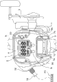
Fig. 1 is the vertical view of the electric fishing reel that adopts in an embodiment of the invention.
Fig. 2 is the vertical view around of display part of the electric fishing reel in Fig. 1.
Fig. 3 is the control block diagram of the electric fishing reel in Fig. 1.
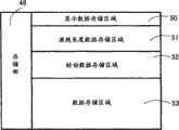
Fig. 4 is the schematic diagram that represents the storage content of storage part.
Fig. 5 is the flow chart of the main program of the electric fishing reel in presentation graphs 1.
Fig. 6 is the flow chart that represents switch input processing flow process.
Fig. 7 is the flow chart that represents each pattern handling process.
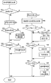
Fig. 8 is the flow chart that represents ship side stop position setting handling process.
[description of reference numerals]
10, spool; 12, motor; 30, fishing line reel control part; 41, spool sensor (example of turning feeler mechanism); 43, current value test section (example of load detector structure); 46, storage part; 53, data storage area
Embodiment
As shown in Figure 1, the electric fishing reel in an embodiment of the invention mainly comprises: reel 1, and it is arranged on fishing rod R; Handle 2, the sidepiece that it is arranged on reel 1, is used for rotating spool; The star-like force mechanisms 3 that unloads, the side that it is arranged on the close reel 1 of handle 2, is used for adjusting brake force.
Reel 1 comprises: framework 7, and its multiple attaching parts 8 by pair of right and left side plate 7a, 7b and connection pair of side plates 7a, 7b form; Left- right side cover 9a, 9b, it is used for distinguishing the left and right sides of cover framework 7.Have the turning cylinder of handle 2 at the side cover 9b upper support of handle 2 place one sides (right side in Fig. 1), this turning cylinder can rotate.On the side cover 9a of the contrary side of handle 2 (left side in Fig. 1), terminal 19 is set, it is used for connecting with the power line 18 that is connected the external power source PS such as battery.
The spool 10 of connecting handle 2 is bearing in the inside of reel 1, and spool 10 can rotate.Be provided with motor 12 in the inside of spool 10, its mode with direct drive makes spool 10 rotate along furling fishing line direction.In addition, on the side surface of handle 2 place one sides of reel 1, be provided with clutch lever 11 and conversion rod 13.The object that clutch lever 11 is set is, by the operation to it, makes the power transfer path between handle 2 and spool 10 and motor 12 and spool 10 carry out combination or separate.In the time emitting fishing line because of the deadweight of angling group, in the time making power transfer path in bonding state, can make unwrapping wire action stop.Not only can make electric machine rotation or stop operating by conversion rod 13, also can determine that motor 12 becomes maximum (top) speed rotary state from the state of stopping operating by its residing swing position.For example, can make motor 12 be adjusted to rotary state from the state of stopping operating by conversion rod 13, and rotary state is divided into 30 grades.For example, on conversion rod 13, there is rotary encoder, can differentiate it from its pendulum angle and rotate progression.
Be fixed with meter housing 4 on the top of reel 1.Meter housing 4 is arranged on the top of reel 1, is formed with display window 20 on its upper surface.As shown in Figure 2, on the upper surface of meter housing 4, there is the display part 5 facing to rodman, it is made up of liquid crystal display, and this liquid crystal display shows the depth of water of angling group or the fish layer position of two different benchmark by display window 20, this benchmark is divided into two kinds of situations from water column or from the meter of the bottom.Around display part 5, be provided with switching manipulation portion 6.Be provided with the fishing line reel control part 30 for controlling motor 12 and display part 5 in the inside of meter housing 4.
Switching manipulation portion 6 comprises: menu switch MN, definite switch ZD that makes zero, and their the first from left right sides are arranged side by side the downside of the display part 5 in Fig. 2; Record switch MM, it is arranged on the right side of display part 5.Often, by a menu switch MN, all can dodge and go out by the order of bottom unwrapping wire.Determine when switch ZD when pressing to make zero, can make to dodge the display section of going out and light or extinguish.The selected pattern by actions menu switch MN, determine that switch ZD makes its operation or stops by making zero.In addition, for example, press and make zero while determining switch ZD when long-time (more than 3 seconds), can angle the deal with return to zero of the group depth of water, thereby the angling group depth of water on display part 5 is reset to zero.In the time carrying out deal with return to zero, rodman will make to angle group concordant with the water surface.When the fish layer position that the shoal of fish need to be assembled or the seabed depth of water are stored in aftermentioned while showing in data storage areas 50, will use and record switch MM.
Fishing line reel control part 30 comprises the microcomputer being arranged in meter housing 4, and this microcomputer comprises CPU, RAM, ROM and I/O interface etc.According to control program, carried out the various control actions such as demonstration control or drive and control of electric machine of display part 5 by fishing line reel control part 30.As shown in Figure 3, on fishing line reel control part 30, connecting various switches, spool sensor (example of turning feeler mechanism) 41, spool counter 42 and the current value test section (example of load detector structure) 43 of conversion rod 13, switching manipulation portion 6.In addition, on fishing line reel control part 30, also connecting buzzer 44, PWM driving loop, display part 5, storage part 46 and other input and output portions.
Under invariablenes turning speed pattern, in rotation data storage area 52, store the maximum duty cycle corresponding with each progression and minimum duty cycle data.Or under constant tension pattern, storage lowest high-current value and the minimum current value corresponding with each progression in rotation data storage area 52.In the present embodiment, for example, when progression SC is during from 1 grade to 4 grades, the invariablenes turning speed pattern of accelerating gradually with the rotating speed of spool 10 is controlled, and progression SC is during from 5 grades to 30 grades, controls to act on the constant tension pattern slowly increasing to the tension force of fishing line.
In data storage areas 53, storage is about various data of fishing line length.For example, wherein store the 1st fishing line length L 1 (such as 6m), the 2nd fishing line length L 2 (such as 21m), the 3rd fishing line length L 3 (such as 10m), for setting ship side stop position FN and being used for setting the rotating speed coefficient data VA, the load coefficient data TB etc. that are parked in the decelerating through motor turned position RX before ship side.
Next according to Fig. 5 and subsequent control flow chart, the concrete control handling process of being undertaken by fishing line reel control part 30 is described.
When electric fishing reel is in the time that power line 18 is connected with external power source PS, can in the step S1 in Fig. 5, carry out initial setting.In this initial setting, by the count value zero clearing of spool timer 42, or reset various variablees or mark.In addition, the position that the ship side stop position FN on fishing line (depth of water example while stopping) can be set in to the 1st fishing line length L 1 (for example 6m), the position of the 1st fishing line length L 1 (for example 6m) is standard ship side stop position.
Next in step S2, carry out Graphics Processing.In Graphics Processing step, can carry out the various Graphics Processings such as depth of water demonstration.Now, can in the 5c of progression viewing area, show progression SC.
In step S3, judge that whether the depth of water LX calculating with the each pattern of aftermentioned is shorter than the 1st fishing line length L 1.Certain switch that judges whether switching manipulation portion 6 in step S4 is pressed and has carried out switch input.In step S5, judge whether spool 10 rotates.This will be according to the output judgement of spool sensor 41.In step S6, judgement has or not other instructions or input etc.
In the time that depth of water LX is less than the 1st fishing line length L 1, can enter step S7 by step S3, in step S7, judge whether to have stopped more than 5 seconds in the time of this depth of water.When the depth of water below 6m, stop more than 5 seconds situations, be to take off fish on the quarter mostly, or carrying out to angling group again to go up the operations such as bait.Therefore, while having stopped more than 5 seconds if be judged as, enter step S8, set the ship side stop position FN on fishing line by depth of water LX now.In the time of dwell time less than 5 seconds, enter step S4 by step S7.
In the time having carried out switch input operation, enter step S9 and carry out switch input processing by step S4.In addition, when detecting that spool 10 has the time of rotation to enter step S10 by step S5.In step S10, carry out each pattern processing.In the time having carried out other instructions or input, enter step S11 and carry out other processing by step S6.
In the switch input processing of step S9, judge whether to have operated conversion rod 13 in the step S15 of Fig. 6.In step S16, judge whether to have pressed and record switch MM.In step S17 judgement, other switches whether are operated.Here said other switches that operated, comprise actions menu switch MN, make zero and determine switch ZD etc.
There is the time of swing to enter step S18 by step S15 by operation if be judged as conversion rod 13.In step S18, judge whether conversion rod 13 is manipulated into progression SC=0.In step S19, judge one of them whether conversion rod 13 is manipulated in progression SC=1~4.In step S20, judge one of them whether conversion rod 13 is manipulated in progression SC=5~30.
In the time that conversion rod 13 is manipulated into progression SC=0, can enters step S21 and motor is stopped operating from step S18.In the time that being manipulated into one of them in progression SC=1~4, conversion rod 13 can enter step S22 from step S19.In step S22, corresponding to the dutycycle of progression SC, motor 12 is carried out to invariablenes turning speed control, make its rotating speed reach the setting speed of each progression.In the time that being manipulated into one of them in progression SC=5~30, conversion rod 13 can enter step S23 from step S20.In step S22, corresponding to the current value of progression SC, motor 12 is carried out to constant tension control, make its tension force reach the setting tension force of each progression.
In the time recording switch MM and operated, can enter step S24 from step S16.In step S24, can will press the depth of water while recording switch MM as fish layer position or bottom position and being stored in shows in data storage areas 50.
In the time having carried out other switch inputs, can enter step S25 from step S17.For example carry out changing to from bottom the operation of pattern, or corresponding to the switch input that makes the operations such as motor 12 rotates under maximum (top) speed, in step S25, carry out other switch input processings.
In each pattern of step S10 is processed, in the step S31 of Fig. 7, judge whether the rotation direction of spool 10 is unwinding direction.Whether this will first send pulse according to certain tongue tube of spool sensor 41 judges.In the time being judged as the rotation direction of spool 10 and being unwinding direction, enter step S32 from step S31.In step S32, whenever the rotating speed of spool reduces once, will read the data that are stored in storage part 46 and calculate a depth of water (the fishing line length being released) LX according to the rotating speed of spool.This depth of water LX can be presented in the Graphics Processing of step S2.In step S33, judge that whether the above-mentioned depth of water LX calculating is consistent with fish layer position or bottom position, that is, judgement angles group whether to arrive fish layer or bottom.In the time angling group to arrive fish layer or bottom, record switch MM by pressing, fish layer position or bottom position can be arranged in the demonstration data storage areas 50 of storage part 46.In step S34, determine whether other patterns such as mode of learning.
In the time that depth of water LX is consistent with fish layer position or bottom position, enter step S35 from step S33, for informing that rodman angles group to arrive fish layer or bottom is sounded buzzer 44.If enter step S36 and move the pattern of other appointments from step S34 when other patterns.If not when other patterns, finish each pattern handling process and return to main program.
Be exactly that fishing line enters step S37 from step S31 while furling direction when being judged as the rotation direction of spool 10.In step S37, will read the data that are stored in storage part 46 and calculate LX according to the rotating speed of spool.This depth of water LX can show in the Graphics Processing of step S2.
In step S38, can carry out the setting processing of ship side stop position FN.Ship side stop position at step S38 is set in processing, judges whether timer TM has started timing in the step S51 of Fig. 8.This timer TM is used for instrumentation from starting to furl the time starting between mensuration load.To be set as 2 seconds from starting to furl the time that starts to measure between load in the present embodiment.At this, why after starting to furl 2 seconds, detection load is because in the time just starting to furl again, and due to reasons such as motor 12 accelerate, the current value of the motor 12 of flowing through becomes large and unsettled cause.
In step S52, judge whether timer TM arrives setting-up time., judge from starting to furl beginning and whether passed through more than 2 seconds.In step S53, judge whether fishing line has completed and furled according to following length, that is, judge depth of water LX whether than the 1st fishing line length L 1 more for example, away from the 2nd fishing line length L 2 (21m) of rodman 15m.In the time judging whether to finish load measurement, use above-mentioned judged result.In the time of end step S53, return to each pattern handling process.
In the time that timer TM does not start timing, enter step S54 from step S51, make timer TM start timing and enter step S52.In step S55, variable N and variable SS are reset to zero.Variable N is the variable for counting load measurement number of times, and variable SS is the variable for calculating load total amount.
In the time being judged as timer TM and having arrived setting-up time, enter step S56 from step S52.In step S56, make variable N add 1.In step S57, read the current value being detected by current value test section 43 and be used as load.In addition, the interval moment of reading current value is for for example carrying out once every 1 second.In step S58, the tension force TN having obtained and variable SS are added and calculate new variable SS and enter step S53.
In the time that being furled the 2nd fishing line length L 2, fishing line enters step S59 from step S53.In step S59, calculate load mean value ST (ST=SS/N) by variable SS, this variable SS is used for representing the load total amount that detects.Whether the load mean value ST that judgement calculates in step S60 exceedes predefined given load Ts (for example 5A).
Enter step S61 when being judged as when load mean value ST is less than given load Ts from step S60, in step S61, arrange and represent that load mean value ST is less than the flag F F of given load Ts.Ship side stop position FN is set as to the position of the 3rd fishing line length L 3 (for example 10m) in step S62, that is, is for example set, as the large numerical value in position of the 1st fishing line length L 1 (6m) than being used as standard ship side stop position.That is to say, compared with load is when larger, when effect to the load of fishing line hour, must be larger by the setting value of ship side stop position FN.In the time of end step S62, return to each pattern handling process.
Enter step S63 when being judged as when load mean value ST is greater than given load Ts from step S60.In step S63, judge whether to be provided with flag F F.If be judged as when flag F F is set, just mean that the load while furling is before this less.Now, because ship side stop position is set to the position as the 10m of the 3rd fishing line length L 3, so in the time having fish to sting to angle group, this angles group can be in the below of ship side position, thereby is difficult to fish from angling group to take off.Enter step S64 and can remove flag F F from step S63 when being judged as when flag F F is set.In step S65, ship side stop position FN is set as to the position of the 1st fishing line length L 1 (for example 6m) and returns to each pattern handling process.In addition, when being judged as in step S63 when flag F F is not set, return to each pattern handling process.
In the step S39 of each pattern handling process of Fig. 7, judge depth of water LX whether also poor 10m just approach ship side stop position FN, that is, whether judgement angles group to also have 10m will be furled ship side stop position FN.In the time setting decelerating through motor turned position RX, use above-mentioned judged result.That is to say, owing to often furling, once just to set a decelerating through motor turned position RX very time-consuming, so in the time angling group to be furled above-mentioned position, be just judged as and furled ship side position.
In step S40, judge that the numerical value when calculating depth of water LX that result obtains whether with decelerating through motor turned position RX is consistent.And in step S41, whether unanimously with ship side stop position FN judge according to calculating the depth of water LX that result obtains.
In the time that the place of 10m under water of depth of water LX and ship side stop position FN is consistent, enter step S42 from step S39.In step S42, judge whether to set decelerating through motor turned position RX.Enter step S40 while setting decelerating through motor turned position RX when being judged as in step S42.Enter step S43 if be not judged as while setting decelerating through motor turned position RX, set decelerating through motor turned position RX and enter step S40 afterwards.
Above-mentioned decelerating through motor turned position RX is determined by spool rotary speed data DV and load (tension force TN) size, wherein, spool rotary speed data DV is derived from the testing result of spool sensor 41, and load (tension force TN) is derived from the testing result of current value test section 43.Even if deceleration (i.e. negative acceleration, lower same) is set identically, while diminishing due to load, actual deceleration also can diminish, so decelerating through motor turned position RX is determined by rotating speed and payload.And decelerating through motor turned position RX is exactly the fishing line length data (depth of water) while reducing speed now from ship side stop position FN.Specifically, determine decelerating through motor turned position RX by following formula:
RX=FN+2×(VA×DV-TB×TN)
Wherein, VA is rotating speed coefficient data, and TB is load coefficient data.In addition, the setting of rotating speed coefficient data VA and load coefficient data TB requires as follows, for example, will make the numerical value of formula (VA × DV-TB × TN) change between 0.5~1.5.
Therefore, if decelerating through motor turned position RX benchmark is set as to the far for example 2m than ship side stop position FN, in the time of this base condition, if when rotating speed becomes greatly and moment of torsion diminishes, this decelerating through motor turned position is exactly the position that for example multiple spurs ship side stop position FN reaches 3m, when rotating speed diminishes and when moment of torsion becomes large, this decelerating through motor turned position is for example minimum close position that has 1m apart from ship side stop position FN.For preventing that decelerating through motor turned position RX from exceeding above-mentioned position, in the time that moment of torsion is less and rotating speed is larger, make the dark depth of water in RXXiang Bi reference position, decelerating through motor turned position one side produce larger variation, and when moment of torsion is large and rotating speed hour, make the shallow depth of water in RXXiang Bi reference position, decelerating through motor turned position one side produce larger variation.By taking this according to the method for rotating speed and torque setting decelerating through motor turned position RX, even regain the high rotating speed operating mode of underload of angling when group etc. under constant tension state of a control time, also can make decelerating through motor turned position RX and ship side stop position FN from away from must be, thereby can easily will angle group to be placed on ship side stop position FN.When angling group to enter step S40 from step S39 when not also poor 10m just can be consistent with ship side stop position FN.
When depth of water LX arrives decelerating through motor turned position RX, while angling group to be furled decelerating through motor turned position RX, enter step S44 from step S40.In step S44, can remove decelerating through motor turned position RX.Therefore, furl and angle group time new decelerating through motor turned position RX will be set when next time.In step S45, with regulation deceleration the rotation of motor 12 is slowed down and enters step S41.In the time angling group not furled decelerating through motor turned position RX, enter step S41 from step S40.
In the time angling group to arrive ship side stop position FN, enter step S46 from step S41.In step S46, for informing that rodman angles group to arrive ship side buzzer 44 is sounded.In step S47, make motor 12 stop operating.Therefore, in the time catching fish or withdrawal and angle group to change bait, can be by fish or the position of angling group to be placed in to be easy to take off on.In the time angling group not furled ship side stop position FN, return to main program.
[architectural feature]
(A) owing to setting ship side stop position (motor stop operating fishing line length) FN to the payload of fishing line according to effect, so can suitably set ship side stop position FN according to payload.Therefore, irrelevant to the payload of fishing line with effect, the present invention can will angle group to be placed in exactly ship side position.
(B) compared with the situation that is greater than setting with load, ship side stop position FN when load is less than to setting sets longlyer, so irrelevant to the payload of fishing line with effect, the present invention can will angle group to be placed in exactly on ship side position, and angle the group fishing rod pole head that can not scratch.
(C) because the load mean value to changing and its setting compare to set ship side stop position FN, so the present invention can will angle group to be further placed in exactly on ship side position, and angle group can not scratch with fishing rod pole head.Especially the 1st fishing line length L 1 is set as to standard ship side stop position FN, when load hour, because ship side stop position FN can become longer than standard ship side stop position, so the present invention is easy to angle group to be placed on ship side position.In addition, the present invention can also prevent from angling group and the situation that the guide portion of fishing rod pole head scratches to occur.
(D) in the time that load mean value ST is greater than setting Ts, can will be ship side stop position FN than the short fishing line length setting of predefined the 1st fishing line length L 1.Therefore, when load mean value exceedes its setting, there is prey to sting and angle while group, the fishing line length arriving due to instrumentation and the difference of actual fishing line length are less, so the present invention can use predefined ship side stop position FN, so that angle group to be more easily placed on the most suitable position on fishing boat.
(E), in the time switching on to fishing line reel control part 30, can ship side stop position FN will be set as the 6m of the 1st fishing line length L 1.So in the time starting to fish, the present invention can will angle group to be placed on standard ship side stop position FN.
(F) short when being judged as fishing line Length Ratio 6m (the 1st fishing line length), and the rotation of spool 10 also stopped the stipulated time (for example 5 seconds) when above, can be ship side stop position FN by fishing line length setting now.Therefore, because the present invention can be set as the position that in fact rodman makes motor stop by the ship side stop position FN changing because of differences such as fishing boat sizes, so the present invention can set most suitable ship side stop position all the time.
(G) when the 3rd fishing line length L 3 is set as to ship side stop position FN and furls fishing line, and while having fish to sting to angle group etc. and the load mean value producing while exceeding its setting, because the 1st fishing line length L 1 shorter than the 3rd fishing line length L 3 is set as ship side stop position FN by meeting, so the present invention can will angle group to be placed on ship side position, thereby is easy to take off the fish stinging angling in group.
(H) in the time angling group to furl on ship side, because the effect of considering is to stagger decelerating through motor turned position motor 12 is slowed down of the payload of fishing line and the rotating speed of motor 12 (rotating speed of spool 10), therefore, even if payload or rotating speed have variation, the present invention also can will angle group to be placed in reliably on ship side position.
[other embodiments]
An embodiment of the invention have been described, but the present invention is not limited to above-mentioned embodiment above, not departing from the scope of inventive concept, can does various modification to it.
(a) in the above-described embodiment, change ship side stop position FN by contrast effect to load mean value ST and the assumed load Ts of fishing line, but the present invention is not limited thereto, for example, also can change ship side stop position by the payload and the assumed load that contrast certain fishing line length.
(b) will start after moment of detection load is set in and starts to furl 2 seconds, but the present invention is not limited thereto in the above-described embodiment.In addition, in the above-described embodiment, the 1st fishing line length L 1 is set as to 6m, for finishing instrumentation, the 2nd fishing line length L 2 is set as than the also 21m of long 15m of the 1st fishing line length L 1, the 3rd fishing line length L 3 is set as to 10m, but these numerical value Just One Of Those Things examples, the present invention is not limited to these numerical value.For example, if the maximum of the fishing line length of emitting is shorter than 50m, the 3rd fishing line length L 3 can be set as to 8m, if the maximum of the fishing line length of emitting is longer than 200m, the 3rd fishing line length L 3 can be set as to 15m etc., can change according to the maximum of the fishing line length of emitting the numerical value of the 3rd fishing line length L 3.Or also can obtain the 3rd fishing line length L 3 by the method for calculation according to the payload detecting and the fishing line of emitting length.In above-mentioned each situation, preferably the magnitude relationship of the 1st fishing line length L the 1, the 2nd fishing line length L 2 and the 3rd fishing line length L 3 is: L2 > L3 > L1.
(c) in the above-described embodiment, decelerating through motor turned position is arranged on than ship side stop position also on the position of long 10m, but as long as in coiling process, decelerating through motor turned position is arranged on and where can.In addition, in the above-described embodiment, the benchmark of decelerating through motor turned position is set as to 2m, but this is an example, reference position of the present invention is not limited to 2m.
(d) in the above-described embodiment, judge the size of effect to the load of fishing line by the flow through method of current value of motor 12 of detection, but the present invention is not limited thereto.For example, also can carry out the moment of torsion of detection effect to motor 12 with torque sensor, and the effect of being used as is used to the load of fishing line.In addition, also can direct-detection effect to the tension force of fishing line, and the effect of being used as is used to the load of fishing line.
(e) in the above-described embodiment, situation when load is less than setting has been described, in contrast, if in the time that load is greater than setting, also can for example, stop furling action by the 4th fishing line length L 4 (4m) shorter than the 1st fishing line length L 1.Now, preferably will in the depth of water below 6m, stop more than 5 seconds depth of water LX as new ship side stop position FN, next in the time furling, as long as its payload is less than setting, stopped furling action by the 1st fishing line length L 1.
(f) in above-mentioned embodiment, the flow chart from Fig. 5 to Fig. 8 only represents an example of the handling process of motor control assembly, and the present invention is not limited to these handling processes.
Claims (6)
1. a motor control assembly for electric fishing reel, in this electric fishing reel, spool is driven by motor, and for the fishing line of reeling, motor control assembly is used for controlling this motor, comprising:
Fishing line length instrumentation mechanism, the length of the fishing line of emitting from described spool by its instrumentation;
Load detector structure, the size of the load by its detection effect on described fishing line;
Fishing line length setting mechanism when motor stops operating, according to the testing result of described load detector structure, fishing line length setting mechanism when this motor stops operating sets, the fishing line length while making motor stop operating in the time furling fishing line;
Motor control mechanism, when described fishing line length instrumentation mechanism instrumentation to the fishing line length of fishing line length when reaching the described motor of having set and stopping operating time, by this motor control mechanism, described motor is stopped operating,
Described in carrying out, furl fishing line action, when the load detecting by described load detector structure is less than setting, compared with while being greater than described setting with described load, fishing line length setting when fishing line length setting mechanism when described motor stops operating stops operating described motor must be longer, it is characterized in that
Also comprise turning feeler mechanism, detect rotation direction and the rotating speed of described spool by it, according to the testing result of described turning feeler mechanism, in the time furling fishing line action described in carrying out, start to turn to through after the stipulated time from motor, until fishing line length is while reaching than long the 2nd fishing line length of predefined the 1st fishing line length, fishing line length setting mechanism while being stopped operating by described motor contrasts the load mean value and the described setting that are detected by described load detector structure, in the time that described load mean value is less than described setting, fishing line length setting mechanism when described motor stops operating is the fishing line length of motor while stopping operating by the 3rd fishing line length setting, described in the 3rd fishing line Length Ratio, the 1st fishing line length is long but shorter than the 2nd fishing line length.
2. the motor control assembly of electric fishing reel according to claim 1, is characterized in that,
In the time that described load mean value is greater than described setting, fishing line length setting mechanism when described motor stops operating is the fishing line length of described motor while stopping operating by the short fishing line length setting of predefined ratio the 1st fishing line length.
3. the motor control assembly of electric fishing reel according to claim 1 and 2, is characterized in that,
When to the energising of described motor control mechanism, fishing line length setting mechanism when described motor stops operating is the fishing line length of described motor while stopping operating by described the 1st fishing line length setting.
4. the motor control assembly of electric fishing reel according to claim 1 and 2, is characterized in that,
Described in the fishing line Length Ratio arriving when described fishing line length instrumentation mechanism instrumentation, the 1st fishing line length is short, and described turning feeler mechanism be judged as described spool rotation stop over stipulated time when above, fishing line length setting mechanism when described motor stops operating is the fishing line length of described motor while stopping operating by fishing line length setting now.
5. the motor control assembly of electric fishing reel according to claim 3, is characterized in that,
After when reaching described the 3rd fishing line length, described motor stops operating, emitting fishing line is furled by described motor again, and when described load mean value exceedes described setting, fishing line length setting when fishing line length setting mechanism when described motor stops operating stops operating next motor is described the 1st fishing line length.
6. the motor control assembly of electric fishing reel according to claim 1 and 2, is characterized in that,
Also comprise fishing line length setting mechanism when decelerating through motor rotates, in the time furling fishing line action, according to the testing result of described load detector structure and described turning feeler mechanism, fishing line length when fishing line length setting mechanism while rotation by this decelerating through motor sets the decelerating through motor rotation that the rotation of motor is slowed down, fishing line length while rotation according to described decelerating through motor, described motor control mechanism slows down the rotation of described motor.
Applications Claiming Priority (2)
| Application Number | Priority Date | Filing Date | Title |
|---|---|---|---|
| JP2009-094778 | 2009-04-09 | ||
| JP2009094778A JP5382701B2 (en) | 2009-04-09 | 2009-04-09 | Electric reel motor control device |
Publications (2)
| Publication Number | Publication Date |
|---|---|
| CN101856013A CN101856013A (en) | 2010-10-13 |
| CN101856013B true CN101856013B (en) | 2014-06-18 |
Family
ID=42942354
Family Applications (1)
| Application Number | Title | Priority Date | Filing Date |
|---|---|---|---|
| CN201010145563.1A Active CN101856013B (en) | 2009-04-09 | 2010-04-08 | Motor control device for electric fishing reel |
Country Status (4)
| Country | Link |
|---|---|
| JP (1) | JP5382701B2 (en) |
| KR (1) | KR101687524B1 (en) |
| CN (1) | CN101856013B (en) |
| TW (1) | TWI446870B (en) |
Cited By (1)
| Publication number | Priority date | Publication date | Assignee | Title |
|---|---|---|---|---|
| CN103814875A (en) * | 2012-11-19 | 2014-05-28 | 株式会社岛野 | Electrical fishing reel |
Families Citing this family (9)
| Publication number | Priority date | Publication date | Assignee | Title |
|---|---|---|---|---|
| JP5798808B2 (en) * | 2011-06-17 | 2015-10-21 | 株式会社シマノ | Electric reel |
| JP6027816B2 (en) * | 2012-08-09 | 2016-11-16 | 株式会社シマノ | Motor holder, motor assembly, and electric reel provided with motor assembly |
| JP6133677B2 (en) * | 2013-05-01 | 2017-05-24 | 株式会社シマノ | Electric reel |
| JP6166591B2 (en) * | 2013-06-14 | 2017-07-19 | 株式会社シマノ | Electric reel motor control device |
| JP6284307B2 (en) * | 2013-06-19 | 2018-02-28 | 株式会社シマノ | Electric reel motor control device |
| JP6352650B2 (en) * | 2014-02-27 | 2018-07-04 | 株式会社シマノ | Electric reel display device |
| CN105981696B (en) * | 2015-01-27 | 2019-03-29 | 佛山市南海中宇渔具有限公司 | Fishing vessel and its fishing line outlet length read method |
| JP7015690B2 (en) * | 2017-12-27 | 2022-02-03 | 株式会社シマノ | Fishing reel switch |
| JP2023031971A (en) * | 2021-08-26 | 2023-03-09 | グローブライド株式会社 | fishing reel |
Citations (2)
| Publication number | Priority date | Publication date | Assignee | Title |
|---|---|---|---|---|
| CN1412913A (en) * | 2001-10-19 | 2003-04-23 | 株式会社岛野 | Motor for electric fishing reel |
| CN1518872A (en) * | 2003-02-05 | 2004-08-11 | 株式会社岛野 | Motor controller of electric reel |
Family Cites Families (13)
| Publication number | Priority date | Publication date | Assignee | Title |
|---|---|---|---|---|
| TW387788B (en) * | 1998-05-20 | 2000-04-21 | Shimano Kk | Measuring device for line length on fishing reel |
| JP4307656B2 (en) * | 1999-10-19 | 2009-08-05 | 株式会社シマノ | Electric reel motor control device |
| JP2001136876A (en) * | 1999-11-11 | 2001-05-22 | Daiwa Seiko Inc | Electric fishing reel |
| JP2001333676A (en) * | 2000-05-26 | 2001-12-04 | Daiwa Seiko Inc | Motor-driven reel for fishing |
| JP2002125546A (en) * | 2000-10-27 | 2002-05-08 | Shimano Inc | Motor controller for electric reel |
| JP4520650B2 (en) * | 2001-02-13 | 2010-08-11 | 株式会社シマノ | Electric reel motor control device |
| TW518206B (en) * | 2001-02-26 | 2003-01-21 | Shimano Kk | Display device of fishing reel |
| JP4054540B2 (en) * | 2001-03-12 | 2008-02-27 | 株式会社シマノ | Electric reel |
| JP2004073089A (en) | 2002-08-19 | 2004-03-11 | Daiwa Seiko Inc | Electric reel for fishing use |
| JP2004089051A (en) * | 2002-08-30 | 2004-03-25 | Daiwa Seiko Inc | Fishing electric reel |
| JP4535742B2 (en) * | 2004-02-03 | 2010-09-01 | 株式会社シマノ | Fishing reel, fishing information display device and fishing information display system |
| JP4480665B2 (en) * | 2005-11-30 | 2010-06-16 | グローブライド株式会社 | Fishing spinning reel |
| JP2007275074A (en) * | 2007-06-27 | 2007-10-25 | Shimano Inc | Electric reel |
-
2009
- 2009-04-09 JP JP2009094778A patent/JP5382701B2/en active Active
-
2010
- 2010-03-19 KR KR1020100024661A patent/KR101687524B1/en active IP Right Grant
- 2010-03-23 TW TW099108510A patent/TWI446870B/en active
- 2010-04-08 CN CN201010145563.1A patent/CN101856013B/en active Active
Patent Citations (2)
| Publication number | Priority date | Publication date | Assignee | Title |
|---|---|---|---|---|
| CN1412913A (en) * | 2001-10-19 | 2003-04-23 | 株式会社岛野 | Motor for electric fishing reel |
| CN1518872A (en) * | 2003-02-05 | 2004-08-11 | 株式会社岛野 | Motor controller of electric reel |
Cited By (2)
| Publication number | Priority date | Publication date | Assignee | Title |
|---|---|---|---|---|
| CN103814875A (en) * | 2012-11-19 | 2014-05-28 | 株式会社岛野 | Electrical fishing reel |
| CN103814875B (en) * | 2012-11-19 | 2017-09-26 | 株式会社岛野 | Electronic reel |
Also Published As
| Publication number | Publication date |
|---|---|
| CN101856013A (en) | 2010-10-13 |
| JP2010239931A (en) | 2010-10-28 |
| KR101687524B1 (en) | 2016-12-19 |
| TW201103426A (en) | 2011-02-01 |
| JP5382701B2 (en) | 2014-01-08 |
| KR20100112520A (en) | 2010-10-19 |
| TWI446870B (en) | 2014-08-01 |
Similar Documents
| Publication | Publication Date | Title |
|---|---|---|
| CN101856013B (en) | Motor control device for electric fishing reel | |
| CN102077814B (en) | Fishing line length display device of fishing line reel for fishing | |
| JP2010239931A5 (en) | ||
| JP5764014B2 (en) | Double bearing reel tension display device | |
| JP4054540B2 (en) | Electric reel | |
| JP2013048594A5 (en) | ||
| CN100482070C (en) | Electric fishing line reel | |
| JP4307656B2 (en) | Electric reel motor control device | |
| JP2002051674A (en) | Motor control circuit of electric reel | |
| JP3797815B2 (en) | Fishing reel thread length measuring device | |
| JP3682949B2 (en) | Fishing reel thread length measuring device | |
| JP4520650B2 (en) | Electric reel motor control device | |
| JP3502280B2 (en) | Fishing reel | |
| JP3361453B2 (en) | Fishing reel line length measuring device | |
| JP3470870B2 (en) | Fishing reel line length measuring device | |
| JP3195928B2 (en) | Fishing line payout amount display device | |
| JP3375276B2 (en) | Fishing reel line length measuring device | |
| JP2005204525A (en) | Electric spinning reel for fishing | |
| JP3361428B2 (en) | Water depth display device for fishing reels | |
| JP2005160448A (en) | Fishing reel | |
| JP5560048B2 (en) | Fishing reel thread length measuring device | |
| JP2002065127A (en) | Apparatus for measuring line length of reel for fishing | |
| JP2004049168A (en) | Fishing reel | |
| JP2001120126A (en) | Fishing reel | |
| JP2003274822A (en) | Fishing reel |
Legal Events
| Date | Code | Title | Description |
|---|---|---|---|
| C06 | Publication | ||
| PB01 | Publication | ||
| C10 | Entry into substantive examination | ||
| SE01 | Entry into force of request for substantive examination | ||
| C14 | Grant of patent or utility model | ||
| GR01 | Patent grant |