CN101818659A - Be used to keep the device of bucket cover plate - Google Patents
Be used to keep the device of bucket cover plate Download PDFInfo
- Publication number
- CN101818659A CN101818659A CN201010135833A CN201010135833A CN101818659A CN 101818659 A CN101818659 A CN 101818659A CN 201010135833 A CN201010135833 A CN 201010135833A CN 201010135833 A CN201010135833 A CN 201010135833A CN 101818659 A CN101818659 A CN 101818659A
- Authority
- CN
- China
- Prior art keywords
- ring bodies
- projection
- cover plate
- turbine stage
- turbine
- Prior art date
- Legal status (The legal status is an assumption and is not a legal conclusion. Google has not performed a legal analysis and makes no representation as to the accuracy of the status listed.)
- Pending
Links
Images


Classifications
-
- F—MECHANICAL ENGINEERING; LIGHTING; HEATING; WEAPONS; BLASTING
- F01—MACHINES OR ENGINES IN GENERAL; ENGINE PLANTS IN GENERAL; STEAM ENGINES
- F01D—NON-POSITIVE DISPLACEMENT MACHINES OR ENGINES, e.g. STEAM TURBINES
- F01D5/00—Blades; Blade-carrying members; Heating, heat-insulating, cooling or antivibration means on the blades or the members
- F01D5/30—Fixing blades to rotors; Blade roots ; Blade spacers
- F01D5/3007—Fixing blades to rotors; Blade roots ; Blade spacers of axial insertion type
- F01D5/3015—Fixing blades to rotors; Blade roots ; Blade spacers of axial insertion type with side plates
-
- F—MECHANICAL ENGINEERING; LIGHTING; HEATING; WEAPONS; BLASTING
- F01—MACHINES OR ENGINES IN GENERAL; ENGINE PLANTS IN GENERAL; STEAM ENGINES
- F01D—NON-POSITIVE DISPLACEMENT MACHINES OR ENGINES, e.g. STEAM TURBINES
- F01D5/00—Blades; Blade-carrying members; Heating, heat-insulating, cooling or antivibration means on the blades or the members
- F01D5/30—Fixing blades to rotors; Blade roots ; Blade spacers
- F01D5/32—Locking, e.g. by final locking blades or keys
- F01D5/323—Locking of axial insertion type blades by means of a key or the like parallel to the axis of the rotor
-
- F—MECHANICAL ENGINEERING; LIGHTING; HEATING; WEAPONS; BLASTING
- F05—INDEXING SCHEMES RELATING TO ENGINES OR PUMPS IN VARIOUS SUBCLASSES OF CLASSES F01-F04
- F05D—INDEXING SCHEME FOR ASPECTS RELATING TO NON-POSITIVE-DISPLACEMENT MACHINES OR ENGINES, GAS-TURBINES OR JET-PROPULSION PLANTS
- F05D2260/00—Function
- F05D2260/30—Retaining components in desired mutual position
Abstract
The present invention relates to be used to keep the device of bucket cover plate.In one embodiment, system comprises turbogenerator (10), and this turbogenerator (10) comprises turbine stage, and this turbine stage comprises having the turbine rotor (42) that is circular layout a plurality of blades (40) of being provided with first.Turbogenerator (10) also comprises along the interface between turbine rotor (42) and the blade (40) with the second a plurality of cover plates (54) that are circular layout and are provided with.Turbogenerator (10) also comprises a plurality of projections (60) that are connected on the turbine stage, and is connected to projection (60) upward cover plate (54) is remained to first ring bodies (74) on the turbine stage.
Description
Technical field
Theme disclosed herein relates to gas turbine engine, and relates more specifically to bucket cover plate.
Background technique
Usually, the mixture of gas turbine engine burning pressurized air and fuel produces hot combustion gas.Combustion gas can flow through one or more turbine stage and produce the power that is used for load and/or compressor.Each turbine stage all can comprise around central rotor along a plurality of wheel blades with cover plate that circumferentially are provided with.Regrettably, be used for any bolt, screw, pin or other fastening piece that cover plate is fixed on the wheel blade may be fallen into gas turbine engine during safeguarding.For example, some service regulations relates to and removes cover plate each member near turbine.These rules generally include to remove cover plate are fixed to fastening piece on the wheel blade.Therefore, the cover plate fastening piece uses manyly more, and these fastening pieces are during removing or to fall into the possibility of turbine afterwards just big more.If fastening piece fall into can not be approaching turbine zone, may need then further that dismounting removes part, thereby can stop over turbine work and increase maintenance cost.
Summary of the invention
Some embodiment that the invention that obtains patent protection with initial requirement on scope matches summarizes hereinafter.These embodiments are intended to the scope of the present invention that requirement for restriction obtains patent protection, but these embodiments only are intended to provide the brief overview to the present invention's possibility form.In fact, the present invention can comprise and the similar or different various ways of hereinafter setting forth of embodiment.
In first embodiment, system comprises turbogenerator, and this turbogenerator comprises turbine stage, and this turbine stage comprises having the turbine rotor that is circular layout a plurality of blades of being provided with first.Turbogenerator also comprises along the interface (interface) between turbine rotor and the blade with the second a plurality of cover plates that are circular layout and are provided with.Turbogenerator also comprises a plurality of projections (lug) that are connected on the turbine stage, and is connected on the projection in order to cover plate is remained on first ring bodies on the turbine stage.
In a second embodiment, system comprises the turbine stage that contains projection, and this projection has bar portion and the size head greater than bar portion.Bar portion becomes with head configuration in order to extending through cover plate, and projection is configured in order to receive the interlocking device between cover plate and the head, so that cover plate is remained on the turbine stage.
In the 3rd embodiment, system comprises the turbine stage that contains first ring bodies, and this first ring bodies comprises and is configured to make at least in part a plurality of projection lock-bits to keep first group of interlocking device of a plurality of cover plates.
Description of drawings
When the reference accompanying drawing is read following detailed description, these and other feature of the present invention, aspect and advantage will become and be more readily understood, and the similar label in institute's drawings attached is represented similar part, in the accompanying drawings:
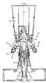
Fig. 1 is the block diagram according to some embodiment's of present technique expander system, and this expander system has and comprises the axial maintenance system that is used for cover plate, and it has reduced the quantity that part is installed to greatest extent;
Fig. 2 is the cross sectional side view according to some embodiment's of present technique expander system as shown in fig. 1;
Fig. 3 is the cross sectional side view of the turbine section that intercepted in the line 3-3 in Fig. 2 according to some embodiment of present technique;
Fig. 4 is cover plate that is intercepted in the line 4-4 in Fig. 3 according to some embodiment of present technique and the cross sectional side view that axially keeps the ring bodies assembly;
Fig. 5 is the front elevation of a part before engaging according to some embodiment's of present technique axial maintenance ring bodies assembly as shown in Figure 4;
Fig. 6 is the front elevation of a part after engaging according to some embodiment's of present technique axial maintenance ring bodies assembly as shown in Figure 4;
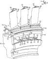
Fig. 7 is that wherein, projection passes the hole in the cover plate according to some embodiment's of present technique the perspective view that is connected to the cover plate on rotor and the wheel blade as shown in Figure 3;
Fig. 8 is being connected on rotor and the wheel blade and having the perspective view of the cover plate that is connected to first ring bodies on the projection as shown in Figure 3 according to some embodiment of present technique;
Fig. 9 is being connected on rotor and the wheel blade and having the perspective view of the cover plate that is connected to second ring bodies on the projection as shown in Figure 3 according to some embodiment of present technique;
Figure 10 is the detail section side view according to the alternative of some embodiment's of present technique rotor and projection, wherein, projection rotor with the roughly relative axial side of first cover plate on be connected on second cover plate;
Figure 11 is the detail section side view according to the another embodiment of some embodiment's of present technique rotor and projection, and wherein, projection axially keeps the ring bodies assembly to be fixed on second cover plate by second; And
Figure 12 is the detail section view according to the another embodiment of some embodiment's of present technique rotor and projection, and wherein, crooked projection extends to another cover plate from a cover plate on the roughly relative axial side of rotor.
Embodiment
One or more specific embodiment of the present invention hereinafter will be described.For the concise and to the point description to these embodiments is provided, all features of actual implementation may not described in the specification.Will be appreciated that, in the exploitation of the actual implementation of any of these, as in any engineering or the design object, must make the special decision of many implementations, to realize developer's specific objective, as follow about system with about the constraint of commerce, this can become another implementation from an implementation.In addition, will be appreciated that these developments may be very complicated and consuming time, but for the those of ordinary skill of the interests of enjoying present disclosure, still be design, the normal work to do making and produce.
When introducing various embodiments' of the present invention element, word " ", " one ", " being somebody's turn to do ", and " described " means and has one or more in these elements.Term " comprises ", " comprising ", and " having " to be intended to be comprising property, and mean existence other element except that listed element.
The embodiment of present disclosure can in axial direction be fixed to cover plate on the member (for example, rotor, wheel blade, other cover plate etc.) of turbine stage with the minimized number part.The number that reduces union piece to greatest extent can reduce these parts fall into turbogenerator during safeguarding possibility.Some embodiment can utilize and be connected to epitrochanterian projection cover plate is fixed on the turbine stage.Each projection all can comprise bar portion and the size head greater than bar portion.Projection can pass the hole in the cover plate, and by the interlocking device cover plate is fixed on the rotor, this interlocking device with the projection lock-bit between cover plate and projection head.In other embodiments, projection can comprise the bent stick portion of head towards the wheel blade bias voltage.In this structure, the head of projection can push against the interlocking device, thereby cover plate is remained on the wheel blade.In another embodiment, may use the ring bodies assembly in conjunction with projection, so that cover plate is fixed on the turbine stage.The ring bodies assembly can comprise a pair of interlocking ring bodies, and it provides the hole when interlocking.Projection can pass these holes cover plate is fixed on the rotor.For example, first ring bodies and second ring bodies can be along opposite circumferencial direction rotations, so that make projection lock-bit and fixing.Additional embodiments can utilize the projection that is connected on wheel blade and/or other cover plate to come securing cover plate in axial direction.
Now forward accompanying drawing to, and, show the embodiment's of gas turbine engine systems 10 block diagram at first referring to Fig. 1.This figure comprises fuel nozzle 12, fuel source 14, and burner 16.As shown in the figure, fuel source 14 is carried liquid fuels and/or such as the gaseous fuel of rock gas, is entered in the burner 16 via fuel nozzle 12 to expander system 10.Burner 16 is lighted and the combustion fuel air mixture, and the pressurization discharge gas of heat is entered in the turbine 18.Discharge gas passes the turbine blade in the turbine 18, thereby drives turbine 18 rotations.In the present embodiment, cover plate is mounted to contiguous turbine blade, so that stop that hot combustion gas enters turbine blade is connected in the rotor of axle on 19.As hereinafter discussing in detail like that, the embodiment of expander system 10 comprises some structures and the member that turbine 18 is interior, and they have reduced the number that cover plate is connected to the part on 18 grades of the turbines.Blade in the turbine 18 with will cause axle 19 rotations axle connecting between 19, as shown in the figure, axle 19 also is connected on a plurality of members of whole expander system 10.At last, the exhaust of combustion process can be flowed out expander system 10 via exhaust outlet 20.
In an embodiment of expander system 10, compressor vanes or blade are as the member of compressor 22 and included.Blades in the compressor 22 can be connected on the axle 19, and will be subjected to that turbine 18 drives and be rotated during rotation at axle 19.Compressor 22 can be incorporated into air in the expander system 10 via air intlet 24.In addition, axle 19 can be connected in the load 26, and this load 26 can be provided with power by the rotation of axle 19.As recognized, load 26 can be any suitable device that can generate power by the rotation output of expander system 10, generates equipment or exterior mechanical load as power.For example, load 26 can comprise generator, properller etc.Air intlet 24 is introduced air 30 in the expander system 10 by the suitable mechanism such as inlet of cold air, is used for by fuel nozzle 12 air 30 being mixed mutually with fuel source 14 subsequently.As will be described in further detail below such, the air 30 that is absorbed by expander system 10 can carry out feed and be compressed into forced air by the rotation blades in the compressor 22.As shown in arrow 32, forced air can be fed in the fuel nozzle 12 then.Fuel nozzle 12 can mix forced air and fuel (being illustrated by label 34) then, is used for burning to produce suitable ratio of mixture, for example, impels the fuel burning of after-flame more completely, in order to avoid waste fuel or produce too much effulent.
Fig. 2 shows the embodiment's of expander system 10 cross sectional side view.As shown in the figure, embodiment comprises compressor 22, and it is connected on the burner 16 of annular array, for example six, eight, ten or 12 burners 16.Each burner 16 includes at least one fuel nozzle 12 (for example, 1,2,3,4,5,6,7,8,9,10 or more), and the zone of combustion that is positioned at each burner 16 supplied with air-fuel mixture by this fuel nozzle 12.The burning of the air-fuel mixture in the burner 16 will impel stator or the blade in the turbine 18 to be rotated when discharging gas towards exhaust outlet 20 transmission.As hereinafter discussing in detail like that, some embodiment of turbine 18 comprises the multiple unique device that cover plate is connected to the number of parts on 18 grades of the turbines in order to minimizing.
Fig. 3 has presented the detail section view of the turbine 18 that is intercepted in the line 3-3 in Fig. 2.As shown in arrow 36, in axial direction 35 flow in the turbines 18 from the hot gas of burner 16.The turbine 18 that illustrates in the present embodiment comprises three turbine stage.Yet, only show initial two-stage among Fig. 3.Other turbine structure can comprise more or less turbine stage.For example, turbine can comprise 1,2,3,4,5,6 or more turbine stage.First turbine stage comprises around turbine 18 41 roughly equidistantly isolated nozzle 38 and wheel blades 40 along the circumferential direction.First order turbine nozzle 38 is installed on the turbine 18 rigidly, and is configured in order to guide combustion gas towards wheel blade 40.First order wheel blade 40 is installed on the rotor 42, and rotor 42 is by the combustion gases drive that flows through wheel blade 40.Then, rotor 42 is connected to again on the axle 19 of Driven Compressor 22 and load 26.Combustion gas flow through second level nozzle 44 and second level wheel blade 46 then.Second level wheel blade 46 also is connected on the rotor 42.At last, combustion gas flow through nozzle and the wheel blade (not shown) of the third level.When combustion gas flow through when at different levels, be transformed into the energy of rotation of rotor 42 from the energy of combustion gas.After passing each turbine stage, combustion gas are 35 outflow turbines 18 in axial direction.
Each first order wheel blade 40 includes aerofoil profile portion 48, platform 50 and shank 52.Cover plate 54 is mounted to contiguous shank 52 and rotor 42, and in axial direction 35 and radial direction 37 fixing.Cover plate 54 can comprise Sealing or the angel's wing (angel wing) 56 that is configured to enter in order to the prevention hot combustion gas rotor 42.Cover plate 54 in axial direction 35 is fixed on the wheel blade 40 by the combination of axial maintenance ring bodies assembly 58 and projection 60.As hereinafter institute's argumentation in detail, projection 60 can be connected on rotor 42, shank 52 or second cover plate on the roughly relative axial side of wheel blade 40.In axial direction the projection 60 of 35 orientations passes the hole in the cover plate 54, and is fixed by axial maintenance ring bodies assembly 58.Axially keep ring bodies assembly 58 can comprise single ring bodies, it has the usefulness of being configured to so that the groove of projection 60 lock-bits.As alternative, axially keep ring bodies assembly 58 can comprise a pair of interlocking ring bodies, the opening that holds projection 60 or make projection 60 lock-bits in order to provide is provided for it, thereby cover plate 54 is fixed on the wheel blade 40.Axially keep ring bodies assembly 58 can stop that also hot combustion gas enters the hole in the cover plate 54.In arbitrary structure in both, cover plate 54 in axial direction 35 is fixed and is not used bolt, screw or the pin that may fall into turbine 18 during safeguarding.
As shown in the figure, each cover plate 54 all radially 37 is fixed on the wheel blade 40 by hook or lug (tab) link.Particularly, cover plate 54 comprises the hook 62 that the radially inner side that is positioned at cover plate 54 is partly located.Hook 62 is configured in order to interlock with the lug 64 that is arranged on the rotor 42.In this way, when the centrifugal force from rotary turbine radially outwards promotes cover plate 54, contacting and limited cover plate 54 37 motion radially between hook 62 and the lug 64.Therefore, cover plate 54 radially 37 and axial direction 35 fixing.
Fig. 4 is projection 60, cover plate 54 that is intercepted in the line 4-4 in Fig. 3 and the detail section side view that axially keeps ring bodies assembly 58.In this embodiment, projection 60 is connected on the rotor 42.As shown in the figure, cover plate 54 comprises hole 66, and axially keeps ring bodies assembly 58 to comprise hole 68.Projection 60 comprises bar portion 70 and head 72.The diameter 67 of head 72 is less than the diameter 69 of cover board hole 66.In this structure, cover plate 54 can aim at and make cover plate 54 and rotor 42 in axial direction 35 to move towards each other and be arranged to adjacent rotor 42 by making hole 66 with projection 60.As a result, projection 60 passes the hole 66 in the cover plate 54, makes cover plate 54 to be fixed on the rotor 42 by axial maintenance ring bodies assembly 58.As shown in the figure, axially keep the diameter 73 of the diameter 71 in the hole 68 in the ring bodies assembly 58 greater than bar portion 70, but less than the diameter 67 of head 72.In this structure, axially keep ring bodies assembly 58 can make bar portion 70 lock-bits, head 72 stops ring bodies assembly 58 35 translation in axial direction simultaneously.In addition, the length 75 of bar portion 70 roughly is similar to cover plate 54 width 77 and the axially combination of maintenance ring bodies assembly 58 width 79.Therefore, when axial maintenance ring bodies assembly 58 is fixed in the bar portion 70, axially keep ring bodies assembly 58 to stop cover plate 54 35 translation in axial direction by contacting between ring bodies assembly 58 and the head 72.Therefore, during working service not, may fall under the situation of bolt, screw, pin or other fastening piece of turbine 18 and in axial direction 35 fixed cover plate 54.
Fig. 5 shows the front elevation of a part before engaging of axial maintenance ring bodies assembly 58.Axially keep ring bodies assembly 58 to extend, or be divided into a plurality of sections around the whole circumferential scope (for example, 360 degree) of turbine stage.For example, axially keep ring bodies assembly 58 can comprise 1,2,3,4,5,6,7,8,9,10 or multi-region section more.In addition, axially keep ring bodies assembly 58 to comprise having hook cover plate 54 being fixed to the single ring bodies on the projection 60, or with so that a pair of interlocking ring bodies of projection 60 lock-bits.The representative of structure shown in Fig. 5 has the axial maintenance ring bodies assembly 58 of a pair of interlocking ring bodies, and this a pair of interlocking ring bodies 58 is configured to so that projection 60 lock-bits and cover plate 54 is fixed on the turbine stage.Particularly, axially keep ring bodies assembly 58 to comprise being configured to first ring bodies 74 with second ring bodies, 76 interlockings.First ring bodies 74 comprises the first interlocking device 78 with hook 80 and recess 82.Second ring bodies 76 comprise have groove 86, the second interlocking device 84 of lug 88 and recess 90.The first interlocking device 78 is configured in order to being complementary with the second interlocking device 84, so that projection 60 lock-bits and cover plate 54 is fixed on the rotor 42.Particularly, for ring bodies 74 and 76, the first ring bodies 74 41 the spin axis rotations along the circumferential direction on direction 92 of interlocking around expander system 10.Equally, second ring bodies 76,41 spin axiss rotations along the circumferential direction on roughly relative direction 94 with direction 92 around expander system 10.Hook 80 is configured in order to being engaged in the groove 86, and lug 88 is configured in order to be engaged in the recess 82.As hereinafter will discussing in detail, when the first interlocking device 78 engaged the second interlocking device 84, recess 90 provided and is configured to use so that the hole 68 of projection 60 lock-bits.In this structure, cover plate 54 can be fixed on the turbine stage under the situation of not using a plurality of pins, bolt or other fastening piece that may fall into turbine 18 during safeguarding, thereby has eliminated the possibility that removes these fastening pieces that fall into expensive and dismantlement work consuming time.
Fig. 6 shows the front elevation of a part after engaging of axial maintenance ring bodies assembly 58.As shown in the figure, hook 80 is arranged in the groove 86, and lug 88 is arranged in the recess 82.Recess 90, lug 88 and recess 82 form and are configured to use so that the hole 68 of projection 60 lock-bits.Joint between the various members of the first interlocking device 78 and the second interlocking device 84 has stopped ring bodies 74 37 motions with respect to ring bodies 76 radially.Yet in order to stop 41 rotations with respect to second ring bodies 76 along the circumferential direction of first ring bodies 74, pin (dowel) 98 can be arranged to pass ring bodies 74 and 76.In some embodiments, pin 98 can first the interlocking device 78 with second the interlocking device 84 engage after the insertion.Pin 98 can comprise makes first ring bodies 74 be attached to structure on second ring bodies 76 rigidly.In this structure, pin 98 can get out so that the first interlocking device 78 is taken out from the second interlocking device 84, in order to remove axial maintenance ring bodies assembly 58 and cover plate 54.A plurality of pins 98 can center on the circumferential registration of ring bodies assembly 58, and at least one pin 98 all is set in each section.Some embodiment can use 1,2,3,4,5,6,7,8 at each section, 9,10 or multi-pin nail 98 more.Yet the number that reduces pin 98 has to greatest extent reduced pin 98 falls into turbine 18 during safeguarding possibility.Therefore, this is configured with and helps utilize the fastening piece of minimal amount that cover plate 54 is attached on the turbine stage, thereby reduces the possibility of dismounting turbine expensive and consuming time.
Fig. 7 shows the perspective view that is connected to the cover plate 54 on rotor 42 sections.Although only show a section of rotor 42, what will be appreciated that is that rotor 42 is annular, and extends around the whole circumference of turbine 18.In addition, although a cover plate 54 has been shown among Fig. 7, embodiment can comprise a plurality of cover plates 54 that are adjacent to each other around the circumferential scope of rotor 42.For example, some embodiment can comprise that centering on rotor 42 jointly extends 5,10,15,20 of 360 degree, 25,30 or more cover plates.As shown in the figure, cover plate 54 is 41 extensions along the circumferential direction, so that roughly cover three wheel blades 40.Other embodiment can use and roughly cover 1,2,4,5, the cover plate 54 of 6,7,8 or more wheels leaf 40.In addition, each circumferential end 100 of cover plate 54 departs from the circumferential end 102 of wheel blade 40.In this structure, the interface between the cover plate 54 can not overlap with the interface between the wheel blade 40.Because hot combustion gas can not pass the interface of cover plate and wheel blade, so this layout can help to strengthen the thermal protection to rotor 42.
Be similar to the described embodiment with reference to Fig. 3, projection 60 is connected on the rotor 42.Projection 60 passes the hole 66 in the cover plate 54, so that cover plate 54 is fixed on the rotor 42.Present embodiment has used three projections 60 that each cover plate 54 is attached on the rotor 42.Constructive alternative can use 1,2,4,5,6,7,8,9,10 or more projections 60 on each cover plate 54.In addition, other embodiment can use the projection 60 that is connected to integratedly on wheel blade 40 shanks 52.In other words, projection 60 can form the part (that is integral type) of wheel blade 40 during the wheel blade manufacture process.Be similar to the structure of rotor projection, each wheel blade 40 all can comprise and is connected to 1,2,3,4 on the shank 52,5,6 or more projections 60.As hereinafter described in detail, additional embodiments can be used the projection 60 that is connected on another cover plate, and this another cover plate is arranged on the roughly relative axial side of rotor 42.
Fig. 8 shows and utilizes first ring bodies 74 to be connected to the perspective view of the cover plate 54 on rotor 42 sections.As shown in the figure, show the section of first ring bodies 74.Some embodiment can use the complete annular ring bodies 74 that extends around the whole circumference scope of rotor 42.Alternative can adopt a series of ring bodies sections of the circumference range that centers on rotor 42 that makes each projection 60 lock-bit.
For example, as shown in the figure, a ring bodies section can be configured to use so that pass all projection 60 lock-bits of a cover plate 54.Alternative ring bodies section can be configured to so that with 2,3,4,5,6,7,8,9, all projection 60 lock-bits that 10 or more cover plates 54 are associated.Additional embodiments can adopt the ring bodies section of a part of lock-bit that only makes the projection 60 that is associated with each cover plate 54.For example, some embodiment can use 1,2,3,4 on each cover plate 54,5 or multi-annular tagma section more.
The individual section of ring bodies 74 or ring bodies 74 can be connected on the projection 60 by the first interlocking device 78 is aimed at along direction 92 and projection 60 and the ring bodies 74 that rotates or its each section.The first interlocking device 78 is configured to so that projection 60 lock-bits, thereby cover plate 54 is in axial direction 35 fixing.Some embodiment can use single ring bodies system, makes ring bodies 74 or its section be operable to individually in order to securing cover plate 54.For example, the diameter of recess 82 can be roughly similar to the diameter 73 of projection 60 bar portions 70.Because the diameter 67 of projection 60 heads 72 is greater than the diameter 73 of bar portion 70, so the interaction between the head 72 and the first interlocking device 78 can limit the axial motion of ring bodies 74, thus securing cover plate 54.As alternative, as hereinafter described in detail, first ring bodies 74 can with second ring bodies 76 interlocking so that make projection 60 lock-bits and cover plate 54 be fixed on the rotor 42.Arbitrary structure among both is 35 securing cover plates 54 in axial direction effectively all, have limited the number that may fall into the part of turbine 18 during safeguarding simultaneously.
Fig. 9 shows to utilize and comprises that the ring bodies assembly 58 of first ring bodies 74 and second ring bodies 76 is connected to the perspective view of the cover plate 54 on rotor 42 sections.As mentioned before, first ring bodies 74 comprises the first interlocking device 78, and second ring bodies 76 comprises the second ring bodies device 84.In some embodiments, second ring bodies 76 can adopt the mode segmentation similar to first ring bodies 74.After the first interlocking device 78 of ring bodies 74 made projection 60 lock-bits, second ring bodies 76 can be installed cover plate 54 is fixed on the rotor 42.Particularly, second of the ring bodies 76 interlocking device 84 can be aimed at the projection 60 and the first interlocking device 78.Ring bodies 76 or its section can engage the first interlocking device 78 up to the second interlocking device 84 along direction 94 rotations then.The first interlocking device 78 and the second interlocking device 84 are configured in order to hole 68 to be provided when interlocking.The diameter 71 in hole 68 is greater than the diameter 73 of bar portion 70, but less than the diameter 67 of head 72.Therefore, the interaction between head 72 and the ring bodies assembly 58 can limit the axial motion of ring bodies assembly 58.In this structure, ring bodies assembly 58 can be fixed to cover plate 54 on the rotor 42 and need not to use the finding that may fall in the turbine 18 during safeguarding.In addition, as indicated above, pin can be arranged to pass ring bodies 74 and 76 vertically, so that stop a ring bodies rotating in a circumferential direction with respect to another ring bodies.
Figure 10 is the detail section side view of the alternative of rotor 42 and projection 60, and wherein, projection 60 is connected on second cover plate 104 on the axial side roughly relative with first cover plate 54 of rotor 42.Particularly, cover plate 54 is installed on downstream (that is, the flow direction of the hot combustion gas) axial side of rotor 42, and cover plate 104 is installed on the axial side of upstream.In this structure, projection 60 is connected on the cover plate 104 rigidly, and comprises the bar portion 70 that extends to another axial side from an axial side of rotor 42.The projection 60 that extends passes the hole 106 in the rotor 42.The diameter 108 in hole 106 makes projection 60 to pass hole 106 at assembly process greater than the diameter 67 of projection 60 heads 72.Be similar to the foregoing description, projection 60 passes hole 66 and the axial hole 68 that keeps in the ring bodies assembly 58 in the cover plate 54.In this structure, when axial maintenance ring bodies assembly 58 is fixed in the bar portion 70, axially keep ring bodies assembly 58 to stop cover plate 54 35 translation in axial direction by contacting between ring bodies assembly 58 and the head 72.In addition, because cover plate 104 is connected on the projection 60 rigidly and is arranged to adjacent rotor 42, so contact the axial motion that can stop cover plate 104 between ring bodies assembly 58 and the head 72.Therefore, cover plate 54 and 104 in axial direction 35 is subjected to fixing and need not to use bolt, screw, pin or other fastening piece that may fall into turbine 18 during safeguarding.
Figure 11 shows the another embodiment's of rotor 42 and projection 60 detail section side view, and wherein, projection 60 axially keeps ring bodies assembly 110 to be fixed on second cover plate 104 by second.In this structure, projection 60 comprises first head 72 and second head 112.Be similar to previously described embodiment, projection 60 passes hole 66 and the axial hole 68 that keeps in the ring bodies assembly 58 in the cover plate 54.In addition, projection 60 passes hole 114 and the axial hole 116 that keeps in the ring bodies assembly 110 in the cover plate 104.When axial maintenance ring bodies assembly 58 and 110 is fixed on the roughly relative end of bar portion 70, axially keep ring bodies assembly 58 and 110 by between ring bodies assembly 58 and the head 72 contact and ring bodies assembly 110 and head 112 between contact and stop cover plate 54 and 104 35 translation in axial direction.Therefore, cover plate 54 and 104 in axial direction 35 is subjected to fixing and need not to use bolt, screw, pin or other fastening piece that may fall into turbine 18 during safeguarding.Additional embodiments can be used the combination of projection attachment point.For example, some embodiment can comprise the projection 60 that is connected on rotor 42 and the wheel blade 40.Other embodiment can use the projection 60 that extends to cover plate 104 from cover plate 54, and is connected to the projection 60 on the wheel blade 40.
Some embodiment can use crooked projection or the elasticity projection towards cover plate 54 bias voltage ring bodies assemblies 58.For example, Figure 12 has presented the another embodiment's of rotor 42 and projection 60 detail section side view, and wherein, crooked projection 60 extends to cover plate 104 from cover plate 54.In an illustrated embodiment, projection 60 passes the hole 118 in wheel blade 40 shanks 52.As seen in Figure 11, hole 118 and 114 shape specifically are configured in order to adapt to the curved shape of projection 60.The attach procedure of cover plate can comprise power 120 radially 37 is applied to crooked projection 60 and reduces tortuosity, thereby prolong the length of crooked projection 60. Cover plate 54 and 104 and ring bodies assembly 58 and 110 can carry out attached then.Power 120 can be removed from crooked projection 60 then, thereby impels crooked projection 60 to come bias voltage ring bodies assembly 58 and 110 towards cover plate 54 and 104 respectively.Similar arrangements can be used for being connected to the projection 60 on rotor 42 and the wheel blade 40.As alternative, elasticity projection 60 can be used for coming bias voltage ring bodies assembly 58 and 110 towards cover plate 54 and 104 respectively.The elasticity projection can be by projection 60 can be constituted along the material that its longitudinal axis stretches.Image curvature projection 60 is the same, and at assembly process, the power that can apply before attached ring bodies assembly 58 and 110 makes elasticity projection 60 35 stretching, extensions in axial direction.After ring bodies assembly 58 and 110 is fixed on the rotor 42, can removes power, thereby cause that elasticity projection 60 comes bias voltage ring bodies assembly 58 and 110 towards cover plate 54 and 104 respectively.This structure can strengthen the maintenance to ring bodies assembly 58 and 110.
Additional embodiments can use alternative interlock system that cover plate 54 is fixed on the rotor 42.For example, alternative segmented ring bodies can comprise that radially inside direction is directed and center on ring bodies along circumferential isolated interlocking device.For attachment of hd 54, the interlocking device in the section of alternative ring bodies can be aimed at projection 60.Can radially inwardly guide ring bodies then, the feasible device of respectively interlocking makes the projection lock-bit.This structure can reduce the number that falls into the part in the turbine 18 during the maintenance.Be configured to so that projection 60 lock-bits and in axial direction the other alternative interlock system of 35 securing cover plates 54 can in alternative, use.
This written explanation has used the example that comprises optimal mode to come open the present invention, and also enables those skilled in the art to implement the present invention, comprises making and uses any device or system, and carry out any method that combines.Claim of the present invention is defined by the claims, and can comprise other example that those skilled in the art visualizes.If having with the written language of claim, these other example there is no different structural elements, if perhaps these other example comprises that the written language with claim does not have the equivalent constructions element of essence difference, think that then these examples drop within the scope of claim.
Claims (10)
1. system comprises:
Turbogenerator (10) comprising:
Turbine stage, it comprises having the turbine rotor (42) that is circular layout a plurality of blades (40) of being provided with first;
A plurality of cover plates (54), its along the interface between described turbine rotor (42) and the described blade (40) with second setting that is circular layout;
Be connected to a plurality of projections (60) on the described turbine stage; And
First ring bodies (74), it is connected to described a plurality of projection (60) and goes up so that described a plurality of cover plates (54) are remained on the described turbine stage.
2. system according to claim 1, it is characterized in that, described a plurality of projection (60) extends through the described turbine stage between relative axial side vertically, and described a plurality of projection (60) is fixed on described relative axial side on the two with cover plate (54,104).
3. system according to claim 1 is characterized in that, described a plurality of projections (60) comprise the elastic element that is configured in order to towards the corresponding projection of the inside bias voltage of described turbine stage (60) respectively.
4. system according to claim 1, it is characterized in that, described first ring bodies (74) comprises a plurality of first interlocking devices (78), and described first ring bodies (74) is configured to make described a plurality of projection (60) lock-bit at least in part in order to center on the spin axis rotation of described turbine stage along first direction (92) up to the described first interlocking device (78).
5. system according to claim 4, it is characterized in that, described system comprises second ring bodies (76) with a plurality of second interlocking devices (84), described second ring bodies (76) is configured in order to the rotation of the spin axis along second direction (94) around described turbine stage, make described a plurality of projection (60) lock-bit at least in part up to the described second interlocking device (84), described first direction (92) and described second direction (94) toward each other, and each all is arranged in the relative peripheral side that both rotations of described first ring bodies (74) and described second ring bodies (76) center on afterwards each corresponding projection (60) to the first interlocking device (78) and the second interlocking device (84).
6. system according to claim 5, it is characterized in that, described first ring bodies (74) is segmented into and limits a plurality of ring bodies sections of the 3rd first group of being circular layout, and described second ring bodies (76) is segmented into the second group of a plurality of ring bodies section that limits Fourth Ring shape layout.
7. system comprises:
Turbine stage comprises:
Projection (60), it has bar portion (70) and the size head (72) greater than described bar portion (70), wherein, described bar portion (70) and described head (72) are configured to extend through cover plate (54), and described projection (60) is configured to be positioned at interlocking device (78) between described cover plate (54) and the described head (72) in order to reception, so that described cover plate (54) is remained on the described turbine stage.
8. system according to claim 7, it is characterized in that, described system comprises that turbine rotor (42) along described turbine stage and the interface between the blade (40) are with the first a plurality of cover plates (54) that are circular layout and are provided with, wherein, described turbine stage comprises a plurality of projections (60) that are circular layout and are provided with second, and each projection (60) all is configured to be positioned at corresponding interlocking device (78) between the head (72) of corresponding cover plate (54) and described projection (60) in order to reception.
9. system according to claim 7 is characterized in that, described system comprises first ring bodies (74) with described interlocking device (78).
10. system according to claim 9, it is characterized in that, described system comprise be configured in order to second ring bodies (76) of described first ring bodies (74) interlocking, wherein, described first ring bodies (74) and described second ring bodies (76) are along relative direction (92,94) rotation is so that described projection (60) lock-bit.
Applications Claiming Priority (2)
| Application Number | Priority Date | Filing Date | Title |
|---|---|---|---|
| US12/392,956 | 2009-02-25 | ||
| US12/392,956 US8277191B2 (en) | 2009-02-25 | 2009-02-25 | Apparatus for bucket cover plate retention |
Publications (1)
| Publication Number | Publication Date |
|---|---|
| CN101818659A true CN101818659A (en) | 2010-09-01 |
Family
ID=42224897
Family Applications (1)
| Application Number | Title | Priority Date | Filing Date |
|---|---|---|---|
| CN201010135833A Pending CN101818659A (en) | 2009-02-25 | 2010-02-25 | Be used to keep the device of bucket cover plate |
Country Status (4)
| Country | Link |
|---|---|
| US (1) | US8277191B2 (en) |
| EP (1) | EP2224098A3 (en) |
| JP (1) | JP2010196701A (en) |
| CN (1) | CN101818659A (en) |
Cited By (3)
| Publication number | Priority date | Publication date | Assignee | Title |
|---|---|---|---|---|
| CN103075201A (en) * | 2011-10-26 | 2013-05-01 | 通用电气公司 | Turbine cover plate assembly |
| CN103485832A (en) * | 2012-06-12 | 2014-01-01 | 通用电气公司 | Blade attachment assembly |
| CN107420136A (en) * | 2016-05-09 | 2017-12-01 | 曼柴油机和涡轮机欧洲股份公司 | Combustion gas turbine |
Families Citing this family (9)
| Publication number | Priority date | Publication date | Assignee | Title |
|---|---|---|---|---|
| DE102011077501A1 (en) * | 2011-06-14 | 2012-12-20 | Rolls-Royce Deutschland Ltd & Co Kg | Rotor device for a jet engine with a disc wheel and a plurality of blades |
| US20130256996A1 (en) * | 2012-03-28 | 2013-10-03 | General Electric Company | Shiplap plate seal |
| US9181810B2 (en) | 2012-04-16 | 2015-11-10 | General Electric Company | System and method for covering a blade mounting region of turbine blades |
| US9366151B2 (en) | 2012-05-07 | 2016-06-14 | General Electric Company | System and method for covering a blade mounting region of turbine blades |
| US9212562B2 (en) | 2012-07-18 | 2015-12-15 | United Technologies Corporation | Bayoneted anti-rotation turbine seals |
| US9567857B2 (en) | 2013-03-08 | 2017-02-14 | Rolls-Royce North American Technologies, Inc. | Turbine split ring retention and anti-rotation method |
| WO2014168862A1 (en) | 2013-04-12 | 2014-10-16 | United Technologies Corporation | Cover plate for a rotor assembly of a gas turbine engine |
| WO2015020931A2 (en) | 2013-08-09 | 2015-02-12 | United Technologies Corporation | Cover plate assembly for a gas turbine engine |
| KR102036193B1 (en) * | 2017-12-18 | 2019-10-24 | 두산중공업 주식회사 | Turbine apparatus |
Citations (6)
| Publication number | Priority date | Publication date | Assignee | Title |
|---|---|---|---|---|
| GB589689A (en) * | 1944-03-31 | 1947-06-26 | British Thomson Houston Co Ltd | Improvements in and relating to centrifugal compressors |
| US3137478A (en) * | 1962-07-11 | 1964-06-16 | Gen Electric | Cover plate assembly for sealing spaces between turbine buckets |
| CN1080017A (en) * | 1992-01-08 | 1993-12-29 | 阿尔斯托姆有限公司 | The thrust steam turbine that is used for being installed on the drum type rotor of the interior blade of cannelure having of thrust steam turbine and comprises this rotor |
| US6190131B1 (en) * | 1999-08-31 | 2001-02-20 | General Electric Co. | Non-integral balanced coverplate and coverplate centering slot for a turbine |
| JP2007231868A (en) * | 2006-03-02 | 2007-09-13 | Hitachi Ltd | Steam turbine bucket, steam turbine using the same and steam turbine power generation plant |
| CN101349171A (en) * | 2007-07-19 | 2009-01-21 | 通用电气公司 | Clamped plate seal |
Family Cites Families (7)
| Publication number | Priority date | Publication date | Assignee | Title |
|---|---|---|---|---|
| GB954323A (en) * | 1962-03-17 | 1964-04-02 | Rolls Royce | Improvements in or relating to bladed rotors for fluid flow machines such as turbines |
| US4192633A (en) * | 1977-12-28 | 1980-03-11 | General Electric Company | Counterweighted blade damper |
| US5993160A (en) * | 1997-12-11 | 1999-11-30 | Pratt & Whitney Canada Inc. | Cover plate for gas turbine rotor |
| GB9925261D0 (en) * | 1999-10-27 | 1999-12-29 | Rolls Royce Plc | Locking devices |
| GB2410984B (en) * | 2004-02-14 | 2006-03-08 | Rolls Royce Plc | Securing assembly |
| FR2868808B1 (en) * | 2004-04-09 | 2008-08-29 | Snecma Moteurs Sa | DEVICE FOR THE AXIAL RETENTION OF AUBES ON A ROTOR DISC OF A TURBOMACHINE |
| US7806662B2 (en) * | 2007-04-12 | 2010-10-05 | Pratt & Whitney Canada Corp. | Blade retention system for use in a gas turbine engine |
-
2009
- 2009-02-25 US US12/392,956 patent/US8277191B2/en active Active
-
2010
- 2010-02-18 JP JP2010033076A patent/JP2010196701A/en active Pending
- 2010-02-23 EP EP10154316.3A patent/EP2224098A3/en not_active Withdrawn
- 2010-02-25 CN CN201010135833A patent/CN101818659A/en active Pending
Patent Citations (6)
| Publication number | Priority date | Publication date | Assignee | Title |
|---|---|---|---|---|
| GB589689A (en) * | 1944-03-31 | 1947-06-26 | British Thomson Houston Co Ltd | Improvements in and relating to centrifugal compressors |
| US3137478A (en) * | 1962-07-11 | 1964-06-16 | Gen Electric | Cover plate assembly for sealing spaces between turbine buckets |
| CN1080017A (en) * | 1992-01-08 | 1993-12-29 | 阿尔斯托姆有限公司 | The thrust steam turbine that is used for being installed on the drum type rotor of the interior blade of cannelure having of thrust steam turbine and comprises this rotor |
| US6190131B1 (en) * | 1999-08-31 | 2001-02-20 | General Electric Co. | Non-integral balanced coverplate and coverplate centering slot for a turbine |
| JP2007231868A (en) * | 2006-03-02 | 2007-09-13 | Hitachi Ltd | Steam turbine bucket, steam turbine using the same and steam turbine power generation plant |
| CN101349171A (en) * | 2007-07-19 | 2009-01-21 | 通用电气公司 | Clamped plate seal |
Cited By (9)
| Publication number | Priority date | Publication date | Assignee | Title |
|---|---|---|---|---|
| CN103075201A (en) * | 2011-10-26 | 2013-05-01 | 通用电气公司 | Turbine cover plate assembly |
| US9217334B2 (en) | 2011-10-26 | 2015-12-22 | General Electric Company | Turbine cover plate assembly |
| CN103075201B (en) * | 2011-10-26 | 2016-08-03 | 通用电气公司 | turbine cover plate assembly |
| CN103485832A (en) * | 2012-06-12 | 2014-01-01 | 通用电气公司 | Blade attachment assembly |
| US9328622B2 (en) | 2012-06-12 | 2016-05-03 | General Electric Company | Blade attachment assembly |
| CN103485832B (en) * | 2012-06-12 | 2017-04-12 | 通用电气公司 | Blade attachment assembly |
| US10215036B2 (en) | 2012-06-12 | 2019-02-26 | General Electric Company | Blade attachment assembly |
| CN107420136A (en) * | 2016-05-09 | 2017-12-01 | 曼柴油机和涡轮机欧洲股份公司 | Combustion gas turbine |
| CN107420136B (en) * | 2016-05-09 | 2021-02-26 | 曼恩能源方案有限公司 | Gas turbine |
Also Published As
| Publication number | Publication date |
|---|---|
| US8277191B2 (en) | 2012-10-02 |
| JP2010196701A (en) | 2010-09-09 |
| US20100215501A1 (en) | 2010-08-26 |
| EP2224098A2 (en) | 2010-09-01 |
| EP2224098A3 (en) | 2014-01-01 |
Similar Documents
| Publication | Publication Date | Title |
|---|---|---|
| CN101818659A (en) | Be used to keep the device of bucket cover plate | |
| US8529195B2 (en) | Inducer for gas turbine system | |
| EP2592232B1 (en) | Leaf seal for transition duct in turbine system | |
| CA2677372C (en) | Combustor liner with integrated anti-rotation and removal feature | |
| EP2530381B1 (en) | Loading assembly for a turbine system | |
| US20070130958A1 (en) | Combustor flow sleeve attachment system | |
| JP2008286199A (en) | Turbine engine cooling method and device | |
| US7272930B2 (en) | Exhaust diffuser assembly with tunable velocity profile | |
| US8707673B1 (en) | Articulated transition duct in turbomachine | |
| EP3189215B1 (en) | A transition-to-turbine seal assembly | |
| KR20180130786A (en) | Vane ring assembly and compressor and gas turbine including the same | |
| KR20170107391A (en) | Axially staged fuel injector assembly mounting | |
| US20160298853A1 (en) | Service-friendly cross flame tube with twist lock attachment for can-annular gas turbines | |
| CN102401382A (en) | Combustor assembly for use in turbine engine and methods of assembling same | |
| US20100064516A1 (en) | Stator Ring Configuration | |
| EP2653661B1 (en) | Turbomachine blade mounting system | |
| US6422812B1 (en) | Bolted joint for rotor disks and method of reducing thermal gradients therein | |
| US20150167984A1 (en) | Bundled tube fuel injector aft plate retention | |
| EP3269926B1 (en) | Disk assembly and turbine including the same | |
| US9528392B2 (en) | System for supporting a turbine nozzle | |
| EP2543824B1 (en) | Support assembly for a turbine system and corresponding turbine system | |
| CN103510994A (en) | System having blade segment with curved mounting geometry | |
| US10697634B2 (en) | Inner cooling shroud for transition zone of annular combustor liner | |
| EP3222818B1 (en) | Transition duct assembly | |
| US10982546B2 (en) | Flow-diverting systems for gas turbine air separator |
Legal Events
| Date | Code | Title | Description |
|---|---|---|---|
| C06 | Publication | ||
| PB01 | Publication | ||
| C10 | Entry into substantive examination | ||
| SE01 | Entry into force of request for substantive examination | ||
| C02 | Deemed withdrawal of patent application after publication (patent law 2001) | ||
| WD01 | Invention patent application deemed withdrawn after publication |
Application publication date: 20100901 |