CN101769128B - Connecting mechanism for dual shaft drilling machine - Google Patents
Connecting mechanism for dual shaft drilling machine Download PDFInfo
- Publication number
- CN101769128B CN101769128B CN 201010100834 CN201010100834A CN101769128B CN 101769128 B CN101769128 B CN 101769128B CN 201010100834 CN201010100834 CN 201010100834 CN 201010100834 A CN201010100834 A CN 201010100834A CN 101769128 B CN101769128 B CN 101769128B
- Authority
- CN
- China
- Prior art keywords
- connection block
- bindiny mechanism
- linking arm
- clamping cylinder
- connecting seat
- Prior art date
- Legal status (The legal status is an assumption and is not a legal conclusion. Google has not performed a legal analysis and makes no representation as to the accuracy of the status listed.)
- Active
Links
Images
Abstract
The invention relates to a connecting mechanism for a dual shaft drilling machine, which comprises a connecting arm, a connecting seat, a lifting cylinder, a clamping cylinder and a fork head, wherein the interiors of the connecting arm and the connecting seat are hollow. One end of the connecting arm is arranged on a top tray connecting seat of the drilling machine through a pin shaft, while the other end is fixedly connected with the connecting seat. The fixed end of the clamping cylinder is arranged in the connecting arm by using the pin shaft, and the fork head is arranged at the extension end of the clamping cylinder and movably placed in the connecting seat. The extension end of the lifting cylinder is arranged on the connecting arm through the pin shaft, while the other end is arranged on the top tray connecting seat through the pin shaft, and the mounting position of the lifting cylinder on the top tray connecting seat is higher than the mounting position on the connecting arm. The connecting mechanism enables two drilling frames of the dual shaft drilling machine to be connected stably and reliably, has simple operation, and can be conveniently detached and connected after the work is finished so as to relieve the labor intensity of workers and improve the work efficiency.
Description
Technical field
The invention belongs to the ore deposit and build To Construction of Silo dual shaft-well drill parts, relate in particular to the drilling cramp bindiny mechanism on the dual shaft-well drill.
Background technology
Along with the fast development of national economy, national industry-by-industry is growing to the demand of metal material.Simultaneously, because the metal mine engineering quantity is in a large number by changing underground mining in the open over to, the engineering quantity that the metal mine vertical shaft is built is also increasing fast.Although the engineering quantity that the metal mine vertical shaft is built is increasing, the rock drilling equipment that the metal mine To Construction of Silo is used does not have to be upgraded timely along with the growth of the engineering quantity of vertical shaft construction, and its equipment and technology is still relatively backward.
At present, domestic metal mine vertical shaft rock drilling construction mostly adopts air rock drill as the shaft drilling machine of drilling machine.Relative colliery, the maximum difficult point of metal mine vertical shaft rock drilling construction are because formation hardness is high, use traditional air rock drill drilling efficiency low and cause, and the while also exists labour intensity large, the shortcomings such as work under bad environment.Prior art discloses a kind of patent No. and has been " 200820134685.9 ", denomination of invention is the utility model patent of " hydraulic shaft-well drill ", comprises drilling cramp, is connected in the rock body of drilling cramp and rig power source is provided and the hydraulic pressure of driving force and water gas system and electrical system; Wherein, drilling cramp comprises that column, activity are loaded on the swing span of column, an end is connected in the swing span other end and then is connected in the swing arm of rock body and the support arm that an end is installed in swing span; Rock body comprises balladeur train and is arranged on compensation frame and the hydraulic gate of balladeur train; Hydraulic pressure and water gas system comprise establishes auxiliary hydraulic system, rock drilling hydraulic system and water pump; During work, support arm stretches out, and props up well bore wall and so that drilling cramp is stable in the well, rock body and idle rod move to bore position, and orders about lower rock drilling at the power of hydraulic pressure and water gas system and electrical system, simultaneously, and the punching landwaste at the end of water pump flushing.This utility model helps to improve workman's working environment, the degree of accuracy that improves rock drilling and productivity ratio, reduction workman's working strength, but this hydraulic shaft-well drill is the monomer rig, certainly exists the little defective of the drilling well rock drilling radius of clean-up.If two shaft drilling machines connections are in aggregates, must high requirement have been proposed to the bindiny mechanism between two shaft drilling machines.The connected mode of prior art can't guarantee steadiness, the reliability in being rigidly connected of down-hole drilling cramp and the dual shaft-well drill course of work, simultaneously behind the boring end-of-job, also can't be more convenient dismantle.
Summary of the invention
The object of the present invention is to provide a kind of bindiny mechanism of dual shaft-well drill, it can finish in the down-hole being rigidly connected of dual shaft-well drill drilling cramp, and guarantee in the rig course of work solid and reliable, work simultaneously can be more convenient after finishing the connection of taking apart, be convenient to order and hang the down-hole.
For achieving the above object, the technical scheme that adopts of invention is: a kind of bindiny mechanism of dual shaft-well drill comprises linking arm and Connection Block, hoist cylinder, clamping cylinder and the jaw of inner hollow.One end of described linking arm is installed on the Connection Block of taking over a business of rig by bearing pin, and its other end and Connection Block are fixedly linked.The fixed end of described clamping cylinder is installed in the linking arm with bearing pin, and described jaw is installed on the external part of clamping cylinder and is movably placed in the Connection Block, and when clamping cylinder stretched out, jaw forwards slided in Connection Block.The external part of described hoist cylinder is installed on the linking arm by bearing pin, and its other end is installed on Connection Block by bearing pin, and hoist cylinder is in the installation site of taking over a business installation site on the Connection Block and be higher than described linking arm.When hoist cylinder stretches, drive bindiny mechanism and centered by linking arm and the junction of taking over a business Connection Block, rotate to an angle, realize adjusting thus the purpose of jaw height.
Be connected and fixed by bolt between described linking arm and the Connection Block.
Beneficial effect of the present invention is: by this bindiny mechanism, dual shaft-well drill has been realized successful utilizations in large hole diameter To Construction of Silo, the secure and reliable connection of two drilling cramps, the while is simple to operate, work can be more convenient after finishing the connection of taking apart.Both alleviated workman's labour intensity, and improved again operating efficiency, tool has very important significance in construction application.
Description of drawings
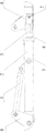
Fig. 1 is the structural representation of the bindiny mechanism of dual shaft-well drill of the present invention.
The specific embodiment
The present invention is further detailed explanation below in conjunction with the drawings and specific embodiments.
In conjunction with shown in Figure 1, the bindiny mechanism of dual shaft-well drill of the present invention comprises linking arm 5 and Connection Block 6, hoist cylinder 1, clamping cylinder 3 and the jaw 4 of inner hollow.One end of described linking arm 5 is taken over a business Connection Block 8 by what bearing pin was installed on rig, and its other end and Connection Block 6 are connected and fixed by bolt.The fixed end of described clamping cylinder 3 is installed in the linking arm 5 with bearing pin, and described jaw 4 is installed on the external part of clamping cylinder 3 and is movably placed in the Connection Block 6, drives when clamping cylinder 3 is flexible that jaw 4 approaches or away from Connection Block 6.The external part of described hoist cylinder 1 is installed on the linking arm 5 by bearing pin, and its other end is installed on Connection Block 8 by bearing pin, and hoist cylinder 1 is in the installation site of taking over a business installation site on the Connection Block 8 and be higher than described linking arm 5.When hoist cylinder 1 is flexible, drives bindiny mechanism and centered by linking arm 5 and the junction of taking over a business Connection Block 8, rotate to an angle, realize adjusting thus the purpose of jaw 4 height.
After two bench drill framves of dual shaft-well drill are gone into the well respectively, by the stable car device two bench drill framves are adjusted to suitable position first.Then start auxiliary hydraulic system and connect two drilling cramps, this bindiny mechanism is installed in the taking over a business on the Connection Block 8 of a bench drill frame of dual shaft-well drill, come the lifting of control connection mechanism to proper height by hoist cylinder 1, controlling clamping cylinder 3 stretches out again, it is forwards mobile to drive thus jaw 4, until clamp the bearing pin 7 of adjacent drilling cramp.At this moment set up between dual shaft-well drill two drilling cramps and be rigidly connected.
Behind the boring end-of-job, for conveniently hanging the down-hole, dual shaft-well drill need to be taken being rigidly connected between two drilling cramps apart.Start auxiliary hydraulic system this moment, the external part of clamping cylinder 3 is retracted, and jaw 4 leaves the bearing pin 7 of adjacent drilling cramp, then auxiliary hydraulic system is to hoist cylinder 1 rodless cavity fuel feeding, piston rod stretches out, and bindiny mechanism rotates leaves drilling cramp, and two bench drills are put up merit and separated.
The invention is not restricted to above-described embodiment; to those skilled in the art, any apparent improvement of the above embodiment of the present invention being made or change can not exceed the embodiments of the invention that only illustrate by way of example and the protection domain of claims.
Claims (2)
1. the bindiny mechanism of a dual shaft-well drill, it is characterized in that: described bindiny mechanism comprises the linking arm (5) of inner hollow and Connection Block (6), hoist cylinder (1), clamping cylinder (3) and the jaw (4) of bindiny mechanism; One end of described linking arm (5) is taken over a business Connection Block (8) by what bearing pin was installed on rig, and the Connection Block of its other end and bindiny mechanism (6) is fixedly linked; The fixed end of described clamping cylinder (3) is installed in the linking arm (5) with bearing pin; Described jaw (4) is installed on the external part of clamping cylinder (3) and is movably placed in the Connection Block (6) of bindiny mechanism; The external part of described hoist cylinder (1) is installed on the linking arm (5) by bearing pin, its other end is installed on Connection Block (8) by bearing pin, and hoist cylinder (1) is higher than described linking arm (5) and is taking over a business installation site on the Connection Block (8) taking over a business installation site on the Connection Block (8).
2. the bindiny mechanism of dual shaft-well drill as claimed in claim 1 is characterized in that: be bolted between the Connection Block (6) of described linking arm (5) and bindiny mechanism.
Priority Applications (1)
| Application Number | Priority Date | Filing Date | Title |
|---|---|---|---|
| CN 201010100834 CN101769128B (en) | 2010-01-25 | 2010-01-25 | Connecting mechanism for dual shaft drilling machine |
Applications Claiming Priority (1)
| Application Number | Priority Date | Filing Date | Title |
|---|---|---|---|
| CN 201010100834 CN101769128B (en) | 2010-01-25 | 2010-01-25 | Connecting mechanism for dual shaft drilling machine |
Publications (2)
| Publication Number | Publication Date |
|---|---|
| CN101769128A CN101769128A (en) | 2010-07-07 |
| CN101769128B true CN101769128B (en) | 2013-03-13 |
Family
ID=42502211
Family Applications (1)
| Application Number | Title | Priority Date | Filing Date |
|---|---|---|---|
| CN 201010100834 Active CN101769128B (en) | 2010-01-25 | 2010-01-25 | Connecting mechanism for dual shaft drilling machine |
Country Status (1)
| Country | Link |
|---|---|
| CN (1) | CN101769128B (en) |
Cited By (1)
| Publication number | Priority date | Publication date | Assignee | Title |
|---|---|---|---|---|
| CN105781432A (en) * | 2016-05-06 | 2016-07-20 | 江苏盖亚环境科技股份有限公司 | Hoisting mechanism of soil sampling and restoration integrated drilling machine |
Families Citing this family (1)
| Publication number | Priority date | Publication date | Assignee | Title |
|---|---|---|---|---|
| CN102996063A (en) * | 2012-12-26 | 2013-03-27 | 张家口宣化华泰矿冶机械有限公司 | Drilling mechanism for mine rock drilling and tunneling |
Citations (4)
| Publication number | Priority date | Publication date | Assignee | Title |
|---|---|---|---|---|
| EP1085168A1 (en) * | 1999-09-16 | 2001-03-21 | Compagnie Du Sol | Apparatus for taking up forces for a drilling mast |
| CN1560424A (en) * | 2004-02-19 | 2005-01-05 | 中国石油集团东方地球物理勘探有限责 | Screw off device of drilling machine |
| CN2687310Y (en) * | 2004-02-19 | 2005-03-23 | 中国石油集团东方地球物理勘探有限责任公司 | Hydraulic drill collar fork |
| CN201306118Y (en) * | 2008-09-05 | 2009-09-09 | 张家口宣化华泰矿冶机械有限公司 | Hydraulic shaft-well drill |
-
2010
- 2010-01-25 CN CN 201010100834 patent/CN101769128B/en active Active
Patent Citations (4)
| Publication number | Priority date | Publication date | Assignee | Title |
|---|---|---|---|---|
| EP1085168A1 (en) * | 1999-09-16 | 2001-03-21 | Compagnie Du Sol | Apparatus for taking up forces for a drilling mast |
| CN1560424A (en) * | 2004-02-19 | 2005-01-05 | 中国石油集团东方地球物理勘探有限责 | Screw off device of drilling machine |
| CN2687310Y (en) * | 2004-02-19 | 2005-03-23 | 中国石油集团东方地球物理勘探有限责任公司 | Hydraulic drill collar fork |
| CN201306118Y (en) * | 2008-09-05 | 2009-09-09 | 张家口宣化华泰矿冶机械有限公司 | Hydraulic shaft-well drill |
Non-Patent Citations (6)
| Title |
|---|
| > * |
| < * |
| .2009,第30卷(第5期),31-34. * |
| 建井技术> * |
| 方体利等.超大直径立井井筒利用永久井塔凿井的设计与施工.< * |
| 方体利等.超大直径立井井筒利用永久井塔凿井的设计与施工.<<建井技术>>.2009,第30卷(第5期),31-34. |
Cited By (1)
| Publication number | Priority date | Publication date | Assignee | Title |
|---|---|---|---|---|
| CN105781432A (en) * | 2016-05-06 | 2016-07-20 | 江苏盖亚环境科技股份有限公司 | Hoisting mechanism of soil sampling and restoration integrated drilling machine |
Also Published As
| Publication number | Publication date |
|---|---|
| CN101769128A (en) | 2010-07-07 |
Similar Documents
| Publication | Publication Date | Title |
|---|---|---|
| CN208267757U (en) | A kind of efficient pile driving equipment of road construction | |
| CN201184126Y (en) | Mining large-scale inverse well drill | |
| CN203175396U (en) | Multifunctional hydraulic anchor rod drill carriage | |
| CN202417352U (en) | Automatic drill rod changing device of rock drilling rig | |
| CN102704839B (en) | Hanging carrying type integral hydraulic rock drilling machine | |
| CN104594876A (en) | Remote control device for mine drilling rig and control method | |
| CN103233691A (en) | Large-dip-angle drill pipe delivering device supporting coal drilling rig | |
| CN104775754A (en) | Pole disc type multi-boom drill jumbo | |
| CN205977096U (en) | Hydraulic pressure gallery rig for coal mine | |
| CN104695869A (en) | Right-angle compound-coordinate drilling arm | |
| CN101769128B (en) | Connecting mechanism for dual shaft drilling machine | |
| CN103174382A (en) | Multifunctional hydraulic anchor rod drill carriage | |
| CN102259394B (en) | Splitter | |
| CN101881134B (en) | Gallery-type vertical and horizontal dual-purpose drilling machine | |
| CN112502623A (en) | Tunnel long-arm drill jumbo and working method thereof | |
| CN201306118Y (en) | Hydraulic shaft-well drill | |
| CN201486483U (en) | Retaining mechanism for drill rod | |
| CN201133247Y (en) | Tunnelling machine mounted double arm geophysical drilling machine | |
| CN203175395U (en) | Left-right swinging mechanism for multifunctional hydraulic drilling rig drill boom | |
| CN201460711U (en) | Top and side dual-purpose pneumatic jumbolter | |
| CN203175435U (en) | Large-inclination drill rod conveyor device matched with coal mine drill rig for use | |
| CN102536117B (en) | Machine-mounted type multipurpose anchor rod drilling machine | |
| CN204492677U (en) | A kind of right-angle type composite coordinate drill boom | |
| CN202174655U (en) | Splitting machine | |
| CN203188919U (en) | Multifunctional hydraulic drill rig drill arm vertical rotating mechanism |
Legal Events
| Date | Code | Title | Description |
|---|---|---|---|
| C06 | Publication | ||
| PB01 | Publication | ||
| C10 | Entry into substantive examination | ||
| SE01 | Entry into force of request for substantive examination | ||
| C14 | Grant of patent or utility model | ||
| GR01 | Patent grant |