CN1016410B - Paper tractor mechanism - Google Patents
Paper tractor mechanismInfo
- Publication number
- CN1016410B CN1016410B CN88101160A CN88101160A CN1016410B CN 1016410 B CN1016410 B CN 1016410B CN 88101160 A CN88101160 A CN 88101160A CN 88101160 A CN88101160 A CN 88101160A CN 1016410 B CN1016410 B CN 1016410B
- Authority
- CN
- China
- Prior art keywords
- paper
- gear
- draw
- paper feeding
- tractor
- Prior art date
- Legal status (The legal status is an assumption and is not a legal conclusion. Google has not performed a legal analysis and makes no representation as to the accuracy of the status listed.)
- Expired
Links
- 230000007246 mechanism Effects 0.000 title claims description 15
- 230000008859 change Effects 0.000 claims description 4
- 230000008093 supporting effect Effects 0.000 claims description 3
- 238000006243 chemical reaction Methods 0.000 claims description 2
- 230000003321 amplification Effects 0.000 description 3
- 238000003199 nucleic acid amplification method Methods 0.000 description 3
- 230000033001 locomotion Effects 0.000 description 2
- 230000008685 targeting Effects 0.000 description 2
- 230000005540 biological transmission Effects 0.000 description 1
- 230000015572 biosynthetic process Effects 0.000 description 1
- 230000008878 coupling Effects 0.000 description 1
- 238000010168 coupling process Methods 0.000 description 1
- 238000005859 coupling reaction Methods 0.000 description 1
- 230000000694 effects Effects 0.000 description 1
- 230000008676 import Effects 0.000 description 1
- 238000000034 method Methods 0.000 description 1
- 230000005012 migration Effects 0.000 description 1
- 238000013508 migration Methods 0.000 description 1
- 238000011144 upstream manufacturing Methods 0.000 description 1
Images


Classifications
-
- B—PERFORMING OPERATIONS; TRANSPORTING
- B41—PRINTING; LINING MACHINES; TYPEWRITERS; STAMPS
- B41J—TYPEWRITERS; SELECTIVE PRINTING MECHANISMS, i.e. MECHANISMS PRINTING OTHERWISE THAN FROM A FORME; CORRECTION OF TYPOGRAPHICAL ERRORS
- B41J15/00—Devices or arrangements of selective printing mechanisms, e.g. ink-jet printers or thermal printers, specially adapted for supporting or handling copy material in continuous form, e.g. webs
- B41J15/02—Web rolls or spindles; Attaching webs to cores or spindles
-
- B—PERFORMING OPERATIONS; TRANSPORTING
- B41—PRINTING; LINING MACHINES; TYPEWRITERS; STAMPS
- B41J—TYPEWRITERS; SELECTIVE PRINTING MECHANISMS, i.e. MECHANISMS PRINTING OTHERWISE THAN FROM A FORME; CORRECTION OF TYPOGRAPHICAL ERRORS
- B41J11/00—Devices or arrangements of selective printing mechanisms, e.g. ink-jet printers or thermal printers, for supporting or handling copy material in sheet or web form
- B41J11/48—Apparatus for condensed record, tally strip, or like work using two or more papers, or sets of papers, e.g. devices for switching over from handling of copy material in sheet form to handling of copy material in continuous form and vice versa or point-of-sale printers comprising means for printing on continuous copy material, e.g. journal for tills, and on single sheets, e.g. cheques or receipts
-
- B—PERFORMING OPERATIONS; TRANSPORTING
- B41—PRINTING; LINING MACHINES; TYPEWRITERS; STAMPS
- B41J—TYPEWRITERS; SELECTIVE PRINTING MECHANISMS, i.e. MECHANISMS PRINTING OTHERWISE THAN FROM A FORME; CORRECTION OF TYPOGRAPHICAL ERRORS
- B41J11/00—Devices or arrangements of selective printing mechanisms, e.g. ink-jet printers or thermal printers, for supporting or handling copy material in sheet or web form
- B41J11/26—Pin feeds
-
- B—PERFORMING OPERATIONS; TRANSPORTING
- B41—PRINTING; LINING MACHINES; TYPEWRITERS; STAMPS
- B41J—TYPEWRITERS; SELECTIVE PRINTING MECHANISMS, i.e. MECHANISMS PRINTING OTHERWISE THAN FROM A FORME; CORRECTION OF TYPOGRAPHICAL ERRORS
- B41J15/00—Devices or arrangements of selective printing mechanisms, e.g. ink-jet printers or thermal printers, specially adapted for supporting or handling copy material in continuous form, e.g. webs
- B41J15/18—Multiple web-feeding apparatus
- B41J15/22—Multiple web-feeding apparatus for feeding webs in separate paths during printing
Landscapes
- Handling Of Sheets (AREA)
- Advancing Webs (AREA)
- Handling Of Continuous Sheets Of Paper (AREA)
Abstract
A paper tractor unit is disclosed. The tractor unit which is movably provided for a support member can be selectively moved between a position at which a continuous paper is fed and a position from which the paper is drawn, a paper drawing drive roller and a pinch roller being provided at the position from which the paper is drawn. A release lever is provided which moves in synchronization with a switching position to the position from which the paper is drawn. A pinch roller and a guide shaft are provided for a support plate which is capable of being moved by the release lever. The pinch roller can come into contact with the paper-drawing drive roller and move away from the same. The guide shaft can freely move along a guide portion in a direction in which the pinch roller comes into contact with and moves away from the drive lever. A guide pin is a pinion and a rack is formed on the guide portion for the purpose of engaging with the pinion.
Description
The present invention relates to a kind of on continuous paper the paper tractor mechanism of the printing device of lettering.
Record-paper by the printing device lettering has two types, comprises continuous paper and sheet-fed, can be for selecting for use.Sheet-fed utilizes drawing driven roller and pinch roll to come drawing, unusable paper draw-gear then during to the continuous paper lettering.
In addition, owing to need to use the record-paper of all size, be provided with and the corresponding paper feeding mouth of various sizes record-paper.
Therefore, sheet-fed drawing position is provided with driven roller and pinch roll, and the lettering of continuous paper then needs the Paper tractor device.
Therefore, if printing device is provided with respectively and the corresponding various paper mouths that draw of the dissimilar record-paper that comprises sheet-fed and continuous paper, it is too big that the size of whole printing device just becomes.In addition, if dispose one not only be used for sheet-fed but also be used for continuous paper draw the paper mouth, device size just can reduce.But if drawing the paper position that a for example facilitation body of row page or leaf mechanism will be set, the structure that the existence of the draw-gear of drawing continuous paper will hinder device is brought variety of issue when design apparatus so.
Therefore, the purpose of this invention is to provide a kind of paper tractor mechanism, a position is wherein arranged, not only can be used for sheet-fed but also can be used for continuous paper, and the draw-gear of continuous paper both can be used for feeding continuous paper, can be used for drawing paper again as drawing the paper mouth.And, being easy to assembling such as special mechanisms such as row's page or leaf mechanisms, the conversion between continuous paper and the sheet-fed can be carried out rapidly.
Essential characteristic of the present invention is that draw-gear is arranged on the supporting member free to rotately, and this draw-gear can and draw between the paper position and change selectively in the position that feeds record-paper.
Of the present invention another is characterised in that and also is provided with trip lever, its mobile and draw-gear is in the paper feeding position and draw moving synchronously between the paper position, on the support plate that can lean on this trip lever to move the pinch roll and the axis of guide are housed, whereby, when this axis of guide is mobile in targeting part, pinch roll contacts with driven roller, with the drawing record-paper, perhaps moves apart driven roller.
Its result when to the sheet-fed lettering, is placed on continuous paper paper feeding position with draw-gear, and sheet-fed is then by driven roller and pinch roll drawing.
When to the continuous paper lettering, there are two kinds of form feeding methods to select.Move at draw-gear under the situation of selected continuous paper paper feeding mouth, continuous paper utilizes this draw-gear to feed, and by driven roller and pinch roll drawing.
Under the situation of another the selected continuous paper paper feeding mouth that is not provided with draw-gear, draw-gear is rotated, make it to move on to and draw the paper position by the paper feeding position, then continuous paper is inserted in this device, with the paper drawing.
At this moment, it is operated that trip lever is pulled the rotation of device, thereby the support plate that pinch roll is housed is moved along targeting part.Its result, pinch roll moves apart driven roller, so that draw paper.Therefore, continuous paper can be inserted into smoothly and be arranged in the draw-gear that draws the paper mouth, thereby continuous paper is utilized this device drawing.
When the lettering by continuous paper was transformed to the lettering of sheet-fed, rotational traction device made it from drawing the paper position to move on to the paper feeding position.Its result, trip lever recovers its home position, because this rotation leans on driven roller pinch roll again, thus the drawing sheet-fed.
With reference to the accompanying drawings, narration one embodiment of the invention, wherein
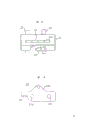
Fig. 1 is a cutaway view;
Fig. 2 is the amplification view of paper feeding device;
Fig. 3 is the amplification view that draws the paper position;
Fig. 4 is the vertical view of draw-gear;
Fig. 5 is the front view of the base plate of assembling draw-gear;
Fig. 6 is the front view of train mechanism.
With reference to Fig. 1, see Fig. 6 at two side plate 1 and 1A(opposite one another that constitute the printing device framework) between, being equipped with can be with respect to the platen (2) of its 2a rotation.Print head 3 is equipped with in the place on platen (2) opposite.Print head 3 is installed in can be on the balladeur train 4 of two axis of guides 5 and 6 horizontal back and forth movements.Ribbon cartridge 7 is counted the back that print head 3 is arranged certainly.As we all know, the device that drives balladeur train 4 is made up of fixed component 4a, and fixed component is whole on balladeur train to be formed and stretch out, and is connected with endless-belt 8, and belt 8 is seen Fig. 6 by carriage motor 9() driving pulley 10 of rotation drives.
Record-paper is imported in the space between platen 2 and the print head 3 and carries out lettering.
Hereinafter introduce record-paper is supplied to the paper feeding mouth of print position and the guide channel that record-paper is imported print position.
Sheet-fed paper feeding mouth is placed on the front (left-hand side among Fig. 1) of the outer container shell of printing device, has formed two vertical heights that comprise A and B.The carton (not shown) that holds sheet-fed is placed on this paper feeding mouth so that sheet-fed is provided.
On the other hand, feeding under the situation of continuous paper, using two paper feeding mouths, comprising paper feeding mouth C that is configured in sheet-fed paper feeding mouth B below and the paper feeding mouth D that is configured in the top of rear side (right-hand side among Fig. 1).
The purpose that sheet-fed and continuous paper are provided with two paper feeding mouths respectively is to be convenient to change the size of recording paper.
Introduce below from the guide frame of paper feeding mouth A, B and C importing record-paper.Guide channel is made of support plate 11 and guide plate 12a, 12b, 12c, 12d.Another guide channel is made of the guide plate 12e that is configured in apart from support plate 11 certain distances from paper feeding mouth D.
When manually feeding sheet-fed, can use paper feeding mouth A and arrangement and use ways 13.
Describe the structure of the drive unit that feeds continuous paper that is configured in platen 2 upstreams below with reference to Fig. 1 and Fig. 2, Fig. 2 is the enlarged drawing of major part.
The installing plate that stretches out 14 of fixed axis 15 is equipped with at the back side of support plate 11, and mobilizable lever 16 is installed on the axle 15.Axle support slot 11a and support plate are integral formation.The axle 17a of pinch roll 17 is removable and insert rotationally in the axle support slot.Make the bottom of lever 16 and axle 17a, the Elastic Contact of pinch roll 17.The spring force of realizing Elastic Contact is to be applied by the spring 18 that is installed in lever 16 top ends.Pinch roll 17 passes the hole on the support plate 11 and stretches into guide channel, again with driven roller 19 Elastic Contact so that paper feeding.Driven roller is fixed on the power transmission shaft 19a, thereby is driven.
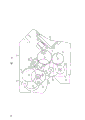
Below with reference to Fig. 1 and Fig. 3, be described in the mechanism of paper that draws of position E drawing sheet-fed (being continuous paper sometimes), record-paper is drawn in the downstream of platen 2 from position E, and Fig. 3 is the amplification view of its major part.
The driven roller 20 that draws paper to use rotates by its 20a.Make pinch roll 21 and driven roller 20 Elastic Contact, thereby record-paper to be printed utilizes the combination of these two rollers and is drawn in.Pinch roll should be configured to and can contact with driven roller, can move apart driven roller again.
That is to say, pinch roll 21 is constituted parts, and wherein the rotating shaft 21a of pinch roll is bearing on the support plate 22, and support plate 22 is equipped with the axis of guide by rotating mode, the axle of pinion 23 for example, this pinion is configured in the pilot hole 24 that is opened on the side plate.A medial surface of pilot hole 24 is equipped with tooth bar 24a, and pinion is meshed with it.Therefore, when pinion 23 makes progress in pilot hole 24 with tooth bar 24a engagement when mobile, support plate 22 also moves up.Its result, pinch roll 21 moves apart the surface of driven roller 20.
Another piece side plate also is equipped with another pinch roll parts of said structure on the relevant position.In pilot hole 24, be formed with tooth bar 24a so that pinion 23 move horizontally uniformity.The inner surface of pilot hole 24 is formed with recess 24b on the position, opposite of tooth bar 24a, make its top up to pilot hole 24 so that help manually to promote support plate, and makes axle 21a and the recess engagement of pinch roll 21, so as under to keep meshing Ribbon Change more.
The way that to remove mutually with the pinch roll 21 of driven roller 20 Elastic Contact is, will be assemblied in rotationally on the side plate 1 by axle 25a to contact with the ledge of support plate 22 in order to the trip lever 25 that discharges pinch roll, and support plate is moved.The mobile of trip lever is to carry out with the rotational synchronization of draw-gear T, hereinafter will describe in detail.
Draw-gear T is placed on paper feeding position F to supply with continuous paper.In this case, feed continuous paper with paper feeding mouth D.On the other hand, draw-gear T can be reversed to drawing paper position E so that the drawing continuous paper.Draw-gear T is at paper feeding position F and draw migration between the E of paper position and the structure of draw-gear hereinafter will be narrated.
The base plate 27(that draw-gear T is installed sees Fig. 5) ledge 27a support in rotating mode by the axle 26 that is located on the side plate 1.
Shown in the solid line among Fig. 3, be positioned at the draw-gear T of the paper feeding position F of continuous paper, by hold its base plate 27 wrench 27b, and counterclockwise rotate around axle 26, just can move along gathering sill 1a.Its result just can be placed on draw-gear T drawing on the E of paper position shown in the chain-dotted line of Fig. 3.
The result of draw-gear T reversing, rotate trip lever 25 in the bight of base plate 27 around its 25a clockwise direction.Therefore, support plate 22 is moved up along pilot hole 24, removed the elasticity connection status between pinch roll 21 and the driven roller 20 like this.
Below with reference to Fig. 6 train mechanism is described.
Gear 34 and gear 40 engagements, pinion 40a on the gear 40 and gear 41 engagements.
When draw-gear T is placed on paper feeding mouth D(is paper feeding position F) time, can make driven wheel 42 engagements of pinion 40a and draw-gear T.When draw-gear T is made to when drawing paper position E, make gear 41 and driven wheel 42 engagements.
The following describes operation of the present invention.
When from paper feeding mouth D supply continuous paper, draw-gear T is placed on the F of paper feeding position.Therefore continuous paper is fed by draw-gear, when by platen 2 and print head 3 by lettering, again by paper feeding driven roller 20 and pinch roll 21 drawings.
When to the sheet-fed lettering, can utilize paper feeding mouth A and B.Utilized driven roller 20 and pinch roll 21 drawings by the sheet-fed behind the lettering.At this moment, draw-gear T is placed on paper feeding position F, continuous paper is waited for by drawing to the anterior locations of platen 2.
The following describes the situation that feeds continuous paper by paper feeding mouth C.
Shown in the solid line among Fig. 3, be positioned at the draw-gear T of paper feeding position F, be the center with axle 26, reversed and drawn paper position E shown in the chain-dotted line to this drawing.Like this, draw-gear T is arranged on and draws paper position E.As previously mentioned, the upside-down motion of pinch roll and draw-gear T is synchronously moved apart driven roller 20.
By the continuous paper of paper feeding mouth C drawing, between platen 2 and print head, between the driven roller 20 and pinch roll 21 removed mutually, be inserted into again and be positioned at the draw-gear T that draws paper position E.In the time of the beginning lettering, continuous paper is by the draw-gear drawing.
The present invention has following effect.
Device of the present invention has above-mentioned structure, and therefore, draw-gear not only can be used for feeding continuous paper, also can be used for drawing paper. And, because sheet-fed and continuous paper can be placed on same It is compact that pulling device, the size of printing device can become. In addition, when to the sheet-fed lettering, and will be placed on the drawing position such as special arrangements such as row's page or leaf mechanisms the time, draw-gear can be reversed, move to the paper feeding position from drawing the paper position. And when utilizing draw-gear drawing continuous paper, pinch roll can be moved apart driven roller, in order to draw paper. Its result helps the setting of continuous paper on draw-gear.
Claims (2)
1, a kind of paper tractor mechanism of printing device, described printing device comprises a rotating platen (2) and a print head (3), and they are opposite each other, define the lettering zone, when printing device is worked, continuous paper can feed or pull out to conversion, by this lettering zone, Paper tractor device (1) in the described paper tractor mechanism, can change for the paper feeding position (F) and proceed to the lettering zone pulls out paper from print position draw between the paper position (E) on paper one, it is characterized in that this paper tractor mechanism also comprises a supporting arrangement (27,28,29), in order to carry Paper tractor device (T), and be rotatably supported on the pivot (26), so that with Paper tractor device (T) at paper feeding position (F) with draw between the paper position (E) and to rotate 180 °, when Paper tractor device (T) is in paper feeding position (F) as the pushing-type draw-gear, row's paper passage and paper feeding passage are parallel to each other basically, certain spacing distance is arranged mutually, when Paper tractor device (T) is in as pull-type draw-gear when drawing paper position (E), the row paper passage of its row's paper passage with as the pushing-type draw-gear time is identical.
2, paper tractor mechanism according to claim 1 is characterized in that as the pushing-type draw-gear time, and the distance between row paper passage and the paper feeding passage is basically corresponding to the diameter of platen (2).
Applications Claiming Priority (2)
| Application Number | Priority Date | Filing Date | Title |
|---|---|---|---|
| JP47060/87 | 1987-03-02 | ||
| JP62047060A JP2724457B2 (en) | 1987-03-02 | 1987-03-02 | Printer paper transport device |
Publications (2)
| Publication Number | Publication Date |
|---|---|
| CN88101160A CN88101160A (en) | 1988-09-14 |
| CN1016410B true CN1016410B (en) | 1992-04-29 |
Family
ID=12764608
Family Applications (1)
| Application Number | Title | Priority Date | Filing Date |
|---|---|---|---|
| CN88101160A Expired CN1016410B (en) | 1987-03-02 | 1988-03-02 | Paper tractor mechanism |
Country Status (9)
| Country | Link |
|---|---|
| US (1) | US5100251A (en) |
| JP (1) | JP2724457B2 (en) |
| KR (1) | KR930000182B1 (en) |
| CN (1) | CN1016410B (en) |
| DE (1) | DE3844693C2 (en) |
| GB (1) | GB2202209B (en) |
| HK (1) | HK8693A (en) |
| MX (1) | MX168656B (en) |
| SG (1) | SG115592G (en) |
Families Citing this family (11)
| Publication number | Priority date | Publication date | Assignee | Title |
|---|---|---|---|---|
| JP2524781Y2 (en) * | 1988-08-05 | 1997-02-05 | アルプス電気株式会社 | Paper feed roller structure in printer |
| JP2943314B2 (en) * | 1989-11-09 | 1999-08-30 | セイコーエプソン株式会社 | Printer mechanism and controller |
| DE4042486C2 (en) * | 1990-08-31 | 1994-10-06 | Data Techno Gmbh | Thermal printer e.g. for bus ID card |
| EP0620118B1 (en) * | 1993-03-24 | 1997-11-19 | Seiko Precision Inc. | Printer having continuous sheet supply mechanism and cut sheet supply mechanism |
| EP0671277B1 (en) * | 1994-03-11 | 1998-08-26 | COMPUPRINT S.p.A. | Printer with multifunctional paper handling capability |
| CN1058661C (en) * | 1994-10-06 | 2000-11-22 | 株式会社Pfu | Paper feed method and apparatus for printers |
| DE69511524T2 (en) * | 1994-12-02 | 2000-02-17 | Seiko Epson Corp | MECHANISM FOR RELEASING A PRINT HEAD |
| US5669724A (en) * | 1995-05-16 | 1997-09-23 | Brother Kogyo Kabushiki Kaisha | Simplified paper passage in a printer |
| DE19709941A1 (en) * | 1997-03-11 | 1998-09-17 | Siemens Nixdorf Inf Syst | Printer for printing single sheets and continuous paper webs |
| CN101214760B (en) * | 2007-12-27 | 2010-05-19 | 江门江裕映美信息科技有限公司 | Device capable of automatically switching continuous medium and single medium of printer |
| JP6107506B2 (en) * | 2013-07-25 | 2017-04-05 | セイコーエプソン株式会社 | Feed guide device and printing device |
Family Cites Families (18)
| Publication number | Priority date | Publication date | Assignee | Title |
|---|---|---|---|---|
| US4160606A (en) * | 1974-09-27 | 1979-07-10 | Honeywell Information Systems Italia | Paper feed mechanism for multiple copy printer |
| JPS6015471B2 (en) * | 1980-07-10 | 1985-04-19 | ブラザー工業株式会社 | paper feeding device |
| DE3036642A1 (en) * | 1980-09-29 | 1982-05-13 | Philips Patentverwaltung Gmbh, 2000 Hamburg | TRANSPORT DEVICE FOR PAPER RAILS IN BOOKING MACHINES |
| DE3214549C2 (en) * | 1982-04-20 | 1985-01-17 | Siemens AG, 1000 Berlin und 8000 München | Transport device for folding paper with punched edges and for roll paper |
| DE3226510C2 (en) * | 1982-07-15 | 1984-07-12 | Siemens AG, 1000 Berlin und 8000 München | Universal paper transport device for single sheets and continuous paper in line printing devices |
| EP0099958B1 (en) * | 1982-07-29 | 1986-04-30 | MANNESMANN Aktiengesellschaft | Apparatus for feeding record carriers to printers, in particular matrix printers |
| JPS5941543U (en) * | 1982-09-11 | 1984-03-17 | 株式会社ピーエフユー | Continuous slip feeding device |
| JPS6083868A (en) * | 1983-10-17 | 1985-05-13 | Nec Corp | Printer |
| US4663722A (en) * | 1983-11-26 | 1987-05-05 | Tokyo Electric Co., Ltd. | Automatic paper feed control apparatus for a printing device |
| JPS60161175A (en) * | 1984-01-31 | 1985-08-22 | Tokyo Electric Co Ltd | Paper feeder for printer |
| JPS60172567A (en) * | 1984-02-20 | 1985-09-06 | Canon Electronics Inc | Paper feed apparatus |
| JPS60145048U (en) * | 1984-03-07 | 1985-09-26 | アルプス電気株式会社 | printer paper feeder |
| JPS6163464A (en) * | 1984-09-06 | 1986-04-01 | Oki Electric Ind Co Ltd | Paper feed apparatus |
| IT1196758B (en) * | 1984-11-19 | 1988-11-25 | Olivetti & Co Spa | PRINT SUPPORT FEEDER FOR A WRITING MACHINE OR SIMILAR OFFICE MACHINES |
| JPS61105157U (en) * | 1984-12-14 | 1986-07-04 | ||
| DE3571956D1 (en) * | 1984-12-14 | 1989-09-07 | Tokyo Electric Co Ltd | Paper feed device for a printer |
| JPS61220873A (en) * | 1985-03-27 | 1986-10-01 | Canon Inc | Recorder |
| JPS62233275A (en) * | 1986-04-03 | 1987-10-13 | Seiko Epson Corp | Paper-feeding mechanism |
-
1987
- 1987-03-02 JP JP62047060A patent/JP2724457B2/en not_active Expired - Fee Related
-
1988
- 1988-03-01 GB GB8804829A patent/GB2202209B/en not_active Expired - Lifetime
- 1988-03-01 DE DE3844693A patent/DE3844693C2/de not_active Expired - Lifetime
- 1988-03-02 CN CN88101160A patent/CN1016410B/en not_active Expired
- 1988-03-02 US US07/162,890 patent/US5100251A/en not_active Expired - Lifetime
- 1988-03-02 KR KR1019880002158A patent/KR930000182B1/en not_active IP Right Cessation
- 1988-03-02 MX MX010616A patent/MX168656B/en unknown
-
1992
- 1992-11-04 SG SG1155/92A patent/SG115592G/en unknown
-
1993
- 1993-02-04 HK HK86/93A patent/HK8693A/en not_active IP Right Cessation
Also Published As
| Publication number | Publication date |
|---|---|
| JPS63212572A (en) | 1988-09-05 |
| DE3844693C2 (en) | 1992-01-09 |
| GB2202209A (en) | 1988-09-21 |
| JP2724457B2 (en) | 1998-03-09 |
| GB2202209B (en) | 1990-10-10 |
| MX168656B (en) | 1993-06-02 |
| KR880010911A (en) | 1988-10-25 |
| SG115592G (en) | 1993-01-29 |
| GB8804829D0 (en) | 1988-03-30 |
| CN88101160A (en) | 1988-09-14 |
| US5100251A (en) | 1992-03-31 |
| KR930000182B1 (en) | 1993-01-11 |
| HK8693A (en) | 1993-02-12 |
Similar Documents
| Publication | Publication Date | Title |
|---|---|---|
| CN1016410B (en) | Paper tractor mechanism | |
| CA1221993A (en) | Apparatus for supplying sheets to a line printer | |
| US4391542A (en) | Device for the stepwise feed of printing media in an electromechanical print unit | |
| US3753483A (en) | Typewriter dual feed apparatus | |
| CN1153676C (en) | Paper reversing apparatus of printer for printing both sides of paper | |
| CN102205739A (en) | Label separator and label printer incorporating the label separator | |
| CN1835847A (en) | Printer with a pivoting gear mechanism | |
| US4058196A (en) | Printer with interchangeable paper-feed modules | |
| CN88101158A (en) | Supply the device of record-paper forward and backward | |
| EP0380285A2 (en) | Sheet feed device for use in a printer or the like | |
| KR960000969B1 (en) | Transfer printer | |
| KR960000967B1 (en) | Transfer printer | |
| CN216885910U (en) | Carbon belt structure with bidirectional driving function | |
| CN1113749C (en) | Device for feeding recordable paper in ink jet printer | |
| US5069564A (en) | Printing system | |
| JP2750427B2 (en) | Paper tractor mechanism | |
| JPS6189066A (en) | Paper treater for printer | |
| EP0359579B1 (en) | Apparatus for feeding media | |
| JPS61145048A (en) | Device for detaching or feeding recording carrier for typewriter | |
| KR950008988B1 (en) | Printer | |
| JP4105317B2 (en) | Tag printer | |
| JP3677115B2 (en) | Ribbon feeder in printer | |
| US956807A (en) | Plate-printing machine. | |
| CN1362916A (en) | Printer | |
| JP2530949Y2 (en) | Automatic paper feeder |
Legal Events
| Date | Code | Title | Description |
|---|---|---|---|
| C06 | Publication | ||
| PB01 | Publication | ||
| C10 | Entry into substantive examination | ||
| SE01 | Entry into force of request for substantive examination | ||
| C13 | Decision | ||
| GR02 | Examined patent application | ||
| C14 | Grant of patent or utility model | ||
| GR01 | Patent grant | ||
| C53 | Correction of patent for invention or patent application | ||
| COR | Change of bibliographic data |
Free format text: CORRECT: PATENTEE; FROM: SEIKOSHA CO., LTD. TO: SEIKO PRECISION KK |
|
| CP01 | Change in the name or title of a patent holder |
Patentee after: Seiko Precision Inc. Patentee before: Seikosha Co., Ltd. |
|
| C15 | Extension of patent right duration from 15 to 20 years for appl. with date before 31.12.1992 and still valid on 11.12.2001 (patent law change 1993) | ||
| OR01 | Other related matters | ||
| C19 | Lapse of patent right due to non-payment of the annual fee | ||
| CF01 | Termination of patent right due to non-payment of annual fee |