CN101616632A - Method of making an oscillating tip surgical saw blade - Google Patents
Method of making an oscillating tip surgical saw blade Download PDFInfo
- Publication number
- CN101616632A CN101616632A CN200780039072A CN200780039072A CN101616632A CN 101616632 A CN101616632 A CN 101616632A CN 200780039072 A CN200780039072 A CN 200780039072A CN 200780039072 A CN200780039072 A CN 200780039072A CN 101616632 A CN101616632 A CN 101616632A
- Authority
- CN
- China
- Prior art keywords
- plate
- saw blade
- assembly
- projection
- sagitta
- Prior art date
- Legal status (The legal status is an assumption and is not a legal conclusion. Google has not performed a legal analysis and makes no representation as to the accuracy of the status listed.)
- Pending
Links
Images


Classifications
-
- A—HUMAN NECESSITIES
- A61—MEDICAL OR VETERINARY SCIENCE; HYGIENE
- A61B—DIAGNOSIS; SURGERY; IDENTIFICATION
- A61B17/00—Surgical instruments, devices or methods
- A61B17/14—Surgical saws
- A61B17/142—Surgical saws with reciprocating saw blades, e.g. with cutting edges at the distal end of the saw blades
-
- A—HUMAN NECESSITIES
- A61—MEDICAL OR VETERINARY SCIENCE; HYGIENE
- A61B—DIAGNOSIS; SURGERY; IDENTIFICATION
- A61B17/00—Surgical instruments, devices or methods
- A61B2017/00526—Methods of manufacturing
-
- Y—GENERAL TAGGING OF NEW TECHNOLOGICAL DEVELOPMENTS; GENERAL TAGGING OF CROSS-SECTIONAL TECHNOLOGIES SPANNING OVER SEVERAL SECTIONS OF THE IPC; TECHNICAL SUBJECTS COVERED BY FORMER USPC CROSS-REFERENCE ART COLLECTIONS [XRACs] AND DIGESTS
- Y10—TECHNICAL SUBJECTS COVERED BY FORMER USPC
- Y10T—TECHNICAL SUBJECTS COVERED BY FORMER US CLASSIFICATION
- Y10T29/00—Metal working
- Y10T29/49—Method of mechanical manufacture
- Y10T29/49826—Assembling or joining
Landscapes
- Health & Medical Sciences (AREA)
- Surgery (AREA)
- Life Sciences & Earth Sciences (AREA)
- Heart & Thoracic Surgery (AREA)
- Nuclear Medicine, Radiotherapy & Molecular Imaging (AREA)
- Oral & Maxillofacial Surgery (AREA)
- Engineering & Computer Science (AREA)
- Biomedical Technology (AREA)
- Dentistry (AREA)
- Medical Informatics (AREA)
- Molecular Biology (AREA)
- Animal Behavior & Ethology (AREA)
- General Health & Medical Sciences (AREA)
- Public Health (AREA)
- Veterinary Medicine (AREA)
- Surgical Instruments (AREA)
Abstract
Description
技术领域 technical field
[0001].本发明涉及制造具有静止锯条棒和相对该锯条棒枢转的头部的外科锯条的方法。[0001]. The present invention relates to a method of making a surgical saw blade having a stationary saw bar and a head that pivots relative to the saw bar.
背景技术 Background technique
[0002].弧矢状锯条是具有头部的外科锯,该头部围绕垂直于锯条的轴线枢转。在2006年8月16日申请的美国专利公开号为No.US2007/0119055A1、名称为“SURGICAL SAGITTAL SAW WITH INDEXING HEAD AND TOOLLESSBLADE COUPLING ASSEMBLY FOR ACTUATING AN OSCILLATING TIP SAW BLADEAND OSCILLATING TIP SAW BLADE WITH SELF CLEANING HEAD”的美国专利申请在此被并入以作参考,公开了包括静止锯条棒和锯条头的外科锯条组件。锯条棒是可释放地安装到机头的细长组件,该机头用于驱动该组件。该锯条头枢转地安装到具有从锯条棒向前延伸的齿的锯条棒。一个或多个驱动连杆从锯条头向这些齿延伸。机头内的驱动组件使驱动连杆来回往复运动。驱动连杆的轮流往复运动导致锯条头来回枢转。锯条头枢转使得这些齿切割锯条头按压的组织。一般地,这类锯条即振荡尖端锯条。[0002]. A sagittal blade is a surgical saw with a head that pivots about an axis perpendicular to the blade. The U.S. Patent Publication No. US2007/0119055A1, which was applied for on August 16, 2006, is named "SURGICAL SAGITTAL SAW WITH INDEXING HEAD AND TOOLLESSBLADE COUPLING ASSEMBLY FOR ACTUATING AN OSCILLATING TIP SAW BLADEAND AN OSCILLATING SAW WITH INDEXING HEAD AND TOOLLESSBLADE COUPLING ASSEMBLY FOR ACTUATING AN OSCILLATING TIP SAW BLADEAND AN OSCILLATING SAW WITH INDEXING HEAD AND TOOLLESSBLADE COUPLING ASSEMBLY FOR ACTUATING AN OSCILLATING TIP SAW BLADEAND AN OSCILLATING SAW INDEXING LE TIP SAWWI BLA" US Patent Application, incorporated herein by reference, discloses a surgical blade assembly including a stationary blade bar and a blade head. The saw bar is an elongated assembly releasably mounted to the handpiece for driving the assembly. The saw head is pivotally mounted to a saw bar having teeth extending forwardly from the saw bar. One or more drive links extend from the blade head to the teeth. A drive assembly within the nose reciprocates the drive link back and forth. The alternating reciprocating motion of the drive linkage causes the blade head to pivot back and forth. The saw head pivots so that the teeth cut tissue pressed against by the saw head. Typically, such saw blades are oscillating tip saw blades.
[0003].振荡尖端锯条的优势是,锯条中唯一枢转的部分是位于远端的锯条头。与传统的从安装到互补机头的点处枢转的弧矢状锯条相比,该锯条组件当被驱动时在外科医生握持机头的手中振动较小。同样,常规的实践是使用切割导向器以相对锯条要切割的组织而正确放置弧矢状锯条。当驱动传统的锯条时,锯条的振荡运动在切割导向器的表面上强加磨损,该导向器限定锯条坐落的缝。振荡尖端锯条的锯条棒只在该缝中最小地运动。因而,通过使用振荡尖端锯条,形成切割导向器的材料非常少(如果有的话)地变得磨损。这降低了外科医生必须冲刷从手术地点磨损的切割导向器材料的程度。进一步,振荡尖端锯条的使用减少了形成导向器的材料变得磨损以致导向器自身变得无用的程度。[0003]. The advantage of an oscillating tip blade is that the only part of the blade that pivots is the blade head at the distal end. The blade assembly, when driven, vibrates less in the surgeon's hand holding the handpiece than a conventional sagittal saw blade that pivots from a point of attachment to a complementary handpiece. Also, it is common practice to use a cutting guide to properly position a sagittal saw blade relative to the tissue the blade is intended to cut. When driving a conventional saw blade, the oscillating motion of the blade imposes wear on the surface of the cutting guide that defines the slot in which the blade sits. The saw bar of the oscillating tip saw blade moves only minimally in this gap. Thus, by using an oscillating tip saw blade, very little, if any, of the material forming the cutting guide becomes worn. This reduces the extent to which the surgeon must flush the cutting guide material worn away from the surgical site. Further, the use of an oscillating tip saw blade reduces the extent to which the material forming the guide becomes so worn that the guide itself becomes useless.
[0004].上述锯条组件的一个重要部件是枢转突起。枢转突起是锯条棒内的圆柱形静止件,锯条头按压且围绕该锯条棒枢转。锯条突起的外表面(锯条头所靠的表面)必须尽可能地光滑。这是因为表面粗糙点将会导致集中在这些点和靠着这些表面的锯条头的互补表面周围的磨损。该磨损能引起这些部件中一方或双方的失效。即使该磨损不引起结构的失效,也将导致产生可观的摩擦引起的发热。[0004]. An important part of the above saw blade assembly is the pivot protrusion. The pivot protrusion is a cylindrical stationary piece within the saw blade bar against which the saw blade head presses and pivots. The outer surface of the blade protrusion (the surface that the blade head rests on) must be as smooth as possible. This is because surface roughness points will cause wear centered on these points and around complementary surfaces of the blade head against these surfaces. This wear can cause failure of one or both of these components. Even if this wear does not cause structural failure, it will result in considerable friction-induced heating.
[0005].通过加工工件可以形成锯条棒。在加工中,形成工件的材料被选择性的移除以形成具有期望的几何特征包括枢转突起的锯条棒。使用该过程形成锯条棒太昂贵以致提供振荡尖端锯条在经济上是不能实施的。[0005]. The saw blade can be formed by machining the workpiece. In machining, material forming the workpiece is selectively removed to form a saw bar with desired geometric features, including pivoting protrusions. Forming saw blade bars using this process is so expensive that it is not economically feasible to provide an oscillating tip saw blade.
[006].进一步地,通常由相对的上下板形成振荡尖端锯条的锯条棒。锯条头和驱动杆夹在这些板之间。一旦这些部件装配在一起,相对的板固定在一起以完成振荡尖端锯条的装配。在此过程中必须小心以确保尽可能直地快速加工锯条棒。如果锯条棒具有任意曲率,当按压欲切割的组织时,锯条可以弯曲、切片。锯条这样的弯曲能反过来导致锯条沿着偏离欲切割路径的路径而切割该组织。该弯曲潜在地能大到负面影响锯条行进的能力,该锯条在插入的带缝的切割导向器中行进。[006]. Further, the saw blade bar of the oscillating tip saw blade is usually formed by opposing upper and lower plates. The blade head and drive bar are sandwiched between these plates. Once these components are assembled, the opposing plates are secured together to complete the assembly of the oscillating tip saw blade. Care must be taken during this process to ensure that the saw bar is machined as straight as possible and quickly. If the saw bar has any curvature, the saw blade can bend and slice when pressed against the tissue to be cut. Such bending of the blade can in turn cause the blade to cut the tissue along a path that deviates from the intended path of cutting. This bending can potentially be so great as to negatively affect the ability of the saw blade to travel within the inserted slotted cutting guide.
发明内容 Contents of the invention
[0007].本发明涉及制造振荡尖端锯条的新颖有效的方法。在本发明的一个过程中,锯条棒枢转突起逐渐形成在一个板中,形成枢转突起。然后,形成锯条棒的板以选择的模式焊接以充分地消除板由于焊接过程的变形。[0007]. The present invention relates to a novel and efficient method of manufacturing oscillating tip saw blades. In one process of the invention, the saw blade bar pivot protrusion is gradually formed in one plate, forming the pivot protrusion. The plates forming the saw blade bar are then welded in a selected pattern to substantially eliminate deformation of the plates due to the welding process.
[0008].在本发明的一个过程中,形成枢转突起的第一步骤包括在待形成枢转突起的板中冲压形成相对深的子弹形状节点。然后,在一系列附加的顺序冲压步骤中,加宽该节点以提供给该节点一圆柱形外轮廓。在后面的冲压过程中逐渐平坦节点头以产生最终期望的枢转突起。[0008]. In one process of the present invention, the first step of forming the pivot protrusion includes stamping a relatively deep bullet-shaped node in the plate on which the pivot protrusion is to be formed. Then, in a series of additional sequential stamping steps, the node is widened to provide the node with a cylindrical outer profile. The nodal head is gradually flattened in a subsequent stamping process to produce the final desired pivot protrusion.
[0009].上述过程产生具有圆柱几何形状的枢转突起,且并不过分损坏形成该几何形状的棒材料的表面光洁度。[0009]. The above process produces a pivoting protrusion having a cylindrical geometry without unduly damaging the surface finish of the rod material forming the geometry.
[0010].一旦锯条头和驱动杆夹在形成锯条棒的板之间,该板焊接在一起。更特别地该板使用激光焊接工艺焊接在一起。在此工艺中抵靠第二板的第一板中的角撑板穿透焊接至第二板。然后板的外周边焊接在一起。每一焊接过程包括许多分离的焊接步骤。在各个焊接步骤中,板的部分进行紧密间隔的点焊。各个部分相互分开。因而,在相邻的板的一个部分之间的焊接完成后,下一个焊接发生部分与初始部分分开。[0010]. Once the blade head and drive bar are sandwiched between the plates forming the blade bar, the plates are welded together. More particularly the plates are welded together using a laser welding process. The gussets in the first panel against the second panel are penetration welded to the second panel in this process. The outer perimeters of the plates are then welded together. Each welding process includes many separate welding steps. During each welding step, sections of the plate are welded in closely spaced spot welds. The various parts are separated from each other. Thus, after the welding between one part of the adjacent plate is completed, the part where the next welding occurs is separated from the initial part.
[0011].上述焊接过程最小化了任一各个形成棒的板的部分被加热的程度。这减少了形成板的材料的变形。该变形的减少同样最小化了锯条棒在形成过程中变弯曲的程度。[0011]. The welding process described above minimizes the extent to which any portion of each of the plates forming the rod is heated. This reduces deformation of the material forming the panel. This reduction in deformation also minimizes the extent to which the blade bar becomes bent during the forming process.
附图说明 Description of drawings
[0012].本发明的上述及进一步特征和优点从以下参照附图的详细描述而理解:[0012]. The above and further features and advantages of the present invention are understood from the following detailed description with reference to the accompanying drawings:
[0013].图1是本发明的振荡尖端锯条安装到机头上的透视图。[0013]. Fig. 1 is a perspective view of the oscillating tip saw blade of the present invention installed on the machine head.
[0014].图2是振动尖端锯条的分解图。[0014]. Fig. 2 is an exploded view of the vibrating tip saw blade.
[0015].图3是问题区域的横截面放大图,如果锯条棒的枢转突起不具有圆柱形轮廓则出现该问题区域。[0015]. FIG. 3 is an enlarged cross-sectional view of a problem area that occurs if the pivoting protrusion of the saw bar does not have a cylindrical profile.
[0016].图4是用于形成根据本发明的锯条棒的压力机的图示。[0016]. FIG. 4 is an illustration of a press used to form a saw blade bar according to the present invention.
[0017].图5是第一冲头如何开始枢转突起形成过程的局部横截面侧视图。[0017]. FIG. 5 is a partial cross-sectional side view of how the first punch begins the pivoting protrusion forming process.
[0018].图6是第二冲头如何继续枢转突起形成过程的局部横截面侧视图。[0018]. FIG. 6 is a partial cross-sectional side view of how the second punch continues the pivoting protrusion forming process.
[0019].图7是第三冲头如何继续枢转突起形成过程的局部横截面侧视图。[0019]. FIG. 7 is a partial cross-sectional side view of how the third punch continues the pivoting protrusion forming process.
[0020].图8是第四冲头如何继续枢转突起形成过程的局部横截面侧视图。[0020]. FIG. 8 is a partial cross-sectional side view of how the fourth punch continues the pivoting protrusion forming process.
[0021].图9是第五冲头如何继续枢转突起形成过程的局部横截面侧视图。[0021]. FIG. 9 is a partial cross-sectional side view of how the fifth punch continues the pivoting protrusion forming process.
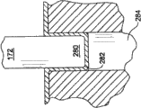
[0022].图10是第六冲头如何继续枢转突起形成过程的局部横截面侧视图。[0022]. FIG. 10 is a partial cross-sectional side view of how the sixth punch continues the pivoting protrusion forming process.
[0023].图11是第七冲头如何完成的局部横截面侧视图。[0023]. Fig. 11 is a partial cross-sectional side view of how the seventh punch is completed.
[0024].图12图示出在形成锯条棒的上下板上进行穿透焊以形成锯条棒的顺序。[0024]. FIG. 12 illustrates the sequence of performing penetration welding on the upper and lower plates forming the saw bar to form the saw bar.
[0025].图13图示出形成焊接以将上下板的相对边缘表面焊接在一起的顺序。[0025]. FIG. 13 illustrates the sequence of forming the weld to weld together the opposing edge surfaces of the upper and lower plates.
[0026].图13A是图示出在焊接之前形成锯条棒的上下板之间的间隙的横截面视图,为了图示而放大该间隙。[0026]. FIG. 13A is a cross-sectional view illustrating the gap between the upper and lower plates forming the saw blade bar prior to welding, the gap being exaggerated for illustration.
[0027].图14A是本发明中可选择的枢轴的透视图。[0027]. FIG. 14A is a perspective view of an alternative pivot in the present invention.
[0028].图14B是图示出图14A的枢轴怎样安装到锯条棒以使轴的中央头部用作锯条枢转突起的横截面视图。[0028]. FIG. 14B is a cross-sectional view illustrating how the pivot shaft of FIG. 14A is mounted to the blade bar so that the central head of the shaft acts as the blade pivot protrusion.
[0029].图15A是本发明中可选择的枢轴的透视图。[0029]. FIG. 15A is a perspective view of an alternative pivot of the present invention.
[0030].图15B是图示出图15A的枢轴怎样安装到锯条棒以使轴的中央头部用作锯条枢转突起的横截面视图。[0030]. FIG. 15B is a cross-sectional view illustrating how the pivot shaft of FIG. 15A is mounted to the blade bar so that the central head of the shaft acts as the blade pivot protrusion.
[0031].图16A是本发明可选择的锯条组件的顶部平面视图。[0031]. FIG. 16A is a top plan view of an alternative saw blade assembly of the present invention.
[0032].图16B是图16A中可选择的锯条组件的侧视图。[0032]. FIG. 16B is a side view of the alternative saw blade assembly of FIG. 16A.
[0033].图17是与图16A中的锯条组件一体的锯条头的平面视图;且[0033]. FIG. 17 is a plan view of a saw blade head integral with the saw blade assembly in FIG. 16A; and
[0034].图18是本发明两个驱动杆的远端及另一锯条组件连接支脚的平面视图。[0034]. FIG. 18 is a plan view of the distal ends of two drive rods and another blade assembly connecting foot of the present invention.
[0035].应该意识到,图示本发明机械元件的上述图应被理解为大体示出元部件各自的特征和相互之间的相对比例。标示出了为易于图示而放大其特征的图。[0035]. It should be appreciated that the above figures illustrating the mechanical elements of the present invention should be understood as generally showing the respective features of the components and their relative proportions to each other. Figures with features exaggerated for ease of illustration are labeled.
具体实施方式 Detailed ways
[0036].图1和图2图示了根据本发明而安装到机头42上的锯条组件40。锯条组件40包括可移除地安装到机头42远端的锯条棒44。(“远”指远离外科医生而朝向组件应用的手术点,“近”指朝向外科医生而远离手术点)。锯条头46放置在锯条棒44中且枢转地安装到其上。锯条头46具有位于锯条棒44之前的冠48。冠48形成有切割齿49。放置在锯条棒44中的驱动杆50从锯条头46向后朝近端延伸。驱动杆50可释放地连接至在机头内部的振荡驱动机构(驱动机构未示出且非本发明的一部分)。驱动机构驱动的结果是驱动杆50来回地往复运动。驱动杆50的往复运动导致锯条头46枢转。[0036]. FIGS. 1 and 2 illustrate a
[0037].锯条棒44分别由下、上板54和56形成。下板54具有位于近端的基部58,大致是梯形,其中相反的横向侧边缘对称且朝板54的近端边缘向内变细。下板基部58进一步形成有两个D形开口62。开口62的纵轴与下板54的纵轴对称分开且与其平行。[0037]. The
[0038].下板54在基部58之前形成有中间部64。中间部64的侧边缘随着其朝远端向前延伸而向内变细。板中间部64转变成定宽的锯条远端部66。下板54进一步形成以限定出钥匙孔形开口68,该开口从中间部62延伸至远端部66。设计开口68的尺寸以接收作为机头42的一部分的连接销70。连接销70是机头部件的一部分,其可释放地保持锯条棒44至机头。[0038] The
[0039].棒下板的远端部66的前部形成有圆形、向上延伸的突起74。在突起74的每一侧上,下板54限定了D形开口76。每个开口76纵向地与开口62的单独一个对齐。下板54也形成有两对L形补翼78。每一补翼78直接位于板54邻近的纵向侧向内。每一补翼78朝上板56向上延伸。补翼78布置成对以便每对中的每一个与该对的第二个完全相对。第一对补翼78沿着远离开口68的线定位。第二对补翼78沿着第一组补翼78和开口76之间的线定位。[0039]. The front portion of the distal portion 66 of the rod lower plate is formed with a circular, upwardly extending
[0040].在开口76之前,下板54形成有两个附加的开口,排放端口82。更特别地,排放端口82从下板表面部打开,该表面部对着锯条头基座124。每一排放端口82大约为椭圆形。下板54进一步形成以便排放端口82定中于公共的非线性纵向轴线。更特别地该轴线是弯曲的。在该轴线曲率半径的圆心中,锯条头46布置在端口下面的部分振荡。排放端口82对称地位于下板54纵向轴线周围。[0040]. Prior to the opening 76, the
[0041].下板54中也形成有两行椭圆形开口84。每行开口84位于板54一侧边缘直接向内。每行开口以直接靠近下板54的远端边缘的开口开始,且从最远端开口84向后朝近端延伸。每行开口84从邻近的排放端口82向后朝近端延伸一短距离。[0041]. The
[0042].上板56形成为与下板54大致相同的周边轮廓;不重复该轮廓的描述。上板56进一步形成有从该板边缘向下延伸的唇缘88。总体来说,设计板54和56的尺寸以便当上板56放置在下板54之上时,上板唇缘88围绕下板54的相邻边缘延伸。上板56形成以便唇缘88围绕下板54的近端和下板54纵向延伸相反的侧边缘延伸。因而,在组装时,锯条棒44具有位于下板54和上板56之间的远端开口(开口未标示出)。[0042]. The
[0043].上板56进一步形成有两个D形开口90。每一开口90形状上与每一下板开口62相同,且能够直接与其对齐位于其上。在开口90的近端后部,上板56进一步形成有向下延伸的角撑板92。在板近端的直接前方处,角撑板92横向延伸穿过上板56。两个向下延伸的小角撑板94位于角撑板92的任一侧。[0043]. The
[0044].上板56在开口90的前面形成有两个角撑板96和单个角撑板98。角撑板96围绕上板56的纵向轴线对称地定位。角撑板96位于上板56的沿着该板具有最大宽度的横向薄片部。每一角撑板96位于上板56的外周边部的直接内侧,该外周边部转变为唇缘88。角撑板96是椭圆形的。[0045].形成上板56以便角撑板98定中于该板的纵向轴线且沿着其延伸。角撑板98从相对角撑板96近端稍微近一点的位置,延伸到大致对应于下述讨论的开口104的近端。形成上板56以便邻近角撑板96的角撑板98相对宽些。(角撑板98的“宽”和“窄”指角撑板沿着它的横向轴线的宽度)。在角撑板98的近端的前部,钥匙孔形开口102形成在角撑板98中。开口102与下板开口68尺寸相同且能够与开口68对齐。从开口102远远向前,形成上板56以便角撑板98具有较窄的恒定宽度。[0044] The
[0046].一对附加的D形开口104延伸穿过上板56的远端。每一开口104具有相同的形状且与互补的下方下板开口76对齐。在开口104的前方,上板56进一步形成有三角形的角撑板106。角撑板106居中于顶板的纵向中心线。角撑板106进一步能在被锯条头基座124对着的表面区域内从顶板的内表面延伸。[0046]. A pair of additional D-shaped openings 104 extend through the distal end of the
[0047].上板56进一步形成有两行椭圆形开口108。每一行开口108邻近地位于上板的侧边缘。每一行开口108,如同下板开口84,从板远端向后朝近端延伸。下板开口84和上板开口108可以或不相互重叠。[0047]. The
[0048].驱动杆50分别布置于锯条棒下上板54和56之间。每一驱动杆50为细长的金属平条形状。形成驱动杆50以便在每一杆的近端处具有圆形支脚114。形成每一支脚114而具有中心定位的通孔116。设计通孔116的尺寸以便相关的驱动杆支脚114能够装配到与机头42一体的驱动销。[0048]. The drive rods 50 are respectively arranged between the lower and
[0049].应该意识到形成驱动杆50以便它们的支脚114比细长的中央主体更厚。在本发明的一些变形中,驱动杆50的基本厚度大约是0.38mm(0.015英寸);围绕孔116的加强环使杆的该部件具有大约1.14mm(0.045英寸)的厚度。在本发明的一些变形中,通过形成驱动杆的工件的选择性研磨,成形驱动杆50。[0049]. It should be appreciated that the drive rods 50 are formed so that their legs 114 are thicker than the elongated central body. In some variations of the invention, the basic thickness of the drive rod 50 is about 0.38 mm (0.015 inches); the reinforcement ring around the hole 116 gives this part of the rod a thickness of about 1.14 mm (0.045 inches). In some variations of the invention, the drive rod 50 is shaped by selective grinding of the workpiece forming the drive rod.
[0050].锯条头46具有为锯条头一部分的基座124,冠48从该部分延伸。锯条头分别坐落于上下板54、56之间的间隙中。在本发明的一个变形中,锯条头基座具有大约为0.025mm(0.001英寸)的厚度,该厚度小于在上下板各自的相对面之间的间隙宽度。形成锯条头基座124以便具有近端部126和邻近的远端部128。虽然未标识,能够看到从近端部126的近端向前延伸,锯条基座的侧边缘向内变细。锯条基座远端部128具有从邻近的近端部126的窄末端向外延伸的近端。[0050] The
[0051].进一步形成锯条头基座124以便邻近的近端部126在锯条头基座124的近端处,具有一对相对的底座132。每一底座132成形为弓形。完全相对的通孔134进一步形成在锯条头基座124中,且直接位于近端的前面。每一通孔134居中于轴线,邻近的支脚132围绕该轴线居中。进一步形成锯条头基座124的远端部以便限定凹入的半圆形缺口138。缺口138沿着锯条头46的纵向轴线居中。更特别地,设计缺口138的尺寸以便当组装锯条40时,下板突起74坐落于缺口138中,且锯条头46能够围绕该突起枢转。[0051]. The saw blade base 124 is further formed so that the adjacent
[0052].锯条头基座远端部128具有两侧边缘(未标识),沿着锯条头向远端延伸且向内变细。进一步形成基座远端部128以限定通透的窗140。安置窗140以便当装配锯条40时,上板角撑板106延伸通过窗。[0052]. The blade head base distal portion 128 has two side edges (not identified) extending distally along the blade head and tapering inwardly. The base distal portion 128 is further formed to define a window 140 therethrough. The window 140 is positioned so that the upper plate gusset 106 extends through the window when the
[0053].锯条头冠48比相关的基座124的厚度更大。更特别地,形成锯条头冠48以便由冠切成的切口足够宽以允许锯条棒44插入切口。经常形成冠以便切口至少比锯条棒44的厚度大0.025mm(0.001英寸)。锯条头冠48的精确几何形状是特定切口几何形状的函数,且并非与本发明相关。[0053] The blade crown 48 is thicker than the associated base 124. More particularly, saw blade crown 48 is formed so that the cut made by the crown is sufficiently wide to allow insertion of
[0054].指状物142和销144将锯条头46枢转地保持至驱动杆50。一对指状物142从每一驱动杆50的远端表面向前延伸。指状物142与驱动杆50形成一体。研磨每一驱动杆50的表面以形成厚度小的细长体和相对宽的远端。如导线放电加工工艺的切割工艺用于形成分隔指状物的切口,锯条头基座124滑动装配在该切口中。在表面研磨工艺中,进一步形成每一驱动杆50以便限定相对厚的支脚114。[0054] The fingers 142 and pin 144 pivotally hold the
[0055].每一指状物形成有通孔146。当装配锯条40时,销144延伸通过指状物孔146和锯条基座孔134以将驱动杆50枢转地保持至锯条头46。在本发明的一些变形中,用不锈钢形成销144,例如不锈钢材料类型EN100-31.4034或400系列不锈钢。[0055]. Each finger is formed with a through hole 146. The pin 144 extends through the finger hole 146 and the blade base hole 134 to pivotally retain the drive bar 50 to the
[0056].销144经常用激光焊接工艺紧固在位置上。这是个二步工艺。在此工艺的第一步,销144一末端处的外圆形边缘激光焊接至驱动杆指状物142的邻近边缘,该指状物限定销坐落在其中的孔144。之后,在该工艺的第二步,销的相反端激光焊接至相对的指状物142的邻近边缘表面。[0056] The pins 144 are often secured in place using a laser welding process. This is a two-step process. In the first step of the process, the outer circular edge at one end of the pin 144 is laser welded to the adjacent edge of the drive rod finger 142 which defines the hole 144 in which the pin sits. Then, in a second step of the process, the opposite end of the pin is laser welded to the adjacent edge surface of the opposing finger 142 .
[0057].一旦制造了锯条头和驱动杆配件,该配件靠着上板56的内表面放置。下板54装配在上板唇缘88以内。该布置的结果是,相对厚的驱动杆支脚各自放置在下上板开口62和90中。指状物142和销144分别放置在下上板开口76和104中。[0057]. Once the blade head and drive bar assembly is manufactured, the assembly is placed against the inner surface of the
[0058].当锯条40装配至机头42时,与机头一体的驱动销及驱动杆50一起配合拉动锯条头基座124靠着锯条棒突起74。在驱动锯条40的过程中,限定缺口138的锯条头的凹入面因而靠着突起74往复地枢转。图3是如果锯条头基座124抵靠的突起74的圆周表面不是基本上的圆柱状则出现什么情况的放大图。具体地,如果由于不精确的制造方法,该突起表面远离锯条头基座124的缺口限定表面而朝近端变细。在图3中,由标识号148引出的此变细因图示目的而放大。具体地,在这种情况下锯条头基座124施加在突起74上的力分布在相对窄的区域,由标识号149引出。这意味着该区域承受可观的机械应力和摩擦导致的热。结果是,能量的这两种集中形式能够潜在地导致形成突起的材料的失效。[0058]. When the
[0059].现开始参考图4而描述制造下板54以便产生相对圆柱形的枢转突起的方法。具体在一系列冲压步骤中,枢转突起74形成在下板中。在图4中,图示出完成这些步骤的渐进金属压力机150。压力机150具有静止的下模板152。下模板152具有露出的顶面154。金属带158延伸在模板面154上,该金属带连续形成许多下板54。上冲压板160位于下模板顶面154之上。许多冲头162-174从上冲压板160悬挂且朝向下模板152。在每一冲头162-174下方,下模板152各自形成有钻孔178-190。具有冲压-钻孔对的每一地方能被认为是在压力机150上分离的冲压站。[0059]. Referring now to FIG. 4, the method of manufacturing the
[0060].金属压力机150也包括压板194。压板194在上冲压板160下面延伸且通过一组弹簧196从上冲压板悬挂。压板194形成有多个通孔197。每一冲压机162-174坐落于单独的一个压板通孔197中。[0060] The
[0061].驱动机构未示出但可明白是金属压力机150的一部分,该机构迫使上冲压板160、冲头162-174和压板194压靠在下面的模板之下的金属带158。在本发明的一些变形中,该驱动机构能迫使上冲压板160以227公吨(250英吨)和454公吨(500英吨)之间的力压靠模板。在本发明的一些变形中,该驱动机构能迫使上冲压板160以最小90公吨的力压靠模板。[0061]. The drive mechanism, not shown but understood to be part of the
[0062].安装到金属压力机150的传送机构也未示出。该传送机构以步进的模式在七个冲压站的每一个之间移动金属带158。因而,在压力机150的每一运转中,在金属带的七个不同部分上完成冲压步骤。在每一带部分进行第七个步骤后,能认为枢转突起74完全形成了。在此第七步骤后,金属带158的每一下板形成部能经受额外的压力操作。这些冲压操作与突起74的形成无关。[0062]. The transfer mechanism mounted to the
[0063].在本发明的一些优选变形中,由420不锈钢或等同的金属形成的金属带158形成下上板54和56。这样的一种金属可从瑞典Sandviken的Sandvik AB的Sandvik 7C27Mo2带钢得到。可知该材料具有化学成分(按重量):0.38%的碳、0.40%的硅、0.55%的锰、最多0.025%的磷、最多0.010%的硫、13.5%的铬、剩余为铁。金属带158的厚度为0.38mm(0.015英寸)或更少。[0063]. In some preferred variations of the invention, a
[0064].每次驱动金属压力机时,压板194压靠金属带158。压板194压缩金属带158以将金属带保持至模板顶面154。当上冲压板160持续向下移动时,每一冲头162-174延伸通过相关的压板通孔197。之后这些冲头按压金属带在冲压站处陷入并可进入的下部。之后每一冲头162-174迫使下面的金属带进入各自相关的模钻孔178-190中。金属带的此连续冲压成形导致枢转突起74形成有期望的圆柱形几何形状。[0064]. The
[0065].图5示出在第一冲压步骤中冲头162怎样开始形成枢转突起74。冲头162具有宽直径基座(未示出),剩余冲头164-174也一样。成形该基座以便利冲头在相关的压板通孔197中的紧密滑动。窄直径的细长杆204从基座向下延伸。比杆窄的头部在杆下面延伸。成形冲头162的头部以限定圆柱形柱脚208。柱脚208具有的直径小于相关的杆204的直径。在柱脚208的下面,冲压机162具有尖端210。尖端210是冲头162中撞击下面的金属带158的部分。尖端210具有子弹形轮廓。因而,尖端210具有中央表面212,该表面具有窄直径的第一曲率半径。尖端210也具有延伸在中央表面212和头部柱脚208外周之间的周边表面214。周边表面214具有的曲率半径大于中央表面212的曲率半径。虽然中央表面212和周边表面214的曲率半径不同,但是两曲面均定中心于冲头162的纵中心线上。中央表面212的曲率中心比周边表面214的曲率中心更接近于冲头162的末端。[0065]. FIG. 5 shows how the
[0066].在此冲压步骤中,冲压机162的头部驱动金属带的先前平坦的部分进入下面的模板钻孔178。因而,该步骤的结果是金属带现在具有子弹头形状的突起,以标识号217标明。[0066]. In this stamping step, the head of the
[0067].在第一和第二冲压步骤之间,形成金属带158的子弹头形突起的部分被转移到第二冲头164坐落的冲压站处。应该明白在每一冲压步骤后发生相似的转移。这些额外的转移步骤不进一步讨论。[0067]. Between the first and second stamping steps, the portion forming the bullet-shaped protrusion of the
[0068].第二到第七冲头164-174重新成形突起74以便具有设计的圆柱形。最佳地示出在图6中的第二冲头164具有杆217,圆柱形柱脚218从该杆延伸且直径小于杆217的直径。成形柱脚以具有延伸的圆尖端220。第二冲头164的柱脚218直径宽于第一冲头162的柱脚208的直径。成形尖端220以具有圆的且具有第一曲率半径的中央表面222。在中央表面222和柱脚214之间,尖端220具有周边表面224。周边表面224的曲率半径大于中央部分222的曲率半径。因而,沿着任意穿过第二冲头尖端220的侧线,中央表面222具有的曲率半径以沿着穿过冲头164的纵向轴线的一点处为中心。在尖端220的相反端处,周边表面224具有两个曲率半径,该两个曲率半径位于纵向轴线的相反侧。[0068]. The second to seventh punches 164-174 reshape the
[0069].还应该明白,第二冲头164从基座162的自由端到尖端中央部分222的相反端的总长度,短于第一冲头162的可比较的长度。在图4中这些长度的差异为图示目的而放大。因而,如图6中看到的,第二冲压步骤的结果是该突起的末端同第一步骤的形状相比较,形成圆度较小的末端,并且直接位于该末端上方的过渡部分弯曲较小、角度较大。[0069]. It should also be appreciated that the overall length of the
[0070].图7图示出第三冲头,冲头166,和因为该冲头而导致形变的突起的形状。特别地,第三冲头166具有大致圆柱形状的尖端232。尖端232的直径大于第二冲头164的柱脚218的直径。尖端232具有平面状的外表面234。在外表面234和圆柱侧壁之间,尖端232具有弯曲角部236。角部236的曲率半径小于第二冲头尖端周边表面224的曲率半径。[0070]. FIG. 7 illustrates a third punch, punch 166, and the shape of the protrusion deformed by the punch. In particular, the
[0071].第三冲头166的总长度小于第二冲头164的总长度。成形冲头166和剩余的冲头168-174以便不具有位于它们的基座和金属成形头部之间的中间杆部。[0071]. The total length of the
[0072].因此,第三冲压步骤的结果是,突起末端在形成后继续发展为更平坦的形状。突起邻接其顶部的环形部(倒转示出在图7中)也更按压为圆柱形状。进一步,形成突起的材料的向外变形的结果是突起的总高度相对于其早期形状开始减小。[0072]. Thus, as a result of the third stamping step, the protruding ends continue to develop into a flatter shape after formation. The annular portion (shown upside down in FIG. 7 ) where the protrusion adjoins its top is also more compressed into a cylindrical shape. Further, as a result of the outward deformation of the material forming the protrusions, the overall height of the protrusions begins to decrease relative to its earlier shape.
[0073].示出在图8中的第四冲头168具有尖端238,该尖端与第三冲头166的尖端232具有相同的基本几何形状。尖端238具有与尖端232相同的外径。尖端238也具有平坦外表面240。在外表面240和圆柱形周边表面之间,尖端238具有弯曲角部242。角部242具有的曲率半径小于第三冲头166的角部236的曲率半径。第四冲头168具有的总长度稍微小于第三冲头166的总长度。[0073]. The
[0074].模板钻孔184不是完全打开,在其中第四冲头按压以形成突起。钻孔184如同剩余的钻孔186、188和190装配有塞248。如示出在图4中,塞248坐落在位于模板252下方的基板250上。实际上塞248搁在垫片252上,示出单独的一个搁在基板上。垫片252被选择性地移除和替换以调节塞头部到模板顶面154的相对位置。应意识到垫片被相似地应用以将塞安放在钻孔186、188和190中。[0074] The template bore 184 is not fully open in which the fourth punch presses to form the protrusion.
[0075].塞248安放在钻孔184中以便当成形突起初始位于钻孔中时,钻孔尖端搁在塞的外露表面上。当上冲压板160下降时,压板194保持局部形成的突起靠着塞248。然后第四冲头168按压形成突起的金属的内表面。因而,突起的末端夹在塞248顶部和冲头尖端238之间。这一动作的结果是突起顶部呈现为平面形状的程度增加了。同样,突起的环形侧壁和其顶面之间的过渡呈现直角轮廓的程度增加了。[0075] The
[0076].第五冲头170具有的尖端252非常相似于第四冲头尖端238。这些尖端的外直径相同。这些尖端之间的差异是尖端252具有的角部254的曲率半径小于尖端238的角部的曲率半径(过渡更尖)。第五冲头170比第四冲头168短。塞256坐落在模压钻孔186中,冲头170插入在该钻孔中。塞256安放在钻孔186中,以便该塞的尖端、钻孔的末端比塞248的尖端更接近模板顶面。[0076] The
[0077].因而,在该冲压步骤中,冲头尖端252按压成形的突起靠着塞256。该动作进一步平坦该突起且增加突起具有圆柱形状的程度。[0077] Thus, during this stamping step, the
[0078].第六和第七冲压步骤相似于第四和第五冲压步骤。但是,第六冲头172具有的尖端280的直径稍微小于第五冲头尖端252的直径。第六冲头尖端具有的角表面282的曲率半径小于第四冲头170角表面254的曲率半径。第六冲头172的总长度小于第五冲头170的总长度。[0078]. The sixth and seventh stamping steps are similar to the fourth and fifth stamping steps. However, the
[0079].塞284坐落于模板钻孔188中,第六冲头172延伸进入该钻孔中。垫片252将塞保持在钻孔284中以便该钻孔的尖端比塞尖端更接近模板顶面154。[0079] The
[0080].第七冲压步骤是枢转突起74形成的最后过程。第七冲头174具有的尖端290的直径等于第五冲头尖端252的直径。冲头尖端290具有的角292的曲率半径等于第六冲头角表面282的曲率半径。第七冲头174稍微比第六冲头172短。[0080]. The seventh stamping step is the final process of pivoting
[0081].塞294形成在模板钻孔190中,第七冲头174延伸进入该钻孔。塞294安放在钻孔190中以便塞尖端与塞284尖端相比更接近模板顶面154。[0081] A
[0082].第七冲压步骤的结果是,枢转突起74具有直接从形成下板54的金属接近垂直地升起的外壁。枢转突起的外圆周壁本质上是圆柱形的。倒转地示出在图11中的该突起的顶部本质上是平坦的。[0082]. As a result of the seventh stamping step, the
[0083].在此过程中,形成突起的金属具有最小的表面应力。该应力的减少表明,当锯条基座被靠着枢转突起推进且围绕突起重复枢转时,这些运动的力不会导致形成突起的金属的失效。进一步,假定枢转突起对锯条基座呈现为圆柱形表面,锯条基座靠着突起的力分散到相对宽的区域。由枢转动作运动产生的热同样地被分散。该机械能和热能扩散进入枢转突起74同样地用于最小化形成突起的材料失效的可能性。[0083]. During this process, the metal forming the protrusion has minimal surface stress. This reduction in stress indicates that when the blade base is urged against and repeatedly pivoted about the pivot protrusion, the forces of these movements do not cause failure of the metal forming the protrusion. Further, given that the pivoting protrusion presents a cylindrical surface to the blade base, the force of the blade base against the protrusion is spread over a relatively wide area. Heat generated by the pivoting action movement is likewise dissipated. This diffusion of mechanical and thermal energy into the pivoting
[0084].应意识到在每一冲压步骤中,其它需要从金属带形成下板54的过程可以被执行。这些包括从带到板的全面成形、开口62、68、76和84的形成和补翼78的形成。在单独的一个步骤或多个步骤(未图示出)中,单独形成的下板54被从金属带的前端切割。[0084]. It should be appreciated that in each stamping step, other processes may be performed that require forming the
[0085].一旦形成板和形成锯条40的其它部件,这些部件被组装在一起。然后应用一系列激光焊接步骤以将下上板54和56各自固定在一起。图12和图13图示该焊接发生的顺序。在图12中的第一步“1”中,应用通过下板54的穿透焊接以将上板角撑板106的隐藏面焊接到下板54。在该焊接中,进行一系列重叠的点焊。每一焊接具有大约0.97mm(0.038英寸)的直径。各个焊接彼此大约间隔0.33mm(0.013英寸)。[0085]. Once the plate and other parts of the
[0086].在图12中的下一焊接步骤“2”中,使用一系列重叠的穿透点焊以将角撑板98位于开口102前方的一部分焊接至下板。该焊接在靠近开口102并且其前方的位置处开始,且朝向锯条棒远端前进。在此步骤中,不是整个角撑板都如此焊接至下板。相反,在步骤“3”中,下板54在角撑板远端处焊接到角撑板98。由步骤“3”形成的焊接未达到由步骤“2”形成的焊接的远端终点就停止。[0086]. In the next welding step "2" in FIG. 12, a series of overlapping penetration spot welds are used to weld the portion of the gusset 98 forward of the opening 102 to the lower plate. The weld begins at a location near and in front of the opening 102 and progresses toward the distal end of the saw blade bar. In this step, not the entire gusset is so welded to the lower plate. Instead, in step "3", the
[0087].在步骤“2”和步骤“3”的点焊过程中,这些焊接和步骤“1”具有相同的直径。但是步骤“2”和步骤“3”的焊接布置更紧密,具有大约0.20mm(0.008英寸)的分隔。[0087]. In the spot welding process of step "2" and step "3", these welds have the same diameter as step "1". But the welding arrangements of steps "2" and "3" are closer together, with a separation of about 0.20mm (0.008 inches).
[0088].在步骤“4”中,应用穿透焊接以在下板54和角撑板98的宽的近端之间形成大致U形的焊接。[0088]. In step "4", a penetration weld is applied to form a generally U-shaped weld between the
[0089].在步骤“5”中,形成环形焊接以将下板54焊接到枢转突起74的顶部周边。这再次是个穿透焊接过程。在此过程中,形成具有大约0.84mm(0.033英寸)直径的各个焊接。在此圆的360度上形成大约40个点焊以形成焊接。[0089]. In step "5", a circular weld is formed to weld the
[0090].一旦沿着锯条棒44的中央形成焊接,沿着上锯条唇缘88邻接下板54外边缘的交界处形成焊接。图13中的步骤“6”代表这些焊接的开始。该焊接在锯条棒一侧上的最远端补翼78的远端点处开始,且向前延伸至图13中开口84中的一个的一侧的点处,点290。步骤“7”在锯条棒44相反侧上形成相同的焊接。[0090]. Once the weld is formed along the center of the
[0091].一旦执行步骤“6”和步骤“7”,沿着锯条棒44侧部形成两个附加的焊接,沿着该侧部形成步骤“6”的焊接。在步骤“8”中,沿着两个补翼78之间的上板唇缘-下板的交界形成焊接。在步骤“9”中,沿着从最近端补翼78朝近端延伸的线形成焊接。[0091]. Once steps "6" and "7" are performed, two additional welds are formed along the side of the
[0092].然后,在步骤“10”中,在两板之间沿着下板基座58变细的外边缘形成短焊接。在步骤“11”中,沿着该基座形成焊接以从步骤“10”焊接的近端向后开始一短距离。在步骤“11”中,围绕在下板基座58的侧部和近端之间的曲线形成焊接。在步骤“8”、“9”、“10”和“11”的每一个中,沿着向后移动至锯条棒44的近端的路径完成焊接。[0092]. Then, in step "10", a short weld is formed between the two plates along the tapered outer edge of the lower plate base 58. In step "11", a weld is formed along the base to start a short distance back from the proximal end of the step "10" weld. In step “11 ”, a weld is formed around the curve between the side and the proximal end of the lower plate base 58 . In each of steps "8", "9", "10" and "11", the welding is done along the path moving back to the proximal end of the
[0093].在图13中一系列标记为“12”、“13”、“14”和“15”的步骤中,在锯条棒的相反侧上形成焊接。步骤“12”、“13”、“14”和“15”中的焊接分别对应步骤“8”、“9”、“10”和“11”中的焊接。[0093]. In a series of steps labeled "12", "13", "14" and "15" in FIG. 13, welds are formed on opposite sides of the saw blade bar. The welding in steps "12", "13", "14" and "15" corresponds to the welding in steps "8", "9", "10" and "11", respectively.
[0094].在步骤“8”至“15”中,重叠点焊的各个焊点具有大约0.71mm(0.028英寸)的直径。这些焊接的中心大约间隔0.32mm(0.0125英寸)。[0094]. In steps "8" to "15", each spot weld of the overlap spot weld has a diameter of approximately 0.71 mm (0.028 inches). The centers of these welds are approximately 0.32mm (0.0125 inches) apart.
[0095].在步骤“16”中,在步骤“7”中产生的焊接前方形成焊接。在步骤“16”中,该焊接形成为延伸至板54和56的远端。然后在步骤“17”中在板54和56的相反侧上形成焊接。因而步骤“17”的焊接在在步骤“6”中产生的焊接的前方延伸。在步骤“16”和“17”中形成的点焊的直径与在步骤“8”至“15”中产生的点焊的直径相同。但是,这些焊接更紧密重叠。步骤“16”和“17”的焊接之间的中心点大约间隔0.061mm(0.0024英寸)。[0095]. In step "16", a weld is formed ahead of the weld produced in step "7". In step “ 16 ”, the weld is formed to extend to the distal ends of
[0096].为了使步骤“6”至“17”的焊接具有期望的强度,下棒54的外侧边缘必须相对上棒56的唇缘88的邻接内表面紧密地定位。在这些表面之间的间隙87(图13A)应该不超过0.025mm(0.001英寸)。理想地,这些表面应该抵靠。[0096]. In order for the welds of steps "6" to "17" to have the desired strength, the outside edge of the
[0097].应意识到,可以使用其它方法装配锯条40以便枢转突起具有期望的几何形状。[0097]. It will be appreciated that other methods of assembling the
[0098].例如,与锯条棒形成的上下板分离的部件可以形成枢转突起。图14A图示出具有盘形头部302的枢轴301。两个圆柱形耳部304从头部302的相反面向外延伸。该耳部具有小于头部302直径的共同直径。如示出在图14B中,当装配锯条或本发明的该变形时,突起耳部304分别坐落在形成在下上板54和56中的分离的孔308和310中。耳部焊接至相邻的板。销头302用作锯条头46围绕枢转的圆柱件。[0098]. For example, a part separate from the upper and lower plates formed by the saw bar may form the pivoting protrusion. FIG. 14A illustrates a
[0099].在枢轴301未图示出的变形中,该枢轴具有单个耳部从其延伸的圆柱形头部。耳部坐落在下或上板54或56其中之一的通孔中。该头部的另外一侧上的平面可以穿透焊接至上下板中另一个的邻接表面。[0099]. In a variant not shown of the
[00100].可选择的,如示出在图15A中,枢轴312可以具有纺锤形状。枢轴312具有两个大直径的盘形状的耳部314。小直径的圆柱头部316在耳部314之间延伸并将其连接。如示出在图15B中,当装配具有枢轴312的锯条时,头部316用作锯条头围绕枢转的圆柱件。[00100] Optionally, as shown in Figure 15A, the
[00101].在本发明的一些变形中,锯条头围绕枢转的枢轴可以是恒定直径的圆柱销(销未图示出)。销的相反端安装在形成锯条棒的板的对齐开口中。[00101]. In some variations of the invention, the pivot about which the blade head pivots may be a constant diameter cylindrical pin (pin not shown). The opposite end of the pin fits in an aligned opening in the plate forming the saw blade bar.
[00102].示出在图16A和16B中,在本发明锯条的可选择的变形中,锯条棒44a形成有侧开口330。[00102]. Shown in FIGS. 16A and 16B, in an alternative variation of the saw blade of the present invention, the saw blade bar 44a is formed with a
[00103].在本发明的该变形中,锯条具有锯条头46a,该锯条头具有形成有补翼的基座124a。示出在图17中,补翼332从基座远端部128a的侧边缘横向向外延伸。在本发明的图示变形中,补翼332的外侧具有凹入轮廓。应意识到这是说明性的,不是限定性的。在本发明的一些变形中,补翼具有三角形轮廓。就是说,每一补翼具有从基座远端部向外变细的表面,补翼从该远端部延伸。然后在最宽的最近端位置处,补翼的边缘与远端部接触的角度等于或接近直角。仍在本发明的另一变形中,每一补翼332的外边缘是直的边缘。尽管没图示出,应意识到相似的补翼从基座近端部向外延伸。[00103]. In this variation of the invention, the saw blade has a blade head 46a with a
[00104].放置这些补翼以便当锯条头46a枢转至锯条棒44的一侧时,补翼延伸出相邻的开口330。因而,补翼用作将陷在锯条棒中的碎屑推出的犁。碎屑的排出最小化了碎屑在锯条棒中阻塞并负面影响锯条操作的可能。[00104]. The tabs are positioned so that when the saw blade head 46a is pivoted to one side of the
[00105].图17也图示了具有弓形状的锯条头冠48a。因而该冠的相反侧边缘340位于从共同的中心点伸出的间隔的径向线上。进一步形成锯条头冠48a在冠的近端处具有向外伸出的指状物342。每一指状物342从相关的侧边缘向外延伸。每一指状物大致是J形状且被定位以便指状物的钩状端在向前的方向延伸,朝向锯条齿的远端沿着其定位的范围(radius)。[00105]. FIG. 17 also illustrates a
[00106].当驱动具有锯条头冠48a的锯条时,指状物342将陷在切口中的碎屑推出冠48a的行进路径,该切口由锯条齿形成。碎屑的移动减少了碎屑降低切割效率的程度,且碎屑被向后移动以在锯条棒中被拖走。[00106]. When driving the saw blade having the
[00107].图18图示本发明锯条组件一部分的可选的构造。具体地,图18图示平面状驱动支脚350怎样连接到锯条组件驱动杆50a的近端。在本发明的该变形中,与指状物142(图2)相似的重叠的指状物352从每一驱动杆50a向后朝近端延伸。驱动支脚350具有相反的向外延伸的补翼354。每一补翼354枢转地安装到由一对重叠的驱动杆指状物352限定的槽中。[00107]. Figure 18 illustrates an alternative construction of a portion of a saw blade assembly of the present invention. Specifically, FIG. 18 illustrates how the
[00108].支脚350也具有两个相反的补翼356,这些补翼名义上沿着锯条组件的纵轴线定位。每一补翼356具有开口358。本发明的锯条组件用于安装到具有驱动头的机头,该驱动头具有名义上对齐机头纵轴线的两个驱动销。当该驱动销振荡时,它们导致支脚350进行相似的运动。该运动使驱动杆50a前后往复运动以导致期望的锯条头枢转的运动。[00108]. The
[00109].可选择地,支脚350形成有非圆形轮廓的中央孔。本发明该变形的锯条安装到具有单个驱动销的机头。驱动销具有允许销紧密滑动地安装在锯条支脚350中的互补孔中的横截面几何形状。当驱动机头时,驱动销振荡。该运动导致支脚350相似的运动。支脚350对驱动杆50a传递振荡运动以便驱动杆往复运动。[00109]. Optionally, the
[00110].因而应明白上述涉及本发明制造方法和锯条的具体特征。本发明可以从已经描述的内容而变化。[00110]. Therefore, it should be understood that the above-mentioned specific features related to the manufacturing method and saw blade of the present invention. The invention may vary from what has been described.
[00111].例如,无需在本发明的所有变形中实施通过冲压而形成枢转突起的方法和激光焊接由棒形成的上下板的方法。这些方法在合适时可以分别实施。[00111]. For example, the method of forming pivoting protrusions by stamping and the method of laser welding the upper and lower plates formed of bars need not be implemented in all variants of the present invention. These methods can be carried out separately as appropriate.
[00112].在本发明通过冲压而形成枢转突起的方法中,可以需要更多或更少的步骤形成枢转突起,以便该突起具有期望的几何形状且确保形成该突起的材料具有期望的无应力的表面光洁度。[00112]. In the method of the present invention for forming a pivoting protrusion by stamping, more or fewer steps may be required to form the pivoting protrusion so that the protrusion has the desired geometry and ensure that the material forming the protrusion has the desired Stress-free surface finish.
[00113].可以使用可选择的方法以形成枢转突起。例如,可以通过选择性刻蚀毛坯工件以形成枢转突起和板的剩余部分,该剩余部分和枢转突起是一体的。该刻蚀的结果是至少该枢转突起,不然是锯条板的其它特征,产生期望的形状。同样,在本发明的一些变形中,枢转突起的外壁可以不具有完全圆形的横截面轮廓。[00113]. Alternative methods may be used to form the pivoting protrusions. For example, the pivot protrusion and the remainder of the plate, which is integral with the pivot protrusion, may be formed by selectively etching the blank workpiece. As a result of this etching, at least the pivot protrusion, but not other features of the saw blade, take the desired shape. Also, in some variations of the invention, the outer wall of the pivot protrusion may not have a perfectly circular cross-sectional profile.
[00114].可以实施根据本发明将上下板焊接在一起的激光焊接的可选择的顺序。[00114]. An optional sequence of laser welding for welding the upper and lower plates together according to the invention may be performed.
[00115].进一步,在本发明的一些变形中,可以执行非激光焊接的过程以形成期望的焊接。因而,在本发明的一些变形中,可以一起使用电弧焊、分离电子束或电阻焊接以分别形成角撑板的中央焊接和/或上下板54和56侧的焊接。[00115]. Further, in some variations of the present invention, a process other than laser welding may be performed to form the desired weld. Thus, in some variations of the invention, arc welding, split electron beam or resistance welding may be used together to form the central weld of the gusset and/or the welds of the upper and
[00116].因此,所附权利要求的目标是覆盖在本发明的实质精神和范围内的所有这种变化和修正。[00116]. Accordingly, it is the aim of the appended claims to cover all such changes and modifications as fall within the true spirit and scope of this invention.
Claims (15)
Applications Claiming Priority (2)
| Application Number | Priority Date | Filing Date | Title |
|---|---|---|---|
| US83905106P | 2006-08-21 | 2006-08-21 | |
| US60/839,051 | 2006-08-21 |
Publications (1)
| Publication Number | Publication Date |
|---|---|
| CN101616632A true CN101616632A (en) | 2009-12-30 |
Family
ID=39031070
Family Applications (1)
| Application Number | Title | Priority Date | Filing Date |
|---|---|---|---|
| CN200780039072A Pending CN101616632A (en) | 2006-08-21 | 2007-08-20 | Method of making an oscillating tip surgical saw blade |
Country Status (9)
| Country | Link |
|---|---|
| US (2) | US8323285B2 (en) |
| EP (1) | EP2053978B1 (en) |
| JP (2) | JP2010501275A (en) |
| KR (1) | KR101432842B1 (en) |
| CN (1) | CN101616632A (en) |
| AU (1) | AU2007286798B2 (en) |
| CA (1) | CA2661225A1 (en) |
| DK (1) | DK2053978T3 (en) |
| WO (1) | WO2008024717A2 (en) |
Cited By (1)
| Publication number | Priority date | Publication date | Assignee | Title |
|---|---|---|---|---|
| CN103178276A (en) * | 2011-12-22 | 2013-06-26 | 法因图尔知识产权股份公司 | Method and apparatus to manufacture metallic bipolar plates |
Families Citing this family (25)
| Publication number | Priority date | Publication date | Assignee | Title |
|---|---|---|---|---|
| US7497860B2 (en) | 2004-07-09 | 2009-03-03 | Stryker Corporation | Surgical sagittal saw including a handpiece and a removable blade assembly, the blade assembly including a guide bar, a blade head capable of oscillatory movement and a drive rod for actuating the blade head |
| US7704254B2 (en) * | 2005-09-10 | 2010-04-27 | Stryker Corporation | Surgical sagittal saw with indexing head and toolless blade coupling assembly for actuating an oscillating tip saw blade |
| CA2661225A1 (en) * | 2006-08-21 | 2008-02-28 | James G. Walen | Method for manufacturing a oscillating tip surgical saw blade |
| DE102008062880A1 (en) * | 2008-12-16 | 2010-06-17 | Aesculap Ag | Surgical sawing device for implantation of e.g. artificial hip joint prosthesis, has saw blade pivotable around oscillation axis that runs through central area formed between distal and proximal ends of saw blade |
| DE102008063239A1 (en) * | 2008-12-16 | 2010-06-17 | Aesculap Ag | Surgical saw blade protection device for knee endoprosthetic application, has insertion opening for opening lateral side and/or distal-side of retaining area for insertion of toothless saw blade section of saw blade |
| US20110046627A1 (en) * | 2009-08-21 | 2011-02-24 | Chong Chol Kim | Reciprocating Surgical Saws With Blade Assemblies |
| US8499674B2 (en) | 2010-09-22 | 2013-08-06 | Robert Bosch Gmbh | Yoke accessory tool for an oscillating tool |
| CA2842977C (en) * | 2011-07-27 | 2019-05-07 | Stryker Ireland Limited | Surgical sagittal saw and blade cartridge, the blade cartridge having reinforcing ribs integral with the blade bar |
| WO2013077862A1 (en) * | 2011-11-22 | 2013-05-30 | Robert Bosch Gmbh | Yoke accessory tool for an oscillating tool |
| DE102012208365A1 (en) * | 2011-12-20 | 2013-06-20 | Robert Bosch Gmbh | Rotary Oscillating Saw Blade for a machine tool |
| US8936597B2 (en) | 2012-02-06 | 2015-01-20 | Medtronic Ps Medical, Inc. | Deflectable finger connection feature on surgical saw blade |
| US8858559B2 (en) | 2012-02-06 | 2014-10-14 | Medtronic Ps Medical, Inc. | Saw blade stability and collet system mechanism |
| US10342553B2 (en) | 2015-01-21 | 2019-07-09 | Stryker European Holdings I, Llc | Surgical sagittal saw and complementary blade with features that fixedly hold the blade static to the saw |
| EP4454843A3 (en) * | 2015-05-12 | 2025-01-15 | Stryker European Operations Holdings LLC | Surgical sagittal blade cartridge with a reinforced guide bar |
| WO2017155821A1 (en) | 2016-03-05 | 2017-09-14 | Stryker European Holsdings I, Llc | Surgical blade cartridge with a guide bar having features to control the depth of the cut formed with the cartridge |
| US10456142B2 (en) | 2016-06-03 | 2019-10-29 | Mako Surgical Corp. | Surgical saw and saw blade for use therewith |
| US10687824B2 (en) * | 2017-07-21 | 2020-06-23 | Stryker European Holdings I, Llc | Surgical saw and saw blade for use therewith |
| US10906108B2 (en) * | 2018-04-24 | 2021-02-02 | Robert Bosch Tool Corporation | Blade accessory with guide |
| US11771475B2 (en) | 2020-10-07 | 2023-10-03 | Globus Medical, Inc. | Systems and methods for surgical procedures using band clamp implants and tensioning instruments |
| US11974785B2 (en) | 2020-10-16 | 2024-05-07 | Globus Medical, Inc | Band clamp implants |
| WO2022133340A2 (en) * | 2020-12-18 | 2022-06-23 | Stryker European Operations Limited | Surgical sagittal blade cartridge |
| USD1084335S1 (en) | 2022-06-22 | 2025-07-15 | Stryker European Operations Limited | Surgical blade cartridge |
| USD1084334S1 (en) | 2022-06-22 | 2025-07-15 | Stryker European Operations Limited | Surgical blade cartridge |
| US20240237992A1 (en) * | 2023-01-12 | 2024-07-18 | Arthrex, Inc | Quick connect saw attachment for surgical instruments |
| US20250000542A1 (en) * | 2023-07-01 | 2025-01-02 | Innovations 4 Surgery, LLC | Medical cutting devices having working blade bodies and static components with detachable portions, rails and struts and associated assembly |
Family Cites Families (12)
| Publication number | Priority date | Publication date | Assignee | Title |
|---|---|---|---|---|
| DE478354C (en) * | 1927-03-15 | 1929-06-24 | Sanimed Akt Ges | Surgical bone saw with electric drive |
| US5122142A (en) * | 1990-09-13 | 1992-06-16 | Hall Surgical Division Of Zimmer, Inc. | Irrigating saw blade |
| US6017354A (en) * | 1996-08-15 | 2000-01-25 | Stryker Corporation | Integrated system for powered surgical tools |
| US5735866A (en) * | 1996-09-19 | 1998-04-07 | Linvatec Corporation | Adjustable length saw blade |
| US6113618A (en) * | 1999-01-13 | 2000-09-05 | Stryker Corporation | Surgical saw with spring-loaded, low-noise cutting blade |
| KR100341540B1 (en) * | 1999-08-19 | 2002-06-22 | 이희영 | Bone-cutting saw using oral cavity |
| US6875222B2 (en) * | 2002-03-12 | 2005-04-05 | Depuy Products, Inc. | Blade for resection of bone for prosthesis implantation, blade stop and method |
| US6656186B2 (en) * | 2002-04-22 | 2003-12-02 | Molecular Metallurgy, Inc. | Bone saw blade and a method for manufacturing a bone saw blade |
| US7497860B2 (en) * | 2004-07-09 | 2009-03-03 | Stryker Corporation | Surgical sagittal saw including a handpiece and a removable blade assembly, the blade assembly including a guide bar, a blade head capable of oscillatory movement and a drive rod for actuating the blade head |
| US7704254B2 (en) * | 2005-09-10 | 2010-04-27 | Stryker Corporation | Surgical sagittal saw with indexing head and toolless blade coupling assembly for actuating an oscillating tip saw blade |
| US7691106B2 (en) * | 2005-09-23 | 2010-04-06 | Synvasive Technology, Inc. | Transverse acting surgical saw blade |
| CA2661225A1 (en) * | 2006-08-21 | 2008-02-28 | James G. Walen | Method for manufacturing a oscillating tip surgical saw blade |
-
2007
- 2007-08-20 CA CA002661225A patent/CA2661225A1/en not_active Abandoned
- 2007-08-20 DK DK07841115.4T patent/DK2053978T3/en active
- 2007-08-20 CN CN200780039072A patent/CN101616632A/en active Pending
- 2007-08-20 WO PCT/US2007/076321 patent/WO2008024717A2/en not_active Ceased
- 2007-08-20 KR KR1020097005722A patent/KR101432842B1/en not_active Expired - Fee Related
- 2007-08-20 AU AU2007286798A patent/AU2007286798B2/en active Active
- 2007-08-20 EP EP07841115.4A patent/EP2053978B1/en active Active
- 2007-08-20 JP JP2009525717A patent/JP2010501275A/en active Pending
-
2009
- 2009-02-20 US US12/389,497 patent/US8323285B2/en active Active
-
2012
- 2012-10-31 US US13/664,861 patent/US20130060252A1/en not_active Abandoned
- 2012-11-21 JP JP2012254874A patent/JP2013056194A/en active Pending
Cited By (2)
| Publication number | Priority date | Publication date | Assignee | Title |
|---|---|---|---|---|
| CN103178276A (en) * | 2011-12-22 | 2013-06-26 | 法因图尔知识产权股份公司 | Method and apparatus to manufacture metallic bipolar plates |
| CN103178276B (en) * | 2011-12-22 | 2016-10-05 | 法因图尔国际控股股份公司 | For producing the method and apparatus of metal double polar plates |
Also Published As
| Publication number | Publication date |
|---|---|
| CA2661225A1 (en) | 2008-02-28 |
| AU2007286798A1 (en) | 2008-02-28 |
| US20130060252A1 (en) | 2013-03-07 |
| US20090182338A1 (en) | 2009-07-16 |
| JP2010501275A (en) | 2010-01-21 |
| US8323285B2 (en) | 2012-12-04 |
| WO2008024717A3 (en) | 2008-08-07 |
| EP2053978A2 (en) | 2009-05-06 |
| JP2013056194A (en) | 2013-03-28 |
| AU2007286798B2 (en) | 2014-02-06 |
| EP2053978B1 (en) | 2013-10-16 |
| DK2053978T3 (en) | 2014-01-20 |
| WO2008024717A2 (en) | 2008-02-28 |
| KR20090045359A (en) | 2009-05-07 |
| KR101432842B1 (en) | 2014-08-26 |
Similar Documents
| Publication | Publication Date | Title |
|---|---|---|
| CN101616632A (en) | Method of making an oscillating tip surgical saw blade | |
| JP7678867B2 (en) | Surgical sagittal blade cartridge with reinforced guide bar | |
| CN111195671B (en) | Electrode machining tool for resistance spot welding, electrode machining device, and electrode machining method | |
| EP1426148A1 (en) | Method of manufacturing inner blade for electric razor | |
| JP2013507169A (en) | Manufacturing method of inclined curved blade type nail clip blade body, blade body manufactured therefrom, and nail clipper having such a blade body | |
| US5588832A (en) | Method of fabricating metal instruments from raw material and orthodontic pliers made thereby | |
| US11364038B1 (en) | Blades for osteotome | |
| CN108882924A (en) | Hemispherical reamer with circular cutting member and method of making same | |
| KR920002034B1 (en) | Retractable Can Part | |
| JP2000205347A (en) | Link plate for silent chain | |
| JP6683772B2 (en) | Metal belt for belt type continuously variable transmission | |
| JP3105226U (en) | Cutting tools such as leather materials | |
| CN111745035A (en) | Combined cutting punch | |
| JP6761576B2 (en) | Bending mold and bending method and manufacturing method of wasteland for turbine blades | |
| JP3123815U (en) | Cutting materials such as leather materials | |
| JP2012035007A (en) | Manufacturing method of knife, knife obtained by the manufacturing method, and small-sized electric apparatus | |
| JP2018051616A (en) | Die for hot forging and hot forging method | |
| JP2007167883A (en) | Method for manufacturing metallic tubular member |
Legal Events
| Date | Code | Title | Description |
|---|---|---|---|
| C06 | Publication | ||
| PB01 | Publication | ||
| C10 | Entry into substantive examination | ||
| SE01 | Entry into force of request for substantive examination | ||
| C02 | Deemed withdrawal of patent application after publication (patent law 2001) | ||
| WD01 | Invention patent application deemed withdrawn after publication |
Application publication date: 20091230 |