JP2007167883A - Method for manufacturing metallic tubular member - Google Patents
Method for manufacturing metallic tubular member Download PDFInfo
- Publication number
- JP2007167883A JP2007167883A JP2005367436A JP2005367436A JP2007167883A JP 2007167883 A JP2007167883 A JP 2007167883A JP 2005367436 A JP2005367436 A JP 2005367436A JP 2005367436 A JP2005367436 A JP 2005367436A JP 2007167883 A JP2007167883 A JP 2007167883A
- Authority
- JP
- Japan
- Prior art keywords
- foam product
- product
- foam
- wrist
- tubular member
- Prior art date
- Legal status (The legal status is an assumption and is not a legal conclusion. Google has not performed a legal analysis and makes no representation as to the accuracy of the status listed.)
- Pending
Links
- 238000004519 manufacturing process Methods 0.000 title claims abstract description 21
- 238000000034 method Methods 0.000 title description 16
- 230000002093 peripheral effect Effects 0.000 claims abstract description 23
- 239000006260 foam Substances 0.000 claims description 95
- 239000002184 metal Substances 0.000 claims description 14
- 238000012545 processing Methods 0.000 description 17
- 238000000465 moulding Methods 0.000 description 7
- 238000010586 diagram Methods 0.000 description 6
- 238000005520 cutting process Methods 0.000 description 5
- 239000000463 material Substances 0.000 description 5
- 230000007246 mechanism Effects 0.000 description 5
- 230000006835 compression Effects 0.000 description 4
- 238000007906 compression Methods 0.000 description 4
- 238000003825 pressing Methods 0.000 description 4
- 229910001220 stainless steel Inorganic materials 0.000 description 3
- 239000010935 stainless steel Substances 0.000 description 3
- 230000035882 stress Effects 0.000 description 3
- 230000000694 effects Effects 0.000 description 2
- 238000005304 joining Methods 0.000 description 2
- 238000012360 testing method Methods 0.000 description 2
- 230000008646 thermal stress Effects 0.000 description 2
- 238000003466 welding Methods 0.000 description 2
- 238000005452 bending Methods 0.000 description 1
- 230000010485 coping Effects 0.000 description 1
- 238000005336 cracking Methods 0.000 description 1
- 238000013461 design Methods 0.000 description 1
- 238000002474 experimental method Methods 0.000 description 1
- 239000002994 raw material Substances 0.000 description 1
- 230000008961 swelling Effects 0.000 description 1
Images
Landscapes
- Shaping Metal By Deep-Drawing, Or The Like (AREA)
Abstract
Description
本発明は、金属製管状部材の製造方法に関する。 The present invention relates to a method for manufacturing a metallic tubular member.
従来、金属製管状部材を半割りにした形状のフォーム品を上型と下型との間に挟みつつ、そのフォーム品の端部をリストライク加工することにより、フォーム品の端部を平坦に整えたリストライク品を形成し、前記リストライク品を一対としてその端部同士を溶接した金属製管状部材の製造方法の技術が公知になっている(特許文献1参照)。
しかしながら、従来の発明のように、フォーム品の肉厚が10mm以上の厚いものについては、部品精度が向上するが、フォーム品の肉厚が例えば0.5〜1.0mmの薄いものついては、フォーム品の端部がプレス成形加工した際の残留応力よって変形したり、プレス成形加工後に端部をガス切断する際の熱応力によって変形してしまう上、その後のリストライク加工においてリストライク量が不足した場合には、フォーム品の端部が圧縮前の元の形状に戻る所謂スプリングバックが発生し、リストライク量が過大の場合には、フォーム品の端部が座屈・亀裂してしまい、高精度で安定した形状のリストライク品を得られないという問題点があった。 However, as in the case of the conventional invention, the accuracy of parts is improved when the thickness of the foam product is 10 mm or more. However, when the thickness of the foam product is as thin as 0.5 to 1.0 mm, the foam The end of the product is deformed by the residual stress when it is press-molded, or it is deformed by the thermal stress when the end is gas-cut after press-molding. In this case, the so-called springback occurs in which the end of the foam product returns to the original shape before compression, and when the amount of wrist-like is excessive, the end of the foam product is buckled and cracked, There was a problem that a highly accurate and stable shape like a re-like product could not be obtained.
また、従来の発明では、フォーム品の内周面に当接する下型が複数種類のフォーム品に対応できない上、大型化して金型費が増大するという問題点があった。 Further, in the conventional invention, there is a problem that the lower mold contacting the inner peripheral surface of the foam product cannot cope with a plurality of types of foam products, and the mold cost is increased due to an increase in size.
本発明は上記課題を解決するためになされたものであって、その目的とするところは、高精度で安定した形状のリストライク品を得ることができると共に、複数種類のフォーム品に対応しつつ、金型費を削減できる金属製管状部材の製造方法を提供することである。 The present invention has been made to solve the above-mentioned problems, and the object of the present invention is to obtain a highly accurate and stable shape-like product and to cope with a plurality of types of foam products. Another object of the present invention is to provide a method for manufacturing a metal tubular member that can reduce mold costs.
本発明の請求項1記載の発明では、金属製管状部材を半割りにした形状のフォーム品を上型と下型との間に挟みつつ、そのフォーム品の端部をリストライク加工することにより、フォーム品の端部を平坦に整えたリストライク品を形成し、前記リストライク品を一対としてその端部同士を溶接した金属製管状部材の製造方法において、前記フォーム品の端部に平板状の直線部を形成し、前記上型に、前記フォーム品の直線部を含む外周面に合致する凹部を設け、前記下型に、前記フォーム品の直線部の端部及び直線部の内周面に合致する凸部を設け、前記フォーム品を上型と下型との間に挟みつつ、該フォーム品の直線部を該上型の凹部と該下型の凸部で支持させた状態でリストライク加工したことを特徴とする。
In the invention according to
本発明の請求項1記載の発明にあっては、金属製管状部材を半割りにした形状のフォーム品を上型と下型との間に挟みつつ、そのフォーム品の端部をリストライク加工することにより、フォーム品の端部を平坦に整えたリストライク品を形成し、前記リストライク品を一対としてその端部同士を溶接した金属製管状部材の製造方法において、前記フォーム品の端部に平板状の直線部を形成し、前記上型に、前記フォーム品の直線部を含む外周面に合致する凹部を設け、前記下型に、前記フォーム品の直線部の端部及び直線部の内周面に合致する凸部を設け、前記フォーム品を上型と下型との間に挟みつつ、該フォーム品の直線部を該上型の凹部と該下型の凸部で支持させた状態でリストライク加工したため、高精度で安定した形状のリストライク品を得ることができると共に、複数種類のフォーム品に対応しつつ、金型費を削減できる。
In the invention according to
以下、この発明の実施例を図面に基づいて説明する。 Embodiments of the present invention will be described below with reference to the drawings.
以下、実施例1を説明する。
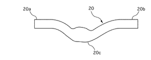
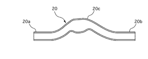
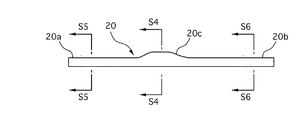
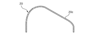
図1は本発明の実施例1のフォーム品20の平面図、図2は同底面図、図3は同正面図、図4は図3のS4−S4線における端面図、図5は図3のS5−S5線における端面図、図6は図3のS6−S6線における端面図である。
Example 1 will be described below.
1 is a plan view of a
図7は本実施例1のフォーム品20の製造に用いられるプレス成形加工装置を説明する図、図8はプレス成形加工装置によるフォーム品20の製造を説明する図、図9は本実施例1のフォーム品の端部の切断を説明する図である。
FIG. 7 is a diagram for explaining a press molding processing apparatus used for manufacturing the
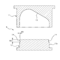
図10は本実施例1のリストライク品の製造に用いられるリストライク加工装置を説明する図、図11はリストライク加工装置によるリストライク品の製造を説明する図、図12は本実施例1の要部拡大図であり、リストライク加工時の作用を説明する図である。 FIG. 10 is a diagram for explaining the wrist-like processing apparatus used for manufacturing the wrist-like product according to the first embodiment, FIG. 11 is a diagram for explaining the manufacturing of the wrist-like product by the wrist-like processing apparatus, and FIG. 12 is the first embodiment. FIG. 6 is an enlarged view of a main part of the figure, and is a diagram for explaining an action at the time of wrist-like processing.
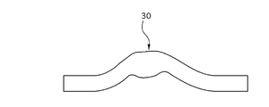
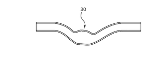
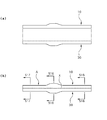
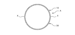
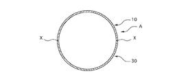
図13は本実施例1のリストライク品30の平面図、図14は同底面図、図15は本実施例1のリストライク品10,30の接合を説明する図、図16は図15(b)のS16−S16線における端面図、図17は図15(b)のS17−S17線における端面図、図18は図15(b)のS18−S18線における端面図である。
13 is a plan view of the wrist-
本実施例1の金属製管状部材Aを製造するには、先ず、厚みが0.5〜1.0mmのステンレス製の平板からなる素材1を後述する公知のプレス成形加工装置2を用いて、図1〜6に示すフォーム品20を形成する。
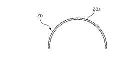
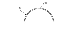
本実施例1のフォーム品20は、その長手方向両端部が半円形状の断面を有する直線部分20a,20bで構成され、長手方向中央部が湾曲して略三角形状の断面を有する膨出部20cで構成されている。なお、フォーム品20の断面形状は適宜設定できる。
In order to manufacture the metallic tubular member A of the first embodiment, first, using a known
The
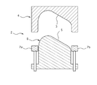
図7に示すように、プレス成形加工装置2は、製造すべきフォーム品20の外周面と合致する形状の凹部3を備える上型4と、製造すべきフォーム品20の内周面と合致する形状の凸部5を備える下型6と、一対のチャック機構7a,7bと、上下型4,6を互いに近接及び離間させて停止可能な図外の駆動装置と、一対のチャック機構7a,7bを上下方向に移動させる図外の駆動装置から構成されている。なお、これらの駆動装置は一般的なエア式または油圧式のシリンダが採用される。
As shown in FIG. 7, the
そして、図8(a)に示すように、図外の駆動装置によりチャック機構7a,7bを上方に移動させて、上型4の下端部との間に素材1を挟み込んだ状態として、図8(b)に示すように、図外の駆動装置により下型6を上方に移動させて、凸部5を上型4の凹部3に進入させることにより、素材1をプレス成形加工する。
この際、チェック機構7a,7bを緩めて素材1を少しずつ上下型4,6の凹部3と凸部5の間に送り込むようにしても良い。
Then, as shown in FIG. 8A, the
At this time, the
次に、図9に示すように、上記プレス成形加工された素材1を所定の切断位置で切断することにより、両端部にそれぞれ平板状の直線部8を有するフォーム品20を得る。
この際、フォーム品20の断面周長は製造すべきリストライク品10の101%〜101.5%となるように、上記切断位置、換言すると直線部8の長さが設定されている。
Next, as shown in FIG. 9, the press-molded
At this time, the cutting position, in other words, the length of the
次に、上記フォーム品20を後述するリストライク加工装置9を用いてリストライク加工することにより、リストライク品10を得る。
図10に示すように、リストライク加工装置9は、上型11と、下型12と、上下型11,12を互いに近接及び離間させて停止可能な図外の駆動装置から構成されている。なお、この駆動装置は一般的なエア式または油圧式のシリンダが採用される。
Next, the wrist-
As shown in FIG. 10, the wrist-
上型11には、フォーム品20の直線部8を含む外周面に合致する形状の凹部13が形成されている。
一方、下型12には、本体12aからフォーム品20の直線部8の厚み及び幅と同じ厚みW1及び長さW2を有し、フォーム品20の直線部8の端部8a及び直線部8の内側に合致する形状の凸部14が対を成して形成されている。
The
On the other hand, the
そして、図11に示すように、下型12の凸部14にフォーム品20の両直線部8を合致させた状態とし、下型12をフォーム品20と共に上型の凹部13に進入させて、これら上下型11,12の間でフォーム品20をリストライク加工することにより、リストライク品10を得る。
Then, as shown in FIG. 11, the both
この際、図12に示すように、フォーム品20の両端部において、直線部8の端部8a及び直線部8の内周面8bが、下型12の凸部14の押圧面14a及び凸部の側面14bに当接する他、直線部8の外周面8cが、上型11の凹部13に当接するため、フォーム品20の直線部8の外周面8c及び内周面8bを凹部13及び凸部14の側面14aで支持しつつ、凸部14の押圧面14aで直線部8の端部8aを押圧してフォーム品20を略U字状の断面方向(図10の波線矢印で図示)に圧縮でき、これによって、直線部8の端部8aを平坦に整えることができる。
At this time, as shown in FIG. 12, at both ends of the
ここで、従来の発明にあっては、フォーム品の端部がプレス成形加工した際の残留応力よって変形したり、プレス成形加工後に端部をガス切断する際の熱応力によって変形してしまう上、その後のリストライク加工においてリストライク量が不足した場合には、フォーム品の端部が圧縮前の元の形状に戻る所謂スプリングバックが発生し、リストライク量が過大の場合には、フォーム品の端部が座屈・亀裂してしまい、高精度で安定した形状のリストライク品を得られないという問題点があった。
なお、従来品で実験した結果、平均3.0mmのスプリングバックが発生し、膨出部分20cにおいて最大4.8mmのスプリングバックが発生した。
Here, in the conventional invention, the end portion of the foam product is deformed by the residual stress at the time of press forming, or deformed by the thermal stress at the time of gas cutting the end portion after the press forming process. If the amount of re-striking is insufficient in the subsequent re-striking process, a so-called springback occurs in which the end of the foam product returns to its original shape before compression, and if the re-striking amount is excessive, the foam product As a result, there is a problem that a highly accurate and stable re-stoic product cannot be obtained.
As a result of experiments with conventional products, a springback of 3.0 mm on average occurred, and a maximum of 4.8 mm of springback occurred in the bulging
しかしながら、本実施例1の金属製管状部材Aの製造方法では、上述したように、フォーム品20の直線部8の外周面8cと内周面8bを凹部13と凸部14の側面14aで支持しつつ、凸部14の押圧面14aで直線部8の端部8aを押圧してフォーム品20を略U字状の断面方向に圧縮するため、フォーム品20の端部に掛かる内側に座屈する方向の応力を緩和でき、これによって、フォーム品20の端部が内側に撓んで座屈・亀裂するのを防止できる上、フォーム品20を全体的に圧縮して安定した形状に形成できる。
However, in the method for manufacturing the metal tubular member A of the first embodiment, as described above, the outer
また、下型12の凸部14は、フォーム品20に対して直線部8の端部8aと直線部8の内周面8b以外の部位に接触させる必要がないため、コンパクト化して金型費を削減できる。
Further, since the
また、フォーム品20の断面形状に依存しないため、断面形状の異なる複数種類のフォーム品20に対応できる。
Moreover, since it does not depend on the cross-sectional shape of the
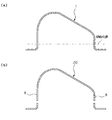
最後に、上記と同様のプレス加工装置2及びリストライク加工装置9を用いて図13、14に示すリストライク品10と対称形状のリストライク品30を形成して、図15に示すように、これら一対のフォーム品10,30の直線部8の端部8a同士を溶接Xすることにより、所望の金属製管状部材Aを得る(図16〜18参照)。
Finally, a wrist-
ここで、リストライク加工前のフォーム品20の断面周長に対するリストライク量(圧縮率)を様々に代えてリストライク加工した試験結果を表1に示す。なお、試験に用いたフォーム品20は板厚0.5mmのステンレス製(SUS304)であり、フォーム品30についても全く同じ結果となった。
Here, Table 1 shows the test results of the re-striking process by varying the re-striking amount (compression ratio) with respect to the cross-sectional circumference of the
表1から明らかなように、0%≦リストライク量(圧縮率)<1.0%では、スプリングバック量が1.0mmよりも小さくなることがなく、結果、一対のフォーム品10,30の直線部8の端部8a同士を接合した際に、2mm以上の隙間が生じて良好に溶接できない虞がある。
一方、リストライク量>1.5%に設定すると、フォーム品20の直線部8等に亀裂・破損が生じた。
また、フォーム品20の肉厚を0.5〜1.0mmに代えて試験した場合も同様の結果が得られた。
As is apparent from Table 1, when 0% ≦ restriction amount (compression ratio) <1.0%, the springback amount does not become smaller than 1.0 mm, and as a result, the pair of
On the other hand, when the amount of re-striking was set to> 1.5%, the
Similar results were obtained when the thickness of the
従って、実際上の製品としてはリストライク量をリストライク加工前のフォーム品20の断面周長の1.0〜1.5%とした場合に最も製品精度と信頼性の高いリストライク品10を得ることができる。
Therefore, as an actual product, when the amount of re-striking is 1.0 to 1.5% of the cross-sectional circumference of the
次に、効果を説明する。
以上、説明したように、本実施例1の金属製管状部材Aの製造方法にあっては、金属製管状部材Aを半割りにした形状のフォーム品20を上型11と下型12との間に挟みつつ、そのフォーム品20の端部をリストライク加工することにより、フォーム品20の端部を平坦に整えたリストライク品10を形成し、リストライク品10,30を一対としてその端部同士を溶接した金属製管状部材Aの製造方法において、フォーム品20の端部に平板状の直線部8を形成し、上型11に、フォーム品20の直線部8を含む外周面8cに合致する凹部13を設け、下型12に、フォーム品20の直線部8の端部8a及び直線部8の内周面8bに合致する凸部14を設け、フォーム品20を上型11と下型12との間に挟みつつ、そのフォーム品20の直線部8を該上型11の凹部13と該下型12の凸部14で支持させた状態でリストライク加工したため、高精度で安定した形状のリストライク品10を得ることができると共に、複数種類のフォーム品20に対応しつつ、金型費を削減できる。
Next, the effect will be described.
As described above, in the method for manufacturing the metallic tubular member A according to the first embodiment, the
また、フォーム品20をステンレス製とし、その肉厚を0.5mm〜1.0mmとした場合に、リストライク加工によるフォーム品20のリストライク量を、リストライク加工前のフォーム品20の断面周長の1.0〜1.5%としたため、製品品質と信頼性のリストライク品10を得ることができる。
Further, when the
以上、本実施例を説明してきたが、本発明は上述の実施例に限られるものではなく、本発明の要旨を逸脱しない範囲の設計変更等があっても、本発明に含まれる。
例えば、上型4、11は兼用させても良い。
また、フォーム品20の厚み、断面形状、直線部8の長さW2等については適宜設定でき、例えば、端部の変形量が大きい部位にのみ直線部8を設定するようにすることも考えられる。
Although the present embodiment has been described above, the present invention is not limited to the above-described embodiment, and design changes and the like within the scope not departing from the gist of the present invention are included in the present invention.
For example, the
Further, the thickness, the cross-sectional shape, the length W2 of the
A 金属製管状部材
1 素材
2 プレス成形加工装置
20、30 フォーム品
20a、20b 直線部分
20c 膨出部分
3、13 凹部
4、11 上型
5、14 凸部
6、12 下型
12a 本体
7a、7b チャック機構
8 直線部
8a (直線部の)端部
8b (直線部の)内周面
8c (直線部の)外周面
9 リストライク加工装置
10 リストライク品
14a (凸部の)押圧面
14b (凸部の)側面
A
Claims (1)
前記リストライク品を一対としてその端部同士を溶接した金属製管状部材の製造方法において、
前記フォーム品の端部に平板状の直線部を形成し、
前記上型に、前記フォーム品の直線部を含む外周面に合致する凹部を設け、
前記下型に、前記フォーム品の直線部の端部及び直線部の内周面に合致する凸部を設け、
前記フォーム品を上型と下型との間に挟みつつ、該フォーム品の直線部を該上型の凹部と該下型の凸部で支持させた状態でリストライク加工したことを特徴とする金属製管状部材の製造方法。 The end of the foam product was flattened by re-striking the end of the foam product while sandwiching the foam product with the half-shaped metal tubular member between the upper mold and the lower mold. Forming restorative products,
In the method of manufacturing a metal tubular member in which the ends are welded together as a pair of the wrist-like product,
A flat linear portion is formed at the end of the foam product,
The upper mold is provided with a recess that matches the outer peripheral surface including the straight portion of the foam product,
Providing the lower mold with a convex portion that matches the end of the straight portion of the foam product and the inner peripheral surface of the straight portion,
It is characterized in that the foam product is restricked in a state where the linear part of the foam product is supported by the concave portion of the upper die and the convex portion of the lower die while sandwiching the foam product between the upper die and the lower die. A method for producing a metal tubular member.
Priority Applications (1)
| Application Number | Priority Date | Filing Date | Title |
|---|---|---|---|
| JP2005367436A JP2007167883A (en) | 2005-12-21 | 2005-12-21 | Method for manufacturing metallic tubular member |
Applications Claiming Priority (1)
| Application Number | Priority Date | Filing Date | Title |
|---|---|---|---|
| JP2005367436A JP2007167883A (en) | 2005-12-21 | 2005-12-21 | Method for manufacturing metallic tubular member |
Publications (1)
| Publication Number | Publication Date |
|---|---|
| JP2007167883A true JP2007167883A (en) | 2007-07-05 |
Family
ID=38295125
Family Applications (1)
| Application Number | Title | Priority Date | Filing Date |
|---|---|---|---|
| JP2005367436A Pending JP2007167883A (en) | 2005-12-21 | 2005-12-21 | Method for manufacturing metallic tubular member |
Country Status (1)
| Country | Link |
|---|---|
| JP (1) | JP2007167883A (en) |
Cited By (1)
| Publication number | Priority date | Publication date | Assignee | Title |
|---|---|---|---|---|
| KR200482424Y1 (en) * | 2016-04-22 | 2017-01-20 | 주식회사 케이에이치테크 | Manufacturing apparatus for windbreak |
-
2005
- 2005-12-21 JP JP2005367436A patent/JP2007167883A/en active Pending
Cited By (1)
| Publication number | Priority date | Publication date | Assignee | Title |
|---|---|---|---|---|
| KR200482424Y1 (en) * | 2016-04-22 | 2017-01-20 | 주식회사 케이에이치테크 | Manufacturing apparatus for windbreak |
Similar Documents
| Publication | Publication Date | Title |
|---|---|---|
| JP5433243B2 (en) | Square pipe, frame structure, square pipe manufacturing method, and square pipe manufacturing apparatus | |
| TWI528616B (en) | Method and apparatus for manufacturing a safety valve for a battery, safety valve for a battery, and method for manufacturing a lid of a battery case | |
| KR101996155B1 (en) | Method for manufacturing molded article, mold, and tubular molded article | |
| US9364883B2 (en) | Method of producing a separator | |
| JP2008514429A5 (en) | ||
| CN107073542A (en) | The manufacture method of compressing product and compressing product | |
| JP2009037980A (en) | Battery can and metal can blank, and battery can and metal can manufacturing method using the same | |
| JP2004034063A (en) | Pipe body manufacturing method, pipe body, and image forming apparatus using this pipe body | |
| WO2018168563A1 (en) | Press mold and method for manufacturing steel pipe | |
| CN110709181A (en) | Manufacturing method of press-molded product and press production line | |
| JP7302747B2 (en) | Method for manufacturing press-formed product and press-forming apparatus | |
| US7237423B1 (en) | Apparatus for stretch forming blanks | |
| JP2018061979A (en) | Pipe manufacturing method and press device used therein | |
| EP2946849A1 (en) | Method for manufacturing metal component with three-dimensional edge, and die for manufacturing | |
| JP6052054B2 (en) | Method of bending metal sheet | |
| CN100415401C (en) | Punch device for U-shaped punching machine in UOE steel pipe manufacturing process | |
| JP6729011B2 (en) | Method for manufacturing closed-section structural member and upper mold for O molding | |
| JP2007167883A (en) | Method for manufacturing metallic tubular member | |
| JP5646137B2 (en) | Rack bar | |
| JP7036195B2 (en) | Manufacturing method of molded products | |
| JP2025091461A (en) | Metal can manufacturing method and die set | |
| JP2001191112A (en) | Method and apparatus for forming tubular member having rectangular cross section | |
| JP5157716B2 (en) | Method for manufacturing universal joint yoke | |
| JP2017192978A (en) | Mold, manufacturing method of u-shaped molding, and manufacturing method of tubular molding | |
| JP2001300652A (en) | Piercing method and die in hydraulic bulging of metal tube |
