CN101589868B - Device for creating a seal between fabrics or other materials - Google Patents
Device for creating a seal between fabrics or other materials Download PDFInfo
- Publication number
- CN101589868B CN101589868B CN2008101748476A CN200810174847A CN101589868B CN 101589868 B CN101589868 B CN 101589868B CN 2008101748476 A CN2008101748476 A CN 2008101748476A CN 200810174847 A CN200810174847 A CN 200810174847A CN 101589868 B CN101589868 B CN 101589868B
- Authority
- CN
- China
- Prior art keywords
- seal
- slide block
- endless
- lower seal
- mating surface
- Prior art date
- Legal status (The legal status is an assumption and is not a legal conclusion. Google has not performed a legal analysis and makes no representation as to the accuracy of the status listed.)
- Expired - Fee Related
Links
Images


Classifications
-
- A—HUMAN NECESSITIES
- A44—HABERDASHERY; JEWELLERY
- A44B—BUTTONS, PINS, BUCKLES, SLIDE FASTENERS, OR THE LIKE
- A44B19/00—Slide fasteners
- A44B19/24—Details
- A44B19/32—Means for making slide fasteners gas or watertight
-
- A—HUMAN NECESSITIES
- A44—HABERDASHERY; JEWELLERY
- A44B—BUTTONS, PINS, BUCKLES, SLIDE FASTENERS, OR THE LIKE
- A44B19/00—Slide fasteners
- A44B19/10—Slide fasteners with a one-piece interlocking member on each stringer tape
- A44B19/16—Interlocking member having uniform section throughout the length of the stringer
-
- A—HUMAN NECESSITIES
- A44—HABERDASHERY; JEWELLERY
- A44B—BUTTONS, PINS, BUCKLES, SLIDE FASTENERS, OR THE LIKE
- A44B19/00—Slide fasteners
- A44B19/24—Details
- A44B19/26—Sliders
- A44B19/267—Sliders for slide fasteners with edges of stringers having uniform section throughout the length thereof
-
- Y—GENERAL TAGGING OF NEW TECHNOLOGICAL DEVELOPMENTS; GENERAL TAGGING OF CROSS-SECTIONAL TECHNOLOGIES SPANNING OVER SEVERAL SECTIONS OF THE IPC; TECHNICAL SUBJECTS COVERED BY FORMER USPC CROSS-REFERENCE ART COLLECTIONS [XRACs] AND DIGESTS
- Y10—TECHNICAL SUBJECTS COVERED BY FORMER USPC
- Y10T—TECHNICAL SUBJECTS COVERED BY FORMER US CLASSIFICATION
- Y10T24/00—Buckles, buttons, clasps, etc.
- Y10T24/25—Zipper or required component thereof
- Y10T24/2532—Zipper or required component thereof having interlocking surface with continuous cross section
- Y10T24/2534—Opposed interlocking surface having dissimilar cross section
-
- Y—GENERAL TAGGING OF NEW TECHNOLOGICAL DEVELOPMENTS; GENERAL TAGGING OF CROSS-SECTIONAL TECHNOLOGIES SPANNING OVER SEVERAL SECTIONS OF THE IPC; TECHNICAL SUBJECTS COVERED BY FORMER USPC CROSS-REFERENCE ART COLLECTIONS [XRACs] AND DIGESTS
- Y10—TECHNICAL SUBJECTS COVERED BY FORMER USPC
- Y10T—TECHNICAL SUBJECTS COVERED BY FORMER US CLASSIFICATION
- Y10T24/00—Buckles, buttons, clasps, etc.
- Y10T24/25—Zipper or required component thereof
- Y10T24/2561—Slider having specific configuration, construction, adaptation, or material
- Y10T24/2582—Slider having specific configuration, construction, adaptation, or material having specific contour or arrangement of converging channel, separator island, or wing
- Y10T24/2584—Spaced segments of each wall of channel supported by different wings
Abstract
A device for forming a seal includes upper and lower seal members, and a slider, wherein mating surfaces of the seal members interlock. In at least one embodiment, a lifting rib and closure bar on the slider cooperate with a lifting wing and closure bar groove on the upper and lower seal members, respectively. By moving the slider in one direction, the lifting rib lifts the upper seal member from the lower seal member. Moving the slider in the opposite direction causes the upper and lower seal members to interlock. In another embodiment, a slider has an intermediate lateral member connected on one side the slider top, and connected on the other side to the slider bottom. A breakaway sealing device is also provided, allowing a person to break the closed seal. A beginning stop block is also provided that includes a means for securing the upper seal member.
Description
The application is that application is artificial: Mibi Innovation Co., Ltd; The applying date is: on October 25th, 2005; Priority date is: on October 25th, 2004, application number is: 200580043780.7, and name is called: the invention of the device of foundation sealing divides an application between fabric or other material.
Technical field
The present invention relates to a kind of device that can between fabric or other material, set up sealing.
Background technology
Tightening device typically comprises the part that tooth is arranged of two flexible elongated, makes two part interlocking or separation through the slide block that moves along it.Although this tightening device is used for sealing and open various article for a long time, for example clothes and pocket, this device but allows liquids and gases entering fastener, and can not be used for the article of windproof, the airtight and/or waterproof of needs.
Fluid sealing fastener is utilizable, but this fastener typically can not the fluid sealing in its end.In addition, also have other to have the device of arrangement adjacent one another are and part that can be separated from one another.Also has other device, its costliness, heaviness and/or need to use cladding material to cover fastener to realize the sealing of wind and/or watertightness.
Also need a kind of Endless sealing device to be used for making first part to be connected, for example gloves or boots are connected to the dangerous waste material protective garment with second part.
Also need a kind of sealing device, it provides a kind of profile quite little slide block, and this slide block is operated with adjacent direction roughly opposite last seal and lower seal.For example, the slide block of seal and lower seal in a kind of operation that is used for jacket is set, waterproof and windproof property along seal length are provided thus, have less relatively profile simultaneously and go up seal and lower seal seems roughly open and flat.
Also need a kind of zipper system, its permission soldier or emergency personnel are in sternness or in emergency circumstances go out sleeping bag.In the case, the not free or ability of the user of sleeping bag again with its notice concentrate on grope the slide fastener sheet and zip on because under the compromised situation of extreme anxiety and/or life these devices of operation difficulty too.The typical sleeping bag of the outfit conventional zipper that prior art provides, it can not allow the user to run away fast and leave sleeping bag in nervous situation or bad weather condition.Therefore, need a kind of very easy operation, can leave fast, waterproof and the inexpensive sleeping bag of running away (or parcel article of replacement).
Also need a kind ofly to make slide block, go up the device that seal and lower seal combine, wherein this device can be installed in seal the end to keep the position of seal with respect to lower seal, promote slide block along the upper-lower seal part then and form and seal.
Also need various fit shapes the sealing of watertight and anti-gas transfer to be provided, the sealing that also provides effective anti-accident to open simultaneously.
Summary of the invention
Characteristics of the present invention are to provide a kind of sealing that is used to have the surperficial object of two relative material, keep Slipper always to be positioned at the outside of seal simultaneously.
In first embodiment, sealing device comprises three main parts: seal is gone up in (1); (2) lower seal; (3) slide block.Slide block comprises at least one lifting rib and closure strip.During use, the length of slide block leap seal moves forward and backward and makes seal and lower seal interlocking, forms sealing.More particularly, slide block comprises restricted part, and it will be gone up seal when slide block and be pressed into lower seal when closing direction moves.Open when sealing, the lifting rib in the slide block is extracted last seal from the lower seal that is closed bar and is anchored on slider bottom.
In the modification of first embodiment, be provided with a kind of slide block, it only comprises a lifting rib in the opening section of slide block.The closing section of slide block comprises closure strip, its lower seal and make slide body will go up seal to be pressed into lower seal and to accomplish sealing of linking closely.Closing section can comprise sloping portion, slightly rotates when its inclination makes seal get into lower seal, improves airtight quality thus.The opening section of revising embodiment preferably includes a lifting rib, and the last seal that lifting rib is lifted under its lifting wing makes that going up seal separates from lower seal.From the lower seal separation is owing to preferably prolonged the bottom that the closure strip of slide block length is held in lower seal slide block.When using a lifting rib, opening section make to be gone up when seal withdraws from lower seal and is slightly rotated, and improves the easy property that slide block moves and the durability of airtight quality thus.
In a second embodiment, waterproof seal comprises four main parts: seal is gone up in (1); (2) lower seal; (3) slide block; (4) connector.The last seal of this embodiment does not need the lifting wing.And lower seal does not need the closure strip groove.The slide block of this embodiment has internal structure and cooperates the sealing surfaces of going up seal and lower seal to make its combination.And, the similar funnel-form of internal structure shape of slide block.One section seal moves when the slide block edge, and slide block is closed seal to form sealing at its blind end.That is to say, last seal and lower seal through funnel-form combine.When opening the direction use, on the contrary, the internal structure of seal will go up seal and separate from lower seal.
Another embodiment of the present invention uses connector to form waterproof sealing at the end of seal.Connector is permanently affixed at the end of seal.And connector comprises internal structure combines the mating surface of seal and lower seal.In addition, when slide block moved to its closed position, the structure and the slide block of connector closely cooperated.Thus, when slide block and connector moved to its closed position, the mating surface of last seal and lower seal formed sealing around slide block and connector internal structure.
According at least one embodiment of the present invention, sealing device comprises the slide block with crooked lifting wing.More particularly; A kind of sealing device of setting up or forming sealing is provided; The sealing device comprises slide block, has first or last seal of first mating surface and the lifting wing, has second or lower seal of second mating surface and closure strip groove, wherein second mating surface and the first mating surface interlocking.Slide block comprises lifting rib, the lifting wing slip of lifting rib and last seal movingly, the primary importance of lifting rib from slide block is radial to the second place of the opening end of slide block and curves inwardly.In addition, slide block comprises the closure strip that the closure strip groove with lower seal is slidingly matched.Slide block also comprises main body, and it has closing end, wherein lifting rib in the closing end closure near closure strip, and wherein lifting rib in the opening end opening near closure strip.Slide block last seal in edge and lower seal move the upper-lower seal part are passed to closing end from the opening end of slide block, and slide block makes first mating surface get into second mating surface, form sealing thus.
According at least one embodiment of the present invention, at least one is processed by the material of two kinds of different hardness at least in last seal and the lower seal.
According at least one embodiment of the present invention, at least one comprises the reinforcement mold insert in last seal and the lower seal.
According at least one embodiment of the present invention, the main body of slide block comprises the top with inner surface, and said inner surface comprises fin, and the groove fit of fin and last seal upper surface when slide block moves along last seal, makes slide block keep suitable aligned.
According at least one embodiment of the present invention, the main body of slide block comprises that part is cylindrical, and it is arranged in and last seal and at least one position contacting of lower seal.
According at least one embodiment of the present invention, last seal and lower seal all have start-up portion, mid portion and end portion, wherein go up the lifting wing on the seal at mid portion and not in start-up portion and end portion.
According at least one embodiment of the present invention, slide block also comprises pull head, pin and inclination pull head track, and pull head is positioned at the pull head track.
According at least one embodiment of the present invention, last seal and lower seal all are connected to the adjacent materials surface, wherein the adjacent materials almost parallel.
According at least one embodiment of the present invention, last seal and lower seal all are connected to the adjacent materials surface, adjacent materials coplane roughly wherein, contiguous first and second mating surfaces.
According at least one embodiment of the present invention, first and second mating surfaces all comprise the protruding profile of at least one hourglass shape.
According at least one embodiment of the present invention, first and second mating surfaces comprise that all at least one makes up protruding profile, and it has first limit of general hourglass and second limit of mushroom-shaped roughly.
According at least one embodiment of the present invention, last seal and lower seal be continuous with form headring for no reason, and seal comprises the Endless sealing.
According at least one embodiment of the present invention, slide block comprises the top of locking releasedly, and can comprise hinge.
At least one embodiments of the invention provides new advantage or the structure that forms the Endless sealing is provided.Like this, according at least one embodiment of the present invention, the device that forms the Endless sealing comprises: (a) first of Endless or go up seal and have first mating surface; (b) second of Endless or lower seal have second mating surface, wherein second mating surface and the first mating surface interlocking; (c) have the slide block at the top of locking releasedly, slide block makes first mating surface and the second mating surface interlocking.In the time can discharging the top and be positioned at first enable possition; Seal is positioned at the position on the inherent at least a portion Endless of the slide block lower seal at least a portion Endless; Wherein the top of locking can be positioned at second latched position releasedly; Wherein seal is to the Endless lower seal on the slide block locking Endless, and wherein slide block can move along seal on the Endless and Endless lower seal, and the first and second mating surface interlocks are sealed with the formation Endless.
According at least one embodiment of the present invention, the cross section of Endless seal is roughly circle.
According at least one embodiment of the present invention, seal has the lifting wing on the Endless, and the Endless lower seal has the closure strip groove, and slide block comprises: (i) with Endless on the lifting wing of seal cooperate the lifting rib of sliding; (ii) cooperate the closure strip of sliding with the closure strip groove of Endless lower seal; (iii) main body, it has closing end, and wherein lifting rib is closed near closure strip, and opening end, and wherein lifting rib is open near closure strip.Slide block can slide so that the upper-lower seal part passes through to closing end from the opening end of slide block along seal on the Endless and Endless lower seal; Slide block can slide into terminal position from the starting position along one section Endless upper-lower seal part, and wherein terminal position is positioned at least one with upper/lower positions: (A) starting position; (B) roughly near the starting position, wherein slide block makes the cooperation that contacts with second mating surface of first mating surface, forms the Endless sealing thus.
According at least one embodiment of the present invention, the top of locking has inner surface releasedly, and inner surface comprises fin, its with Endless on the groove fit of upper surface of seal so that in slide block suitable location of maintenance when seal moves on Endless.
According at least one embodiment of the present invention, slider body comprises that part is cylindrical, its be arranged in Endless on seal and at least one position contacting of Endless lower seal.
According at least one embodiment of the present invention, seal comprises barbed portion on the Endless, does not wherein have the lifting wing.
According at least one embodiment of the present invention, the device that forms the Endless sealing comprises: (a) have seal on the Endless of first mating surface; (b) has the Endless lower seal of second mating surface, wherein second mating surface and the first mating surface interlocking; (c) slide block, it moves along seal on the Endless and lower seal and makes first mating surface and the second mating surface interlocking, forms the Endless sealing thus.
According at least one embodiment of the present invention, Endless seal or Endless closure member comprise wherein at least one (a) anti-gas transfer seal; (b) gastight seal; (c) anti-watertight seal; (d) waterproof seal; (e) the permeable seal of fluid; (f) the permeable seal of gas.
According at least one embodiment of the present invention; When the top of locking releasedly is positioned at first enable possition; Seal is positioned at the position on the inherent at least a portion Endless of the slide block lower seal at least a portion Endless; Wherein the top of locking can be positioned at second latched position releasedly; Wherein seal is to the Endless lower seal on the slide block locking Endless, and wherein slide block can move along seal on the Endless and Endless lower seal, first and second mating surfaces is cooperated with the formation Endless seal.
According at least one embodiment of the present invention, seal has the lifting wing on the Endless, and the Endless lower seal has the closure strip groove, and slide block comprises: (i) with Endless on the lifting wing of seal cooperate the lifting rib of sliding; (ii) cooperate the closure strip of sliding with the closure strip groove of Endless lower seal; (iii) main body, it has closing end, and wherein lifting rib is closed near closure strip, and opening end, and wherein lifting rib is open near closure strip.Slide block can slide so that the upper-lower seal part passes through from the opening end to the closing end in slide block along seal on the Endless and Endless lower seal; Slide block can slide into terminal position from the starting position along one section Endless upper-lower seal part, and wherein terminal position is positioned at least one with upper/lower positions: (A) starting position; (B) roughly near the starting position, wherein slide block makes the cooperation that contacts with second mating surface of first mating surface, forms the Endless sealing thus.
According at least one embodiment of the present invention, form the closed device of Endless and comprise: (a) the first Endless closure member; (b) the second Endless closure member, the wherein second Endless closure member and the first Endless closure member interlocking; And (c) device, it moves and makes the first Endless closure member and the second Endless closure member interlocking along first and second Endless closure members, forms the Endless closure thus.
According at least one embodiment of the present invention, the first Endless closure member comprises first mating surface, the second mating surface interlocking of itself and the second Endless closure member.
According at least one embodiment of the present invention, a kind of new equipment that forms sealing is provided, wherein slide block does not comprise lifting rib and does not comprise closure strip.Similarly, first or go up seal and do not comprise the lifting wing, and second or lower seal do not comprise the closure strip groove.Like this,, a kind of sealing device is provided, has comprised that (a) has the last seal of first mating surface according at least one embodiment of the present invention; (b) has the lower seal of second mating surface, wherein second mating surface and the first mating surface interlocking; And (c) slide block, it makes first mating surface and the second mating surface interlocking, and slide block has middle side member, and it only has first limit to be connected with slide block top and only has second limit to be connected with the slide block bottom.Slide block can along last seal and lower seal slide so that the upper-lower seal part in slide block from the opening end of slide block to the closing end process, wherein slide block makes cooperations that contact with second mating surface of first mating surface, formation seals thus.
According at least one embodiment of the present invention, middle side member comprises first rib and second rib downwards roughly upwards roughly, and first rib cooperated and goes up seal when slide block moved along last seal, and slide block second rib when lower seal moves cooperates lower seal.
According at least one embodiment of the present invention, be provided with a kind of initial limited block in the end of lower seal, initial limited block comprises the device of seal on the releasably locking.
According at least one embodiment of the present invention, the closing end of slide block at moving slider to form the sealing anteposition near initial limited block.
According at least one embodiment of the present invention, releasable locking mechanism comprises the convexity that embeds the hole of going up seal.
According at least one embodiment of the present invention, releasable locking mechanism has been used a kind of (i) at least makes seal be secured to the frictional force of initial limited block; (ii) make seal be secured to the magnetic force of initial limited block.
According at least one embodiment of the present invention, slide block breaks away from the upper-lower seal part in one of following at least situation, and one of them is individual; (i) on or the end of lower seal; (ii) go up or the breach of lower seal, wherein the length with slide block is the same long at least for the length of breach.
According at least one embodiment of the present invention, be provided with a kind of initial limited block in the end of last or lower seal, limited block comprises and being fixed tightly in releasedly or the lower seal device of one of which at least.
According at least one embodiment of the present invention, through applying separating force between upper and lower seal, last seal can separate from lower seal, and wherein slide block does not hinder seal to separate from lower seal along one section arbitrary part that goes up seal.
According at least one embodiment of the present invention, using the product of the sealing device of running away is sleeping bag.
According at least one embodiment of the present invention, lower seal comprises double lower seal, and it comprises first and second mating surfaces, and wherein first and second mating surfaces are separated.According at least one embodiment of the present invention, be provided with double lower seal interlocking second on seal.
According at least one embodiment of the present invention, a kind of device that forms sealing is provided, this device comprises: the last seal that (a) has first mating surface; (b) has the lower seal of second mating surface, wherein second mating surface and the first mating surface interlocking; (c) make the slide block of first mating surface and the second mating surface interlocking; Slide block has middle side member; Middle side member has leading edge, the top that slide block has at least a (i) has top forward edge, and top forward edge longitudinally is positioned at after the leading edge of middle side member; The bottom that (ii) has bottom front edge, bottom front edge longitudinally are positioned at after the front portion of middle side member.Slide block can along last seal and lower seal slide so that the upper-lower seal part in slide block from the opening end of slide block to the closing end process, wherein slide block makes cooperations that contact with second mating surface of first mating surface, formation seals thus.According at least one embodiment of the present invention, only in the middle of first side of side member contact with the top of slide block and only second side of centre side member contact with the bottom of slide block.According at least one embodiment of the present invention, middle side member comprises first roughly rib and second rib downwards roughly up, and first rib cooperated and goes up seal when slide block moved along last seal, and slide block second rib when lower seal moves cooperates lower seal.
According at least one embodiment of the present invention, a kind of sealing device of running away is provided, it comprises: the last seal that (a) has first mating surface; (b) has the lower seal of second mating surface, wherein second mating surface and the first mating surface interlocking; And (c) make the slide block of first mating surface and the second mating surface interlocking.Slide block can slide so that upper-lower seal part opening end from slide block in slide block passes through to closing end along last seal and lower seal; Wherein slide block makes the cooperation that contacts with second mating surface of first mating surface; Form sealing thus, wherein slide block one of following at least situation break away from the upper-lower seal part one of them; (i) on or the end of lower seal; (ii) go up or the breach of lower seal, wherein the length with slide block is the same long at least for the length of breach.Slide block can separate from last or lower seal, and through applying separating force between upper and lower seal, last seal can separate from lower seal, and wherein slide block does not hinder seal to separate from lower seal along one section arbitrary part that goes up seal.
According at least one embodiment of the present invention, the separating force of the sealing device of running away can be produced by the short parting material that links to each other with upper and lower seal.
According at least one embodiment of the present invention; The slide block that is used for sealing device can comprise middle side member; Middle side member has leading edge, and the top that (i) has top forward edge one of below slide block has at least at least is in the middle of top forward edge longitudinally is positioned at after the leading edge of side member; The bottom that (ii) has bottom front edge, bottom front edge longitudinally are positioned at after the front portion of middle side member; According at least one embodiment of the present invention, the seal that is used in aforementioned slide block does not comprise the closure strip or the lifting wing.
Comprise product according to the sealing device of at least one embodiment of the present invention; It can comprise hazardous material protective garment, fire-entry suit, dry clothes, dry bag, camping bag, wader, space suit, tent, transportation and packing, family's storage bag, map container, sea chart container, boat skirt, knapsack cover, calculating hood, electronic installation case, ship case, aeration vessel, floating bag, flotation gear, waterproof pocket, fishing vest pocket, Deodorizing bag, diving suit, jacket, sleeping bag, rain gear, boots, boat jacket, windbreaker and Wind proof overcoat.
In the accompanying drawings and in the detailed description of the invention implemented of provided herein and claims, provided various embodiment of the present invention.But should understand like this: this summary to invention possibly not comprise all aspects of the present invention and all embodiment; Neither be intended to limit or have limited in any form; Invention disclosed herein or will be had present technique field those skilled in the art and understand, to obtain conspicuous improvement and modification.
Particularly combine the argumentation of accompanying drawing can easily understand other advantage of the present invention from following argumentation.
Description of drawings
Shown that some accompanying drawings are to help to understand the present invention.It below is the brief description of drawings of explanation the present invention and its various embodiment.
Fig. 1 is the perspective view of the waterproof seal of first embodiment of the invention;
Fig. 2 is the last seal of first embodiment of the invention and the perspective view of lower seal;
Fig. 3 is the profile of the upper-lower seal part of Fig. 2 along the 3-3 line;
Fig. 4 is the side view of the slide block assembly in the upper-lower seal part of the preferred embodiment of the present invention;
Fig. 5 is the perspective view of structure shown in Figure 4;
Fig. 6 is the cutaway view along the 6-6 line of the slide block closing end of Fig. 5;
Fig. 7 is the perspective view of opening end of the slide block assembly of preferred embodiment;
Fig. 8 is the perspective view of closing end of the slide block assembly of preferred embodiment;
Fig. 9 a is the sectional view of sealing section, and slide block wherein has long closure strip;
Fig. 9 b is the sectional view of sealing section, and slide block wherein has the closure strip of moderate-length;
Fig. 9 c is the sectional view of sealing section, and slide block wherein has short closure strip;
Fig. 9 d is the sectional view of sealing section, and slide block wherein has the closure strip of outstanding shape;
Fig. 9 e is the sectional view of sealing section, and slide block wherein has the closure strip that is positioned at the outstanding shape of sustained height with seal;
Fig. 9 f is the sectional view of sealing section, and slide block wherein has the closure strip of outstanding shape, and it has the end shape of replacement;
Fig. 9 g is the sectional view of sealing section, and slide block wherein has the closure strip that does not have end shape of moderate-length;
Fig. 9 h is the sectional view of sealing section, and slide block wherein has the lifting rib of top and sidepiece installation;
Fig. 9 i is the sectional view of sealing section, and slide block wherein has the lifting rib that install at the top;
Fig. 9 i is the sectional view of sealing section, and slide block wherein has the lifting rib that is positioned at the top installation of sustained height with seal;
Fig. 9 k is the sectional view of sealing section, and slide block wherein is cylindrical;
Figure 91 is the sectional view with the sealing section that colludes shape rigidity mold insert;
Fig. 9 m is the sectional view with improved sealing section with the flexural rigidity mold insert that is suitable for being placed in the seal that is arranged in sustained height;
Fig. 9 n is the sectional view with sealing section of the rigidity mold insert that is almost the plane;
Fig. 9 o is the sectional view of sealing section with stability ribs of the lower seal of being connected to;
Figure 10 is the sectional view that shows a plurality of possible shapes that are used for protruding matching surface part;
Figure 11 is the sectional view that shows the corresponding recessed matching surface part of describing with Figure 10 of protruding matching surface part;
Figure 12 is the sectional view that Figure 10 combines with the convex-concave matching surface part of Figure 11 description;
Figure 13 is the sectional view that shows the various groove pattern shapes that can be used for protruding matching surface part;
Figure 14 is the sectional view that shows the corresponding recessed matching surface of describing with Figure 13 of protruding matching surface part;
Figure 15 shows the sectional view that can append to the several additional shape patterns on the protruding matching surface part;
Figure 16 shows the sectional view that can append to the several additional shape patterns on the recessed matching surface part;
Figure 17 .1-17.11 shows the sectional view that can be used for adding several kinds of simple shape patterns making the matching surface part;
Figure 18 a be can with the last seal with identical shaped accurately lower seal interlocking;
Figure 18 b is the lower seal of the seal interlocking that can describe with Figure 18 a;
The sealing that the seal that Figure 18 c is to use Figure 18 a and Figure 18 b to describe forms;
Figure 19 is the perspective view of sealing device of the modification of first embodiment;
Figure 20 is the perspective view of the slide block of modification shown in Figure 19;
Figure 21 is the sectional view of the possible sealing section that can be used for being connected with slide block shown in Figure 20;
Figure 22 is the perspective view of the sealing device of modification shown in Figure 19, and wherein slide block is positioned near the end of sealing section;
Figure 23 is the perspective view that shows the end of the sealing section that cuts away the lifting wing;
Figure 24 is the front view towards the opening section direction of slide block of the slide block of modification shown in Figure 20;
Figure 25 is the front view towards the closing section direction of slide block of the slide block of modification shown in Figure 20;
Figure 26 is the front view towards the closing section direction of slide block of the slide block of the modification with upper-lower seal section shown in Figure 20;
Figure 27 is the front view towards the opening section direction of slide block of the slide block of the modification with upper-lower seal section shown in Figure 20;
Figure 28 is the perspective view of the second embodiment of the present invention;
Figure 29 is the perspective view of the replacement of the second embodiment of the present invention;
Figure 30 is the profile along the 30-30 line of Figure 28;
Figure 31 is the profile along the 31-31 line of Figure 29;
Figure 32 is the connector of second embodiment and the perspective view of slide block;
Figure 33 is the connector described of Figure 32 and the vertical view of slide block;
Figure 34 is the front view of the slide block described of Figure 32;
Figure 35 is the perspective view according to the sealing device of at least one embodiment of the present invention;
Figure 36 a is the vertical view of slide block shown in Figure 35;
Figure 36 b is the side view of slide block shown in Figure 35;
Figure 37 is the slide block revised according to an embodiment of the invention and the side view of upper-lower seal part;
Figure 38 is the perspective view of sealing device shown in Figure 37;
Figure 39 is the side perspective view of the slide block shown in Figure 37 and 38;
Figure 40 is the perspective view of Endless seal according to an embodiment of the invention;
Figure 41 is the front view that is used for the slide block with locking hinge of Endless seal shown in Figure 40;
Figure 42 a is that Endless seal shown in figure 40 and the slide block that is sealed and matched as assembly shown in Figure 41 are assembled into the side view that is sealed and matched;
Figure 42 b is the part side view of assembly shown in Figure 42, and wherein the Endless seal cooperates;
Figure 42 c has the part side view of assembly of locking hinge in its latched position shown in Figure 42 b;
Figure 43 is that the explanation slide block forms the Endless seal of the motion that seals and the perspective view of slide block;
Figure 44 a and 44b are the side views of the opposite side of explant slide block according to an embodiment of the invention;
Figure 45 a is the front view of the slide block shown in Figure 44 a and the 44b;
Figure 45 b and 45c are the perspective views of the slide block shown in Figure 44 a and the 44b;
Figure 46 a is the perspective view according to the sealing device of at least one embodiment of the present invention, and this device comprises initial limited block;
Figure 46 b is the vertical view of the device shown in Figure 46 a;
Figure 47 is the side view of the device shown in Figure 46 a and the 46b;
Figure 48 a is the initial limited block of another embodiment side view adjacent with slide block;
Figure 48 b is device shown in Figure 48 a and upper-lower seal part front perspective view together;
Figure 48 c is that the initial limited block shown in Figure 48 a and the 48b is with the upper-lower seal part but there is not the side perspective view of slide block;
Figure 48 d is the perspective view that the initial limited block shown in Figure 48 c does not have seal;
Figure 48 e and 48f are the perspective views of the initial limited block shown in Figure 48 d;
Figure 48 g is the side view of the device shown in Figure 48 d, wherein dots hiding architectural feature;
What Figure 49 showed is the sleeping bag that comprises the sealing device of running away according to an embodiment of the invention.
Figure 50 is the perspective view according to the sealing device of running away of at least one embodiment of the present invention.
Figure 51 is the perspective view of the device of shown in Figure 50 the having slide block that moves to the separation point position.
Figure 52 is that the separating force shown in Figure 51 acts on the perspective view that it makes the device that seal on it separates from lower seal.
Figure 53-the 55th has the side view of the upper and lower seal of protruding mating surface and recessed mating surface according to an embodiment of the invention.
Figure 56 is the perspective view of seal according to an embodiment of the invention, and wherein dual lower seal is near seal on first and second.
Figure 57 is the side view of the dual lower seal shown in Figure 56.
Figure 58 is the perspective view of the device shown in Figure 57.
The specific embodiment
Though following declarative description embodiments of the invention, should understand like this, i.e. the present invention is not that strictness is defined in these embodiment.And, should understand like this, these accompanying drawings are not certain pro rata, and under a stable condition, these explanations possibly not comprise that for understanding the dispensable details of the present invention for example tradition is made and the details of assembling.
One embodiment of the present of invention are the devices that are used to set up sealing.This device comprises seal, lower seal and slide block.Last seal has first mating surface and the lifting wing.Lower seal has second mating surface and closure strip groove.The first and second mating surface interlockings form sealing.Slide block comprises lifting rib, and it cooperates slip with the lifting wing of last seal, and slide block also comprises closure strip, and it cooperates slip with the closure strip groove of lower seal.Slide block also comprises main body, and it has closing end, and wherein near closure strip, main body also comprises opening end to lifting rib in the closing end closure, wherein lifting rib in the opening end opening near closure strip.When slide block moves along last seal and lower seal the upper-lower seal part is passed in slide block from the opening end to the closing end, slide block makes first mating surface get into second mating surface, forms thus to seal.
With reference to figure 1, it shows the perspective view of sealing device 10.Sealing device 10 comprises seal 12, lower seal 14 and slide block 16.Sealing device 10 is set up sealing 17 along the whole length of last seal 12 and lower seal 14.When device 10 blow-by, there is opening 18 at last seal 12 and 14 of lower seal, the inlet that gets into sealing 17 inner spaces is provided like this.
In the use, sliding slider 16 is through the length of sealing 17, and the mating surface 20 of slide block 16 feasible upward seals 12 and mating surface 22 interlockings of lower seal 14 form sealing 17 thus.Likewise, the present invention is similar to slide fastener, and the user of this device pulls on device 10 and forms sealing like this, and draws back device 10 and be able to get into sealing 17 inside.
With reference to figure 2, it shows the last seal 12 with slide block 16 and the perspective view of lower seal 14.Fig. 2 explains that clearly if want, last seal 12 can be with respect to lower seal 14 counter-rotatings.That is, Fig. 1 has explained that last seal 12 extends towards the upper right side of paper, and lower seal 14 is extended towards the lower left of paper.Opposite, Fig. 2 has explained that last seal 12 extends in the opposite direction, promptly towards the lower right of paper, and lower seal 14 is extended towards the upper right side of paper.Therefore, sealing device 10 can dispose to be used to provide from all directions and get into the passage in the article of its connection.Certainly, if seal 17 long enoughs, the passage when last seal 12 can provide bigger article that connect from all directions access to plant 10 when lower seal 14 is separated in.
With reference to figure 3, it shows the sectional view of seal 12 and lower seal 14 interlockings.This accompanying drawing provides the detailed view of the structure of two interlocking parts.Last seal preferably includes at least one lifting wing 24, and can comprise two or more lifting wings 24, and is as shown in Figure 3.More particularly, in a preferred embodiment, the part of last seal 12 comprises the lifting wing 24, its outstanding main body profile part 25 that goes up seal 12.The direct like this lifting wing groove 26 that below it, formed of the lifting wing 24, it will go through following as the position that holds the lifting rib 46 of slide block 16.The lifting wing 24 can have different shape, and lifting wing groove 26 too.If the lifting wing 24 is removed in the position shown in Fig. 1 and 2 28, the lifting rib 46 that lacks anti-limited slip block 16 of the lifting wing 24 applies separating force on last seal 12, and anti-thus limited slip block 16 separates from sealing 17 in the original position 28 of sealing 17.Correspondingly, the end 30 of sealing 17 preferably includes the part of the length that is shorter than slide block 16 a little, and the lifting wing 24 lacks in last seal 12 thus.During use, seal 17 end 30 when slide block 16 is pulled to, the lifting rib 46 of slide block 16 is separated from lifting wing groove 26, prevents like this to separate at the front end of slide block 16.This separation allows seal to keep sealing at the front end of slide block 16, provides thus along the sealing of the whole length of seal 17, comprises end 30, and slide block 16 is positioned at wherein to form the closure of seal 17.
Also, wherein be provided with the closure strip groove that is used for when operation slide block 16, stablizing lower seal 14 with reference to figure 3.In a preferred embodiment, lower seal 14 comprises closure strip groove 32.Closure strip groove 32 is closure strip 48 that design is used for holding slide block as shown in Figure 6 16.Closure strip groove 32 can have different length and shape, will be described hereinafter.And closure strip groove 32 can comprise end shape 34, and its end shape 51 with the terminal point 52 of closure strip 48 is consistent, will be described hereinafter.
With reference to figure 1-3, the mating surface 20 of last seal 12 and the mating surface 22 of lower seal 14 provide the structure of setting up function seal 17.More particularly, last seal 12 comprises mating surface 20, and it has the shape that cooperates with the mating surface 22 of lower seal 14, sets up sealing 17 thus.Mating surface 20 and 22 shape can be various, like the hereinafter explanation.During use, mating surface 20 is pressed into the interlocking position with relative mating surface 22, sets up sealing 17 like this.
With reference to figure 1 and 3, the present invention can use enough sizes and material category on the one hand, seals 17 like this and can be used for various object, for example close-fitting diving dress, waterproof boots, rain gear, navigation clothes and boots etc.Accordingly, last seal 12 preferably includes enough material width W that stretches out
1, can be attached to a limit that forms the sealing on the object on the object so enduringly.Similarly, lower seal 14 also comprises enough material width W that stretches out
2, can be attached to the second limit that forms the sealing on the object on the object so enduringly.Last seal 12 and lower seal 14 are processed by elastomeric material, and it can interlocking form sealing.Upper and lower seal 12,14 can be processed by same or different elastomeric materials.This type of material can include but not limited to rubber or plastics, for example polyvinyl chloride (PVC) or linear low density of polyethylene (LLDPE).According to the material that uses, last seal 12 and lower seal 14 can be stuck, thermal weld or other adhesive method are connected on the adjacent materials of the closure O shown in Fig. 1 dotted line.That is to say that sealing 17 of the present invention can form the integral part of object when making object itself.In one aspect of the invention, upper and lower obturator is that the part as product attaches to the adjacent materials surface, for example the front of jacket.Like this, material face can be the front, the left and right sides of jacket, and it forms first plane substantially.First and second mating surfaces of the interlocking of upper and lower seal also form a plane substantially, and are as shown in Figure 6.In this one side of the present invention, these two planes are parallel substantially.
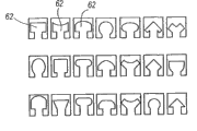
On the one hand, can use various material manufacturing apparatus 10 among the present invention.Slide block 16 is preferably processed by hard relatively material, for example, but is not limited to the combination of duroplasts, rubber, pottery, metal, metal alloy or aforementioned thing.If mating surface 20 and 22 is wanted to make up multiple material.For example, individual other convex 60 can be formed by a kind of material with spill 62, and for example soft rubber is gone up the retaining part of seal 12 and lower seal 14 simultaneously and can be processed by the hard a little material of rubber-like.And last seal 12 and lower seal 14 comprise mating surface 20 and 22, can add metallicity or duroplasts mold insert, and simultaneously, colluding shape and ring-shaped material such as Velcro also can adding apparatus 10.In addition, other various materials for example, but are not limited to gel, silicones, polytetrafluoroethylene (PTFE) fiber, metal or Spiral zipper, lubricant and/or sealant, can use the present invention's one or more compositions in this explanation.
The device of foundation sealing of the present invention has purposes and advantage widely.Usually, this device can be used for outdoor clothes, outdoor gear and container, navigation clothes and equipment, even is used for daily dress ornament.This device need to be specially adapted to the product of complete watertight.This series products comprises; But be not limited to nuisance protective garment, fire-entry suit, dry clothes, dry bag, camping bag, boots, space suit, tent, transportation and packing, family's storage bag, map container, sea chart container, boat skirt, knapsack cover, calculating hood, electronic equipment cover, ship case, aeration vessel (as being used for camera), floating bag, flotation gear, waterproof pocket, fishing vest pocket, Deodorizing bag (as being used to transport) and close-fitting diving dress.Device of the present invention also is specially adapted to need or benefit from windproof product.This series products includes, but are not limited to jacket, sleeping bag, rain gear, boots, boat jacket, windbreaker, Wind proof overcoat and tent.Except waterproof and windproof advantage; Device of the present invention also has other advantage; Comprise; But be not limited to have air-tightness, watertightness, air impermeability, windproof, quiet, be difficult for stumbling or block, (promptly light, inexpensive, not cold) in light weight, nonmetal, recyclable fully, operation be along sliding, cheap and be easy to make.This device has been eliminated the limit and any function that can be used for slide fastener that is used to cover slide fastener, therefore allows many new products to use this device.Special; These new products can comprise following: pull boots, pull dry bag, pull encamp bag, be prone to wear formula boat skirt, waterproof rope bag, waterproof pocket, watertightness or airtight shape transportation and packing fully fully, be prone to the daily camera pouch wearing dry clothes, be used for underwater photographs or film, waterproof and global function knapsack or satchel, pull rain trousers and the rainproof oilcloth of semi-open type fully.
With reference to figure 4, it is the side view that engages into the slide block 16 of seal 12 and lower seal 14.Slide block 16 comprises opening end 36 and closing end 38.When along the arbitrary directions pulling of sealing profile 17 slide block 16, the end of slide block 16 makes the seal closure or openness through profile.More special, opening end 36 is used for separating last seal 12 from lower seal 14.Therefore, when slide block 16 spurs along sealing 17,, just open sealing 17 if spur to closing end 38 from opening end 36.Opposite, the closing end 38 of slide block 16 limits and exerts pressure and makes seal 12 and lower seal 14 interlockings.Like this, when slide block 16 spurs along sealing 17, if spur to opening end 36, with regard to closing seam 17 from closing end 38.In this unlatching and close mechanism, lifting rib applies force to the lifting wing and makes that going up seal draws back from lower seal, and sealing is opened thus.This mechanism be different from directly apply active force in cooperate or contact-making surface form sealing sealing device.
Still with reference to figure 4, pull head 40 preferably uses pin 42 to be installed in the pull head sliding rail 44 along slide block 16 end faces.Sliding in pull head 40 front and back in pull head sliding rail 44, makes slide block 16 have more effective pulling angle, and feasible like this operation slide block 16 is more along sliding with easy.
With reference to figure 5, can see that lifting rib 46 is positioned at the opening end 36 of slide block 16.Lifting rib 46 is provided with respect to 14 pairs of lower seal and goes up the structure that seal 12 applies separating force.
With reference to figure 6, it provides along the profile of the closing end 38 of the slide block 16 of 6-6 line shown in Figure 5.Fig. 6 has described last seal 12 and the layout of lower seal 14 at the closing end 38 of slide block 16.At closing end 38, closure strip 48 embeds the closure strip groove 32 of lower seal 14, and the mating surface 22 of its restriction lower seal 14 is positioned within the main body 50 of slide block 16.The main body 50 of slide block 16 is limited to the closing end 38 of slide block 16, the mating surface 20 of feasible so upward seal 12 and mating surface 22 interlockings of lower seal 14.
The perspective view that Fig. 7 provides slide block 16 to see from the opening end 36 of slide block 16.Opposite, the perspective view that Fig. 8 provides slide block 16 to see from the closing end 38 of slide block 16.Lifting rib 46 as shown in the figure is positioned at the dual-side of slide block 16.Should notice that lifting rib 46 can be along the whole side extension of slide block 16 or only along its part, for example at the first half of opening end 36 along slide block 16.The distance of lifting rib 46 and closure strip 48 at opening end 36 considerably greater than closing end 38 at slide block 16.Clearer and more definite, shown in Figure 7 separating distance S
1Greater than separating distance S shown in Figure 8
2Separating distance S
1Enough separate greatly with the mating surface 20 that will go up seal 12 mating surface 22 from lower seal 14.With reference to figure 5, last seal 12 is clearly explained at the opening end 36 of slide block 16 from the separation of lower seal 14.Opposite, with reference to figure 6, the closing end 38 of slide block 16 makes that going up seal 12 is positioned at interlocking position with lower seal 14.Like this, the opening end 36 of slide block 16 and the distance of closing end 38 are transition regions, go up seal 12 thus and separate with lower seal 14 at opening end 36 like a cork, or go up seal 12 like a cork in closing end 38 and lower seal 14 interlockings.
Assembly of the present invention can be formed various structure.With reference to figure 9a-9o, it has described the last seal 12 at closing end 38 places that are positioned at slide block 16 and the sectional view of lower seal 14.Fig. 9 a explains the width of being longer than the seal profile that closure strip 48 can be suitable.Fig. 9 b has described the various modifications example, and wherein closure strip 48 has moderate-length.With reference to figure 9c, relatively short closure strip 48 has been described, in Fig. 9 d, closure strip 48 is substantially outstanding shape, but still extends in the lower seal 14, although it has insignificant lateral length.Closure strip groove 32 is manufactured on the lower seal 14 in the structure of Fig. 9 a-9d, with the closure strip 48 of holding corresponding size.
With reference to figure 9e, lower seal 14 can form and last seal 12 corresponding various height.Fig. 9 e shows that lower seal 14 can be wrapped on the closure strip 48, and it is raised to the same height with last seal 12 respective surfaces like this.This modification can be used for the slide fastener shape structure near the relatively low profile of sealing 17.
With reference to figure 9f, the terminal point 52 of closure strip 48 can use various end shapes 51.Perhaps, any point (not shown) along closure strip 48 can use simple shape.Fig. 9 f has explained that the semicircle that blocks of similar arrow can be used as the end shape 51 of the terminal point 52 of closure strip 48.Therefore, although do not illustrate, should understand like this, promptly the end shape 51 of terminal point 52 can adopt various ways, includes but not limited to circle, triangle, rectangle, arrow, overhead kick and polyhedron profile.And shown in Fig. 9 g, the terminal point 52 of closure strip 48 can not have any type of additional shape fully.This modification is particularly useful for the situation that closure strip 48 is longer than simple outstanding profile, like this, through its length under mating area, limitation capability and support to the mating area of profile is provided simply.
Fig. 9 h has described the shape of the slide block 16 that is not wrapped in the modification on seal 12 end faces.The slide block 16 of the modification of Fig. 9 h has lifting rib 46, and it extends into the upper surface 47 of the cooperation profile of seal 12.In addition, second lifting rib 46 is along the location, side of slide block 16.Useful is that the lifting rib 46 of the top of the slide block 16 of modification comprises that shape 49 makes lifting rib 46 be anchored in the lifting rib groove 26.Can use the various shapes 49 that are used for lifting rib 46 and corresponding lifting rib groove 26; So that a kind of mechanism to be provided; This mechanism is used for lifting rib 46 is anchored in the upper surface 47 of seal 12, and lifting rib 46 will go up seal 12 at the opening end 36 of slide block 16 and from lower seal 14, pull out like this.
With reference to figure 9i, slide block 16 has single lifting rib 46.Clearer and more definite, the slide block 16 of the modification shown in Fig. 9 i has been used single lifting rib 46, and it extends into the upper surface 47 of the fit shapes 20 of seal 12.Owing to have the slide block shown in Fig. 9 h, the slide block 16 among Fig. 9 i uses shape 49 in the end of single lifting rib 46, and so that a kind of mechanism to be provided, it will be gone up seal 12 and from lower seal 14, pull out when profile is passed the opening end 36 of slide block 16.
Fig. 9 j has explained that above-mentioned combination of features can be used to form slide block/seal combination.Fig. 9 i has explained that slide block 16 has relatively long closure strip 48, and has the side that two lifting rib, 46, the first lifting rib 46 are positioned at slide block 16, and second lifting rib 46 is positioned at along the position of the end face 47 of the main body profile part 25 of last seal 12.And, lower seal 14 be wrapped in the side of slide block 16 and lift certain altitude make lower seal 14 top side face 53 approximately with the height such as top side face of last seal 12.
With reference to figure 9k, show and have columniform slide block 16.This columniform slide block 16 comprises the main body 50 of the closure strip 48 and the outside of the main body profile part 25 that is wrapped in seal 12, and it ends at lifting rib 46.Therefore, the shape of slide block 16 can change and still provide the function of unlatching and closing seam 17 considerably.
With reference to Figure 91, be provided with and strengthen mold insert 54 to strengthen profile of the present invention system.Clearer and more definite, strengthening mold insert 54 through in lower seal 14, comprising, a plurality of enhancing mold inserts 54 can be along the part interval of sealing 17 of the present invention.Mold insert 54 provides firmer hermetically-sealed construction, allows seal to show the characteristic of relative flexible through installing at interval simultaneously.The complete Patent No 5,991,980 that is disclosed in of the interval mounting technique of mold insert, its full content is incorporated herein with for referencial use.
With reference to Figure 91, shown mold insert 54 bending with the big body profile of lower seal 14, wherein lower seal 14 comprises closure strip groove 32.Strengthen the random appearance shape that mold insert 54 can use this paper to explain.For example, shown in Fig. 9 m, slide block 16 has the closure strip 48 that is substantially outstanding shape.Mold insert 54 with lower seal 14 the cardinal principle profile curves, lower seal 14 is lifted certain altitude to cooperate the height of seal 12.Similarly, Fig. 9 n shows the use of mold insert 54, wherein has the slide block 16 that has semi-circular ends shape 51 at terminal point 53 places of its closure strip 48.
With reference to figure 9o, in another aspect of this invention, the rib 56 that can use obturator is to provide the other stability of seal profile.Clearer and more definite, the rib 56 of obturator stretches out from lower seal 14, is used for supporting the structure of main body profile part 25 of the interlocking of seal 12 and lower seal 14.The rib 56 of seal moves or rotates towards lower seal 14 as the major part 25 of the auxiliary upper and lower seal 12,14 that prevents interlocking, and preferably, the rib end 58 outstanding lifting rib grooves 26 that get into of the rib 56 of seal have increased extra stability thus.The rib 56 of obturator can form different shape and can comprise and strengthen mold insert 54.And the rib 56 of seal can be installed at least a portion profile part that covers seal 12 on the (not shown).During use, the closure strip 48 of slide block 16 is passed closure strip groove 32, make the rib 56 of seal towards the deflection of the profile zone of sealing until last seal 12 in lower seal 14 interlockings.When slide block 16 through behind a section of profiles, the rib 56 of seal is got back to the position of supporting the seal profile, shown in Fig. 9 o.
As shown in Figure 3, sealing is that the mating surface 22 through mating surface 20 that makes seal 12 and lower seal 14 contacts interlocking and forms.Mating surface 20 and 22 thereby be to cooperate consistent shape to seal so that two surperficial interlockings form.Each mating surface is formed with spill 62 by at least one or a plurality of convex that is fitted to each other 60.With reference to Figure 10, show various independent protruding fit shapes 60.Shown in figure 10, convex 60 can have the scope of broad.Figure 11 has explained and has cooperated rightly with convex 60 paired spills 62 that its interlocking that has formed spill shown in figure 12 62 and convex 60 is to 64.When forming mating surface 20 and 22, different types of convex 60 can be used on a pair of mating surface 20,22, forming a plurality of shapes with spill 62, as long as each convex 60 matches consistent with corresponding spill 62.Like this, it is right that the convex 60 that changes at relative broad range and the combination of spill 62 can be used to set up the cooperation of unique mating surface 20 and 22.And mating surface 20,22 can comprise the convex 60 and the spill 62 of, two, three or considerable quantity.For example, device 10 can be applied to the medical implant field, and wherein mating surface 20,22 comprises hundreds of or thousands of flanges and groove, convex 60 and the spill 62 perhaps wanted.
With reference to Figure 13, the shape of multiple different complicacy can be used for forming convex 60.Promptly for each convex 60 shown in Figure 10, additional groove or indenture can be formed in these convexs 60.Shown in figure 14, its camber 60 has groove 64, and corresponding spill 62 preferably includes protruding 66 with mating recesses 64.
Except the above complicated shape of mentioning can use, additional shape 68 shown in figure 15 can append to convex 60.Similarly, shown in figure 16, be provided with spill 62, it comprises additional shape 68.During use, opposite mating surface 20 or 22 comprises that suitable sawtooth and groove (not shown) are to be fit to additional shape 68.
With reference to figure 17.1-17.11, be additional aspects of the present invention, it is provided with mating surface 20 and 22, and mating surface comprises the different shape of wanting 70 along the length of convex 60.In order to explain, be shaped as convex 60 shown in all.But, should understand like this, promptly preferably use and can combine the corresponding spill 62 of simple shape 70 to match along its length with convex 60.Figure 17 .1 has shown the top that is positioned at convex 60 and the simple shape 70 of bottom, but does not have shape at the middle part.Shown simple shape is the semicircle that is positioned at each end of convex.But, should understand like this, promptly simple shape 70 can adopt arbitrary shape, for example rectangle, triangle etc.Figure 17 .2 shows the convex 60 that has simple shape 70 at its two ends, top.Figure 17 .3 shows three simple shapes 70 that overlay top of each other along convex length.Figure 17 .4 to 17.9 shows the combination of other several kinds operable possible simple shapes.Can have illustrate here beyond other combination and do not depart from the scope of the present invention.Figure 17 .10 explanation convex 60 can be a curve.In addition, Figure 17 .11 explanation curved male 60 can comprise the simple shape along its length, as is positioned at its end.In a word, convex 60 can comprise that groove 64, additional shape 68, simple shape 70 and/or bool are to constitute mating surface 20,22.Spill 62 fits best convexs 60 and have suitable shapes are as protruding 66, to satisfy the requirement that cooperates convex 60.
Figure 18 a and 18b have explained that last seal 12 and lower seal 14 can comprise respectively along the convex 60 of the differing heights of its mating surface 20 and 22.In a preferred embodiment, designed single mating surface to cooperate himself.Clearer and more definite, single exterior cross-section production, cut and reverse and himself form sealing, like what explain among Figure 18 c to cooperate.Here, single profile is simultaneously as last seal 12 and lower seal 14.
With reference to figure 19-20, shown the modification of first embodiment, the combination of the slide block of wherein revising 16 ' be used for upper and lower seal 12 and 14 seals 17 to set up.Have to slide block 16 ' characteristic closing section 72 and opening section 74.Like slide block 16, the length of slide block 16 ' edge sealing 17 moves with closure or opening encapsulation 17.In the use, when slide block 16 ' edge sealing profile moves the hermetic unit of closing section 72 closed its processes.Opposite, when slide block 16 ' move in opposite direction, opening section 72 is opened the hermetic unit of its processes.
The closure of sealing 17 occurs in closing section 72, because seal 12 is limited in the lower seal 14 on this, thereby makes the mating surface 20 of going up seal 12 be pressed into the mating surface 22 of lower seal 14.More particularly, the mating surface 20 of last seal 12 through slide block 16 ' the part 76 that tilts be pressed into the mating surface 22 of lower seal 14.Simultaneously, lower seal 14 by slide block 16 ' closure strip 48 remain on the appropriate location.
Sloping portion 76 can have horizontal inner surface 78.Yet preferably relatively horizontal plane is downward-sloping or set an angle [alpha] for sloping portion 76.The function of the angle [alpha] that this is downward is when the mating surface 20 of last seal 12 is pressed into the mating surface 22 of lower seal 14, makes seal 12 rotations.The rotation of last seal helps to make that slide block 16 ' moving of sealing 17 is freer drawing back or pulling on.In addition, thereby get into the contact that spill 62 has been improved two surfaces through rotation convex 60, the rotation of last seal 12 has improved the airtight and fire resistance characteristic that is sealed in closure state.Convex 60 and spill 62 are used in the mating surface 20 and 22 of slide block 16 ' sealing, and it comprises groove 64, convexity 66, additional shape 68, simple shape 70 and other previous characteristic of describing that is used for mating surface 20,22 and its combining structure.
With reference to Figure 20, be provided with a series of part cylindrical 80 with the reduction frictional force between part 76 and the last seal 12 that is inclined upwardly.In more detail, it is cylindrical 80 that the inner surface 78 of the part that is inclined upwardly 76 preferably includes the part of some row, and its end face 47 with the main body profile part 25 of last seal 12 contacts.These cylindrical 80 are used for reducing the frictional force that tilts when being inclined upwardly 12 contacts of part 76 and last seal between part 76 and the last seal 12.Part cylindrical 80 also can preferably be used in along be positioned at slide block 16 ' the closure strip of part at least 48 of closing section 72 on.The frictional force that has reduced between closure strip 48 and the lower seal 14 along cylindrical 80 of closure strip 48 inner surfaces 82.
The position of lower seal 14 is stablized and controlled to slide block 16 ' use closure strip 48.Be used to be connected slide block 16 ' on the profile of closure strip 48 can comprise all aforesaid arrangements.Tool is not restricted, and closure strip 48 can be longer relatively, be similar to shown in Fig. 9 a, or it can lack and adopt protruding profile very much, shown in Fig. 9 d.It can comprise that also end shape 51 is to help to catch lower seal 14.Useful especially is to adopt closure strip 48 that is relatively short or outstanding shape.No matter its shape, like slide block 16, the function of closure strip 48 be control lower seal 14 be positioned at slide block 16 '.
Again with reference to Figure 19 and 20, slide block 16 ' the function of opening section 74 be that last seal 12 is separated and opening encapsulations 17 from lower seal 14.Opening section 74 preferably include a lifting rib 46 '.Lifting rib 46 ' be preferably in slide block 16 ' opening section 74 in from about slide block 16 ' the middle part to slide block 16 ' the position of inclination of end extend.Opening section 74 also comprises closure strip 48, its preferably extend to slide block 16 ' the whole length of bottom.Closure strip 48 make lower seal 44 be anchored on slide block 16 ' the bottom.When slide block 16 ' when moving by the opening direction of arrow 84 indications of Figure 19, the lifting rib 46 on the last seal 12 ' with lower seal 14 on the combination action of closure strip 48, spur two seals 12 and separate with 14, opened sealing like this.Be more preferably use one be arranged in slide block 16 ' lifting rib 46 ', rotatablely moving so that seal 12 to be provided from lower seal 14 separation.This rotation be since in the side of main body profile part 25 relative lifting rib 46 ' before near lifting rib 46 ' the side of main body profile part 25 be lifted.The smoothness that this revolving property provides last seal 12 to separate from lower seal 14, and the life-span that helps to improve sealing property are because the frictional force between the upper and lower seal 12 and 14 has reduced when opening.Lifting rib 46 ' can be similar to track or wedge type, shown in figure 20.
With reference to Figure 21, it illustrates illustrative sealing 17 and comprises seal 12 and lower seal 14.The edge that upgrading slot 26 is formed on the main body profile part 25 of seal 12 is positioned at the position under the lifting wing 24.Upgrading slot 26 hold slide block 16 ' lifting rib 46 '.Figure 21 has also explained the closure strip groove 32 in the lower seal 14.
The various hermetically-sealed constructions that Fig. 9 a describes to Fig. 9 o can be fit to use slide block 16 '.In more detail, except the characteristic of having discussed, for example closure strip 48 characteristics and mating surface 20,22 profiles, slide block 16 ' operable replacement structure and characteristic are not limited to shown in Figure 21.For example, slide block 16 ' can add the lifting rib (seeing Fig. 9 i) that single end face is installed, or the lifting rib (seeing Fig. 9 i) of side and end face installation.The part of the last seal 12 beyond the main body profile part 25 can with lower seal 14 equally highly or differing heights.When using 16 ' time of slide block also can on lower seal 14, use enhancing mold insert 54.
With reference to Figure 22 and 23, lifting rib 46 ',, be used for preventing that seal 12 is from lower seal 14 separation through with end 30 excisions of the lifting wing 24 from sealing 17 last seal 12.Owing to lack the lifting wing 24, slide block 161 ' opening section 74 can not catch the downside of seal 12 to make it from lower seal 14 separation.Because the whole length and the lower seal 14 of last seal 12 have been set up fluid barriers, the invention enables sealing 17 when closure, to form.
Figure 24 provide slide block 16 ' from slide block 16 ' preceding or front view that opening section 74 looks.This view further illustrate lifting rib 46 ' from slide block 16 ' the middle part to slide block 16 ' leading section prospect, lift an angle.More preferably, slide block 16 ' in be formed with groove 88 and keep lower seal 14 when helping at opening encapsulation 17.
With reference to Figure 25, provide slide block 16 ' lateral side view.View description the slide block of seeing to closing section 72 16 '.Show again lifting rib 46 ' to slide block 16 ' on lift.
Figure 26 has described same lateral side view shown in Figure 25, but wherein have be arranged in slide block 16 ' last seal 12 and lower seal 14.This view also described be arranged in lifting rib 46 ' on the lifting wing 24 of last seal 12.Closure strip 48 with lower seal 14 be anchored on slide block 16 ' in, and restriction and slide block 16 ' being connected of sloping portion 76 at closing end 38 places, be pressed into the position with mating surface 22 interlockings of lower seal 14 with the mating surface 20 that will go up seal 12.When last seal 12 when the front end of slide block is unlocked, the end face 90 of last seal 12 slide block 16 ' the back on lift.
Contrast Figure 26, Figure 27 have shown the slide block 16 ' front view with last seal 12 and lower seal 14.Here explained slide block 16 ' the function of opening section 74.Slide block 16 ' opening end 36, last seal 12 is drawn back from lower seal 14, thus the bottom surface 92 of exposing seal 12.
In another embodiment; The present invention includes the device that is used for second second limit sealing of first first limit of object and object; Wherein first limit is parallel substantially with second limit with second limit, the second a cardinal principle coplane, and extend with second relative direction on first edge.Said device comprises seal, lower seal, slide block and connector.Last seal is connected with first limit and has first mating surface.Lower seal is connected with second limit and has second mating surface.Second mating surface and first mating surface are the interlockings that locks releasedly.Slide block has main body, slide block internal structure, outer projection and groove part.Main body comprises opening section and closing section, and its closing section has restricted part makes first mating surface of going up seal contact with second mating surface interlocking therein of lower seal.First mating surface of slide block internal structure and last seal and second mating surface of lower seal be cooperation mutually.Connector has connector internal structure, outer projection and groove part.Second mating surface of first mating surface of seal and lower seal cooperation mutually on the connector internal structure.At closing section, connector internal structure and the interlocking of slide block internal structure, and the outer projection of connector and groove part and slide block convexity and groove part interlocking.One direction moves when the slide block edge, and feasible upward seal and lower seal are passed from the opening section to the closing section in slide block, and slide block will limit first mating surface and contact with second mating surface, form sealing like this.
Figure 28-31 has explained the embodiment of sealing device 100.Sealing device 100 comprises seal 12, lower seal 14, slide block 102 and connector 104.Slide block 102 comprises pull head 40, pin 42 and pull head track 44.The sealing device 100 that present embodiment being provided with can lock.Therefore, pull head 40 preferably includes breach 106, and it holds the locking receptacles 108 of latch 104 when slide block 102 is in the close position.In more detail, connector 104 is the permanent stoppers that are fixed in sealing 17 ends.During closing seam 17, slide block 102 is left behind and is gone up the sealing profile 17 of seal 12 and lower seal 1, makes the mating surface 20 of seal 12 and mating surface 22 interlockings of lower seal 14 like this.Slide block 102 arrives its closing position 110 with connector 104, details like hereinafter.Pull head 40 is placed on position forward, makes locking receptacles 108 pass the breach 106 of pull head, thereby guarantees the locking of pull head 40 and locking receptacles 108.Locking receptacles 108 comprises hole 112, and its size can be held common travel lock (not shown).
With reference to Figure 28 and 29, shown to seal two perspective views of 100 again.Figure 28 and 29 has described slide block 102 and has been in its closing position with connector 104, and slide block 102 is set up sealing 17 with connector 104 in sealing profile 110 ends whereby.
Figure 30 is the profile along the 30-30 line intercepting of Figure 28 in last seal 12 sides of sealing device 100.Figure 30 has explained the layout that when slide block 102 and connector 104 are in its closing position 110, goes up seal 12 and lower seal 14.At this, last seal 12 appears with connector 104 shared zones at slide block 102 with lower seal 14 and separates.At this, through the internal structure of slide block 102 and connector 104, last seal 12 has formed the liquids and gases barrier with lower seal 14, like the argumentation of hereinafter.
Figure 31 be sealing device 100 in lower seal 14 sides along the profile of the 31-31 line intercepting of Figure 29.That is, Figure 31 has explained the opposite face of slide block 102/ connector 104 in the cross section that is compared to Figure 30.In Figure 31, lower seal 14 in slide block 102 and connector 104 shared zones, demonstrate from seal 12 separate.
With reference to Figure 32, show the outside and the inner fit structure of connector 104 and slide block 102.Clearer and more definite, connector 104 comprises exterior protrusions and groove part 114, it combines with the exterior protrusions and the groove part 116 of slide block 102 when slide block 102 and connector 104 place its closing position 110.That is, slide block 102 inserts connector 104 along arrow A, makes slide block 102 and connector 104 interlockings.And, the interlocking that matches of internal structure 118 shapes of connector 104 and the mating surface of last seal 12 20 and lower seal 14.Equally, the shape of the internal structure 120 of slide block 102 interlocking that matches with the mating surface 22 of lower seal 104.In addition, the internal structure 118 of connector 104 and internal structure 120 interlockings of slide block 102., slide block 102 and connector 104 form sealing when being in the close position 110; Be because: the mating surface 20 that seal 12 is gone up in (1) forms the fluids sealing with the top 112 of the internal structure 118 of connector 104, and forms the fluids sealing with the top 124 of the internal structure 120 of slide block 102; (2), and form the fluids sealing with the bottom 128 of the internal structure 120 of slide block 102 because the fluids sealing is formed on the bottom 126 of the mating surface of lower seal 14 22 and the internal structure 118 of connector 104.
With reference to figure 31-32, be provided with closed protruding 127 to reduce the friction of going up seal 12 and lower seal 14.In more detail; Closed protruding 127 is preferably cylindrical; When sealing 17 length move, reducing the friction between slide block 102 and last seal 12 and the lower seal 14 at slide block 102, this be because seal 12 with 14 when slide block 102 moves only with protruding tangent contact of closure.
With reference to Figure 33, shown the top view of slide block 102 and connector 104.This view specification the exterior protrusions and the groove part 114 of connector 104, when slide block 102 and connector 104 were positioned at closing position 110, it was connected with groove part 116 with the exterior protrusions of slide block 102.
With reference to Figure 34, front view has shown the internal structure 120 of slide block 102.This view specification the internal structure 120 of slide block 102 form interlockings with the mating surface 22 of mating surface of last seal 12 20 and lower seal 14 respectively.And the support of independent internal structure 120 130 is provided with by angle θ, allows to support the spill 62 of mating surface 22 of spill 62 and lower seal 14 that 130 protruding part is stopped the mating surface 20 of seal 12 like this.Like this, the invention provides stability and the increase of intensity of the internal structure 120 of slide block 102.
Preferably, sealing 100 is used with the shape that various height profile cooperate.That is, preferred, the convex 60 of the mating surface 20 of last seal 12 and the mating surface 22 of lower seal 14 is arranged on differing heights with spill 62.For example, the best profile that the cooperation outer shape shown in Figure 18 c is and sealing 100 is used discharges water when the closing end of slide block 102 35 is closed and windproof when last seal 12 and lower seal 14 helping.
With reference to figure 35-36b with according at least one embodiment of the present invention, be provided with the slide block 16 of modification ", it comprises crooked lifting rib.More particularly, Figure 35 has explained that sealing device 10 comprises seal 12, lower seal 14 and the slide block of revising 16 ", wherein slide block 16 " comprises longitudinal axis L-L.Owing to have a slide block 16 ", slide block 16 " lifting rib 46 " in the zone of the opening section 74 of slide block from slide block 16 " the middle part to be positioned at or near slide block 16 " the position extension of opening end 36.The opening section 74 of slide block regional shown in figure 39.Lifting rib 46 " also curved in length longitudinally between these positions, and more preferably, lifting rib 46 ", from slide block 16 " in first centre position 132 to be positioned at or near slide block 16 " second end position 136 of opening end 36, radially crooked in longitudinal axis L-L.Lifting rib 46 like this " makes progress and curves inwardly.Because at operation slide block 16 " time, shape 60 rotations of mating surface 20 and 22 interlocking, lifting rib 46 " bending slide block 16 is provided " operation along sliding, like this, reduced it and be in contact with one another and the friction of opening when separating in closure.More particularly, lifting rib 46 " mentions the lifting wing 24 of seal 12 and allows to go up seal 12 and peel off from steady rotatably separation of lower seal 14 or orientation.A part of length that the lifting rib 46 of such bending " has a mind to make upper and lower seal 12 and 14 at least along slide block 16 " does not overlap, the contact through rotation convex and spill with separate, the cooperation that more helps providing seal 12 and 14 suitable cunning with separate.And crooked lifting rib 46 " allows less lifting rib to open big width profile, like this, allows to use more compact slide block.
With reference to Figure 37 and 38 and according at least some embodiment of the present invention, sealing device 10 is provided, it comprises slide block 16 " ', it is at slide block 16 " ' the upper inner surface 140 in closing section 72 zones on have fin 144.Closing section 72 zones of slide block are shown in figure 39.Fin 144 is contained in the groove 148 that is positioned at along the end face 90 of last seal 12.Fin 144 helps to keep slide block to remain on the track of seal 12 and 14 with corresponding grooves 148.
With reference to figure 40-43, in the embodiment that separates of the present invention, the sealing device 152 of Endless is provided.More general, according at least one embodiment of the present invention, the closing device of Endless is provided.The closed embodiment of Endless in this detailed description points to the Endless sealing that is used to explain preferred embodiment.Therefore; Shown in figure 40; Endless sealing device 152 comprises seal 156 on the Endless (be similar to the structure of seal 12, but shape being continuous or Endless) and Endless lower seal 160 (be similar to the structure of lower seal 14, but shape being continuous or Endless).The upper and lower seal 156 of Endless and 160 can form the Endless shape through the whole bag of tricks, for example give an example but be not limited to, connect second end of first end of seal 156, perhaps injection mould formation of sealing component 156 or 160 to seal 156.Shown in figure 41, locking hinge slide block 164 is used to engagement and separates Endless seal 156 and 160.According at least one embodiment of the present invention; The structure of locking hinge slide block 164 and other slide block described here is similar; For example slide block 16 " with slide block 16 " ', but preferably include the top of locking releasedly with hinge 168, it allows slider top to lift and put down.Can be familiar with and understand like those skilled in the art; The above-mentioned slider top with hinge 168 of locking releasedly is a kind of openable slide block structure; And the above-mentioned slide block of opening can comprise various structures, and it comprises that the top can remove and reinstall or be fixed tightly in addition on the main body of slide block 164.Like this, have hinge 168 releasedly the locking the top be to be used for slider top is secured to a kind of method on the slide block 164 releasedly.
With reference to embodiments of the invention, slide block 164 can have the curved shape that conforms to substantially with the bending of Endless seal 156,160.As an example but be not limited to, be used for that the slide block that gloves are sealed to the biochemical clothes of sealing can be had the curvature greater than the slide block that is used to seal tent.
With reference to figure 42a, before sealing Endless sealing device 152, seal 156 at first is placed on position close to each other with lower seal 160 on the Endless.The top of locking releasedly with hinge 168 is positioned at the enable possition, and seal 156 moves near the place of slide block 164, aiming at 160 engagements of Endless lower seal substantially, location on the Endless.Shown in Figure 42 b, the top of locking releasedly with hinge 168 rotates to the latched position shown in Figure 42 c, makes interlocking shape 60 engagements of the mating surface 20,22 of Endless seal 156 and 160 like this.Shown in figure 43, slide block 164 advances to form the Endless sealing around Endless seal 156 and 160 borders, and wherein Endless sealing cross section can be circular substantially.Shown in figure 40, Endless seal 156 comprises barbed portion 172, and wherein the lifting wing 24 is removed, and makes the be tightly connected whole border of object of Endless sealing device 152 of slide block 160 like this.
According to embodiments of the invention, can expect that like those skilled in the art Endless sealing 152 has various possible application, includes, but are not limited to: the hand-hole, head-shield, cuff, gloves and/or the boot attachment that are used for chemistry and/or biological protection clothes; The seal of pulling on collar of dry clothes; Tent opening and/or tent interconnect openings; With encapsulation covering, lid and/or sack.
With reference to figure 44a and 44b; With at least one embodiment according to the present invention, be provided with the slide block 176 that uses with last seal and lower seal 12 and 14, wherein; In other used, slide block 176 can be expected to be used for jacket or other clothes or other and have the separable article that draw back the type close mechanism.Therefore, slide block 176 is particularly useful for wherein hoping to have the article of small size slide block.The opening section 74 of slide block 176 separates from closing section 72.More special, for slide block 176, the top 184 and the bottom 192 of slide body 188 fully do not extend into opening section 74.That is, at least one embodiment, the top forward edge 185 at top 184 be positioned at the middle part lateral member 196 leading edge 190 the back or along its vertical rear positions.In addition, at least one embodiment, the bottom front edge 194 of bottom 192 also be positioned at the middle part lateral member 196 leading edge 190 the back or along its vertical rear positions.Like this, according to embodiments of the invention, at least one top forward edge 185 and bottom front edge 194 be positioned at middle part lateral member 196 leading edge 190 the back or along its vertical rear positions.In addition, top forward edge 185 and bottom front edge 194 can be positioned at the position of the leading edge 190 longitudinally-spaced different distance of the lateral member 196 from the middle part.Shown in Figure 44 a and 44b; Top forward edge 185 and bottom front edge 194 preferably be in along the length D of slide block 176 about 10% to 90% between; More preferably be in along the length D of slide block 176 about 30% to 70% between, and more preferably be in along the length D of slide block 176 about 40% to 60% between.Therefore; In at least one embodiment of the present invention; Slide block 176 preferably includes opening section 74, and it has in the top 184 of slide body 188 and the middle part lateral member 196 between the bottom 192, and wherein middle part lateral member 196 is stretched out cantilever from closing section 72 in opening section 74.Middle part lateral member 196 will go up seal 12 when opening encapsulation separates from lower seal 14, plays the effect of chock, and when closing seam, plays the effect of funnel guide rail.Because the result of the structure of slide block 176, seal 12 and 14 is exposed to the front portion 180 of slide block 176
With reference to figure 45a, the about core at slide block 176 as shown in the figure passes vertical plane, and slide block 176 has the circle or the cartouche 198 (dotted line) of evening up a little, and wherein the vertical plane cardinal principle is perpendicular to the longitudinal axis L-L of slide block 176.Because the structure of the cardinal principle balance of slide block 176, this structure has increased the stability of slide block 176.In addition, Figure 45 a has explained that preferably only lateral member 196 side is connected mutually with top 184 along the middle part for the middle part lateral member 196 of slide block 176, and only another side of lateral member 196 is connected mutually with bottom 192 along the middle part.Such structure allows to go up near seal 12 and lower seal 14 position near slide block 176 and stretches to opposite substantially direction.
With reference to figure 45a-45c with according at least one embodiment of the present invention, said middle part lateral member 196 can also comprise the whole of one or more ribs, and if any, preferably the upper and lower surface longitudinal ground of lateral member 196 stretches said rib along the middle part.More specifically, the slide block shown in Figure 45 a-45c 176 for example, the upper surface 204 of last lateral member rib 200 lateral member 196 from the middle part extends, and the lower surface 212 of following lateral member rib 208 lateral member 196 from the middle part extends.According to embodiments of the invention, rib 200,208 can comprise approximate or vertical substantially part, and can also comprise the bending along its longitudinal length.Rib 200,208 can be the continuous opening along its longitudinal length that maybe can comprise.When slide block 176 moved along the length of sealing, rib 200 and 208 help the to align mating surface separately 20,22 of seal 12 and 14 also helped to keep slide block 176 at suitable track.Will be understood that more than one rib can be positioned at middle part lateral member 196 above and/or under surface 204,212.Give an example but be not limited to it, rib is can be respectively consistent with each recessed fit shapes of the mating surface 20,22 of seal 12 and 14.In other interchangeable structure, slide block 176 can not comprise any rib.
With reference to figure 46a, 46b and 47 and according at least one embodiment of the present invention, sealing device 216 have initial limited block, slide block for example slide block 176, go up seal and lower seal 12 and 14.In other was used, sealing device 216 can expect to be used for jacket or other clothes or article, or the article of sleeping bag for example, wherein hoped and can first seal 12 be separated from second seal 14 fully.Also pointed out to be used for the mating surface 20 of seal 12 and 14 and certain material of 22 can allow two seals 12 and 14 to slide relative to each other.Therefore, in order to prevent this slip, can use the initial limited block of locking.
The initial limited block 220 of sealing device 216 is preferably mounted on seal 12 and 14 one, and in a preferred embodiment, said initial limited block 220 is installed on the lower seal 14.Initial limited block comprises the structure with last seal 12 engagements.Give an example but be not limited to it, at least one embodiment of the present invention, initial limited block 220 comprises bias voltage button 224, and it is connected with the projection 228 in the hole that is embedded into the end that is positioned at seal 12 218.During use, slide block 176 is positioned at and is directly adjacent to initial limited block 220 places, goes up the front portion 180 that seal 12 slides into slide block 176 then, and anterior 180 help seal 12 to get into initial limited block 220.Projection 228 then embeds the hole 218 of going up in the seal 12, locks onto releasedly in the initial limited block 220 will go up seal.The bottom of projection 228 preferably includes inclined surface 222 with along sliding ground embedded hole 218, wherein inclined surface 222 preferably from the front portion of projection 228 to rear portion tilt (or from left to right shown in figure 47).After in last seal 12 is locked onto initial limited block 220 releasedly, slide block 176 moves to seal at seal 12 and 14 formation along mating surface 20,22 length.When opening sealing; Slide block 176 moves up to the rear portion 186 of slide block 176 to initial limited block 220 and is near initial limited block 220 places; The rear portion of button 224 is depressed with pulling out in the hole 218 of projection 228 from last seal 12 then, makes that like this going up seal 12 skids off from initial limited block 220 and slide block 176.
With reference to figure 48a-48g with according to alternative embodiment of the present invention, provide sealing device 216 ', said device have initial limited block 220 ', its device with replacement inserts seal 12 in initial limited block 220 ' middle back support at last seal 12.More special; With aforesaid; The initial limited block 220 that uses the hole 218 on the seal in the utilization of bias voltage projection to lock seal is compared, initial limited block 220 ' preferably include clamp or tension on seal 12 will go up the mechanism of seal and initial limited block 220 ' keep together.
Figure 48 a explained initial limited block 220 ' and near initial limited block 220 ' slide block 232.Seal 12 passes slide block 232 fronts 180 and is inserted into the typical action of doing when using common slide fastener as the user in said initial limited block 220 ' permission.Yet; Substitute the said engagement one little engagement protrusion that is used for aforementioned initial limited block; Through with the releasable device that tightens up or clamp of initial limited block 220 ' operative association, will go up seal 12 and remain on the appropriate location, such clamping device comprises; But be not limited to a series of clip or the thin slice 236 of catching profile.As it may occur to persons skilled in the art that, can there be a lot of shape and size options to be used for thin slice 236, comprise one or more structure example such as bias voltage projection, tip and coarse surface, like convexity and/or sand paper class surface.Usually, clip or thin slice can be any things of catching seal 12 and holding it in the appropriate location.As the replacement the device of catching seal, can use little finger of toe pump (small finger pump) set up vacuum with last seal 12 remain on initial limited block 220 ' on.Alternative, be used for method promptly and comprise one or more magnet.Possible like this structure comprise the end that is connected to seal 12 or with little feeromagnetic metal of its all-in-one-piece or magnet iron piece; The magnetic function spare that replenishes simultaneously is positioned at initial limited block 220 ' inboard or operative association in its inboard, and wherein magnetic force is enough to last seal 12 is kept in position.
With reference to figure 49-52, and according at least one embodiment of the present invention, provide the sealing device of running away to be used to allow the article that the user withdraws from fast.Have such situation, for example, the soldier sleeps has the enemy to threaten when their sleeping bag or other emergency appearance.Under the circumstances of sd so, need not seek the pull head of slide fastener and leave fast, the soldier can withdraw from sleeping bag fast like this.The sealing device 240 of running away provides the encapsulating method that is used to seal sleeping bag 244, and also allows the soldier when situation needs, to withdraw from sleeping bag fast.
The sealing device 240 of running away preferably uses independent block slide block, and for example aforesaid slide block 176 wherein preferably includes the one or more opposite side of lateral member 196 extends from the middle part last lateral member rib 200 and following lateral member ribs 208.In addition, in one embodiment, the sealing device 240 of running away also comprises the last seal 12 of lacking than lower seal 14 a little, and is perhaps interchangeable, on last seal 12, exists enough breach to hold slide block 176.For such structure, slide block 176 can, the part of cutting away or near the breach of seal 12, separate from last seal 12 fully.Can understand like this is that slide block 176 can alternatively separate from lower seal 14.This realizes than last seal 12 short lower seal 14 through being provided with one, or has the lower seal 14 that is similar to cut-out that is used for seal described here or breach through setting and realize.Be to explain the purpose of preferred embodiment, point to the slide block 176 that separates from last seal 12 in the example of this explanation.Shown in Figure 52, when slide block 176 separates from last seal 12, the user can force seal 12 to separate with lower seal 14 and also withdraw from sleeping bag 244 fast.
During use, the user of the sealing device 240 of running away can at first will go up seal 12 and get into slide block 176 with closed its sleeping bag 244 in the bottom 248 of sleeping bag 244.Allow user's closed its sleeping bag 244 to the top of sleeping bag 244 252 moving sliders 176 time like this.Figure 50 has explained the correspondence excision at the top 252 that is positioned at sleeping bag 244 or the slide block 176 of the position of the last seal that shortens.Shown in Figure 51, slide block 176 surpasses the end of last seal 12 forward, and like this, slide block 176 only cooperates lower seal 14.Shown in Figure 52, the user can promote the upper strata of sleeping bag, and last seal 12 will separate (using suitable strength) from lower seal 14, thereby allow the user to withdraw from sleeping bag 244 fast and needn't use slide block 176.When returning sleeping bag, the bottom 248 that the user can be along lower seal 14 moving sliders 176 to sleeping bag will be gone up seal 12 and got into slide blocks 176, from and sleeping bag is closed.
For the sleeping bag 240 of running away, in case slide block 176 extends beyond and when last seal 12 separated, one or more upper and lower lateral member ribs 200 and 208 helped slide block 176 is remained on the track of lower seal 14.
According to embodiments of the invention with shown in Figure 50-52, upper and lower seal 12 and 14 corresponding mating surfaces 20 and 22 preferably include the fit shapes with hourglass configuration.The hourglass shape matching surface provides mating surface 20, the suitable contact surface between 22 to amass; Thereby provide along the air-tightness and the watertightness sealing of the length of seal; And provide enough shear strength when using usually, keeping the closure of seal, but allow the user to open seal again with the separating force of fair-sized.As it may occur to persons skilled in the art that, should understand like this and promptly can use one or more shapes and combination thereof and be included in the category of the present invention.
With reference to Figure 53 and 54; And according to embodiments of the invention; Shown the last seal 12 with lower seal 14 interlockings, wherein seal 12 is identical with two mating surfaces 20 of 14 with 22, and thereby can produce single seal and simultaneously as upper and lower seal.With reference to Figure 53, mating surface 20 and 22 comprises the convex 460 of hourglass shape and the convex 464 of mushroom-shaped simultaneously.In addition, combination convex 468 comprises hourglass shape side and mushroom-shaped side.Convex 460,464 and 468 provides certain usefulness when using separately and make up use, shown in Figure 53.More particularly, the combination of convex (with corresponding spill) is novel, be because: (1) is formed with hourglass shape convex 460 so that enough sealings to be provided, and has stoped the intrusion of some gas like this; (2) convex 464 of mushroom-shaped provides suitable cooperation (or interlocking) intensity, also has circle (surface area is big like this) top simultaneously so that the performance of anti-preferably gas and water to be provided.Combination convex 468 allows the integration of adjacent hourglass shape convex 460 and mushroom-shaped convex 464, to interlocking intensity and anti-current body animal migration contribution is provided again simultaneously.
With reference to Figure 54, upper and lower seal 12 and 14 all comprises the mating surface that only has mushroom-shaped convex 464, and the enough interlocking intensity of seal is provided thus.
With reference to Figure 55 with according to embodiments of the invention, one or more seals 12 and 14 can comprise that material different is to provide structure and migration performance characteristics preferably.As an example rather than restriction, two or more materials with different hardness can be in order to form the part of seal 12 and 14, the for example part shown in Figure 55 472.Such seal can use the coextrusion processing technology to form.Should understand like this be said convex can also comprise and the adjacent part material different of seal.For example, hourglass shape convex 460 can comprise the low material of mushroom-shaped convex 464 hardness than adjacent co-extrusion modling.
With reference to figure 56-58 with according at least one embodiment of the present invention, be provided with double track system 400, wherein dual lower seal 414 comprises two cover mating surface 422a and 422b, and wherein the first mating surface 422a and the second mating surface 422b are spaced apart.Said double track system 400 provides the advantage that allows to have with single production stage production the lower seal of two mating surfaces.This provides the production cost advantage of the sealing device that is used for certain article.As an example rather than restriction, many jackets comprise that the zip mode lining makes and other lining, can the person of being used be added on the jacket so that more warmth retention properties to be provided like wool layer.In another embodiment, sleeping bag can comprise the ability that supplies the user to pull on the camping bag.Through the double track system is provided, article can hang down material cost, weight and volume and made.
Shown in Figure 56, be sealed to the first mating surface 422a of dual lower seal 414 through mating surface 420a with seal 412a on first, double track system 400 allows that seal 412a is connected to dual lower seal 414 on first.In addition, be sealed to the second mating surface 422b of dual lower seal 414 through the mating surface 420b with seal 412b on second, double track system 400 allows the second seal 412b to be connected to dual lower seal 414.
Be to be understood that to be that various sealing device described here can use one or more aforesaid any mating surface and protruding/concave shapes, and/or its combination, and such use and possible combination are all within category of the present invention.
Should note described word " " or refer to one or more entities.Same, word " " " one or many " and " at least one " can use in this exchange.Should also be noted that word " comprises ", " comprising " and " having " can exchange use.
Though above description and accompanying drawing are open and various alternative embodiment have been described, should understand like this, the present invention is not limited to these embodiment certainly.The technical staff in the field under the present invention can make other modification and use the embodiment of principle of the present invention, especially teaches according to the front.Therefore, through appended claims, the applicant wants to contain all modifications example and other embodiment.
The present invention has comprised member, method, process, system and/or equipment in various embodiments, and as described herein, the present invention also comprises various embodiment, sub-combinations thereof and its subclass substantially.Can know how to make and use the present invention after it will be apparent to those skilled in the art that the disclosure.The present invention comprises generator and process in various embodiments; It can lack herein or its various embodiment in the undeclared and/or details described; It can lack the device that has been used in formerly or the details of process, for example is used to improve performance or realizes easily and/or reduce the details of implementation cost.
Aforesaid discussion of the present invention is used for explanation and purpose of description.Aforementioned a certain form or the form disclosed herein of it be not intended to limit the invention to.In aforementioned detailed description, for example, from simplifying this illustrative purposes, various characteristics of the present invention are included into one or more embodiment.This illustration method can not be considered to reflect such intention, i.e. the present invention need be more than the clear characteristics of enumerating in every claim.Certainly, like that claims reflect enclosed, have the aspect of invention to be less than all characteristics of the embodiment of single above stated specification.Like this, appended claim is incorporated in the detailed description of the present invention, and wherein each claim is based on himself, and it is taken as independently preferred embodiment of the present invention.
And; Although specification of the present invention has comprised that one or more embodiment and some change and the explanation of modification; Other variation and modification still belong within the category of the present invention, for example, still belong to technology and the knowledge of those skilled in the art after understanding the present invention.In allowed limits; Go for the rights protection that comprises alternative embodiment; Alternative, interchangeable and/or suitable structure, function, scope or the step that comprise claim; No matter whether these alternative, interchangeable and/or suitable structures, function, scope or step be open at this, and be not to want openly to be limited to any patentability theme.
Claims (12)
1. one kind forms the device that Endless seals, and comprising:
(a) has seal on the Endless of first mating surface;
(b) has the Endless lower seal of second mating surface, wherein said second mating surface and the said first mating surface interlocking; With
(c) has the slide block at the top of locking releasedly; Said slide block is used for said first mating surface is locked onto said second mating surface, and wherein this top that locks releasedly allows this top-lifting that locks releasedly of slide block and puts down so that the said top of locking releasedly lays respectively at first enable possition and second latched position;
Wherein, When said releasedly when the top of locking is positioned at said first enable possition; Can be positioned at the position on the said Endless lower seal of at least a portion at seal on the said Endless of said slide block place at least a portion; Wherein when said releasedly when the top of locking is positioned at said second latched position; Said slide block makes states on the Endless seal engages to said Endless lower seal in said slide block place, and said slide block can move along seal on the said Endless and said Endless lower seal, makes the engagement of said first mating surface and said second mating surface to form the Endless sealing.
2. device according to claim 1 is characterized in that, at least one of seal and said Endless lower seal is made up of the material of two kinds of different hardness at least on the said Endless.
3. device according to claim 1 is characterized in that, a kind of below wherein said first mating surface and the said second mating surface both comprise at least: (a) combination convex, and it has first side and second side that is roughly mushroom-shaped of the hourglass shape of being roughly; (b) at least one hourglass shape convex.
4. device according to claim 1 is characterized in that, the cross section of said Endless sealing is a circle roughly.
5. product that comprises device as claimed in claim 1; It is characterized in that; Said product is from the group that following product is formed, to select: nuisance protective garment, fire-entry suit, dry clothes, dry bag, body bag, camping bag, space suit, tent, transportation and packing, family's storage bag, map container, boat skirt, knapsack cover, electronic equipment cover, ship case, aeration vessel, flotation gear, waterproof pocket, fishing vest pocket, Deodorizing bag, close-fitting diving dress, jacket, sleeping bag, rain gear, boots, windbreaker, Wind proof overcoat.
6. device according to claim 1 is characterized in that seal has the lifting wing on the said Endless, and said Endless lower seal has the closure strip groove, and said slide block comprises:
(i) the said lifting wing slip of seal movingly on the lifting rib, itself and said Endless;
(ii) closure strip, the said closure strip groove of itself and said Endless lower seal is slidingly matched;
The main body that (iii) has closing end and opening end, lifting rib described in the said closing end are closed near said closure strip, and lifting rib described in the said opening end is open near said closure strip;
Wherein said slide block can slide so that said upward seal and said lower seal said opening end from said slide block in said slide block pass through to said closing end along seal on the said Endless and said Endless lower seal; Said slide block can slide into terminal position from the starting position along seal and said lower seal on one section said Endless, and wherein said terminal position is positioned at said starting position; Perhaps near said starting position;
Wherein slide block makes the engagement that contacts with said second mating surface of said first mating surface, forms said Endless sealing thus.
7. device according to claim 6; It is characterized in that; The said top of locking releasedly has inner surface; Said inner surface comprises fin, and the groove fit of the upper surface of seal on itself and the said Endless is so that at said slide block auxiliary suitable aligning of slide block that keeps when seal moves on the said Endless.
8. device according to claim 6 is characterized in that, the said main body of said slide block comprises that part is cylindrical, its be arranged in said Endless on seal and said at least one position contacting of Endless lower seal.
9. device according to claim 6 is characterized in that seal comprises barbed portion on the said Endless, does not wherein have the said lifting wing.
10. product that comprises device as claimed in claim 6; It is characterized in that; Said product is from the group that following product is formed, to select: nuisance protective garment, fire-entry suit, dry clothes, dry bag, body bag, camping bag, space suit, tent, transportation and packing, family's storage bag, map container, boat skirt, knapsack cover, electronic equipment cover, ship case, aeration vessel, floating bag, flotation gear, waterproof pocket, fishing vest pocket, Deodorizing bag, close-fitting diving dress, jacket, sleeping bag, rain gear, boots, windbreaker, Wind proof overcoat.
11. one kind comprises like the product of claim 1 or 6 described devices, it is characterized in that, said product is from the group that following product is formed, to select: waders, sea chart container, calculating hood, floating bag and boat jacket.
12. device according to claim 1 is characterized in that, seal and said Endless lower seal are (a) anti-gas transfer seal on the said Endless; (b) gastight seal; (c) anti-watertight seal; (d) waterproof seal; (e) the permeable seal of fluid; The perhaps permeable seal of (f) gas.
Applications Claiming Priority (2)
| Application Number | Priority Date | Filing Date | Title |
|---|---|---|---|
| US62219104P | 2004-10-25 | 2004-10-25 | |
| US60/622,191 | 2004-10-25 |
Related Parent Applications (1)
| Application Number | Title | Priority Date | Filing Date |
|---|---|---|---|
| CN2005800437807A Division CN101102693B (en) | 2004-10-25 | 2005-10-25 | Device for creating a seal between fabrics or other materials |
Publications (2)
| Publication Number | Publication Date |
|---|---|
| CN101589868A CN101589868A (en) | 2009-12-02 |
| CN101589868B true CN101589868B (en) | 2012-02-15 |
Family
ID=36228466
Family Applications (5)
| Application Number | Title | Priority Date | Filing Date |
|---|---|---|---|
| CN2011102043883A Pending CN102247039A (en) | 2004-10-25 | 2005-10-25 | Device for forming a seal and product including the same |
| CN2011102046665A Pending CN102232676A (en) | 2004-10-25 | 2005-10-25 | Breakout sealing device and product including same |
| CN2008101748476A Expired - Fee Related CN101589868B (en) | 2004-10-25 | 2005-10-25 | Device for creating a seal between fabrics or other materials |
| CN2010102733032A Pending CN101972067A (en) | 2004-10-25 | 2005-10-25 | Device for creating a seal between fabric and other materials |
| CN2005800437807A Expired - Fee Related CN101102693B (en) | 2004-10-25 | 2005-10-25 | Device for creating a seal between fabrics or other materials |
Family Applications Before (2)
| Application Number | Title | Priority Date | Filing Date |
|---|---|---|---|
| CN2011102043883A Pending CN102247039A (en) | 2004-10-25 | 2005-10-25 | Device for forming a seal and product including the same |
| CN2011102046665A Pending CN102232676A (en) | 2004-10-25 | 2005-10-25 | Breakout sealing device and product including same |
Family Applications After (2)
| Application Number | Title | Priority Date | Filing Date |
|---|---|---|---|
| CN2010102733032A Pending CN101972067A (en) | 2004-10-25 | 2005-10-25 | Device for creating a seal between fabric and other materials |
| CN2005800437807A Expired - Fee Related CN101102693B (en) | 2004-10-25 | 2005-10-25 | Device for creating a seal between fabrics or other materials |
Country Status (8)
| Country | Link |
|---|---|
| US (1) | US7574780B2 (en) |
| EP (1) | EP1804604B1 (en) |
| JP (1) | JP5039556B2 (en) |
| KR (1) | KR20070088650A (en) |
| CN (5) | CN102247039A (en) |
| AT (1) | ATE540591T1 (en) |
| CA (1) | CA2585130A1 (en) |
| WO (1) | WO2006047655A2 (en) |
Families Citing this family (35)
| Publication number | Priority date | Publication date | Assignee | Title |
|---|---|---|---|---|
| EP2106715A3 (en) * | 2001-04-30 | 2010-03-17 | Gore Enterprise Holdings, Inc. | Device for creating a seal between fabrics or other materials |
| GB0506680D0 (en) | 2005-04-01 | 2005-05-11 | Ykk Europ Ltd | A readily burstable slide fastener |
| WO2006103438A1 (en) * | 2005-04-01 | 2006-10-05 | Ykk Corporation | A readily burstable slide fastener |
| US20090276985A1 (en) * | 2006-06-26 | 2009-11-12 | Kwang Bae Kim | Zipper Knob |
| WO2008003002A2 (en) * | 2006-06-28 | 2008-01-03 | W.L. Gore & Associates, Inc. | Device for creating a seal between fabrics or other materials |
| CN2933077Y (en) * | 2006-06-30 | 2007-08-15 | 西华企业股份有限公司 | Sealing type zipper head structure |
| CA2670108C (en) * | 2006-11-19 | 2013-04-16 | W.L. Gore & Associates, Inc. | Devices and methods for forming a closure between fabrics and/or other materials |
| US20100175230A1 (en) * | 2006-11-19 | 2010-07-15 | Kelsey William D | Locking Mechanisms For Use With Devices For Forming A Closure Between Materials |
| US20080271298A1 (en) * | 2007-01-11 | 2008-11-06 | Benjamin Meager | Device for creating a seal between fabrics and/or other materials and methods of making and using the same |
| CA2700166A1 (en) * | 2007-09-25 | 2009-04-02 | Gore Enterprise Holdings, Inc. | Self-lubricating fasteners |
| KR100943304B1 (en) * | 2007-12-06 | 2010-02-23 | 이상철 | Watertight zipper |
| US20100314839A1 (en) * | 2009-06-15 | 2010-12-16 | Rudo Enserink | Replaceable water tight seal |
| PL2528830T3 (en) | 2010-01-28 | 2014-08-29 | Avery Dennison Corp | Label applicator belt system |
| US8087826B1 (en) | 2010-06-25 | 2012-01-03 | Pactiv Corporation | Slider track with improved seal strength |
| CN101884456B (en) * | 2010-07-15 | 2012-02-29 | 张卫 | Sucker type zipper |
| NO20101288A1 (en) * | 2010-09-15 | 2012-02-27 | Rottefella As | Assembly for connecting a boot to a ski, as well as an adapter for use in said assembly |
| KR101103652B1 (en) | 2011-04-19 | 2012-01-11 | 강희숙 | Waterproof zipper |
| KR101311948B1 (en) | 2012-05-08 | 2013-10-14 | 차민호 | Waterproof zipper |
| CN103292070A (en) * | 2013-06-08 | 2013-09-11 | 中国农业科学院农田灌溉研究所 | Zipper-type water delivery flexible pipe |
| CN103315459A (en) * | 2013-07-01 | 2013-09-25 | 垦青(浙江)拉链有限公司 | Waterproof zipper |
| ITGE20130083A1 (en) * | 2013-08-21 | 2015-02-22 | Mares Spa | REVERSIBLE CONNECTING DEVICE FOR A HANDSET POCKET WITH A POCKET OF A DIVING JACKET |
| KR101427539B1 (en) * | 2013-12-05 | 2014-08-07 | 윤해광 | zipper with subsidiary zipper |
| US9591897B2 (en) * | 2014-07-23 | 2017-03-14 | Ykk Corporation | Slide fastener with angled elements |
| WO2016120500A1 (en) * | 2015-01-29 | 2016-08-04 | Medi Care System, Slu | Safety device for belts |
| CN105342081A (en) * | 2015-11-20 | 2016-02-24 | 温州市自强塑胶夹链有限公司 | Zipper |
| US9717310B1 (en) | 2016-01-27 | 2017-08-01 | Roger C. Y. Chung | Waterproof open-end zipper |
| TR201809604T4 (en) | 2016-01-29 | 2018-07-23 | C Y Chung Roger | Waterproof open end zipper. |
| JP2017144030A (en) * | 2016-02-17 | 2017-08-24 | 俊彦 鍾 | Waterproof fastener |
| US10076145B2 (en) * | 2016-03-18 | 2018-09-18 | Steven J. HARRELL | Clamping device |
| DE102016108288A1 (en) * | 2016-05-04 | 2017-11-09 | Recaro Aircraft Seating Gmbh & Co. Kg | Rescue pocket |
| US10085524B2 (en) * | 2016-07-25 | 2018-10-02 | Jeffery William Thomas Fleming | Hook and loop fastener |
| GB2596589A (en) * | 2020-07-03 | 2022-01-05 | Ykk Europe Ltd | Slide fastener |
| US11827420B2 (en) * | 2021-03-25 | 2023-11-28 | Shinsung Silicone Co., Ltd. | Silicone zipper bag |
| CN112993626A (en) * | 2021-03-25 | 2021-06-18 | 中国电力科学研究院有限公司 | Conductive connecting device and live-wire work shielding clothes |
| CN215206411U (en) * | 2021-07-15 | 2021-12-17 | 深圳市松信硅胶制品有限公司 | Vacuum silica gel bag |
Citations (4)
| Publication number | Priority date | Publication date | Assignee | Title |
|---|---|---|---|---|
| US2810944A (en) * | 1952-06-16 | 1957-10-29 | Giovanni Mastracchi Manes | Water and gas-tight sliding clasp fastener |
| CN1395474A (en) * | 2000-01-11 | 2003-02-05 | 宝洁公司 | Slider for reclosable fastener lying a two dimensional plane |
| US6558037B2 (en) * | 2000-07-27 | 2003-05-06 | Evoluzione S.R.L. | Flexible self-standing bag |
| CN1514693A (en) * | 2001-04-30 | 2004-07-21 | M | Device for creating seal between fabrics or materials |
Family Cites Families (101)
| Publication number | Priority date | Publication date | Assignee | Title |
|---|---|---|---|---|
| BE514547A (en) | ||||
| US1706097A (en) | 1927-02-23 | 1929-03-19 | Aud Company Inc | Life-saving suit |
| US1703712A (en) | 1927-04-15 | 1929-02-26 | Aud Thomas Edgar | Closure for containers |
| US1959319A (en) | 1927-07-16 | 1934-05-15 | Hookless Fastener Co | Fastening device |
| US1719856A (en) | 1927-07-18 | 1929-07-09 | Harry E Sipe | Fastening device |
| US1959318A (en) | 1927-09-22 | 1934-05-15 | Hookless Fastener Co | Separable fastener |
| US1887741A (en) | 1927-11-22 | 1932-11-15 | Hookless Fastener Co | Fastening device |
| FR812476A (en) | 1935-10-24 | 1937-05-11 | Process for the manufacture of slide closures and means for its implementation | |
| US2263481A (en) | 1939-02-10 | 1941-11-18 | Austin Ben Ragan | Zipper fastener |
| US2355816A (en) | 1939-09-13 | 1944-08-15 | Morner Hans Georg | Closure |
| US2353858A (en) | 1943-02-16 | 1944-07-18 | John T Tedesco | Slide fastener |
| US2506965A (en) * | 1944-02-16 | 1950-05-09 | Louis H Morin | Slider check for separable fasteners |
| US2491524A (en) | 1945-06-27 | 1949-12-20 | Paul A Siple | Fastener operating means |
| US2507445A (en) | 1945-07-26 | 1950-05-09 | Derby Sealers Inc | Tape-serving mechanism |
| US2652611A (en) | 1950-01-02 | 1953-09-22 | Jaster Erich Hermann Ernst | Separable slide fastener |
| CH287845A (en) | 1950-08-18 | 1952-12-31 | Polyplast B Wurm & Co | Zipper. |
| US2613421A (en) * | 1951-01-27 | 1952-10-14 | Flexico U S A S A | Slide fastener |
| US2696032A (en) | 1951-07-03 | 1954-12-07 | Giovanni Mastracchi Manes | Sliding clasp fastener |
| US2665467A (en) | 1951-09-05 | 1954-01-12 | Firestone Tire & Rubber Co | Fastening device |
| US2777181A (en) | 1951-09-15 | 1957-01-15 | Morner Hans George | Waterproof closure |
| US2797463A (en) | 1953-03-12 | 1957-07-02 | Talon Inc | Extruded fastener |
| US2794227A (en) | 1953-04-28 | 1957-06-04 | Talon Inc | Separating end for extruded fastener |
| US2909822A (en) | 1954-09-10 | 1959-10-27 | Botti Argentino Benjamin | Continuous linear closing devices |
| US2889605A (en) | 1955-02-21 | 1959-06-09 | Louis H Morin | Duplex separable fasteners for uniting multiple members |
| US2869207A (en) | 1956-01-20 | 1959-01-20 | Beverly Dev Corp | Slide fastener |
| US2871539A (en) | 1956-05-22 | 1959-02-03 | Talon Inc | Extruded fastener |
| US2941027A (en) | 1957-09-10 | 1960-06-14 | Flexigrip Inc | Method and means for protectively encasing wires |
| US2978769A (en) | 1958-07-07 | 1961-04-11 | Talon Inc | Plastic bag or container |
| US3153269A (en) | 1962-06-21 | 1964-10-20 | Smyth Roston & Pavitt | Slide fastener |
| US3203062A (en) | 1962-09-07 | 1965-08-31 | Ausnit Steven | Double hinged fastener |
| US3203602A (en) * | 1963-06-05 | 1965-08-31 | Union Tank Car Co | Line pressure operated metering device for water conditioning system |
| DE1435791A1 (en) | 1963-11-23 | 1969-02-20 | Jaster Geb Krupska Margarete J | Packaging or sheathing made of plastic |
| US3266112A (en) * | 1964-05-14 | 1966-08-16 | Thomas P Heckman | Permanent magnet fastener |
| US3309746A (en) | 1964-05-26 | 1967-03-21 | Talon Inc | End stops |
| US3259951A (en) | 1964-07-15 | 1966-07-12 | Merle A Zimmerman | Slide fastener |
| US3325084A (en) | 1965-10-18 | 1967-06-13 | Ausnit Steven | Pressure closable fastener |
| US3490109A (en) | 1966-07-06 | 1970-01-20 | Opti Holding Ag | Fluidtight slide fastener |
| FR1529652A (en) | 1967-03-07 | 1968-06-21 | Slider for closing bags made up of complementary profiled strips | |
| GB1211579A (en) | 1968-02-01 | 1970-11-11 | E P S Res & Dev Ltd | Improvements in or relating to strip fasteners |
| GB1213698A (en) | 1968-04-29 | 1970-11-25 | English Numbering Machines | Apparatus for orientating channelled objects |
| US3591914A (en) | 1969-04-21 | 1971-07-13 | Opti Holding Ag | Method and apparatus for making fluidtight slide fastener |
| CA1003615A (en) | 1971-12-29 | 1977-01-18 | Union Carbide Corporation | Bristled article and process |
| US3914827A (en) | 1973-12-18 | 1975-10-28 | Michael A Brown | Waterproof slide fastener |
| US3959856A (en) | 1975-03-06 | 1976-06-01 | Steven Ausnit | Interlocking separable fastener |
| US4137608A (en) | 1977-10-11 | 1979-02-06 | Textron Inc. | Slide fastener with adjustable stop |
| US4199845A (en) | 1978-02-08 | 1980-04-29 | Minigrip, Inc. | Slider for heavy duty flexible fastener tracks |
| DE2961493D1 (en) | 1978-03-09 | 1982-01-28 | Bud Hans | Sliding clasp for mating strips and method for mounting said sliding clasp on said mating strips |
| GB2180591B (en) | 1985-09-18 | 1989-04-26 | James Trevor Jones | End terminating means for slide fasteners |
| GB8703439D0 (en) | 1987-02-13 | 1987-03-18 | Clark D F | Slide fasteners |
| US4929487A (en) * | 1987-09-14 | 1990-05-29 | Minigrip, Inc. | Bag making material having fastener profiles and alignment ribs with reinforcing and stabilizing beam effect ridge means |
| US5062186A (en) | 1987-11-09 | 1991-11-05 | The United States Of America As Represented By The United States Department Of Energy | Quick-sealing design for radiological containment |
| KR900005050Y1 (en) | 1988-01-18 | 1990-06-08 | 김삼홍 | Slide fastener having a lock and seperating device |
| US4890935A (en) | 1988-08-16 | 1990-01-02 | Minigrip, Inc. | Leak resistant zipper |
| US4905694A (en) | 1989-04-04 | 1990-03-06 | Ethicon, Inc. | Intracorporeal temporary wound closure |
| JPH03182202A (en) | 1989-12-12 | 1991-08-08 | Yoshida Kogyo Kk <Ykk> | Slide fastener and manufacture thereof |
| US5070583A (en) | 1990-03-07 | 1991-12-10 | Mobil Oil Corporation | Gull wing zipper slider |
| US5010627A (en) | 1990-03-07 | 1991-04-30 | Mobil Oil Corporation | Foldable plastic slider and method of assembly with a plastic reclosable fastener |
| US5007143A (en) | 1990-03-07 | 1991-04-16 | Mobil Oil Corp. | Rolling action zipper profile and slipper therefor |
| US5007142A (en) | 1990-03-07 | 1991-04-16 | Mobil Oil Corp. | Method of assembling a snapped-together multipart plastic slider with a plastic reclosable fastener |
| US5756061A (en) * | 1990-11-13 | 1998-05-26 | White; John L. | Diamond synthesis from silicon carbide |
| US5161286A (en) | 1991-03-22 | 1992-11-10 | Mobil Oil Corporation | End clamp stops for plastic reclosable fastener |
| US5067208A (en) | 1991-03-22 | 1991-11-26 | Mobil Oil Corporation | Plastic reclosable fastener with self-locking slider |
| US5152613A (en) | 1991-03-22 | 1992-10-06 | Mobil Oil Corporation | Plastic film zipper bag having straightened heat seals |
| GB9115068D0 (en) * | 1991-07-12 | 1991-08-28 | Clark David F | Closure for slide fasteners and the like |
| JPH05294352A (en) | 1992-04-17 | 1993-11-09 | Idemitsu Petrochem Co Ltd | Interlocking device and packaging bag fitted therewith |
| US5253395A (en) | 1992-06-26 | 1993-10-19 | Yoshida Kogyo K. K. | Watertight slide fastener |
| JPH0678809A (en) | 1992-08-31 | 1994-03-22 | Yoshida Kogyo Kk <Ykk> | Automatic finishing method for airtight sealing and waterproofing |
| US5283932A (en) | 1993-06-10 | 1994-02-08 | Mobil Oil Corporation | Flexible plastic zipper slider with rigidizing structure for assembly with profiled plastic zipper |
| US5397182A (en) | 1993-10-13 | 1995-03-14 | Reynolds Consumer Products Inc. | Write-on profile strips for recloseable plastic storage bags |
| US5412924A (en) | 1994-04-11 | 1995-05-09 | Minigrip, Inc. | Method of making reclosable plastic bags on a form, fill and seal machine |
| US5553339A (en) * | 1995-02-24 | 1996-09-10 | Thomas; Roy C. | Adjustable air mattress sleeping bag |
| US5599415A (en) | 1995-07-11 | 1997-02-04 | Reynolds Consumer Products Inc. | Method of thermally splicing zippers |
| US5636415A (en) | 1995-09-01 | 1997-06-10 | Illinois Tool Works Inc. | Zipper with anti-derailing ribs |
| JPH09262111A (en) * | 1996-03-29 | 1997-10-07 | Ykk Corp | Airtightly and watertightly engaging zipper |
| US5664299A (en) | 1996-09-10 | 1997-09-09 | Dowbrands L.P. | Reclosable fastener assembly |
| US5722128A (en) | 1996-11-04 | 1998-03-03 | Dow Brands Inc. | Fastener assembly with slider providing tactile and/or audible feedback |
| US5919535A (en) | 1996-12-05 | 1999-07-06 | Tenneco Packaging | Fins for plastic bags |
| US5809621A (en) | 1996-12-26 | 1998-09-22 | S. C. Johnson Home Storage Inc. | Reclosable fastener assembly with a plastic zipper and slider |
| US5991980A (en) | 1997-08-26 | 1999-11-30 | Meager; Ben | Fastening device for creating a waterproof seal between fabrics or other materials |
| US6059457A (en) | 1998-01-02 | 2000-05-09 | Com-Pac International, Inc. | Evacuable storage bag with integral zipper seal |
| US5867875A (en) | 1998-04-16 | 1999-02-09 | Tenneco Packaging Inc. | Foldable zipper slider with improved compression-type latch |
| US6033113A (en) | 1998-08-18 | 2000-03-07 | Cti Industries Corporation | Seal for zipper-type plastic bags and the like |
| FR2785259B1 (en) | 1998-11-02 | 2001-12-07 | Flexico France Sarl | BAG INCLUDING ADDITIONAL CLOSING CLOSURE PROFILES |
| JP2000139521A (en) * | 1998-11-04 | 2000-05-23 | Hideo Najima | Waterproof fastener |
| US6286999B1 (en) * | 1999-05-11 | 2001-09-11 | Pactiv Corporation | Tamper-evident reclosable bag |
| CN2372250Y (en) * | 1999-05-31 | 2000-04-05 | 蔡锡明 | Sealing clip for vacuum compressed preserving bag |
| US6185796B1 (en) | 1999-08-20 | 2001-02-13 | Illinois Tool Works Inc. | Vacuum seal reclosable zipper |
| US6592800B1 (en) | 1999-10-04 | 2003-07-15 | 3M Innovative Properties Company | Apparatus and method for making a mechanical fastener |
| JP2001140114A (en) * | 1999-11-09 | 2001-05-22 | Kaji Sangyo Kk | Raincoat |
| US6499878B1 (en) | 1999-12-21 | 2002-12-31 | Pactiv Corporation | Reclosable packages with barrier properties |
| JP2001340112A (en) | 2000-05-31 | 2001-12-11 | Ykk Corp | Meshing slide fastener with engaging and disengaging implement |
| US6385818B1 (en) | 2000-07-10 | 2002-05-14 | The Glad Products Company | End stop and slider for reclosable fastener |
| US6363531B1 (en) | 2001-02-26 | 2002-04-02 | Michael P. Quinn | Waterproof relief outlet in wader |
| US7269883B2 (en) | 2001-03-22 | 2007-09-18 | The Clorox Company | Closure device |
| US7451530B2 (en) | 2001-04-30 | 2008-11-18 | Gore Enterprise Holdings, Inc. | Device for creating a seal between fabrics or other materials |
| US20030014848A1 (en) * | 2001-07-20 | 2003-01-23 | Larue Jon M. | Child resistant/elderly friendly slider closure arrangement for plastic bags |
| CN2495571Y (en) * | 2001-09-10 | 2002-06-19 | 苏福隆 | Mouth sealing clamp for article containing bag |
| US6899460B2 (en) | 2001-10-23 | 2005-05-31 | S.C. Johnson Home Storage, Inc. | Storage bag with openly biased mouth |
| US7062786B2 (en) | 2002-04-09 | 2006-06-20 | Diving Unlimited International, Inc., A California Corporation | Garment with releasable water-tight seal for neck and limbs |
| JP4152216B2 (en) | 2003-02-19 | 2008-09-17 | Ykk株式会社 | Separation insert for slide fastener |
| JP4109618B2 (en) | 2003-12-16 | 2008-07-02 | Ykk株式会社 | Slider for slide fastener with automatic stop device |
-
2005
- 2005-10-25 CN CN2011102043883A patent/CN102247039A/en active Pending
- 2005-10-25 KR KR1020077011821A patent/KR20070088650A/en not_active Application Discontinuation
- 2005-10-25 WO PCT/US2005/038691 patent/WO2006047655A2/en active Application Filing
- 2005-10-25 AT AT05818031T patent/ATE540591T1/en active
- 2005-10-25 CN CN2011102046665A patent/CN102232676A/en active Pending
- 2005-10-25 CN CN2008101748476A patent/CN101589868B/en not_active Expired - Fee Related
- 2005-10-25 US US11/259,701 patent/US7574780B2/en active Active
- 2005-10-25 CN CN2010102733032A patent/CN101972067A/en active Pending
- 2005-10-25 CA CA002585130A patent/CA2585130A1/en not_active Abandoned
- 2005-10-25 JP JP2007538194A patent/JP5039556B2/en not_active Expired - Fee Related
- 2005-10-25 CN CN2005800437807A patent/CN101102693B/en not_active Expired - Fee Related
- 2005-10-25 EP EP05818031A patent/EP1804604B1/en not_active Not-in-force
Patent Citations (4)
| Publication number | Priority date | Publication date | Assignee | Title |
|---|---|---|---|---|
| US2810944A (en) * | 1952-06-16 | 1957-10-29 | Giovanni Mastracchi Manes | Water and gas-tight sliding clasp fastener |
| CN1395474A (en) * | 2000-01-11 | 2003-02-05 | 宝洁公司 | Slider for reclosable fastener lying a two dimensional plane |
| US6558037B2 (en) * | 2000-07-27 | 2003-05-06 | Evoluzione S.R.L. | Flexible self-standing bag |
| CN1514693A (en) * | 2001-04-30 | 2004-07-21 | M | Device for creating seal between fabrics or materials |
Also Published As
| Publication number | Publication date |
|---|---|
| EP1804604A2 (en) | 2007-07-11 |
| WO2006047655A2 (en) | 2006-05-04 |
| EP1804604B1 (en) | 2012-01-11 |
| CA2585130A1 (en) | 2006-05-04 |
| CN101972067A (en) | 2011-02-16 |
| JP2008517676A (en) | 2008-05-29 |
| CN101589868A (en) | 2009-12-02 |
| WO2006047655A3 (en) | 2006-10-05 |
| CN102232676A (en) | 2011-11-09 |
| JP5039556B2 (en) | 2012-10-03 |
| ATE540591T1 (en) | 2012-01-15 |
| CN101102693A (en) | 2008-01-09 |
| US20060107500A1 (en) | 2006-05-25 |
| CN102247039A (en) | 2011-11-23 |
| EP1804604A4 (en) | 2009-06-03 |
| US7574780B2 (en) | 2009-08-18 |
| KR20070088650A (en) | 2007-08-29 |
| CN101102693B (en) | 2010-07-07 |
Similar Documents
| Publication | Publication Date | Title |
|---|---|---|
| CN101589868B (en) | Device for creating a seal between fabrics or other materials | |
| US7451530B2 (en) | Device for creating a seal between fabrics or other materials | |
| JP2009090128A (en) | Seal member and product using the seal member | |
| RU2533702C2 (en) | Device for protection of baggage having first outer zipper and second inner zipper | |
| US6953126B2 (en) | Protective case | |
| US20080124008A1 (en) | Devices and methods for forming a closure between fabrics and/or other materials | |
| US9776687B2 (en) | One-sided cantilevered watercraft canopy | |
| JP5872375B2 (en) | Inundation prevention structure for building openings | |
| CA3024239C (en) | Watercraft canopy for u-shaped dock | |
| CN205547648U (en) | Waterproof airtight zipper head that singly draws | |
| CN105178549A (en) | Deck system and components | |
| CN106080999A (en) | A kind of leisure ships and light boats | |
| CN105686235A (en) | Waterproof air-tight single-pull zipper head | |
| AU2011100292A4 (en) | Rain-proof, exchangeable tent windows | |
| CN1985696A (en) | Slide fastener |
Legal Events
| Date | Code | Title | Description |
|---|---|---|---|
| C06 | Publication | ||
| PB01 | Publication | ||
| C10 | Entry into substantive examination | ||
| SE01 | Entry into force of request for substantive examination | ||
| C14 | Grant of patent or utility model | ||
| GR01 | Patent grant | ||
| CF01 | Termination of patent right due to non-payment of annual fee |
Granted publication date: 20120215 Termination date: 20141025 |
|
| EXPY | Termination of patent right or utility model |