CN101569298B - Handle for fishing wheel - Google Patents
Handle for fishing wheel Download PDFInfo
- Publication number
- CN101569298B CN101569298B CN2009101326943A CN200910132694A CN101569298B CN 101569298 B CN101569298 B CN 101569298B CN 2009101326943 A CN2009101326943 A CN 2009101326943A CN 200910132694 A CN200910132694 A CN 200910132694A CN 101569298 B CN101569298 B CN 101569298B
- Authority
- CN
- China
- Prior art keywords
- handle
- fishing line
- cylindrical portion
- annulus
- line reel
- Prior art date
- Legal status (The legal status is an assumption and is not a legal conclusion. Google has not performed a legal analysis and makes no representation as to the accuracy of the status listed.)
- Active
Links
Images


Classifications
-
- A—HUMAN NECESSITIES
- A01—AGRICULTURE; FORESTRY; ANIMAL HUSBANDRY; HUNTING; TRAPPING; FISHING
- A01K—ANIMAL HUSBANDRY; CARE OF BIRDS, FISHES, INSECTS; FISHING; REARING OR BREEDING ANIMALS, NOT OTHERWISE PROVIDED FOR; NEW BREEDS OF ANIMALS
- A01K89/00—Reels
- A01K89/006—Hand crank features
Landscapes
- Life Sciences & Earth Sciences (AREA)
- Environmental Sciences (AREA)
- Animal Husbandry (AREA)
- Biodiversity & Conservation Biology (AREA)
Abstract
The invention provides a handle for a fishing wheel, which is capable of suppressing abrasion of handle while maintaining smooth rotation thereof. The handle (23) comprises a cylinder portion (31) made from synthetic resin, a handle portion (32) made from cork, a cap member (33) and an annular portion (34) made from aluminum alloy, wherein the cylinder portion (31) is mounted onto a handle shaft (22), capable of rotation with respect to the handle shaft (22) but unable to move along the axial direction of the handle shaft (22). The handle portion (32) is fixed onto the cylinder portion (31) in a manner of covering outer circumferential side of the cylinder portion (31). The cap member (33) is used for sealing the opening at the top of the handle portion (32). The annular portion (34) is installed on the base portion of the cylinder portion (31), with external surface exposed for cutting machining.
Description
Technical field
The present invention relates to a kind of handle, particularly a kind of be installed on the handle axle and can be with respect to the handle of handle axle rotation, wherein, this handle axle is fixed on the top of the handle arms of fishing line reel.
Background technology
Top in the Handle axis of the fishing line reels such as spinning reel and double-bearing fish-line wheel is fixed with Handleset.Handleset has handle arms, handle axle and handle, wherein, handle arms is installed on the top of Handle axis and can not rotates with respect to Handle axis, handle axle is fixed in the top of handle arms and can not rotates with respect to handle arms, and handle is installed on the handle axle and can rotates with respect to Handle axis.
This kind handle has the handle portion of cylindrical portion and cydariform, and wherein, cylindrical portion is subjected to the handle axle supporting and can rotates with respect to handle axle, and handle portion is designed to cover the periphery of cylindrical portion.Cylindrical portion is installed to be can be relative to handle axle rotation but can not move relative to handle axle vertically, by screw from the top ends of handle axle to the handle axle anti-avulsion.
For this kind handle, its known structure is, handle portion is by processing such as the synthetic resin such as elastomer or cork etc., and with the mode of the whole peripheral part that spreads all over cylindrical portion be adhesively fixed (for example, with reference to patent document 1).
The open communique Unexamined Patent 10-98991 of [patent document 1] Japanese patent of invention
For the handle of above-mentioned existing fishing line reel, because handle portion adopts synthetic resin or cork etc. to make, and be adhesively fixed in the mode of the peripheral part integral body that spreads all over cylindrical portion, so from the appearance, handle portion integral body is exposed.
But, for the existing structure that handle portion integral body is exposed to the outside, particularly, because the base end part of handle portion is disposed near handle arms, so when when the handle portion generation is rocked, the situation that the base end part of handle portion contacts with handle arms can appear.If the base end part of handle portion contacts with handle arms, then in the situation that handle portion is made by barras such as elastomers, can hinder because of the contact friction of handle portion and handle arms the smooth and easy rotation of handle, or in the situation that handle portion is made by natural materials such as corks, because the strength ratio of handle portion is lower, so have the possibility of handle portion self wear and rupture.
Summary of the invention
The object of the present invention is to provide a kind of handle of fishing line reel, can when keeping the smooth and easy rotation of handle, can suppress the wearing and tearing of handle.
Handle for the fishing line reel of recording and narrating in the technical scheme 1, it is installed on the handle axle and can rotates with respect to handle axle, handle axle wherein is fixed on the top of the handle arms of fishing line reel, and, this handle has the cylindrical portion that synthetic resin is made, metal annulus and handle portion, wherein, cylindrical portion is installed in the outer circumferential side of handle axle and can rotates with respect to handle axle, annulus is installed in the base end part of cylindrical portion, its outer surface is to exposing outside and be subjected to machining, and handle portion annulus from top ends one side direction of cylindrical portion top ends one side is installed on the peripheral part of cylindrical portion.
This handle mainly has cylindrical portion and the metal annulus that synthetic resin is made, and wherein, annulus and cylindrical portion and handle portion split arrange, and its outer surface implements machining.In the present invention, owing between handle arms and handle portion, be provided with metal annulus, even so rock because making for a long time to produce between them, metal annulus is contacted with handle arms, and the base end part of handle portion is contacted with handle arms.Therefore, even handle portion by situation about forming such as the synthetic resin such as elastomer or cork etc. under, the base end part of handle portion is not contacted with handle arms, thereby can when keeping the smooth and easy rotation of handle, utilize metal annulus to suppress the wearing and tearing of handle.
In addition, in the present invention, because annulus and cylindrical portion and handle portion split design, so, even the profile of handle portion is the situation of cydariform, also easily the annulus of being made by metal (for example aluminium alloy) with cylindrical portion and handle portion split setting is carried out machining.Simultaneously, because outside the metal-made annulus of implementing machining is exposed on, so can improve aesthetics.In addition, in the present invention,, compared by metal situations such as aluminium alloys with handle portion and cylindrical portion integral body by situation about making such as synthetic resin such as EVA resins for cylindrical portion, no matter which kind of material handle portion is, can make the whole handle lightweight.
On the basis of the handle of recording and narrating in technical scheme 1, for the handle of recording and narrating in the technical scheme 2, annulus is fixed in the base end part of cylindrical portion in the mode of relatively cylindrical portion rotation.In this case, owing to annulus is fixed on the cylindrical portion, so, even catch mistakenly the person of angling in the situation of annulus, also can carry out the operation of handle.
On the basis of the handle of recording and narrating in technical scheme 2, for the handle of recording and narrating in the technical scheme 3, cylindrical portion has the holding section, and this holding section is formed at the base end part of cylindrical portion, and larger than the external diameter of the other parts of cylindrical portion, its profile is non-circular.Annulus has the section of being stuck, and this interior shape that is stuck section is non-circular for what can engage with the holding section.In this case, be engaged to the section that is stuck of annulus by the non-circular holding section with cylindrical portion, can utilize simple structure just with two parts can not counterrotating mode fixing.
On the basis of the handle of each record, for the handle of recording and narrating in the technical scheme 4, the outer peripheral face of annulus forms concavo-convex in technical scheme 1 to 3.In this case, concavo-convex by outer peripheral face is formed, so that finger is difficult for skidding.In addition, so concavo-convex being easy to obtains by machining.
On the basis of the handle of each record, for the handle of recording and narrating in the technical scheme 5, the outer surface of annulus has been implemented annular knurl processing in technical scheme 1 to 4.In this case, because annulus and handle portion split arrange, so carry out easily the annular knurl processing of machining, the annular knurl processing that processes simultaneously the slot part of sawtooth decorative pattern can improve aesthetics.
On the basis of the handle of each record, for the handle of recording and narrating in the technical scheme 6, annulus is bonded on the base end part of cylindrical portion in technical scheme 1 to 5.In this case, for example bonding by under the state that makes in the non-circular engaging of two parts, they being carried out, make fixedly being strengthened of annulus and cylindrical portion.
On the basis of the handle of each record, for the handle of recording and narrating in the technical scheme 7, handle portion is pressed to the peripheral part of cylindrical portion in technical scheme 1 to 6.In this case, such as by handle portion that the synthetic resin such as elastomer or cork etc. are made by to the peripheral part of cylindrical portion, can make the installation of handle portion become easy.
On the basis of the handle of each record, for the handle of recording and narrating in the technical scheme 8, handle portion is by any the making in synthetic resin, the cork in technical scheme 1 to 7.In this case, owing to adopt the synthetic resin of relative lightweight, any handle portion of making in the cork, so, compare by metal situation with handle portion and cylindrical portion integral body, can make the whole handle lighting.
In technical scheme 1 to 8 on the basis of the handle of each record, for the handle of recording and narrating in the technical scheme 9, handle portion has first hand and second hand, wherein, first hand is configured in the base end part side, second hand is configured in the top ends side, and its material is different from the material of first hand.In this case, for example different by the appearance color that makes first hand and second hand, can improve aesthetics.
On the basis of the handle of in technical scheme 9, recording and narrating, for the handle of recording and narrating in the technical scheme 10, the outer surface of second hand is covered with paint, lacquer, colour wash, etc. the processing of iridescent.In this case, by the processing that second hand is for example covered with paint, lacquer, colour wash, etc. fluorescent paint, by the apparent of second hand emphasized, can improve aesthetics.
On the basis of the handle of each record, for the handle of recording and narrating in the technical scheme 11, annulus is made by aluminium alloy in technical scheme 1 to 10.In this case, the annulus of easily aluminium alloy being made carries out machining.
On the basis of the handle of each record, for the handle of recording and narrating in the technical scheme 12, the surface of annulus forms anode oxide film through anodized in technical scheme 1 to 11.In this case, form anode oxide film by the annulus of having finished machining is carried out anodized, can when strengthening anticorrosive property, keep the high strength of annulus.
On the basis of the handle of each record, for the handle of recording and narrating in the technical scheme 13, fishing line reel is spinning reel in technical scheme 1 to 12.In this case, for the handle of spinning reel, can when seeking the whole handle lighting, improve the machinability of handle.
On the basis of the handle of each record, for the handle of recording and narrating in the technical scheme 14, fishing line reel is double-bearing fish-line wheel in technical scheme 1 to 12.In this case, for the handle of double-bearing fish-line wheel, can when seeking the whole handle lighting, improve the machinability of handle.
On the basis of the handle of each record, for the handle of recording and narrating in the technical scheme 15, fishing line reel is single-shaft fishing line wheel in technical scheme 1 to 12.In this case, for the handle of single-shaft fishing line wheel, can when seeking the whole handle lighting, improve the machinability of handle.
The invention effect
Adopt the present invention, because the handle of fishing line reel has cylindrical portion that synthetic resin makes and has been implemented the annulus that the aluminium alloy of machining is made with cylindrical portion and handle portion split setting, outer surface, so, can in the smooth and easy rotation of keeping handle, suppress the wearing and tearing of handle.
Description of drawings
Fig. 1 is the end view that adopts the spinning reel of an embodiment of the present invention.
Fig. 2 is the broken section vertical view of described spinning reel.
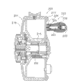
Fig. 3 is the cutaway view Amplified image of handle.
Fig. 4 is the exploded perspective view of described handle.
Fig. 5 is the combination stereogram of described handle.
Fig. 6 is that described handle is along the cutaway view of the A-A line among Fig. 3.
Fig. 7 is the figure that is equivalent to Fig. 5 of other embodiments.
Fig. 8 is the figure that is equivalent to Fig. 5 of other embodiments.
Fig. 9 is the figure that is equivalent to Fig. 5 of other embodiments.
Figure 10 is the figure that is equivalent to Fig. 3 of other embodiments.
Figure 11 is the figure that is equivalent to Fig. 3 of other embodiments.
Figure 12 is the part cutaway top view that has adopted the double-bearing fish-line wheel of other embodiments of the present invention.
Figure 13 is the profile that has adopted the single-shaft fishing line wheel of other embodiments of the present invention.
Description of reference numerals
1: Handleset, 2: reel, 4: spool, 5: rotor, 21: handle arms, 22: handle axle, 23: handle, 31: cylindrical portion, 31a: cylindrical shell, 31b: rotation prevention portion, 31c: internal thread part, 31d: protuberance, 31e: inner core, 32: handle portion, 32a: handle body, 32b: first hand, 32c: second hand, 33: cap member, 33a: external thread part, 33b: head, 33c: fastener, 34: annulus, 34a: non-circular hole, 34b: circular port, 34c: machining section.
Embodiment
As shown in Figures 1 and 2, adopt the spinning reel of an embodiment of the invention to have Handleset 1, Handleset 1 is supported and make Handleset 1 relatively reel 2, rotor 5 and the spool 4 of its rotation.Rotor 5 is supported in the anterior of reel 2 and can rotates with respect to reel 2, and this rotor 5 is used for making fishing line to be wound on the spool 4.Spool 4 is configured in the anterior of rotor 5 and can moves with respect to rotor 5 along fore-and-aft direction, and spool 4 is used for fishing line is wound on its outer peripheral face.In addition, Handleset 1 both can be installed in the right side (with reference to Fig. 1) of reel 2, also can be installed in the left side (with reference to Fig. 2) of reel 2, cap body 19 is housed in that a side of Handleset 1 (right side of the reel 2 among Fig. 2) is not installed.
As shown in Figure 2, Handleset 1 has handle arms 21, handle axle 22 and handle 23, wherein, top and relative handle axial region 7 that handle arms 21 is installed in handle axial region 7 can not rotate, handle axle 22 is fixed on the front end of handle arms 21, handle 23 is installed on the handle axle 22, can be with respect to handle axle 22 rotation but can not be mobile vertically with respect to handle axle 22.
As shown in Figure 2, the bar-like member of handle arms 21 for for example being made by aluminium alloy, and to the side slight curvature towards reel 2.One end of handle arms 21 (downside end of Fig. 2) is connected to the top ends (Fig. 2 left end) of handle axial region 7 by bolt member 20, and make handle arms 21 can approach with reel 2 or away from direction swing.Dispose to be parallel to the handle axle 22 that the mode of handle axial region 7 is fixed thereon at the other end (upper side end of Fig. 2) of handle arms 21.
Such as expression that Fig. 3 amplifies, handle axle 22 disposes in the axis mode parallel with handle axial region 7 (with reference to Fig. 2), this handle axle 22 is by such as metal axles such as stainless steel alloies, be formed with the external thread part 22a less than the diameter of other parts at its cardinal extremity, be formed with the second screwed hole 22b at the opposite side end face.In addition, be formed with the instrument fastener 22c larger than other parts diameter near external thread part 22a place.External thread part 22a can screw with the first screwed hole 21c, screws and handle axle 22 can be fixed on the handle arms 21 by this.Outer peripheral face at instrument fastener 22c is formed with the one group of parallel planar portions 22d that can be used for locking the tool operations such as spanner.Connecing on the part and handle axle 22 top peripheral parts of facing with instrument fastener 22c of handle axle 22 peripheral parts, dispose bearing 30a, 30b.Utilize this bearing 30a, 30b to be supported on handle 23 on the handle axle 22 and make the handle 23 can be with respect to handle axle 22 rotation.By the bolt member 28 that is installed on the second screwed hole 22b bearing 30b is installed on the handle axle 22, this bearing 30b can not be moved vertically with respect to handle axle 22.This bolt member 28 can not come off from handle axle 22 handle 23 by bearing 30b.
To shown in Figure 6, handle 23 has the annulus 34 that handle portion 32, cap member 33 and the aluminium alloy of cylindrical portion 31 that synthetic resin makes, cork are made such as Fig. 3.Wherein, cylindrical portion 31 is installed on the handle axle 22, can be relative to handle axle 22 rotation but can not move vertically relative to handle axle 22; Handle portion 32 is adhesively fixed on the cylindrical portion 31 in the mode of the outer circumferential side of covering cylindrical portion 31; Cap member 33 is used for sealing the opening of the top ends of handle portion 32; Annulus 34 is installed in the base end part of cylindrical portion 31, and its outer surface is to exposing outside and be implemented machining.
To shown in Figure 6, cylindrical portion 31 has cylindrical shell 31a, rotation prevention portion 31b, internal thread part 31c, protuberance 31d and inner core 31e such as Fig. 3.Wherein, cylindrical shell 31a is installed in the outer circumferential side of handle axle 22 and relatively handle axle 22 rotations; Rotation prevention portion 31b is formed at the periphery of end of armrest shaft arm 21 1 sides (left side among Fig. 3) of cylindrical shell 31a, is used for preventing that annulus 34 is with respect to the rotation of cylindrical shell 31a; Cylindrical shell 31a away from the end upper shed of handle arms 21 1 sides (right side among Fig. 3) and form internal thread part 31c; Protuberance 31d protrudes from the peripheral part of cylindrical shell 31a and forms; Inner core 31e insert-molding (insert moulding) is in the interior perimembranous of cylindrical shell 31a.
As shown in Figures 3 and 4, protuberance 31d is formed by axial (longitudinally) along cylindrical shell 31a, and as shown in Figure 6, protuberance 31d circumferentially equidistantly is configured in the protuberance at eight places for the edge.In the present embodiment, by protuberance 31d is set, in the time of in the handle body 32a that cylindrical portion 31 is pressed into the handle portion 32 of mentioning later, by contacting of week in this protuberance 31d peripheral part and the handle body 32a, can prevent that the rotation of the relative cylindrical shell 31a of handle body 32a and handle body 32a from coming off from cylindrical shell 31a.
The cartridge of inner core 31e for forming by the machining to aluminum alloy materials, it is by the interior perimembranous of insert-molding in cylindrical shell 31a.In the present embodiment, adopt inner core 31e, can be in the distortion of seeking to suppress when whole quality alleviates cylindrical shell 31a.
To shown in Figure 6, handle portion 32 has handle body 32a such as Fig. 3, and this handle body 32a is that axial length is greater than the flat thin bar-shaped cartridge of radical length.Handle body 32a is cartridge, the mode that this handle body 32a contacts with rotation prevention portion 31b with base end part (left side among Fig. 3) side from top ends (right side Fig. 3) the side direction cylindrical shell 31a of cylindrical shell 31a is adhered and is fixed in the outer circumferential side of cylindrical shell 31a.Handle body 32a is made by cork, this handle body 32a can by from top ends one side of the top ends one side direction annulus 34 of cylindrical shell 31a by to the peripheral part of cylindrical shell 31a.Scribble bonding agent between the interior perimembranous of handle body 32a and the peripheral part of cylindrical shell 31a.Can be fixed on handle portion 32 on the cylindrical shell 31a and be the shape that shrink at axial middle part, the side face in opposite directions of its contraction flow region both sides is crooked and form the grip end face to the inside smoothly in the axial direction.What the grip end face was formed when grasping and finger tip is fitted is approximate rectangular.Handle body 32a forms at the different elongated shape of different axial location radial thickness, and in addition, handle body 32a is the shape with respect to handle axle 22 symmetries.Be equipped with to seal the cap member 33 of this opening at the opening of the top ends (right side among Fig. 3) of handle body 32a.
To shown in Figure 5, cap member 33 has external thread part 33a, head 33b and fastener 33c such as Fig. 3.Wherein, external thread part 33a can screw with the internal thread part 31c that is formed at the interior perimembranous of cylindrical portion 31 top ends (right side among Fig. 3).The diameter of head 33b is greater than the external diameter of external thread part 33a, and this head 33b can contact with the top ends (right side among Fig. 3) of handle body 32a, with the opening at sealing external thread part 33a place.Fastener 33c is formed on the head 33b, for locking tool operation.After utilizing bolt member 28 to be installed to handle 23 on the handle axle 22, again cap member 33 is fixed on the top ends (right side among Fig. 3) of handle body 32a.
To shown in Figure 5, the mode that annulus 34 exposes with its outer surface is installed in the base end part of cylindrical shell 31a such as Fig. 3, the endless member that this annulus 34 is made for the aluminium alloy that implements on its outer surface machining.Inner peripheral surface at annulus 34 is formed with towards the slightly large non-circular hole 34a in the aperture of base end part side opening, and towards the aperture of top ends side opening slightly little circular port 34b.The interior shape of non-circular hole 34a is non-circular octagon, with can be identical with the profile of rotation prevention portion 31b, so that after being installed to annulus 34 on the cylindrical portion 31, this non-circular hole 34a can engage with rotation prevention portion 31b.In the present embodiment, the non-circular rotation prevention portion 31b by making cylindrical portion 31 is with on the non-circular hole 34a of annulus 34 engages, and can utilize simple structure just two parts to be fixed as can not counterrotating state.
To shown in Figure 5, the 34c of machining section that just formed by machining is arranged on the outer surface of annulus 34 such as Fig. 3 before assembling cylindrical portion 31 and handle portion 32.The 34c of machining section has profile for the slot part of recessed formation radially (installation direction along annulus 34 extends), makes the 34c of machining section become concavo-convex.In the present embodiment, on the annulus 34 of the aluminium alloy that is separately made with cylindrical portion 31 and handle portion 32, be subjected to easily the machining that forms groove.In addition, 34c arranges jog in machining section, can prevent that cylindrical portion 31 is rotated with this cap member 33 when screwing above-mentioned cap member 33.
By machining after the surface of annulus 34 forms the machining 34c of section, can impose the surface of annulus 34 as the pellumina of anodized and process, make it to form the alumina layer as anode oxide film.In the present embodiment, by processing the alumina layer that generates to forming by pellumina on the annulus 34, can in the anticorrosive property that strengthens annulus 34, keep the high strength of annulus 34.
As shown in Figure 2, Handleset 1 also has handle axial region 7, and this handle axial region 7 is installed on the interior perimembranous of main gear shaft 10 in the mode of relatively main gear shaft 10 rotations, and is configured to more outstanding to the axial outside than the top ends of main gear shaft 10.As shown in Figure 2, the profile of handle axial region 7 is that rectangle etc. is non-circular, is installed in the through hole of main gear shaft 10, can not rotate relative to main gear shaft 10 but can move relative to main gear shaft 10 vertically.Interior all sides in the end of handle axial region 7 (right-hand end among Fig. 2) are formed with internal thread part, screw by the external thread part that makes bolt member on the internal thread part of the handle axial region 7 of installing in the through hole, can prevent that handle axial region 7 from coming off from main gear shaft 10.In addition, can pass through in the outer end of handle axial region 7 (left end among Fig. 2) bolt member 20 fixed handle arms 21.
As shown in Figures 1 and 2, reel 2 has reel 2a, cover 2b, pole mount pad 2c and cap assembly 2d (with reference to Fig. 1).Wherein, reel 2a has opening; Cover 2b can be installed in reel 2a upward and can pull down from this reel 2a, in order to seal opening; Pole mount pad 2c begins to extend to the front upper place sideling from cover 2b; Cap assembly 2d is installed as from the rear portion of reel 2a and cover 2b and begins to cross the bottom.Inside at reel 2a has cavity.
As shown in Figure 1, rotor 5 has cylindrical portion 30 and the toward each other the first rotor arm 51, the second rotor arm 52 that are arranged on cylindrical portion 30 sides.Cylindrical portion 30 and the first rotor arm 51 and the second rotor arm 52 are integrally formed.
As shown in Figure 1, the first rotor arm 51 forward with outstanding state bending toward the outer side from cylindrical portion 30 beginnings and is extended.At the top of the first rotor arm 51 outer circumferential side first of relatively its swing is installed and leads arm support unit 40.The line roller 41 of spool 4 is installed fishing line is guided on the first top of leading arm support unit 40.The second rotor arm 52 forwards extension to foreign side with outstanding state bending from cylindrical portion 30.Second of relatively its swing is installed on the top outer circumferential side of the 2nd rotor arm 52 leads arm support unit 42.Line roller 41 and second is led to be fixed with between the arm support unit 42 and is led arm 43 with roughly taking the shape of the letter U of becoming of bending wire.Above-mentioned first leads arm support unit 40, second leads arm support unit 42, line roller 41 and leads arm 43 and consist of fishing lines and lead arm 44.Fishing line is led arm 44 and can be swung between lead location and the unwrapping wire that is turned into from lead location position.
As shown in Figure 1, spool 4 is configured between the first rotor arm 51 and the second rotor arm 52 of rotor 5, is installed in the top of spool axle 15 by unloading force mechanisms 60.
Next, operation and the action of fishing line reel are described.
In when fishing, emit fishing line in order to jettisoning from reel 2, make fishing line lead arm 44 reverse rotations, in case like this, first lead arm support unit 40 and second and lead arm support unit 42 and will swing so, make fishing line lead arm 44 and switch to the unwrapping wire position.Under this state, can use the forefinger of the hand of holding fishing rod to hook fishing line on one side, Yi Bian jettisoning.So fishing line is effectively forwards emitted under the action of gravitation of fishhook assembly.After this, if make Handleset 1 along the take-up direction rotation, to utilize so not shown rotor driving mechanism to make rotor 5 along the take-up direction rotation, fishing line is led arm 44 and return to the take-up position under the not shown effect of leading the arm switching mechanism, and fishing line will be winding on the spool 4.
The handle 23 of this kind spinning reel has the annulus 34 that cylindrical portion 31 that synthetic resin makes and aluminium alloy are made, and wherein, annulus 34 is independent of cylindrical portion 31 and handle portion 32 arranges, and its outer surface is subjected to machining.In the present embodiment, owing between handle arms 21 and handle portion 32, be provided with the annulus 34 that aluminium alloy is made, even so rock because making for a long time to produce between them, the annulus 34 that aluminium alloy is made contacts with handle arms 21, rather than the base end part of handle portion 32 is contacted with handle arms 21.Therefore, even in the situation that handle portion 32 is made by cork, the base end part of handle portion 32 can not contact with handle arms 21 yet, and this is just so that can when keeping handle 23 smooth and easy rotations, also can suppress by the annulus 34 of aluminium alloy system the wearing and tearing of handle 23.Therefore, can in the smooth and easy rotation of keeping handle 23, suppress the wearing and tearing of handle 23.
Other embodiment
(a) although the explanation of carrying out as an example of spinning reel example in the above-described embodiment, the present invention is applicable to the handle of the fishing line reel of double-bearing fish-line wheel shown in Figure 12 and as shown in figure 13 other types such as single-shaft fishing line wheel too.In addition, handle grip end of the present invention is not limited to double-handle, is applicable to too single handle.
As shown in figure 12, adopt the double-bearing fish-line wheel of other embodiments of the present invention to use the platypelloid type fishing line reel for jettisoninging.This double-bearing fish-line wheel has reel 101, be used for the spool 112 make the Handleset 102 of spool rotation and to be used for spiral, wherein, Handleset 102 is configured in the side of reel 101, spool 112 is installed on the inside of reel 101, and this spool 112 can and can unload from reel 101 with respect to reel 101 rotations.Being equipped with for the star-like force mechanisms 103 that unloads of adjusting brake force by reel 101 1 sides of Handleset 102.
The internal configurations of reel 101 has spool 112, not shown smooth winding mechanism and not shown rotary transfer machine.Wherein, spool 112 disposes axially to intersect at the axial mode of fishing rod, and smooth winding mechanism is used for making fishing line to be wound on equably on the spool 112, and rotary transfer machine is used for the rotation of Handleset 102 is delivered to spool 112.Comprise Handle axis 120, not shown clutch mechanism and the not shown force mechanisms that unloads at rotary transfer machine.Wherein, Handleset 102 is installed on the top of Handle axis 120, and clutch mechanism is used for 112 rotations of transmitting are delivered in permission (on) and forbid switching (off) from Handleset 102 to spool.Handle axis 120 is subjected to reel 101 supportings and can rotates with respect to reel 101.At the rear portion of framework 105 the relatively clutch control lever 117 of framework 105 swings is installed, it is used as the thumb push rod and comes clutch mechanism is engaged and lock out operation.
Handle 123 for such double-bearing fish-line wheel, because the same with above-mentioned embodiment, have the cylindrical portion 131 of being made by synthetic resin and the annulus 134 of being made by aluminium alloy, this annulus 134 and cylindrical portion 131 and handle portion 132 split settings and implement machining at outer surface, so, can in the Smooth Rotation of keeping handle 123, suppress the wearing and tearing of handle 123.
As shown in figure 13, adopt other the single-shaft fishing line wheel of embodiment of the present invention to have reel 201, spool axle 202 and spool 203.Wherein, spool axle 202 is by reel 201 cantilever support; Spool 203 is disposed on the spool axle 202 in the mode of relatively spool axle 202 rotations, fishing line can be wound on the outer peripheral face of this spool 203.Spool 203 has the spiral main part 215 of tubular, discoideus convex edge 216 and evagination edge 217.Wherein, convex edge 216 is integrally formed on the end of spiral main part 215 with spiral main part 215, and evagination edge 217 is installed in the other end of spiral main part 215, in order to cover the opening portion of reel 201.The position near periphery is equipped with handle 223 on the outer surface of flange part 217 outside.Handle 223 has the annulus 234 that cylindrical portion 231 that synthetic resin makes, handle portion 232, cap member 233 and aluminium alloy that cork is made are made.Wherein, cylindrical portion 231 is installed on the handle axle 222, can be with respect to handle axle 222 rotation but can not move vertically relative to handle axle 222; Handle portion 232 is adhesively fixed in the mode of the outer circumferential side of covering cylindrical portion 231; Cap member 233 is used for sealing the opening of the top ends of handle portion 232; Annulus 234 is installed in the base end part of cylindrical portion 231, and the outer surface of this annulus 234 is to exposing outside and be implemented machining.In addition, because identical after Reference numeral interpolation 200 of the structure of the structure of handle 223 and above-mentioned embodiment, so omit its specific description.
For the handle 223 of this kind single-shaft fishing line wheel, because the same with above-mentioned embodiment, has the annulus 234 that the cylindrical portion 231 made by synthetic resin and aluminium alloy are made, this annulus 234 and cylindrical portion 231 and handle portion 232 split settings and implement machining at outer peripheral face, so, can when keeping handle 223 smooth and easy rotations, suppress the wearing and tearing of handle 223.
(b) in the above-described embodiment, for cylindrical portion 31, on metal inner core 31e, but the structure that metal inner core is not set also is fine the cylindrical shell 31a that is made by hard resin by insert-molding.In addition, the material of cylindrical portion 31 is not limited to above-mentioned material, also can utilize EVA resin synthetic resin in addition to make.
(c) in the above-described embodiment, the 34c of machining section is the slot part of radially recessed formation, but is not limited to this.The 34c of machining section can be for example for as shown in Figure 7 profile is the slot part that circumferentially extend on the edge of recessed formation, also can utilize as shown in Figure 8 the slot part of the sawtooth decorative pattern that annular knurl is processed to form.
(d) in the above-described embodiment, handle portion 32 is formed by parts, also can be as shown in Figure 9, consisted of by the first hand 32b that is configured in the base end part side and the second hand 32c that is configured in top ends, and adopt at second hand 32c and to be different from the material of first hand 32b and to make it color and be different from first hand 32b.And, also can be implemented in the processing that lateral surface is covered with paint, lacquer, colour wash, etc. iridescent to second hand 32c as illustrated in fig. 9.
(e) in the above-described embodiment, handle portion 32 is made by cork, but the material of handle portion 32 is not limited to this, can be as shown in figure 10, the elastomer resins such as synthetic resin such as elastomer or neoprene of employing and polyurethane rubber or flexible vinyl chloride (PVC) are made, also can by as shown in figure 11, adopt aluminium alloy to make.
Claims (14)
1. the handle of a fishing line reel, it is installed on the handle axle and can rotates with respect to this handle axle, wherein, described handle axle is fixed on the top of the handle arms of fishing line reel, it is characterized in that, described handle has: cylindrical portion, it is made by synthetic resin, be installed in described handle axle outer circumferential side and can be with respect to the rotation of this handle axle;
Annulus, it is made of metal, and is installed in the base end part of described cylindrical portion, and its outer surface is to exposing outside and be implemented machining;
Handle portion, its top ends one side of described annulus from top ends one side direction of described cylindrical portion is installed on the peripheral part of described cylindrical portion,
Described annulus with can not be relatively described the mode of cylindrical portion rotation be fixed in the base end part of described cylindrical portion.
2. the handle of fishing line reel as claimed in claim 1 is characterized in that, described cylindrical portion has rotation prevention portion, and this rotation prevention portion is formed at the base end part of cylindrical portion, and is larger than the external diameter of the other parts of described cylindrical portion, and its profile is non-circular,
Described annulus has the section of being stuck, and this interior shape that is stuck section is non-circular for what can engage with described rotation prevention portion.
3. the handle of fishing line reel as claimed in claim 1 or 2 is characterized in that, the outer peripheral face of described annulus forms concavo-convex.
4. the handle of fishing line reel as claimed in claim 1 or 2 is characterized in that, the outer surface of described annulus has been implemented annular knurl processing.
5. the handle of fishing line reel as claimed in claim 1 or 2 is characterized in that, described annulus is bonded to the base end part of described cylindrical portion.
6. the handle of fishing line reel as claimed in claim 1 or 2 is characterized in that, described handle portion is pressed to the peripheral part of described cylindrical portion.
7. the handle of fishing line reel as claimed in claim 1 or 2 is characterized in that, described handle portion is by any the making in synthetic resin, the cork.
8. the handle of fishing line reel as claimed in claim 1 or 2, it is characterized in that, described handle portion has first hand and second hand, wherein, described first hand is configured in the base end part side, described second hand is configured in the top ends side, and this second hand material is different from the material with described first hand.
9. the handle of fishing line reel as claimed in claim 8 is characterized in that, the outer surface of described second hand has been carried out covering with paint, lacquer, colour wash, etc. the processing of iridescent.
10. the handle of fishing line reel as claimed in claim 1 or 2 is characterized in that, described annulus is made by aluminium alloy.
11. the handle of fishing line reel as claimed in claim 1 or 2 is characterized in that, the surface of described annulus is formed with anode oxide film through anodized.
12. the handle of fishing line reel as claimed in claim 1 or 2 is characterized in that, described fishing line reel is spinning reel.
13. the handle of fishing line reel as claimed in claim 1 or 2 is characterized in that, described fishing line reel is double-bearing fish-line wheel.
14. the handle of fishing line reel as claimed in claim 1 or 2 is characterized in that, described fishing line reel is single-shaft fishing line wheel.
Applications Claiming Priority (3)
| Application Number | Priority Date | Filing Date | Title |
|---|---|---|---|
| JP2008117611 | 2008-04-28 | ||
| JP2008117611A JP5205120B2 (en) | 2008-04-28 | 2008-04-28 | Handle handle for fishing reel |
| JP2008-117611 | 2008-04-28 |
Publications (2)
| Publication Number | Publication Date |
|---|---|
| CN101569298A CN101569298A (en) | 2009-11-04 |
| CN101569298B true CN101569298B (en) | 2013-03-13 |
Family
ID=41228894
Family Applications (1)
| Application Number | Title | Priority Date | Filing Date |
|---|---|---|---|
| CN2009101326943A Active CN101569298B (en) | 2008-04-28 | 2009-04-07 | Handle for fishing wheel |
Country Status (4)
| Country | Link |
|---|---|
| JP (1) | JP5205120B2 (en) |
| KR (1) | KR101488151B1 (en) |
| CN (1) | CN101569298B (en) |
| TW (1) | TWI479992B (en) |
Families Citing this family (10)
| Publication number | Priority date | Publication date | Assignee | Title |
|---|---|---|---|---|
| JP3164243U (en) * | 2010-09-08 | 2010-11-18 | 広明 舟岡 | Fishing reel assembly handle |
| KR101282412B1 (en) * | 2012-01-03 | 2013-07-04 | 주식회사 도요엔지니어링 | Knob assembly for fishing reel |
| US9332744B2 (en) * | 2012-05-29 | 2016-05-10 | Globeride, Inc. | Fishing spinning reel |
| JP2015047109A (en) * | 2013-08-30 | 2015-03-16 | グローブライド株式会社 | Knob of fishing reel |
| JP2015047108A (en) | 2013-08-30 | 2015-03-16 | グローブライド株式会社 | Knob of fishing reel and assembling method |
| JP6956602B2 (en) * | 2017-11-13 | 2021-11-02 | 株式会社シマノ | Handle knob of fishing reel and reel for fishing |
| CN108515995A (en) * | 2018-04-27 | 2018-09-11 | 天津市友森金属结构有限公司 | A kind of convenient and practical heat preservation table trolley |
| KR102118292B1 (en) | 2019-12-03 | 2020-06-02 | 주식회사 샤크컴퍼니 | Apparetus to fix handle for preventing release of fishing reel |
| KR200495872Y1 (en) | 2020-03-17 | 2022-09-06 | 주식회사 바낙스 | Center shaft variable power handle for bait reel |
| KR20230100351A (en) | 2021-12-28 | 2023-07-05 | 주식회사 바낙스 | Lightweight structure of handle knob of fishing reel |
Citations (2)
| Publication number | Priority date | Publication date | Assignee | Title |
|---|---|---|---|---|
| CN101243784A (en) * | 2007-02-13 | 2008-08-20 | 株式会社岛野马来西亚配件厂有限公司 | Spinning reel handle assembly |
| CN1757284B (en) * | 2004-10-06 | 2010-12-22 | 株式会社岛野 | Handle knob and handle assembly for a fishing reel |
Family Cites Families (7)
| Publication number | Priority date | Publication date | Assignee | Title |
|---|---|---|---|---|
| JPS5745804Y2 (en) * | 1979-12-06 | 1982-10-08 | ||
| JP3593407B2 (en) * | 1996-01-24 | 2004-11-24 | 株式会社シマノ | Reel handle |
| JP3977730B2 (en) * | 2002-12-03 | 2007-09-19 | 株式会社シマノ | Fishing reel parts |
| JP2004236541A (en) * | 2003-02-04 | 2004-08-26 | Daiwa Seiko Inc | Handle of reel for fishing |
| JP2006238746A (en) * | 2005-03-01 | 2006-09-14 | Shimano Inc | Handle grip of fishing reel |
| JP4704801B2 (en) * | 2005-04-28 | 2011-06-22 | 株式会社シマノ | Handle handle for fishing reel |
| JP5010860B2 (en) * | 2006-06-30 | 2012-08-29 | 株式会社シマノ | Handle handle for fishing reel |
-
2008
- 2008-04-28 JP JP2008117611A patent/JP5205120B2/en active Active
-
2009
- 2009-03-03 KR KR20090017836A patent/KR101488151B1/en active IP Right Grant
- 2009-03-31 TW TW098110736A patent/TWI479992B/en active
- 2009-04-07 CN CN2009101326943A patent/CN101569298B/en active Active
Patent Citations (2)
| Publication number | Priority date | Publication date | Assignee | Title |
|---|---|---|---|---|
| CN1757284B (en) * | 2004-10-06 | 2010-12-22 | 株式会社岛野 | Handle knob and handle assembly for a fishing reel |
| CN101243784A (en) * | 2007-02-13 | 2008-08-20 | 株式会社岛野马来西亚配件厂有限公司 | Spinning reel handle assembly |
Non-Patent Citations (2)
| Title |
|---|
| JP特开2003-112AA 2003.01.07 |
| JP特开2008-5793A 2008.01.17 |
Also Published As
| Publication number | Publication date |
|---|---|
| TW201012390A (en) | 2010-04-01 |
| TWI479992B (en) | 2015-04-11 |
| CN101569298A (en) | 2009-11-04 |
| KR20090113756A (en) | 2009-11-02 |
| KR101488151B1 (en) | 2015-01-30 |
| JP2009261367A (en) | 2009-11-12 |
| JP5205120B2 (en) | 2013-06-05 |
Similar Documents
| Publication | Publication Date | Title |
|---|---|---|
| CN101569298B (en) | Handle for fishing wheel | |
| JP2009261367A5 (en) | ||
| KR20060045676A (en) | Reel unit for dual-bearing reel | |
| EP2792238B1 (en) | Line roller and fishing line guide mechanism using same | |
| US10010061B2 (en) | Spinning reel | |
| KR101292699B1 (en) | Dual bearing reel | |
| EP1500330B1 (en) | Dual-bearing reel | |
| CN101461352A (en) | Fishing line guiding mechanism of spinning reel | |
| TW200302696A (en) | Reel unit for spinning reel | |
| KR101000347B1 (en) | Reel unit for spinning reel | |
| US7926756B2 (en) | Spinning reel drag knob | |
| US20040140385A1 (en) | Handle assembly for a spinning reel | |
| US20020117570A1 (en) | Spinning reel spool | |
| US20040104291A1 (en) | Fishing reel component | |
| JP2002218871A (en) | Structure for fastening component for fishing tackle | |
| KR101058363B1 (en) | Master Gear of Spinning Reel | |
| US10588303B2 (en) | Dual-bearing reel | |
| JP5010860B2 (en) | Handle handle for fishing reel | |
| CN101461353B (en) | Brake operation button component of spinning reel | |
| JP2019110761A (en) | Spool of fishing reel and fishing reel | |
| JP4141275B2 (en) | Spinning reel body | |
| JP2004229544A (en) | Reel main body for spinning reel | |
| JP5185177B2 (en) | Spindle reel handle mounting structure | |
| EP2898771B1 (en) | Fishing reel | |
| JP2000093054A (en) | Reel for fishing |
Legal Events
| Date | Code | Title | Description |
|---|---|---|---|
| C06 | Publication | ||
| PB01 | Publication | ||
| C10 | Entry into substantive examination | ||
| SE01 | Entry into force of request for substantive examination | ||
| C14 | Grant of patent or utility model | ||
| GR01 | Patent grant |