JP5205120B2 - Handle handle for fishing reel - Google Patents
Handle handle for fishing reel Download PDFInfo
- Publication number
- JP5205120B2 JP5205120B2 JP2008117611A JP2008117611A JP5205120B2 JP 5205120 B2 JP5205120 B2 JP 5205120B2 JP 2008117611 A JP2008117611 A JP 2008117611A JP 2008117611 A JP2008117611 A JP 2008117611A JP 5205120 B2 JP5205120 B2 JP 5205120B2
- Authority
- JP
- Japan
- Prior art keywords
- handle
- fishing reel
- annular
- reel according
- cylindrical
- Prior art date
- Legal status (The legal status is an assumption and is not a legal conclusion. Google has not performed a legal analysis and makes no representation as to the accuracy of the status listed.)
- Active
Links
- 230000002093 peripheral effect Effects 0.000 claims description 31
- 229910000838 Al alloy Inorganic materials 0.000 claims description 20
- 229920003002 synthetic resin Polymers 0.000 claims description 20
- 239000000057 synthetic resin Substances 0.000 claims description 20
- 239000007799 cork Substances 0.000 claims description 14
- 229910052751 metal Inorganic materials 0.000 claims description 14
- 239000002184 metal Substances 0.000 claims description 14
- 238000009987 spinning Methods 0.000 claims description 9
- 230000009977 dual effect Effects 0.000 claims description 7
- 239000000463 material Substances 0.000 claims description 6
- 238000000576 coating method Methods 0.000 claims description 5
- 238000002048 anodisation reaction Methods 0.000 claims 1
- 238000005520 cutting process Methods 0.000 description 13
- 229920005989 resin Polymers 0.000 description 7
- 239000011347 resin Substances 0.000 description 7
- 229920001971 elastomer Polymers 0.000 description 5
- 239000000806 elastomer Substances 0.000 description 5
- 238000007743 anodising Methods 0.000 description 4
- 238000000034 method Methods 0.000 description 4
- 238000004804 winding Methods 0.000 description 4
- 230000005540 biological transmission Effects 0.000 description 2
- 238000005260 corrosion Methods 0.000 description 2
- 230000007797 corrosion Effects 0.000 description 2
- 230000007774 longterm Effects 0.000 description 2
- 238000000465 moulding Methods 0.000 description 2
- 241000276420 Lophius piscatorius Species 0.000 description 1
- 229920006311 Urethane elastomer Polymers 0.000 description 1
- BZHJMEDXRYGGRV-UHFFFAOYSA-N Vinyl chloride Chemical compound ClC=C BZHJMEDXRYGGRV-UHFFFAOYSA-N 0.000 description 1
- 239000000853 adhesive Substances 0.000 description 1
- 230000001070 adhesive effect Effects 0.000 description 1
- 229910045601 alloy Inorganic materials 0.000 description 1
- 239000000956 alloy Substances 0.000 description 1
- 239000010407 anodic oxide Substances 0.000 description 1
- 238000005266 casting Methods 0.000 description 1
- 239000011248 coating agent Substances 0.000 description 1
- 239000003086 colorant Substances 0.000 description 1
- 125000004122 cyclic group Chemical group 0.000 description 1
- 210000003811 finger Anatomy 0.000 description 1
- 239000005445 natural material Substances 0.000 description 1
- 239000003973 paint Substances 0.000 description 1
- 229920001084 poly(chloroprene) Polymers 0.000 description 1
- 210000003813 thumb Anatomy 0.000 description 1
Images


Classifications
-
- A—HUMAN NECESSITIES
- A01—AGRICULTURE; FORESTRY; ANIMAL HUSBANDRY; HUNTING; TRAPPING; FISHING
- A01K—ANIMAL HUSBANDRY; CARE OF BIRDS, FISHES, INSECTS; FISHING; REARING OR BREEDING ANIMALS, NOT OTHERWISE PROVIDED FOR; NEW BREEDS OF ANIMALS
- A01K89/00—Reels
- A01K89/006—Hand crank features
Description
本発明は、ハンドル把手、特に、釣り用リールのハンドルアームの先端に固定された把手軸に回転自在に装着されるハンドル把手に関する。 The present invention relates to a handle handle, and more particularly to a handle handle that is rotatably attached to a handle shaft fixed to the tip of a handle arm of a fishing reel.
スピニングリールや、両軸受リール等の釣り用リールのハンドル軸の先端には、ハンドル組立体が固定されている。ハンドル組立体は、ハンドル軸の先端に回転不能に装着されたハンドルアームと、ハンドルアームの先端に回転不能に固定された把手軸と、把手軸に回転自在に装着されたハンドル把手とを有している。 A handle assembly is fixed to the tip of a handle shaft of a fishing reel such as a spinning reel or a dual-bearing reel. The handle assembly includes a handle arm that is non-rotatably attached to the tip of the handle shaft, a handle shaft that is non-rotatably fixed to the tip of the handle arm, and a handle handle that is rotatably attached to the handle shaft. ing.
このようなハンドル把手は、把手軸に回転自在に支持された筒状部と、筒状部の外周を覆うように設けられた鼓状の把手部とを有している。筒状部は、把手軸に対して回転自在かつ軸方向移動不能に装着されており、把手軸の先端部にねじ止めされている。 Such a handle handle has a cylindrical portion that is rotatably supported by the handle shaft, and a drum-shaped handle portion that is provided so as to cover the outer periphery of the cylindrical portion. The cylindrical portion is mounted so as to be rotatable and non-movable in the axial direction with respect to the handle shaft, and is screwed to the distal end portion of the handle shaft.
このようなハンドル把手では、把手部は、たとえばエラストマー等の合成樹脂やコルク等を加工して筒状部の外周部全体にわたって接着固定したものが知られている(たとえば、特許文献1参照)。
前記従来の釣り用リールのハンドル把手は、合成樹脂やコルク等により形成された把手部が筒状部の外周部全体にわたって接着固定されているので、把手部全体が外観に露出する構成になっている。 The handle handle of the conventional fishing reel has a configuration in which the handle portion formed of synthetic resin, cork, or the like is bonded and fixed over the entire outer peripheral portion of the cylindrical portion, so that the entire handle portion is exposed to the outside. Yes.
しかし、把手部全体が外観に露出している従来の構成では、特に、把手部の基端部は、ハンドルアームに近接して配置されているので、長年の使用によってがたつきが生じると、把手部の基端部がハンドルアームに接触してしまうことがある。このように把手部の基端部がハンドルアームに接触すると、把手部がエラストマー等の軟質樹脂により形成されている場合には、把手部とハンドルアームとの接触摩擦によってハンドル把手の滑らかな回転を阻害したり、あるいは、把手部がコルク等の天然素材により形成されている場合には、比較的強度が弱いために、把手部自身が磨耗し破断したりするおそれがある。 However, in the conventional configuration in which the entire handle portion is exposed to the outside, particularly, the base end portion of the handle portion is disposed close to the handle arm, so that when rattling occurs due to long-term use, The proximal end of the handle may come into contact with the handle arm. In this way, when the proximal end portion of the handle portion comes into contact with the handle arm, when the handle portion is formed of a soft resin such as elastomer, the handle handle is smoothly rotated by contact friction between the handle portion and the handle arm. If the handle is made of a natural material such as cork, the handle may be worn and broken due to its relatively low strength.
本発明の課題は、釣り用リールのハンドル把手において、ハンドル把手の滑らかな回転を維持しながら、ハンドル把手の磨耗を抑えることにある。 An object of the present invention is to suppress wear of a handle handle while maintaining a smooth rotation of the handle handle in a handle handle of a fishing reel.
発明1に係る釣り用リールのハンドル把手は、釣り用リールのハンドルアームの先端に固定された把手軸に回転自在に装着されるハンドル把手であって、把手軸の外周側に回転自在に装着された合成樹脂製の筒状部と、筒状部の基端部に外側面が露出するように装着され外側面に切削加工が施された金属製の環状部と、筒状部の先端部から環状部の先端部に向けて筒状部の外周部に装着された把手部とを備えている。筒状部は、基端部に他の部分の外径より大径となるようにかつ外形が非円形となるように形成された係合部を、有している。環状部は、内形が非円形となるように形成され、係合部が係合可能な被係合部を有している。係合部及び被係合部の係合によって、環状部は、筒状部の基端部に相対回転不能に固定され、且つ筒状部の係合部と把手部とによって挟持される。 The handle handle of the fishing reel according to the first aspect of the present invention is a handle handle that is rotatably attached to a handle shaft fixed to the tip of the handle arm of the fishing reel, and is rotatably attached to the outer peripheral side of the handle shaft. A cylindrical portion made of synthetic resin, a metal annular portion that is mounted so that the outer surface is exposed at the base end portion of the cylindrical portion, and the outer surface is cut, and a distal end portion of the cylindrical portion And a grip portion attached to the outer peripheral portion of the cylindrical portion toward the tip portion of the annular portion. The cylindrical portion has an engagement portion formed at the base end portion so as to have a larger diameter than the outer diameter of other portions and to have a non-circular outer shape. The annular portion is formed so that the inner shape is non-circular, and has an engaged portion to which the engaging portion can be engaged. By the engagement of the engaging portion and the engaged portion, the annular portion is fixed to the base end portion of the cylindrical portion so as not to be relatively rotatable, and is sandwiched between the engaging portion and the handle portion of the cylindrical portion.
このハンドル把手では、合成樹脂製の筒状部と、筒状部や把手部と別体で設けられ外側面に切削加工が施された金属製の環状部とを主に備えている。ここでは、ハンドルアームと把手部との間に金属製の環状部が設けられているので、長年の使用によってがたつきが生じたとしても、金属製の環状部がハンドルアームに接触するだけで把手部の基端部がハンドルアームに接触することがなくなる。したがって、把手部がたとえばエラストマー等の合成樹脂やコルク等により形成されている場合でも、把手部の基端部がハンドルアームに接触しないことによって、ハンドル把手の滑らかな回転を維持しながら、金属製の環状部によって、ハンドル把手の磨耗を抑えることができる。 This handle handle mainly includes a cylindrical portion made of synthetic resin and a metal annular portion which is provided separately from the cylindrical portion and the handle portion and whose outer surface is cut. Here, since the metal annular part is provided between the handle arm and the handle part, even if the rattling occurs after many years of use, the metal annular part only comes into contact with the handle arm. The proximal end portion of the handle portion does not come into contact with the handle arm. Therefore, even when the handle portion is formed of, for example, a synthetic resin such as elastomer or cork, the base end portion of the handle portion does not contact the handle arm. Wearing of the handle handle can be suppressed by the annular portion.
さらに、ここでは、環状部は筒状部や把手部と別体で設けられているので、たとえば把手部の外形が鼓状である場合でも、筒状部や把手部と別体のたとえばアルミニウム合金等の金属製の環状部を切削加工することが容易になるとともに、切削加工が施された金属製の環状部を外観に露出させることによって、意匠性を向上できる。さらに、ここでは、筒状部は、たとえばEVA樹脂等の合成樹脂製である場合には、把手部及び筒状部全体をアルミニウム合金等の金属により形成する場合に比して、把手部の材質に関わらず、ハンドル全体を軽量化できる。 Furthermore, since the annular portion is provided separately from the cylindrical portion and the handle portion, for example, even when the outer shape of the handle portion is a drum shape, for example, an aluminum alloy separate from the cylindrical portion or the handle portion. It becomes easy to cut an annular portion made of metal such as, and the design property can be improved by exposing the annular portion made of metal to which the cutting has been performed. Further, here, when the cylindrical portion is made of a synthetic resin such as EVA resin, the material of the handle portion is compared with the case where the handle portion and the entire cylindrical portion are formed of a metal such as an aluminum alloy. Regardless, the entire handle can be reduced in weight.
また、この場合、環状部が筒状部に固定されるので、釣人が誤って環状部を掴んだ場合でも、ハンドル把手を操作することができる。さらに、この場合、筒状部の非円形の係合部を、環状部の被係合部に係合させることにより、簡素な構成で両部材を相対回転不能に固定することができる。In this case, since the annular portion is fixed to the cylindrical portion, the handle handle can be operated even when the angler accidentally grasps the annular portion. Furthermore, in this case, by engaging the non-circular engaging portion of the cylindrical portion with the engaged portion of the annular portion, both members can be fixed in a relatively non-rotatable manner with a simple configuration.
発明2に係るハンドル把手は、発明1のハンドル把手において、環状部は、外形が周方向に沿うように凹んで形成された溝部を有している。この場合、環状部は把手部と別体で設けられているので、切削加工によって溝部の形成が容易になる。 A handle handle according to a second aspect of the present invention is the handle handle according to the first aspect of the present invention, wherein the annular portion has a groove portion that is recessed so that the outer shape is along the circumferential direction. In this case, since the annular portion is provided separately from the handle portion, the groove portion can be easily formed by cutting.
発明3に係るハンドル把手は、発明1又は2のハンドル把手において、環状部は、外側面にローレット加工が施されている。この場合、環状部は把手部と別体で設けられているので、切削加工であるローレット加工が容易になるとともに、ぎざぎざ模様の溝部となるローレット加工によって意匠性を向上できる。 The handle handle according to a third aspect is the handle handle according to the first or second aspect, wherein the annular portion is knurled on the outer surface. In this case, since the annular part is provided separately from the handle part, the knurling process, which is a cutting process, is facilitated, and the design can be improved by the knurling process that forms a grooved pattern.
発明4に係るハンドル把手は、発明1から3のいずれかのハンドル把手において、環状部は、筒状部の基端部に接着されている。この場合、たとえば両部材を非円形係合させた状態で接着することにより、環状部と筒状部との固定が強固になる。 A handle handle according to a fourth aspect of the present invention is the handle handle according to any one of the first to third aspects, wherein the annular portion is bonded to the proximal end portion of the cylindrical portion. In this case, for example, by bonding the two members in a non-circular engagement, the annular portion and the cylindrical portion are firmly fixed.
発明5に係るハンドル把手は、発明1から4のいずれかのハンドル把手において、把手部は、筒状部の外周部に圧入されている。この場合、たとえばエラストマー等の合成樹脂やコルク等の把手部を圧入することにより、把手部の取り付けが容易になる。 A handle handle according to a fifth aspect is the handle handle according to any one of the first to fourth aspects, wherein the handle portion is press-fitted into the outer peripheral portion of the cylindrical portion. In this case, for example, by fitting a handle such as a synthetic resin such as elastomer or a cork, the handle can be easily attached.
発明6に係るハンドル把手は、発明1から5のいずれかのハンドル把手において、把手部は、合成樹脂、コルクのいずれかにより形成されている。この場合、把手部を比較的軽量な合成樹脂、コルクのいずれかにより形成することにより、把手部及び筒状部全体を金属製にする場合に比して、ハンドル全体を軽量化できる。 A handle handle according to a sixth aspect of the present invention is the handle handle according to any one of the first to fifth aspects, wherein the handle portion is formed of either synthetic resin or cork. In this case, the handle portion can be made lighter than the case where the handle portion and the entire cylindrical portion are made of metal by forming the handle portion with either a relatively lightweight synthetic resin or cork.
発明7に係るハンドル把手は、発明1から6のいずれかのハンドル把手において、把手部は、基端部側に配置された第1把手部と、先端部側に配置された第1把手部と異なる材質によって形成された第2把手部とを有している。この場合、たとえば第1把手部と第2把手部とで外観が異なる色となるようにすることで、意匠性を向上できる。 A handle handle according to a seventh aspect of the present invention is the handle handle according to any one of the first to sixth aspects, wherein the handle portion includes a first handle portion disposed on the proximal end side, and a first handle portion disposed on the distal end side. And a second handle portion formed of a different material. In this case, for example, the design can be improved by making the appearance of the first handle portion and the second handle portion different colors.
発明8に係るハンドル把手は、発明7のハンドル把手において、第2把手部は、外側面に蛍光色となる塗装処理が施されている。この場合、たとえば蛍光塗料によって第2把手部に塗装処理を施すことによって、第2把手部の外観にアクセントを付けることで、意匠性を向上できる。 A handle handle according to an eighth aspect of the present invention is the handle handle according to the seventh aspect of the present invention, wherein the second handle portion is subjected to a coating process of a fluorescent color on the outer surface. In this case, for example, by applying a coating process to the second handle portion with a fluorescent paint, the appearance of the second handle portion can be accentuated to improve the design.
発明9に係るハンドル把手は、発明1から8のいずれかのハンドル把手において、環状部は、アルミニウム合金製である。この場合、アルミニウム合金製の環状部の切削加工が容易になる。 A handle handle according to a ninth aspect is the handle handle according to any one of the first to eighth aspects, wherein the annular portion is made of an aluminum alloy. In this case, cutting of the annular portion made of aluminum alloy becomes easy.
発明10に係るハンドル把手は、発明1から9のいずれかのハンドル把手において、環状部は、表面に陽極酸化処理による陽極酸化被膜が形成されている。この場合、環状部に切削加工を行った後に陽極酸化処理による陽極酸化被膜を表面に形成することによって、防食性を高めるとともに、環状部の強度を高く維持できる。 The handle handle according to a tenth aspect of the present invention is the handle handle according to any one of the first to ninth aspects, wherein an anodized film is formed on the surface of the annular portion by anodizing treatment. In this case, by forming an anodic oxide coating on the surface after cutting the annular portion, the corrosion resistance can be improved and the strength of the annular portion can be maintained high.
発明11に係るハンドル把手は、発明1から10のいずれかのハンドル把手において、釣り用リールは、スピニングリールである。この場合、スピニングリールのハンドル把手において、ハンドル全体の軽量化を図りながら、ハンドルの加工性を向上させることができる。 A handle handle according to an eleventh aspect of the present invention is the handle handle according to any one of the first to tenth aspects of the present invention, wherein the fishing reel is a spinning reel. In this case, in the handle handle of the spinning reel, the handleability can be improved while reducing the overall weight of the handle.
発明12に係るハンドル把手は、発明1から10のいずれかのハンドル把手において、釣り用リールは、両軸受リールである。この場合、両軸受リールのハンドル把手において、ハンドル全体の軽量化を図りながら、ハンドルの加工性を向上させることができる。 A handle handle according to a twelfth aspect of the present invention is the handle handle according to any one of the first to tenth aspects of the present invention, wherein the fishing reel is a dual-bearing reel. In this case, in the handle handle of the dual-bearing reel, the handleability can be improved while reducing the weight of the entire handle.
発明13に係るハンドル把手は、発明1から10のいずれかのハンドル把手において、釣り用リールは、片軸受リールである。この場合、片軸受リールのハンドル把手において、ハンドル全体の軽量化を図りながら、ハンドルの加工性を向上させることができる。 A handle handle according to a thirteenth aspect of the present invention is the handle handle according to any one of the first to tenth aspects of the present invention, wherein the fishing reel is a single bearing reel. In this case, in the handle handle of the single bearing reel, the handleability can be improved while reducing the weight of the entire handle.
本発明によれば、釣り用リールのハンドル把手において、合成樹脂製の筒状部と、筒状部や把手部と別体で設けられ外側面に切削加工が施されたアルミニウム合金製の環状部とを備えているので、ハンドル把手の滑らかな回転を維持しながら、ハンドル把手の磨耗を抑えることができる。 According to the present invention, in a handle handle of a fishing reel, a cylindrical portion made of synthetic resin, and an annular portion made of aluminum alloy that is provided separately from the cylindrical portion and the handle portion and whose outer surface is cut. Therefore, wear of the handle handle can be suppressed while maintaining smooth rotation of the handle handle.
本発明の一実施形態を採用したスピニングリールは、図1及び図2に示すように、ハンドル組立体1と、ハンドル組立体1を回転自在に支持するリール本体2と、ロータ3と、スプール4とを備えている。ロータ3は、スプール4に釣り糸を巻き付けるものであり、リール本体2の前部に回転自在に支持されている。スプール4は、外周面に釣り糸を巻き取るものであり、ロータ3の前部に前後移動自在に配置されている。なお、ハンドル組立体1は、リール本体2の右側(図1参照)及び左側(図2参照)のいずれにも装着可能であり、ハンドル組立体1が装着されていない側(図2ではリール本体2の右側)には、キャップ付きボルト部材19が装着されている。
As shown in FIGS. 1 and 2, a spinning reel employing an embodiment of the present invention includes a handle assembly 1, a
ハンドル組立体1は、図2に示すように、ハンドル軸部7の先端に回転不能に装着されたハンドルアーム21と、ハンドルアーム21の先端に固定された把手軸22と、把手軸22に回転自在かつ軸方向移動不能に装着されたハンドル把手23とを有している。
As shown in FIG. 2, the handle assembly 1 includes a
ハンドルアーム21は、図2に示すように、たとえばアルミニウム合金製の棒状部材であって、リール本体2と対向する側にやや折れ曲がって形成されている。ハンドルアーム21の一端(図2下側端部)は、ハンドル軸部7の先端部(図2左側端部)にボルト部材20によってリール本体2と接離する方向に揺動可能に連結されている。ハンドルアーム21の他端(図2上側端部)には、ハンドル軸部7と平行に固定された把手軸22が配置されている。
As shown in FIG. 2, the
把手軸22は、図3に拡大して示すように、ハンドル軸部7(図2参照)と平行な回転軸に沿って配置された、たとえばステンレス合金等の金属製の軸であり、基端に他の部分より小径の雄ねじ部22aが形成され、他端面に第2ねじ穴22bが形成されている。また、雄ねじ部22aに隣接して他の部分より大径の工具係止部22cが形成されている。雄ねじ部22aは、第1ねじ穴21cに螺合しており、この螺合により把手軸22がハンドルアーム21に固定される。工具係止部22cの外周面には、スパナ等の工具を係止可能な平行な面取り部22dが形成されている。把手軸22の工具係止部22cに隣接した外周部と先端外周部とには、軸受30a、30bが配置されている。この軸受30a、30bによりハンドル把手23が把手軸22に回転自在に支持される。軸受30bは、第2ねじ穴22bに装着されたボルト部材28により軸方向移動不能に装着されている。このボルト部材28は、軸受30bを介してハンドル把手23を把手軸22に対して抜け止めしている。
As shown in an enlarged view in FIG. 3, the
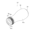
ハンドル把手23は、図3から図6に示すように、把手軸22に回転自在かつ軸方向移動不能に装着される合成樹脂製の筒状部31と、筒状部31の外周側を覆うように接着固定されたコルク製の把手部32と、把手部32の先端部の開口を閉塞するためのキャップ部材33と、筒状部31の基端部に外側面が露出するように装着され外側面に切削加工が施されたアルミニウム合金製の環状部34とを有している。
As shown in FIGS. 3 to 6, the
筒状部31は、図3から図6に示すように、把手軸22の外周側に回転自在に装着された本体筒部31aと、本体筒部31aのハンドルアーム21側(図3左側)端部外周に形成され本体筒部31aを回り止めするための回り止め部31bと、本体筒部31aのハンドルアーム21と逆側(図3右側)端部に開口するように形成された雌ねじ部31cと、本体筒部31aの外周部に突出して形成された凸部31dと、本体筒部31aの内周部にインサート成形された筒部31eとを有している。
As shown in FIGS. 3 to 6, the
本体筒部31aは、EVA樹脂等の硬質樹脂製の筒状部材であって、筒部31eのインサート成形によって一体成形されている。本体筒部31aの内周には、軸受30a、30bが装着されており、この軸受30a、30bによって把手軸22に対して筒状部31が回転自在となっている。
The main
回り止め部31bは、本体筒部31aの基端部(図3左側)外周に本体筒部31aの他の部分より大径になるように一体成形されており、後述する環状部34を装着したときに環状部34の内周側に形成された非円形孔34aに係合するように、外形形状が八角形となる非円形に形成されており、
雌ねじ部31cは、本体筒部31aの先端部(図3右側)内周に形成されたねじ孔であって、後述するキャップ部材33の雄ねじ部33aが螺合可能である。
The
The
凸部31dは、図3及び図4に示すように、本体筒部31aの軸方向(長手方向)に沿って形成され、図6に示すように、周方向に等間隔に8箇所に並べて配置された突出部である。ここでは、凸部31dによって、後述する把手部32の把手本体32aを圧入したときに、把手本体32aの内周に凸部31dの外周部が接触することにより、把手本体32aを本体筒部31aに対して回り止め及び抜け止めを行うことができる。
As shown in FIGS. 3 and 4, the
筒部31eは、アルミニウム合金を切削加工して形成された筒状部材であって、本体筒部31aの内周部にインサート成形されている。ここでは、筒部31eによって、全体の軽量化を図りながら、本体筒部31aの変形を抑えることができる。
The
把手部32は、図3から図6に示すように、回転軸に沿った方向の長さが回転軸の径方向に沿った長さより長い扁平棒状の筒状部材である把手本体32aを有している。把手本体32aは、本体筒部31aの外周側に本体筒部31aの先端部(図3右側)から本体筒部31aの基端部(図3左側)に向かって回り止め部31bに接触するように接着固定される筒状部材である。把手本体32aは、コルクによって形成されており、本体筒部31aの先端部から環状部34の先端部に向けて本体筒部31aの外周部に圧入されている。把手本体32aの内周部と本体筒部31aの外周部との間には接着剤が塗布されており、本体筒部31aに把手本体32aが固定されている。把手本体32aは、回転軸方向の中心部分が狭まった形状であり、その対向する周面に回転軸方向に沿って滑らかに内側に湾曲したつまみ面が形成されている。つまみ面は、つまんだときに手の指先にフィットするように変形矩形状に形成されている。把手本体32aは、切断方向によって厚みが異なる偏平形状となっており、また、把手軸22を挟んで対称形状となっている。把手本体32aの先端部(図3右側)の開口には、この開口を閉塞するためのキャップ部材33が装着されている。
As shown in FIGS. 3 to 6, the
キャップ部材33は、図3から図5に示すように、筒状部31の先端部(図3右側)内周部の雌ねじ部31cに螺合可能な雄ねじ部33aと、雄ねじ部33aの外径より大径に形成され雄ねじ部33aの開口を閉塞するように把手本体32aの先端部(図3右側)に接触可能な頭部33bと、頭部33bに形成された工具係止用の係止部33cとを有している。キャップ部材33は、ハンドル把手23を把手軸22にボルト部材28により装着した後、把手本体32aの先端部(図3右側)に装着固定される。
As shown in FIGS. 3 to 5, the
環状部34は、図3から図5に示すように、本体筒部31aの基端部に外側面が露出するように装着され外側面に切削加工が施されたアルミニウム合金製の環状部材である。環状部34の内周部には、基端部側が開口する大径の非円形孔34aと、先端部側が開口する小径の円形孔34bとが形成されている。非円形孔34aは、回り止め部31bの外形と同一形状となるように内形形状が八角形となる非円形に形成されており、環状部34を筒状部31に装着したときに、回り止め部31bと係合するようになっている。ここでは、筒状部31の非円形の回り止め部31bを、環状部34の非円形孔34aに係合させることにより、簡素な構成で両部材を相対回転不能に固定することができる。
As shown in FIGS. 3 to 5, the
環状部34の外側面には、図3から図5に示すように、筒状部31や把手部32を組み立てる前において、切削加工によって形成された切削加工部34cを有している。切削加工部34cは、外形が環状部34装着方向に沿うように凹んで形成された溝部を有している。ここでは、筒状部31や把手部32と別体のアルミニウム合金製の環状部34を切削加工することが容易になる。
As shown in FIGS. 3 to 5, the outer surface of the
環状部34の表面には、切削加工によって形成された切削加工部34cを形成した後に。陽極酸化処理であるアルマイト処理が施され、陽極酸化被膜であるアルマイト層が形成されている。ここでは、環状部34にアルマイト処理によるアルマイト層を表面に形成することによって、防食性を高めるとともに、環状部34の強度を高く維持できる。
After forming the
ハンドル組立体1は、図2に示すように、マスターギア軸10の内周部に相対回転不能に装着され先端部がマスターギア軸10の先端部より軸方向外方に突出して配置されるハンドル軸部7をさらに備えている。ハンドル軸部7は、図2に示すように、外形が矩形等の非円形に形成されており、マスターギア軸10の図示しない貫通孔に回転不能かつ軸方向移動可能に装着されている。ハンドル軸部7の端部(図2右側端部)には、内周側に図示しない雌ねじ部が形成されており、貫通孔に装着したハンドル軸部7の雌ねじ部に図示しないボルト部材の雄ねじ部を螺合させることによって、ハンドル軸部7をマスターギア軸10に対して抜け止めしている。また、ハンドル軸部7の先端部(図2左側端部)には、ハンドルアーム21がボルト部材20によって固定されている。
As shown in FIG. 2, the handle assembly 1 is attached to the inner peripheral portion of the
リール本体2は、図1及び図2に示すように、開口を有するリールボディ2aと、開口を塞ぐようにリールボディ2aに着脱自在に装着された蓋部材2bと、蓋部材2bから斜め上前方に延びる竿取付脚2cと、リールボディ2a及び蓋部材2bの後部から下部にわたって装着されるカバー部材2d(図1参照)とを有している。リールボディ2aは内部に空間を有している。
As shown in FIGS. 1 and 2, the
ロータ3は、図1に示すように、円筒部30と、円筒部30の側方に互いに対向して設けられた第1ロータアーム31f及び第2ロータアーム32dとを有している。円筒部30と第1ロータアーム31f及び第2ロータアーム32dとは一体に成形されている。
As shown in FIG. 1, the
第1ロータアーム31fは、図1に示すように、円筒部30から外方に向けて凸状に湾曲して前方へと延びている。第1ロータアーム31fの先端外周側には、第1ベール支持部材40が揺動自在に装着されている。第1ベール支持部材40の先端には、釣り糸をスプール4に案内するためのラインローラ41が装着されている。第2ロータアーム32dは、円筒部30から外方に凸に湾曲して前方に延びている。第2ロータアーム32dの先端外周側には、第2ベール支持部材42が揺動自在に装着されている。ラインローラ41と第2ベール支持部材42との間には、線材を略U状に湾曲させたベール43が固定されている。これらの第1ベール支持部材40、第2ベール支持部材42、ラインローラ41及びベール43によって、ベールアーム44は構成される。ベールアーム44は、糸案内姿勢とそれから反転した糸開放姿勢との間で揺動自在である。
As shown in FIG. 1, the
スプール4は、図2に示すように、ロータ3の第1ロータアーム31fと第2ロータアーム32dとの間に配置されており、スプール軸15(図2参照)の先端にドラグ機構60(図1参照)を介して装着されている。
As shown in FIG. 2, the spool 4 is disposed between the
次に、リールの操作及び動作について説明する。 Next, the operation and operation of the reel will be described.
釣りを行う際、キャスティングしてリール本体2から釣り糸を繰り出すために、ベールアーム44を反転させると、第1ベール支持部材40及び第2ベール支持部材42が揺動し、ベールアーム44を糸開放姿勢にすることができる。この状態で、釣竿を握る手の人差し指で釣り糸を引っかけながら釣竿をキャスティングする。すると、釣り糸は仕掛けの重さによって勢いよく前方に放出される。そして、ハンドル組立体1を糸巻き取方向に回転させると、図示しないロータ駆動機構によりロータ3が糸巻き取方向に回転し、ベールアーム44が図示しないベール反転機構により糸巻き取位置に復帰し、釣り糸がスプール4に巻き付けられる。
When fishing, when the
このようなスピニングリールのハンドル把手23では、合成樹脂製の筒状部31と、筒状部31や把手部32と別体で設けられ外側面に切削加工が施されたアルミニウム合金製の環状部34とを備えている。ここでは、ハンドルアーム21と把手部32との間にアルミニウム合金製の環状部34が設けられているので、長年の使用によってがたつきが生じたとしても、アルミニウム合金製の環状部34がハンドルアーム21に接触するだけで把手部32の基端部がハンドルアーム21に接触することがなくなる。したがって、把手部32がコルクにより形成されている場合でも、把手部32の基端部がハンドルアーム21に接触しないことによって、ハンドル把手23の滑らかな回転を維持しながら、アルミニウム合金製の環状部34によって、ハンドル把手23の磨耗を抑えることができる。したがって、ハンドル把手23の滑らかな回転を維持しながら、ハンドル把手23の磨耗を抑えることができる。
In such a
〔他の実施形態〕
(a) 前記実施形態では、スピニングリールを例にあげて説明したが、図12に示す両軸受リールや、図13に示す片軸受リール等の他形式の釣り用リールのハンドル把手にも本発明を適用できる。また、ハンドルつまみは、ダブルハンドルのものに限定されず、シングルハンドルのものにも本発明を適用できる。
[Other Embodiments]
(A) In the above embodiment, the spinning reel has been described as an example. However, the present invention is applicable to handle handles of other types of fishing reels such as the double-bearing reel shown in FIG. 12 and the single-bearing reel shown in FIG. Can be applied. The handle knob is not limited to a double handle, and the present invention can be applied to a single handle.
本発明の他の実施形態を採用した両軸受リールは、図12に示すように、ベイトキャスト用のロープロフィール型のリールである。この両軸受リールは、リール本体101と、リール本体101の側方に配置されたスプール回転用のハンドル組立体102と、リール本体101の内部に回転自在かつ着脱自在に装着された糸巻き用のスプール112とを備えている。ハンドル組立体102のリール本体101側には、ドラグ調整用のスタードラグ103が設けられている。
As shown in FIG. 12, a dual-bearing reel employing another embodiment of the present invention is a low profile reel for bait casting. The dual-bearing reel includes a reel
リール本体101は、フレーム105と、フレーム105の両側方に装着された第1側カバー106a及び第2側カバー106bとを有している。また、リール本体101は、フレーム105の前方を覆う前カバー107と、上部を覆うサムレスト108とを有している。フレーム105は、左右に所定の間隔をあけて互いに対向するように配置された1対の第1側板105a及び第2側板105bと、これらの第1側板105a及び第2側板105bを連結する図示しない複数の連結部とを有している。フレーム105は、下側の連結部に設けられた図示しない竿装着部により釣竿に装着可能である。
The
リール本体101の内部には、釣竿と交差する方向に配置されたスプール112と、スプール112に釣り糸を均一に巻き取るための図示しないレベルワインド機構と、ハンドル組立体1の回転をスプールに伝達する図示しない回転伝達機構とが配置されている。回転伝達機構には、ハンドル組立体102が先端に装着されたハンドル軸120と、ハンドル組立体102の回転をスプール112に伝達、遮断(オン、オフ)する図示しないクラッチ機構と、図示しないドラグ機構とが設けられている。ハンドル軸120は、リール本体101に回転自在に支持されている。フレーム105の後部には、クラッチ機構をオン、オフ操作するとともに、サミングの当てとなるクラッチレバー117が揺動自在に装着されている。
Inside the
ハンドル組立体102は、ハンドル軸120の先端に装着されるハンドルアーム121と、ハンドルアーム121の先端に装着されたハンドル把手123とを備えている。ハンドル把手123は、把手軸122に回転自在かつ軸方向移動不能に装着される合成樹脂製の筒状部131と、筒状部131の外周側を覆うように接着固定されたコルク製の把手部132と、把手部132の先端部の開口を閉塞するためのキャップ部材133と、筒状部131の基端部に外側面が露出するように装着され外側面に切削加工が施されたアルミニウム合金製の環状部134とを有している。なお、ハンドル把手123の構成は、前記実施形態の図番に100を加えたものと同様であるので、詳細な説明は省略する。
The
このような両軸受リールのハンドル把手123は、前記実施形態と同様に、合成樹脂製の筒状部131と、筒状部131や把手部132と別体で設けられ外側面に切削加工が施されたアルミニウム合金製の環状部134とを備えているので、ハンドル把手123の滑らかな回転を維持しながら、ハンドル把手123の磨耗を抑えることができる。
The
本発明の他の実施形態を採用した片軸受リールは、図13に示すように、リール本体201と、リール本体201に片持ち支持されたスプール軸202と、スプール軸202に対して相対回転自在に配置され外周に釣り糸が巻かれるスプール203とを備えている。スプール203は、筒状の糸巻胴部215と、糸巻胴部215の一端部に糸巻胴部215と一体で形成された円板状の内フランジ216と、糸巻胴部215の他端部にリール本体201の開放部を覆うように装着された外フランジ217とを有している。外フランジ217の外面で外周近くにはハンドル把手223が取り付けられている。ハンドル把手223は、把手軸222に回転自在かつ軸方向移動不能に装着される合成樹脂製の筒状部231と、筒状部231の外周側を覆うように接着固定されたコルク製の把手部232と、把手部232の先端部の開口を閉塞するためのキャップ部材233と、筒状部231の基端部に外側面が露出するように装着され外側面に切削加工が施されたアルミニウム合金製の環状部234とを有している。なお、ハンドル把手223の構成は、前記実施形態の図番に200を加えたものと同様であるので、詳細な説明は省略する。
As shown in FIG. 13, a single-bearing reel employing another embodiment of the present invention includes a
このような片軸受リールのハンドル把手223は、前記実施形態と同様に、合成樹脂製の筒状部231と、筒状部231や把手部232と別体で設けられ外側面に切削加工が施されたアルミニウム合金製の環状部234とを備えているので、ハンドル把手223の滑らかな回転を維持しながら、ハンドル把手223の磨耗を抑えることができる。
The
(b) 前記実施形態では、筒状部31は、硬質樹脂製の本体筒部31aに金属製の筒部31eがインサート成形されていたが、金属製の筒部を設けない構成にしてもよい。また、筒状部31の材質はこれらに限定されるものではなく、EVA樹脂以外の合成樹脂により形成してもよい。
(B) In the said embodiment, although the
(c) 前記実施形態では、切削加工部34cは、環状部34装着方向に沿うように凹んで形成された溝部であったが、これに限定されるものではない。切削加工部34cは、たとえば、図7に示すように、外形が周方向に沿うように凹んで形成された溝部であってもよいし、図8に示すように、ローレット加工によって形成されたぎざぎざ模様の溝部であってもよい。
(C) In the said embodiment, although the cutting
(d) 前記実施形態では、把手部32は、1つの部材によって形成されていたが、図9に示すように、基端部側に配置された第1把手部32bと、先端部側に配置された第1把手部32bと異なる材質によって異なる色に形成された第2把手部32cとを有する構成にしてもよい。さらに、図9に示すように、第2把手部32cは、外側面に蛍光色となる塗装処理が施されていてもよい。
(D) In the embodiment, the
(e) 前記実施形態では、把手部32は、コルクによって形成されていたが、把手部32の材質はこれらに限定されるものではなく、図10に示すように、たとえばエラストマーやクロロプレンゴム等の合成樹脂ウレタンゴムや軟質塩化ビニル(PVC)等の弾性体樹脂によって形成してもよいし、図11に示すように、アルミニウム合金によって形成してもよい。
(E) In the said embodiment, although the
1 ハンドル組立体
2 リール本体
3 ロータ
4 スプール
21 ハンドルアーム
22 把手軸
23 ハンドル把手
31 筒状部
31a 本体筒部
31b 回り止め部
31c 雌ねじ部
31d 凸部
31e筒部
32 把手部
32a 把手本体
32b 第1把手部
32c 第2把手部
33 キャップ部材
33a 雄ねじ部
33b 頭部
33c 係止部
34 環状部
34a 非円形孔
34b 円形孔
34c 切削加工部
DESCRIPTION OF SYMBOLS 1
Claims (13)
前記把手軸の外周側に回転自在に装着された合成樹脂製の筒状部と、
前記筒状部の基端部に外側面が露出するように装着され、前記外側面に切削加工が施された金属製の環状部と、
前記筒状部の先端部から前記環状部の先端部に向けて前記筒状部の外周部に装着された把手部と、
を備え、
前記筒状部は、基端部に他の部分の外径より大径となるようにかつ外形が非円形となるように形成された係合部を有しており、
前記環状部は、内形が非円形となるように形成され、前記係合部が係合可能な被係合部を有しており、
前記係合部及び前記被係合部の係合によって、前記環状部は、前記筒状部の基端部に相対回転不能に固定され、且つ前記筒状部の前記係合部と前記把手部とによって挟持される、
釣り用リールのハンドル把手。 A handle handle rotatably mounted on a handle shaft fixed to the tip of a handle arm of a fishing reel,
A cylindrical portion made of synthetic resin rotatably mounted on the outer peripheral side of the handle shaft;
An annular portion made of metal that is mounted so that the outer surface is exposed at the base end portion of the cylindrical portion, and the outer surface is cut.
A grip portion attached to an outer peripheral portion of the tubular portion from the distal end portion of the tubular portion toward the distal end portion of the annular portion;
With
The cylindrical portion has an engagement portion formed at the base end portion so as to have a larger diameter than the outer diameter of other portions and the outer shape is non-circular,
The annular portion is formed so that the inner shape is non-circular, and has an engaged portion with which the engaging portion can be engaged,
By the engagement of the engaging portion and the engaged portion, the annular portion is fixed to the base end portion of the cylindrical portion so as not to be relatively rotatable, and the engaging portion and the handle portion of the cylindrical portion are fixed. Sandwiched between and
Handle handle for fishing reel.
請求項1に記載の釣り用リールのハンドル把手。 The annular portion has a groove portion formed so as to be recessed so that the outer shape is along the circumferential direction.
The handle handle of the fishing reel according to claim 1 .
請求項1又は2に記載の釣り用リールのハンドル把手。 The annular portion is knurled on the outer surface,
The handle handle of the fishing reel according to claim 1 or 2 .
請求項1から3のいずれか1項に記載の釣り用リールのハンドル把手。 The annular portion is bonded to the proximal end portion of the cylindrical portion,
The handle handle of the fishing reel according to any one of claims 1 to 3 .
請求項1から4のいずれか1項に記載の釣り用リールのハンドル把手。 The grip portion is press-fitted into the outer peripheral portion of the cylindrical portion,
The handle handle of the fishing reel according to any one of claims 1 to 4 .
請求項1から5のいずれか1項に記載の釣り用リールのハンドル把手。 The handle portion is formed of either synthetic resin or cork.
The handle handle of the fishing reel according to any one of claims 1 to 5 .
請求項1から6のいずれか1項に記載の釣り用リールのハンドル把手。 The handle portion includes a first handle portion disposed on the base end portion side and a second handle portion formed of a material different from that of the first handle portion disposed on the distal end portion side.
The handle handle of the fishing reel according to any one of claims 1 to 6 .
請求項7に記載の釣り用リールのハンドル把手。 The second handle portion has been subjected to a coating process that becomes a fluorescent color on the outer surface,
The handle handle of the fishing reel according to claim 7 .
請求項1から8のいずれか1項に記載の釣り用リールのハンドル把手。 The annular portion is made of an aluminum alloy.
The handle handle of the fishing reel according to any one of claims 1 to 8 .
請求項1から9のいずれか1項に記載の釣り用リールのハンドル把手。 The annular portion has an anodized film formed on the surface by anodization,
A handle handle for a fishing reel according to any one of claims 1 to 9 .
請求項1から10のいずれか1項に記載の釣り用リールのハンドル把手。 The fishing reel is a spinning reel.
The handle handle of the fishing reel according to any one of claims 1 to 10 .
請求項1から10のいずれか1項に記載の釣り用リールのハンドル把手。 The fishing reel is a dual-bearing reel,
The handle handle of the fishing reel according to any one of claims 1 to 10 .
請求項1から10のいずれか1項に記載の釣り用リールのハンドル把手。 The fishing reel is a single bearing reel,
The handle handle of the fishing reel according to any one of claims 1 to 10 .
Priority Applications (4)
| Application Number | Priority Date | Filing Date | Title |
|---|---|---|---|
| JP2008117611A JP5205120B2 (en) | 2008-04-28 | 2008-04-28 | Handle handle for fishing reel |
| KR20090017836A KR101488151B1 (en) | 2008-04-28 | 2009-03-03 | Handle knob for fishing reel |
| TW098110736A TWI479992B (en) | 2008-04-28 | 2009-03-31 | The handle of the lever with the reel |
| CN2009101326943A CN101569298B (en) | 2008-04-28 | 2009-04-07 | Handle for fishing wheel |
Applications Claiming Priority (1)
| Application Number | Priority Date | Filing Date | Title |
|---|---|---|---|
| JP2008117611A JP5205120B2 (en) | 2008-04-28 | 2008-04-28 | Handle handle for fishing reel |
Publications (3)
| Publication Number | Publication Date |
|---|---|
| JP2009261367A JP2009261367A (en) | 2009-11-12 |
| JP2009261367A5 JP2009261367A5 (en) | 2011-05-19 |
| JP5205120B2 true JP5205120B2 (en) | 2013-06-05 |
Family
ID=41228894
Family Applications (1)
| Application Number | Title | Priority Date | Filing Date |
|---|---|---|---|
| JP2008117611A Active JP5205120B2 (en) | 2008-04-28 | 2008-04-28 | Handle handle for fishing reel |
Country Status (4)
| Country | Link |
|---|---|
| JP (1) | JP5205120B2 (en) |
| KR (1) | KR101488151B1 (en) |
| CN (1) | CN101569298B (en) |
| TW (1) | TWI479992B (en) |
Families Citing this family (10)
| Publication number | Priority date | Publication date | Assignee | Title |
|---|---|---|---|---|
| JP3164243U (en) * | 2010-09-08 | 2010-11-18 | 広明 舟岡 | Fishing reel assembly handle |
| KR101282412B1 (en) * | 2012-01-03 | 2013-07-04 | 주식회사 도요엔지니어링 | Knob assembly for fishing reel |
| KR102005125B1 (en) * | 2012-05-29 | 2019-07-29 | 글로브라이드 가부시키가이샤 | Spinning fishing reel |
| JP2015047108A (en) * | 2013-08-30 | 2015-03-16 | グローブライド株式会社 | Knob of fishing reel and assembling method |
| JP2015047109A (en) * | 2013-08-30 | 2015-03-16 | グローブライド株式会社 | Knob of fishing reel |
| JP6956602B2 (en) * | 2017-11-13 | 2021-11-02 | 株式会社シマノ | Handle knob of fishing reel and reel for fishing |
| CN108515995A (en) * | 2018-04-27 | 2018-09-11 | 天津市友森金属结构有限公司 | A kind of convenient and practical heat preservation table trolley |
| KR102118292B1 (en) | 2019-12-03 | 2020-06-02 | 주식회사 샤크컴퍼니 | Apparetus to fix handle for preventing release of fishing reel |
| KR200495872Y1 (en) | 2020-03-17 | 2022-09-06 | 주식회사 바낙스 | Center shaft variable power handle for bait reel |
| KR20230100351A (en) | 2021-12-28 | 2023-07-05 | 주식회사 바낙스 | Lightweight structure of handle knob of fishing reel |
Family Cites Families (9)
| Publication number | Priority date | Publication date | Assignee | Title |
|---|---|---|---|---|
| JPS5745804Y2 (en) * | 1979-12-06 | 1982-10-08 | ||
| JP3593407B2 (en) * | 1996-01-24 | 2004-11-24 | 株式会社シマノ | Reel handle |
| JP3977730B2 (en) * | 2002-12-03 | 2007-09-19 | 株式会社シマノ | Fishing reel parts |
| JP2004236541A (en) * | 2003-02-04 | 2004-08-26 | Daiwa Seiko Inc | Handle of reel for fishing |
| JP2006238746A (en) * | 2005-03-01 | 2006-09-14 | Shimano Inc | Handle grip of fishing reel |
| SG121940A1 (en) * | 2004-10-06 | 2006-05-26 | Shimano Kk | Handle knob and handle assembly for a fishing reel |
| JP4704801B2 (en) * | 2005-04-28 | 2011-06-22 | 株式会社シマノ | Handle handle for fishing reel |
| JP5010860B2 (en) * | 2006-06-30 | 2012-08-29 | 株式会社シマノ | Handle handle for fishing reel |
| JP5236883B2 (en) * | 2007-02-13 | 2013-07-17 | シマノコンポネンツ マレーシア エスディーエヌ.ビーエッチディー. | Spinning reel handle assembly |
-
2008
- 2008-04-28 JP JP2008117611A patent/JP5205120B2/en active Active
-
2009
- 2009-03-03 KR KR20090017836A patent/KR101488151B1/en active IP Right Grant
- 2009-03-31 TW TW098110736A patent/TWI479992B/en active
- 2009-04-07 CN CN2009101326943A patent/CN101569298B/en active Active
Also Published As
| Publication number | Publication date |
|---|---|
| JP2009261367A (en) | 2009-11-12 |
| TW201012390A (en) | 2010-04-01 |
| CN101569298B (en) | 2013-03-13 |
| CN101569298A (en) | 2009-11-04 |
| TWI479992B (en) | 2015-04-11 |
| KR101488151B1 (en) | 2015-01-30 |
| KR20090113756A (en) | 2009-11-02 |
Similar Documents
| Publication | Publication Date | Title |
|---|---|---|
| JP5205120B2 (en) | Handle handle for fishing reel | |
| JP2009261367A5 (en) | ||
| US9091350B2 (en) | Spinning reel waterproofing member and spinning reel using the same | |
| US8678308B2 (en) | Dual-bearing reel drag sound producing device | |
| US6598819B2 (en) | Spinning-reel spool | |
| KR102235551B1 (en) | Line roller and fishing line guide mechanism using same | |
| JP2007189982A (en) | Gear part-fitting structure for fishing reel | |
| JP2007189982A5 (en) | ||
| JP4045167B2 (en) | Spinning reel handle assembly | |
| JP6027805B2 (en) | Spinning reel handle assembly | |
| KR20060090574A (en) | Spinning reel handle assembly | |
| JP2014064487A5 (en) | ||
| JP2014140350A (en) | Double bearing reel | |
| JP4015957B2 (en) | Spinning reel handle assembly | |
| JP2014023432A5 (en) | ||
| JP2014223054A (en) | Line roller and fishing line guide mechanism using the same | |
| JP5869240B2 (en) | Handle handle for fishing reel | |
| JP5010860B2 (en) | Handle handle for fishing reel | |
| JP5956799B2 (en) | Double-bearing reel and drag operation member for double-bearing reel | |
| JP4704801B2 (en) | Handle handle for fishing reel | |
| JP2006238746A (en) | Handle grip of fishing reel | |
| JP4476128B2 (en) | Spinning reel master gear | |
| JP5185177B2 (en) | Spindle reel handle mounting structure | |
| JP2006129864A (en) | Handle knob and handle assembly of fishing reel | |
| JP4572124B2 (en) | Handle handle for fishing reel |
Legal Events
| Date | Code | Title | Description |
|---|---|---|---|
| A521 | Request for written amendment filed |
Free format text: JAPANESE INTERMEDIATE CODE: A523 Effective date: 20110328 |
|
| A621 | Written request for application examination |
Free format text: JAPANESE INTERMEDIATE CODE: A621 Effective date: 20110328 |
|
| A977 | Report on retrieval |
Free format text: JAPANESE INTERMEDIATE CODE: A971007 Effective date: 20120427 |
|
| A131 | Notification of reasons for refusal |
Free format text: JAPANESE INTERMEDIATE CODE: A131 Effective date: 20120508 |
|
| A521 | Request for written amendment filed |
Free format text: JAPANESE INTERMEDIATE CODE: A523 Effective date: 20120626 |
|
| TRDD | Decision of grant or rejection written | ||
| A01 | Written decision to grant a patent or to grant a registration (utility model) |
Free format text: JAPANESE INTERMEDIATE CODE: A01 Effective date: 20130205 |
|
| A61 | First payment of annual fees (during grant procedure) |
Free format text: JAPANESE INTERMEDIATE CODE: A61 Effective date: 20130218 |
|
| R150 | Certificate of patent or registration of utility model |
Ref document number: 5205120 Country of ref document: JP Free format text: JAPANESE INTERMEDIATE CODE: R150 Free format text: JAPANESE INTERMEDIATE CODE: R150 |
|
| FPAY | Renewal fee payment (event date is renewal date of database) |
Free format text: PAYMENT UNTIL: 20160222 Year of fee payment: 3 |
|
| R250 | Receipt of annual fees |
Free format text: JAPANESE INTERMEDIATE CODE: R250 |
|
| R250 | Receipt of annual fees |
Free format text: JAPANESE INTERMEDIATE CODE: R250 |
|
| R250 | Receipt of annual fees |
Free format text: JAPANESE INTERMEDIATE CODE: R250 |
|
| R250 | Receipt of annual fees |
Free format text: JAPANESE INTERMEDIATE CODE: R250 |
|
| R250 | Receipt of annual fees |
Free format text: JAPANESE INTERMEDIATE CODE: R250 |
|
| R250 | Receipt of annual fees |
Free format text: JAPANESE INTERMEDIATE CODE: R250 |
|
| R250 | Receipt of annual fees |
Free format text: JAPANESE INTERMEDIATE CODE: R250 |
|
| R250 | Receipt of annual fees |
Free format text: JAPANESE INTERMEDIATE CODE: R250 |
|
| R250 | Receipt of annual fees |
Free format text: JAPANESE INTERMEDIATE CODE: R250 |