CN101496121A - Inductive sensor - Google Patents
Inductive sensor Download PDFInfo
- Publication number
- CN101496121A CN101496121A CNA2007800260990A CN200780026099A CN101496121A CN 101496121 A CN101496121 A CN 101496121A CN A2007800260990 A CNA2007800260990 A CN A2007800260990A CN 200780026099 A CN200780026099 A CN 200780026099A CN 101496121 A CN101496121 A CN 101496121A
- Authority
- CN
- China
- Prior art keywords
- inductor
- sensor material
- change
- coil
- transducer
- Prior art date
- Legal status (The legal status is an assumption and is not a legal conclusion. Google has not performed a legal analysis and makes no representation as to the accuracy of the status listed.)
- Pending
Links
Images


Classifications
-
- H—ELECTRICITY
- H01—ELECTRIC ELEMENTS
- H01F—MAGNETS; INDUCTANCES; TRANSFORMERS; SELECTION OF MATERIALS FOR THEIR MAGNETIC PROPERTIES
- H01F21/00—Variable inductances or transformers of the signal type
- H01F21/02—Variable inductances or transformers of the signal type continuously variable, e.g. variometers
-
- H—ELECTRICITY
- H01—ELECTRIC ELEMENTS
- H01F—MAGNETS; INDUCTANCES; TRANSFORMERS; SELECTION OF MATERIALS FOR THEIR MAGNETIC PROPERTIES
- H01F21/00—Variable inductances or transformers of the signal type
- H01F21/005—Inductances without magnetic core
Abstract
An inductive sensor includes an inductor having one or more loops and a sensor material configured to respond to a parameter of interest by a dimensional change of the sensor material. The sensor material is oriented within the loops of the inductor so that the dimensional change of the sensor material produces a dimensional change of the inductor. The dimensional change of the inductor alters the inductance of the inductor.
Description
Technical field
The present invention relates to inductance type transducer, it has the sensor material that is arranged in the inductor coil.
Background technology
Transducer is converted into the variation of outside stimulus and can detects or the variation of measurable sensor parameter.In multiple concrete enforcement, can use the passive electronic device such as inductor, capacitor and/or resistor to form transducer.The circuit values of these transducers (as inductance, electric capacity or resistance value) changes with the variation of relevant parameter.These transducers can be compounded in the sensor circuit, so that the circuit parameter variations that is caused by the associated change parameter changes sensor circuit output.
Usually expect the remote collection sensor information.Radio-frequency (RF) identification (RFID) circuit has been used to detect the existence and the motion of correlated product.The remote access capability of RFID technology can be combined with sensor technology, so that the remote sensing ability to be provided.The present invention has satisfied these needs and other needs, and other advantages above prior art are provided.
Summary of the invention
The present invention relates to respond the inductance type transducer of relevant parameter, this inductance type transducer comprises inductor and is arranged on the sensor material of the size variable in the inductor coil.
One embodiment of the present of invention relate to inductance type transducer.This inductance type transducer comprises and contains one or more coils and the inductor relevant with inductance.Inductance type transducer comprises sensor material, and this sensor material is constructed to by the change in size of sensor material relevant parameter be responded.Sensor material is located in the inductor coil, makes the change in size of sensor material cause the change in size of inductor.The change in size of inductor changes the inductance of inductor.
According to an aspect, sensor material is located so that the change in size of sensor material causes the change of inductor cross-sectional area.According to another aspect of the present invention, sensor material is located so that the change in size of sensor material causes the change of inductor length.Another aspect relates to sensor material location, so that the change in size of sensor material causes the change of distance between two or more coils of inductor.In yet another aspect, sensor material is arranged between at least two coils of inductor, and the change in size of sensor material can cause the change of distance between at least two coils.
Sensor material can comprise polymer, and this polymer can respond the variation of relevant parameter and expand or shrink.In a kind of structure, sensor material comprises hydrogel.
Sensor material can be constructed in temperature, humidity, pH value, fluid stream, salinity, solvent composition, concentration of glucose, electric field, light and the ion concentration one or more are responded.
In concrete an enforcement, transducer comprises capacitor, and this capacitor electrode is coupled to inductor to form resonant circuit, and wherein, the variation of relevant parameter can cause the change of the resonance characteristic of this resonant circuit.
For example, in the coil of inductor at least one can be arranged on the flexible base, board, and the change in size of inductor comprises the bending of flexible base, board and this at least one coil.Inductance type transducer can comprise locking mechanism, and this locking mechanism is constructed at least one coil with respect to another coil initial alignment at least.
An alternative embodiment of the invention relates to sensing system.This sensing system comprises inductance type transducer, and this inductance type transducer has the inductor that comprises one or more coils.Sensor material is constructed to respond with relevant parameter by the change in size of this sensor material.Sensor material is positioned in the zone that is limited by inductor coil, so that the change in size of sensor material can cause the change in size of the inductor that is caused by the change of inductor current.Sensing system also comprises sensor circuit, this sensor circuit and inductor electric coupling, the resonant circuit that has the resonance characteristic that depends on inductance with formation.The query device is configured to detect the change of the resonance characteristic of resonant circuit, and can analyze the relevant parameter based on resonance characteristic.For example, resonance characteristic can be the resonance frequency of inductance type transducer.In concrete an enforcement, the query device is configured to the resonance frequency of radio detection inductance type transducer.
Sensing system can comprise reference circuit, and it is constructed to produce can be by the detected reference signal of query device.In this structure, the query device can be constructed to use reference signal to proofread and correct by the error in the signal of inductance type transducer generation.
According to concrete an enforcement, inductance type transducer be set on the suction dressing or within, this dressing is configured to be placed on one's body the patient.Relevant parameter is a moisture.The resonance characteristic based on inductance type transducer of being constructed to the query device detects the moisture in the dressing.
Above general introduction of the present invention is not to be intended to describe each embodiment of the present invention or every kind of concrete enforcement of the present invention.In conjunction with the accompanying drawings, with reference to embodiment and appended claims hereinafter, combination is to the more complete understanding of the present invention again, and advantage of the present invention and effect will become apparent and be comprehended by the people.
Description of drawings
Figure 1A and Figure 1B show end view and the cutaway view that shows respectively according to the inductance type transducer of the embodiment of the invention, and this inductance type transducer combines with the sensor material that can size responds in initial condition or before relevant parameter changes;
Fig. 1 C and Fig. 1 D show end view and the cutaway view according to the inductance type transducer of the embodiment of the invention respectively, and this inductance type transducer combines with the sensor material that can size responds in state of termination or in the relevant parameter back that changed;
Fig. 2 A shows the hinged inductance type transducer according to the embodiment of the invention, and it does not have sensor material;
Fig. 2 B and Fig. 2 C show according to embodiment of the invention structure can the size response the power that sensor material produced;
Fig. 3 A shows according to the embodiment of the invention after with coil location and the hinge-less of the inductance type transducer after being arranged on sensor material between substrate structure.
Fig. 3 B shows the substrate of inductance type transducer of no sensor material and the plane graph of coil.
Fig. 3 C and Fig. 3 D be according to the embodiment of the invention before the sensor material change in size and the schematic cross sectional views of inductance type transducer afterwards;
Fig. 4 A is after being illustrated in the inductance type transducer that is constructed to moisture transducer and being exposed in the water, the inductance time history plot:
Fig. 4 B is the curve chart that the thermal effectiveness of some sensor material is shown;
Fig. 4 C illustrates the curve chart of two kinds of hydrogels with the expansion curve of pH variation;
Fig. 5 A is the schematic diagram that is used for the resonant circuit of RFID application.
Fig. 5 B is the schematic diagram according to the resonant circuit of the embodiment of the invention, and this resonant circuit combines inductance type transducer;
Fig. 6 A shows the schematic cross sectional views according to the resonant circuit/transducer of the embodiment of the invention.
Fig. 6 B shows the resonant circuit components and the substrate of the resonant circuit/transducer that does not have sensor material among Fig. 6 A in the mode of plane graph;
Fig. 6 C shows the resonant circuit/transducer according to the embodiment of the invention, and it comprises segmented electrode for capacitors and perforation in the substrate;
Fig. 6 D and Fig. 6 E show according to the embodiment of the invention respectively, electrically connect as the inductance type transducer of minus device and eurymeric device;
Fig. 7 A shows the resonant circuit/transducer according to the embodiment of the invention, and it has inductor, and this inductor has a plurality of ceoncentrically wound coils that are arranged on the single collapsible substrate;
Fig. 7 B shows the resonant circuit/transducer according to the embodiment of the invention, and it comprises inductor, and this inductor has a plurality of coils that are formed on five flexible foldable substrate portion;
Fig. 8 is the block diagram according to the remote sensing system of the embodiment of the invention;
Fig. 9 shows the query device by the curve chart that obtains the signal that frequency sweep produces respectively at t1 and t2 on the time, and this figure has pointed out moving down in the resonance frequency of resonant circuit;
Figure 10 shows the curve chart that resonance frequency changes with the distance between the inductor coil.
Figure 11 A shows according to the curve chart of the embodiment of the invention at the wetting back of the resonant circuit/transducer that will be constructed to moisture transducer resonance frequency time to time change;
Figure 11 B shows according to the resonant circuit of the embodiment of the invention curve chart with respect to the frequency change of pH, and this resonant circuit comprises inductance type transducer, and this inductance type transducer has adopted a kind of concrete preparation of hydrogel sensor material;
Figure 12 is the block diagram according to the remote sensing system of the embodiment of the invention, and this system combines reference circuit and sensor circuit;
Figure 13 A is the schematic diagram according to the sensing system of the embodiment of the invention, and this system comprises resonance reference circuit and resonant transducer circuit;
Figure 13 B is the curve chart that the signal that is produced by the frequency sweep that obtains in t1 and t2 time respectively according to the query device of the embodiment of the invention is shown, and this curve chart has been pointed out the displacement of the stable resonant oscillation frequency and the sensor circuit resonance frequency of reference circuit;
Figure 14 A-14C shows the technology that is used to prepare inductance type transducer according to the embodiment of the invention;
Figure 15 A-15H shows according to the embodiment of the invention and uses photoetching technique to prepare the technology of inductance type transducer;
Figure 16 A-16C shows the inductance type transducer according to the embodiment of the invention, and it comprises the mechanism that is used for fixation of sensor when initial alignment;
Figure 17 A-17B shows the inductance type transducer according to the embodiment of the invention, and it comprises locking mechanism;
Figure 18 A-18D shows the Asymmetric Electric sensing type sensor structure according to the embodiment of the invention, and this structure provides the leverage that enlarges the sensor material displacement;
Figure 19 shows the technology that is used to prepare inductance type transducer according to the embodiment of the invention, and it comprises the folding multi-thread coil sensor of use liquid sensor coated materials;
Figure 20 shows the wound dressing that combines inductance type transducer according to the embodiment of the invention;
Figure 21 A-21B shows the pulsating flow transducer according to the embodiment of the invention; And
Figure 22 shows the inductance type transducer according to the embodiment of the invention, and it is configured to measure the fluid stream in the passage.
Though the present invention can have various modification and alternative form, its concrete characteristics illustrate by way of example by accompanying drawing, and with detailed description.Yet should be appreciated that its purpose does not lie in limit the invention to described specific embodiment.On the contrary, its purpose is to contain all modifications form, equivalents and the alternative form in the scope of the invention, and the present invention only is subjected to the qualification of appended claims.
Embodiment
In the following relevant description of exemplary embodiment, the accompanying drawing with reference to forming this paper part wherein illustrates in illustrational mode and can be used to implement various embodiment of the present invention.Should be appreciated that without departing from the scope of the invention, can utilize embodiment, and can carry out structural change.
Embodiments of the invention relate to inductance type transducer, combine the method for circuit and system and the preparation and the use inductance type transducer of inductance type transducer.Method of the present invention relates to the inductance type transducer with inductance value, and this inductance value changes with concrete parameter or the condition that transducer exposed.In multiple concrete enforcement as herein described, the change of the inductance value of inductance type transducer be by around or the variation of environmental condition or relevant analyte caused.When for example, inductance value can be in being exposed to concrete analyte or variation after concrete analyte changes.The parameter that is detected or measured by inductance type transducer is also referred to as sensor parameter or relevant parameter in this article usually.Use detects, measures according to the inductance type transducer of embodiment described herein and/or the exemplary lists of the sensor parameter of monitoring comprises: for example temperature, humidity, pH value, fluid stream, salinity, solvent composition, concentration of glucose, electric field, light and ion concentration.
In some concrete enforcement, inductance type transducer combines the sensor material that is positioned, so that the change in size of sensor material causes the change in size of inductor.The change in size of inductor can cause that the inductance value of inductor changes.In some concrete enforcements, inductance type transducer comprise at least two coils and with the hinge of coil mechanical connection.Can change distance between the induction coil to the operation of hinge, and cause the corresponding change of inductor current.In other concrete enforcement, the sensor material that can present change in size when being exposed to relevant parameter is used in combination with hinged inductance type transducer.
In these and other concrete enforcements, inductance type transducer can be used as the element in the resonant circuit, so that the remote access to transducer to be provided.The inductance variation of inductance type transducer can cause the corresponding change of the resonance-characteristic of resonant circuit.Can use outside query device to come the variation of radio detection resonance characteristic.
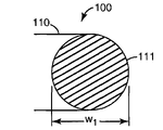
Figure 1A and Figure 1B show end view and the cutaway view according to the inductance type transducer 100 of the embodiment of the invention respectively.Inductance type transducer 100 comprises inductor 110, and inductor 110 has one or more coils 111 and relevant with inductance value.The inductance value L of inductor depends on following parameter usually: the magnetic permeability, the number of turns, the cross-sectional area of inductor and the length of inductor that are connected to the material on the inductor coil.
Figure 1A and Figure 1B show respectively at the end view and the vertical view that sense the inductance type transducer 100 under the initial condition of parameter before changing.Inductance type transducer 100 has initial construction, and it comprises initial length l
0, initial diameter w
0, initial area A
0And the initial distance d between the every pair of coil
0Fig. 1 C and Fig. 1 D show end view and the cutaway view that is exposed to the inductance type transducer 100 after parameter changes.Because the expansion of sensor material 120 has caused length l
1, diameter w
1, area A
1, or 111 of coils apart from d
1In one or more change has taken place, thereby cause corresponding expansion by 111 localized areas of inductor coil.Any or multiple variation in the distance between length, diameter, area or the inductor coil all can cause the change of inductor current value.
Sensor material is selected, to show owing to the associated sensed parameter changes the change in size that causes.For example, sensor material can expand or shrink along one or more, thereby causes that in width, length or the cross-sectional area of sensor material one or more change.A kind of especially available sensor material comprises hydrogel, for example poly-(vinyl alcohol)-poly-(acrylic acid) hydrogel, be expressed as the pVA-pAA hydrogel in this article, size can take place and change in this hydrogel owing to the variation of the environmental condition such as humidity, pH value or other parameters.
Fig. 2 A shows another embodiment of inductance type transducer.In this embodiment, sensor material is optional.The inductor coil 210,211 that can randomly form on substrate 220 connects by hinge 230.The angle θ of 210,211 of coils be can change to the operation of hinge 230, thereby the change of 210,211 distances of coil and the corresponding change of inductor current caused.Hinge 230 can comprise spring or other mechanisms, and the antagonism of this spring or other mechanisms directly or indirectly is applied to the power F in the coil 210,211 one or two.
Shown in Fig. 2 B, some embodiment can use and be arranged on by coil 210,211 formed angle θ sensor external materials 240.The change in size of sensor material 240 can be in coil 210,211 one or two on produce power Fext.In other embodiment shown in Fig. 2 C, sensor material 240 can be arranged on the inside by coil 210,211 formed angle θ.The change in size of sensor material 240 can be in coil 210,211 one or two on produce power F
Int1, F
Int2
Fig. 3 A-3D shows the hinge-less structure according to the inductance type transducer 300 of an embodiment.Fig. 3 A shows substrate 320,321 and coil 310,311 is being located afterwards and the inductance type transducer after being arranged on sensor material 330 between substrate 320,321 and the coil 310,311.Fig. 3 B shows the substrate 320,321 with sensor material and the electrical connection of coil 310,311.
Further specify as the cutaway view of Fig. 3 C and 3D, inductance type transducer 300 comprises two coils 310,311 that are respectively formed on the substrate 320,321.Sensor material 330 is set between the coil 310,311.Sensor material 330 has original depth t
0Thereby, form 310,311 of coils apart from d
0Sensor material 330 is for relevant concrete sensor parameter size sensitivity.Along with the variation of sensor parameter, sensor material 330 is expanded to thickness t
1Thereby, in 310,311 generations of coil apart from d
1Alternatively, in some concrete enforcements, sensor material 330 can be from original depth t after being exposed to sensor parameter
0Shrink, thereby coil 310,311 is drawn closer together.
Shown in Fig. 3 B, inductance type transducer 300 can be electrically connected as the eurymeric device, the electric current of wherein going up in coil 310 and the lower coil 311 flows to same direction.The magnetic field that is produced by the coil 310,311 of eurymeric device is addition, thereby produces positive mutual inductances 310,311 of coils.The total inductance of eurymeric device coil 310,311 near the time increase, and when coil 310,311 separates, reduce.
Alternatively, inductance type transducer can be electrically connected as the minus device.Electric current on the minus device in coil and the lower coil flows in the opposite direction.In this structure, reduced the magnetic field of flowing and being produced by the electric current in the relative coil by the mobile magnetic field that is produced of the electric current in the coil.The counteracting in magnetic field has produced negative mutual inductance between coil.The total inductance of minus device reduces when coil is close, and increases when coil separates.
For example, the transducer shown in Fig. 1-3 can be used for the multiple environmental condition of sensing, for example: temperature, humidity, pH value, fluid stream, salinity, solvent composition, concentration of glucose, electric field, light and ion concentration.
The inductance that the curve chart of Fig. 4 A shows 20 circle copper coil inductors changes, and the diameter of wire that this inductor has is about 200 μ m, the about 6mm of loop length, the about 6mm of coil diameter, initial inductance L
0About 1.8 μ H.Inductor is immersed in poly-(vinyl alcohol)-poly-(acrylic acid) (pVA-pAA) in the hydrogel, so that the copper cash of water gel coating inductor.Use has the device of this structure and shows pH and moisture sensing.After the drying, the inductor that is coated with hydrogel is placed in the deionized water, and inductance measuring in time, shown in Fig. 4 A.
In the some compositions water soluble of pVA-pAA hydrogel, and need not heat treatment.For example, contain the hydrogel of 3 weight %pVA and 6 weight %PAA, it can become insoluble 130 ℃ of heat treatments 10 minutes or after the longer time, shown in Fig. 4 B.Fig. 4 B shows the correlation of heat treatment time and hydrogel expansion rate.
Through observing, the hydrogel that contains 12 weight %pVA and 1.5 weight %pAA is water insoluble under the situation of not heat-treating.The curve chart of Fig. 4 C shows the expansion curve that two kinds of hydrogels change with the pH value.Curve 410 and 411 shows respectively and comprises 3 weight %pVA and 6 weight %PAA and at the standardization expansion and the shrinkage curve of 20 minutes hydrogel of 130 ℃ of following heat treatment.Curve 420,421 shows the standardization expansion and the shrinkage curve of the hydrogel that comprises 12 weight %pVA and 1.5 weight %pAA respectively.Expand and shrinkage curve 410,411,420,421 in observable hysteresis can be used as the memory that permission detects previous expansion or contraction cycle.
In certain embodiments, inductance type transducer can with capacitor-coupled, to form tank circuits.The resonance frequency of resonant circuit and/or other resonance characteristics change with the inductance of inductance type transducer.The variation of resonance frequency and/or other resonance characteristics can detect by detector circuit, and this detector circuit is coupled to resonant circuit by wired or wireless connected mode.
Remote sensing by wireless connections especially can be used in inaccessible position and/or low-cost the application.Electronic anti-theft (EAS) or radio-frequency (RF) identification (RFID) technology have been used to detect the existence of related item and have followed the trail of moving of related item.For example, EAS and/or RFID technology are used to detect and follow the trail of the books in bookstore or the library under many circumstances.Inductance type transducer as herein described can be used as the element in the resonant circuit, and this element combines the remote access capability of sensing function and EAS or RFID technology.
Fig. 5 A is the schematic diagram that is used for the resonant circuit 510 of EAS/RFID application.Can use ball bearing made using 510 by remote access EAS/RFID device, circuit 510 comprises inductor 512 and capacitor 516 in parallel.Circuit 510 is designed to resonance when characteristic frequency, that is to say, depends on the value of circuit element 512,516.Inductor 512 plays antenna, and it is used for receiving, reflects and/or transmission electromagnetic energy, for example radio frequency (RF) energy.In some applications, additional circuit (not shown) is coupled to resonant circuit 510, to export identification code by antenna.Device that can transmission code is commonly called the RFID device.There is not the device of adjunct circuit output ID code to be commonly referred to as the EAS device.The EAS device is designed to absorb and upsets electromagnetism (EM) field, as the RF field of being sent by reader.The upset of EM field can be detected by reader, and can be resolved with the existing of indication EAS device, but the EAS device can not transmit the additional information about object usually.
According to the embodiment of the invention, comprise the inductance type transducer as resonant circuit components as described herein based on the reading circuit of EAS or RFID.Inductance type transducer is for one or more relevant parameter sensitivities.The variation of relevant parameter can cause the change of the inductance value of inductance type transducer.The resonant circuit variation inductance can cause the respective change of the resonance characteristic of resonant circuit.In multiple structure, changing the resonance characteristic of changing with inductance can comprise: other resonance characteristics of resonance frequency, Q value, bandwidth and/or resonant circuit.
The schematic diagram of Fig. 5 B has illustrated resonant circuit/transducer 520, and it comprises inductance type transducer 522 and capacitor 516.Inductance type transducer 522 is constructed to change inductance value based on relevant parameter.The variation of the inductance value of inductance type transducer 522 can cause the change of the resonance characteristic of resonant circuit/transducer 520.The change of resonance characteristic can be by RFID or EAS reader (not shown) remote detection and parsing.
Can resolve the variation of resonance frequency or other resonance characteristics, change with indication associated sensed parameter.According to some concrete enforcement, the change of resonance frequency of circuit 520 is resolved, with amount, degree or the duration of determining that sensor parameter changes.The detection that in a period of time the resonance frequency (or other characteristics) of circuit 520 is changed can be used for following the trail of the progression of sensor parameter variation certain hour in.
Fig. 6 A-6E shows a plurality of embodiment of inductance type transducer, and described inductance type transducer has two coils and forms resonant circuit with capacitor.Fig. 6 A shows the cross section, A-A from Fig. 6 B according to an embodiment ' cutaway view of resonant circuit/transducer 600 of intercepting.Inductance type transducer comprises two coils 610,611 that are arranged on the substrate 620,621.Forming first pole plate 640 of capacitor and second pole plate 641 is arranged on one of them the opposite side in the substrate 620.Relevant parameter size sensor sensitive material 630 is set between substrate 620,621 or the coil 610,611, so that the change in size of sensor material 630 causes the respective change of 610,611 distances of coil.Fig. 6 B shows resonant circuit components 610,611,640 and the substrate 620,621 with sensor material.Inductor is connected with capacitor electrode, to form resonant circuit, for example circuit shown in Fig. 5 B 520.
In certain embodiments, shown in Fig. 6 C-E, inductor coil 610,611 and capacitor plate 640 can be formed on the single folding substrate 660, and this substrate 660 comprises first 661 and second portion 662.The first 661 of substrate 660 and second portion 662 are by flexible hanger part 650 separately.The operation of flexible hanger 650 is allowed the location of inductor coil 610,611, so that they overlap each other.Can size the sensor material (not shown) of response can be with respect to coil 610,611 location so that the change in size of sensor material cause coil near or away from.Some embodiment have adopted perforation 670, touch the sensing material that is clipped between the substrate portion 661,662 to allow analyte.
One or two electrode 640 of integrating condenser can be divided into a plurality of parts 642 shown in Fig. 6 C.Electrode for capacitors 640 is divided into a plurality of parts 642 can reduces vortex flow in the electrode for capacitors 640, this vortex flow can countermeasure set 600 and query device exterior antenna between magnetic coupling.
Fig. 6 D and 6E show and are arranged as the inductance type transducer that is formed on the resonant circuit on the collapsible substrate 660 and the multiple structure of capacitor.Fig. 6 D shows the minus device, and it has capacitor plate 640, and this capacitor plate 640 is formed on the substrate portion 661 of coil 610 enclosing region outside.When substrate 660 when folding and coil 610,611 is overlapping at flexible hanger 650 places, the electric current in last coil 610 and the lower coil 611 flows round about, because the magnetic field of the mobile generation of the electric current in the bucking coil 610,611 has produced negative mutual inductance.The total inductance of minus device reduces when last coil 610 and lower coil 611 are close to each other, and increases away from each other the time at coil 610,611.
Fig. 6 E shows the eurymeric device.When substrate 660 is folded so that substrate portion 661,662 and coil 610,611 when overlapping, the electric current in the overlapping coil 610,611 flows to same direction.The total inductance of eurymeric device increases when drawing close together at coil 610,611, reduces when coil 610,611 is moved apart.
In certain embodiments, the inductor of inductance type transducer can comprise a plurality of coils, as shown in Fig. 7 A and Fig. 7 B.The use of interpole coil can improve specified inductance, and the raising of specified inductance helps realizing better inductance coupling high between transducer and the query device.Fig. 7 A shows the resonant circuit/transducer with inductor, and this inductor has a plurality of ceoncentrically wound coils 710,711 that are arranged on the single collapsible substrate 720.A plurality of ceoncentrically wound coils 710,711 are respectively formed on the substrate portion 721,722.Substrate 720 comprises the flexible hanger part 791 of 721,722 of substrate portion.When being folded, coil 710,711 is overlapping to form multi-thread circle inductor.Capacitor is formed on the substrate portion 722, and segmented capacitor plate 740 is arranged on by in 711 area surrounded of inductor coil.One or two part of substrate 721,722 can comprise perforation 790, is exposed to analyte or other sensed environmental conditions with the sensor material (not shown) that allows to be arranged on 710,711 of coils.The appropriate electrical that realizes minus or eurymeric transducer and/or formation resonant circuit connects and can obtain by using connectors 795.
In another embodiment shown in Fig. 7 B, resonant circuit/transducer 701 comprises the inductor with a plurality of coil 751-755, and these a plurality of coil 751-755 are formed on five flexible base, board part 761-765.The inductor that each substrate portion 761-765 is device 701 provides a coil 751-755.Coil 751-755 can all be formed on the side of substrate portion 761-765, or as shown, its half be formed on every side of substrate portion 761-765.Substrate portion 761-765 stacks by making device 701 sentence zigzag mode at flexible hanger 772-775, thereby form the tubular inductor of helical, this inductor and capacitor-coupled, this capacitor have the pole plate 780,781 on one of them of substrate portion of being formed on 761.The substrate portion that does not comprise capacitor plate 780,781 has through hole 766-769 alternatively.
In certain embodiments, the sensor material (not shown) is arranged between one or more substrate portion 761 to 765.If substrate portion 761-765 comprises through hole 766-769, then sensor material is along the periphery setting of substrate portion 761-765.
Use can accessing wirelessly combines the query device circuit of the resonant circuit of inductance type transducer, realizes above-mentioned remote sensing by inductance type transducer.The block diagram of Fig. 8 shows remote sensing system 850, and it comprises query device 830 (also being expressed as reader herein) and resonant circuit 820, and this resonant circuit 820 has the capacitor 826 with inductance type transducer 812 couplings.Query device 830 comprises radio frequency (RF) source 834 and harmonic analysis instrument 836.
Fig. 9 shows and interrogates the frequency scanning that device obtains respectively and the signal 910,920 that produces when time t1 and t2.In the time of near resonant circuit/transducer is present in the query device, signal 910,920 is produced by the query device.Signal 910 comprises and the original resonance frequency relevant feature 911 of resonant circuit when the time t1.After the distance between the coil of inductance type transducer increased about 200 μ m, signal 920 presented signal characteristic 921, and this signal characteristic 921 and the resonant circuit/transducer resonance frequency when time t2 is relevant.Comparison signal feature 911,921 can demonstrate the moving down of resonance frequency of about 3MHz.Figure 10 shows the curve chart with the resonance frequency of variable in distance between the inductor coil.
Transducer uses hydrogel as sensor material, and for example previously described pVA-pAA hydrogel is to allow wireless monitor moisture absorption and/or pH.Figure 11 A shows the curve chart of time dependent resonance frequency behind damping device.Because moisture is absorbed by sensor material, so the resonance frequency of transducer moves down.Result shown in Figure 11 A represents the final saturation that absorbs.The curve chart of Figure 11 B shows the change of the resonant circuit frequency that takes place along with the pH of the variation of a kind of concrete preparation of the hydrogel sensor material that uses in inductance type transducer.
In some concrete enforcements, can monitor a plurality of inductance type transducers simultaneously.For example, can be in conjunction with inductance type transducer in resonant circuit, this resonant circuit has the different resonance frequencys that help the sensor wireless monitoring.A plurality of transducers can be constructed to respond different sensor parameters or respond same sensor parameter.In certain embodiments, inductance type transducer can spatially be distributed in the relevant range.Can monitor transducer, with the information that obtains to change about the one or more sensor parameters on the relevant range.But be described among the use of the transducer of the spatial distribution of accessing wirelessly (all can be used in combination with inductance type transducer disclosed herein in many-side) the U.S. Patent application No.11/383652 that owning together, that be filed on May 16th, 2006, this paper is incorporated in this patent application by reference into.
In some concrete enforcements, the resonant circuit that combines inductance type transducer as described herein, the signal of its generation can change by multiple condition, the inductance coupling high between this multiple condition influence reading circuit and the query device and/or the electrical characteristics of circuit.For example, sensor signal can be subjected to the factor affecting except that the associated sensed parameter, for example the distance between location and/or sensor circuit and query device, electromagnetic interference, adjacent metal material, put into material, variations in temperature between device of sensor circuit and query, make moist or contiguous water, and/or other factors.
Reference signal can be used to illustrate the variation to measuring measured in the sensor circuit signal that is caused by above-mentioned interference source.In one embodiment, in order to locate and/or distance, the signal normalization that can will produce by sensing circuit based on reference signal.If interference effect has surpassed the requirement of quality metrics, then can begin to enter alarm condition.
Figure 12 shows remote sensing system 1200.Remote sensing system 1200 comprises reading circuit 1220 and the reference circuit 1230 that is wirelessly coupled to query device 1210.The signal that use is produced by reference circuit 1230 can be resolved the change of resonance frequency of reading circuit 1220 by query device 1210.
Now forward Figure 13 A to, reference circuit 1330 and sensor circuit 1320 can comprise resonant circuit, so that the accessing wirelessly according to some embodiment to be provided.Reference circuit 1330 has and the distinct resonance frequency of the resonance frequency of sensor circuit 1320.In this structure, can use query device 1310 to carry out remote detection by query 1311 pairs of reference circuit signals of device antenna and sensor circuit signal.Reference circuit 1330 can adopt the similar inductor that is adopted with inductance type transducer device 1320, but it has the fixed interval (FI) between the inductor coil or makes device be in deployed condition.The signal that is produced by reference circuit 1330 can be used for the error of correcting sensor circuit signal, and it comprises the error that is produced by above-mentioned interference source.
Figure 13 B shows the resonant circuit signal by query device 1310 detected transducers and reference circuit 1320,1330.Figure 13 B has described the signal 1350,1360 that is produced by reading circuit 1320 and reference circuit 1330, and this signal is by query device 1310, respectively at time t
1And t
2In response to frequency scanning.Time t
1Signal 1350 comprise signal characteristic 1351, this signal characteristic 1351 is produced by sensor circuit 1320, and relevant with the original resonance frequency of sensor circuit 1320.The signal 1360 of time t2 comprises signal characteristic 1361, and this signal characteristic 1361 is produced by sensor circuit 1320, and relevant with the resonance frequency of sensor circuit 1320 after the associated sensed parameter changes.Comparison signal 1350,1360 can demonstrate the frequency change that the signal characteristic 1351,1361 that produced by reading circuit 1320 takes place with the sensing condition.Signal 1350 and 1360 has also presented respectively at time t
1And t
2Signal characteristic 1370,1371 by reference circuit 1330 generations.These signal characteristics 1370,1371 are relevant with the resonance frequency of reference circuit 1330, remain unchanged basically.Although should be appreciated that this case description the resonance frequency that causes by being exposed to the sensing condition move down, in other structures, be exposed to the sensing condition can cause resonance frequency on move.
In the curve chart shown in Figure 13 B, the reference circuit resonance frequency is at time t
1And t
2In time, remain unchanged, and this shows that the sensor circuit signal may interference-free influence.The resonance frequency of reference circuit shows that over time sensor signal may need compensation.
Other details of the use of the relevant reference signal that is used for remote sensing are described at the U.S. Patent application No.11/383652 that owns together, be filed on May 16th, 2006, and this paper is incorporated in this patent application by reference into.
Figure 14 A-C has described the method for preparing the resonant transducer circuit according to an embodiment.Figure 14 A shows the plane graph that transducer launches.Figure 14 B shows from cross section B-B ' cutaway view of transducer of intercepting.As the plane graph of Figure 14 A and Figure 14 B and cutaway view respectively shown in, the appropriate pattern with twin coil inductor of integrated capacitor is formed on the planar flexible substrate 1420 such as polyimides-copper (PI-Cu) paper tinsel.Form inductor coil 1410,1411, so that an end of first coil 1410 is connected to the other end of second coil 1411.Hinge is formed by the attenuation part 1450 on the PI-Cu substrate 1420 of 1410,1411 of coils.Sensor material 1430 (for example hydrogel) is with respect to first coil and second coil location.Perforation 1480 can randomly be passed PI-Cu substrate 1420 and be formed, to allow that sensor material 1430 is exposed to analyte or relevant environmental condition.One or more through holes connect 1490 electrical connections that are used to promote to pass substrate 1420.The dual coil configurations of inductance type transducer is by realizing at the folding planar substrates 1420 in hinge 1450 places of attenuation, shown in the arrow among Figure 14 C.The change in size of sensor material 1430 has changed the clearance distance and the circuit inductance of coil 1410,1411.Structure shown in Figure 14 A-C provides and has allowed the apparatus structure use standard, that make inductance type transducer based on the method for photoetching technique.
Figure 15 A-H illustrates in greater detail according to the illustrative methods embodiment of the invention, that be used to prepare inductance type transducer and resonant circuit.Utilize the method shown in Figure 15 A-H, can use polyimides-copper film and make inductance type transducer and resonant circuit in batches, but select, also can adopt other technologies except that photoetching process and/or alternative material as another kind of based on photolithographic technology.Figure 15 A-H shows a kind of manufacture method of sensor device.Can utilize following technology, make multiple arrangement on the integral type substrate, this substrate is cut subsequently, will install separately.
Use first mask, make thick copper film 1510 patternings of 15 μ m that are coated on the thick PI paper tinsel 1520 of 50 μ m, to form the electrode 1580 (Figure 15 A and Figure 15 B) of plane-parallel capacitor.As the hole 1595 that the through hole 1590 of fluid analyte passage contacts with the through hole that is used for circuit, manufacturing (Figure 15 C) in polyimides (PI) substrate 1520.The formation of through hole 1590 and/or through hole contact hole 1595 can realize with wet etching in the aqueous solution with 40 weight %KOH and 20 weight % monoethanolamines by (for example).The ability that the use of monoethanolamine can provide the tapering that reduces, the tapering that reduces to promote to obtain the great opening zone in etched hole, in this zone, the easier analyte that is exposed to of sensing element.Shown in Figure 15 D, Seed Layer 1530 is coated on the PI substrate 1520, to be used for the electro-plating method described in Figure 15 E.Seed Layer 1530 can form by the following method: titanium film coating that will about 100nm is adhesion layer, then the copper film of the about 1 μ m of coating.To be laminated in the lip-deep polymethyl methacrylates of Seed Layer 1530 bronze medals (PMMA) photoresist film 1540 patternings, to form the copper-plated mould (Figure 15 E) of inductor coil 1545, second electrode for capacitors 1546 and through-hole interconnection device 1591.Thicker coil provides bigger inductance and littler resistance, promptly higher quality factor.Photoresist with about 50 μ m thickness is used to realize the object height of copper-plated 40 μ m.Use the additive of even and purifying in bath, to carry out copper facing based on sulfuric acid.Electroplate after etching titanium/copper seed layer 1530, so that electroplated structural 1545,1546,1591 electricity are separated (Figure 15 F).
As previously mentioned, can use the method that above describes in detail to form solid film simultaneously, this solid film comprises a plurality of plane devices that are used to form inductance type transducer.For example, can use blade or other isolation technics, independent device is cut down from solid film.
With independent folding device, with inductor coil location, thereby make them overlapping.Alternatively size sensor sensitive material is arranged in the reverse substrate portion and/or coil before folding or after folding.By selecting the right sensors material, can use this device that multiple parameter is carried out sensing.For example, such as pVA-pAA, poly-(AA-isooctyl acrylate ester (IOA)) with gather that (hydrogel the hydroxyethyl methacrylate (HEMA)-AA), its pH according to its environment carries out swelling/contraction.Poly-(3-sulfo group propyl methyl acid esters (SPMA)-IOA) and some based on the hydrogel of pAA in response to salinity.Poly-(N-N-isopropylacrylamide) is example to the polymer of temperature response (pNIPPAm).Change in size based on the hydrogel of phenyl boric acid can be relevant with concentration of glucose.
Can carry out sensing by using a plurality of sensor devices in conjunction with the different sensors material to a plurality of chemical/physical/biological parameters.For example, can be by using respectively pVA-pAA and poly-(SPMA-IOA) with two separator combinations, monitoring when carrying out to pH and salinity with different resonance frequencys.Can (for example) apparatus for placing in the target liq that will monitor, this device can carry out wireless query by long-range query device, thereby the information about two kinds of parameters is provided.
Use the inductance type transducer of said method manufacturing to comprise to be constructed to after folding the mechanism that inductance type transducer is fixed in the initial construction.Figure 16 A-C shows an embodiment, and it comprises the mechanism that is used for fixing inductor.Can use above-mentioned method to form transducer in conjunction with Figure 15 A-H.Figure 16 A shows the transducer under the initial condition after the hinge bending that will partly be formed by the attenuation of PI substrate.Can use the soft elastomeric adhesives 1610 such as silicon rubber to connect and hinge opposing substrates end.Silicon rubber is stabilized in inductance type transducer in the initial construction.Figure 16 B shows the inductance type transducer under initial condition before the relevant parameter that is exposed to such as analyte.The hydrogel 1620 of a slice drying is placed in the gap 1630 of 1640 of inductor coils.Hydrogel 1620 was moisture before being exposed to analyte.Be exposed to swelling or deswelling that analyte or environmental condition can cause hydrogel 1620, thereby cause the variation of 1640 distances of inductor coil, shown in Figure 16 C.Dotted line among Figure 16 C represents to be exposed to the top structure of analyte device before.Solid line among Figure 16 C is represented owing to being exposed to the top structure that analyte causes the device after the swelling.
In certain embodiments, the use locking mechanism is realized the locking to transducer, and this locking mechanism has the compensating unit that is used for device is fixed to initial construction.For example, compensating unit can be set on the end or edge of substrate.In one embodiment, compensating unit is set at and hinge opposing substrates end, but also can be arranged on other positions.Figure 17 A has described folding preceding inductance type transducer 1700.This inductance type transducer 1700 comprises the one or more suspension hooks 1710 that are positioned at substrate one end.Suspension hook 1710 is constructed to engage with one or more slits 1711 at place, substrate opposite end.Suspension hook 1710 and slit 1711 engage inductance type transducer locking in the initial construction that makes shown in Figure 17 B.Described in conjunction with Figure 15 A-H, based on photolithographic manufacturing, can allow increases the lock structure that has from the simple-type sample to complicated style by revising mask design.
, find to have in the pVA-pAA hydrogel water soluble of specific composition in conjunction with as described in Fig. 4 B as preamble, it does not only dissolve after heat treatment.This dissolubility property can be utilized in the inductance type transducer assembly.Figure 18 A-D shows a kind of like this example of method.In this embodiment, a slice solubility hydrogel 1810 is placed on substrate 1821,1822 relatively in the gap between part.The hole 1830 of making on one or two relative part of substrate 1821,1822 is for to be exposed in the moisture get ready (Figure 18 A) with sensor material 1810.
Shown in Figure 18 B, by hole 1830, water 1831 wet water gels 1810 surfaces make the wetting zones dissolving of hydrogel 1810 and softening.By when the hydrogel 1810 of dissolving is dry, exerting pressure 1832, hydrogel 1810 is clamp-oned in the hole 1830, thereby realized the physical connection of 1821,1822 of the relative parts of the hydrogel 1810 that solidifies and substrate.This device of heat treatment is not so that hydrogel 1810 dissolves.Figure 18 C shows the device after the heat treatment.
Inductance type transducer shown in Figure 18 D shows such structure, wherein sensor material 1810 is with respect to hinge 1850 and substrate portion 1821,1822 location, so that the leverage that amplifies hydrogel displacement 1861 to be provided, thereby obtain the bigger displacement 1862 of substrate portion 1821,1822.Compare with the device that no any machinery amplifies, the bigger displacement 1862 of substrate portion 1821,1822 has caused the bigger variation and the corresponding stronger signal of device inductance value.
According to the method that is used to prepare inductance type transducer of another embodiment, relate to the liquid sensor coated materials on multi-thread coil apparatus, and make it dry.For example, the sensor material of aqueous water gel or other liquid forms can be coated on the multi-thread coil apparatus, for example the collapsible multi-layered devices shown in Fig. 7 B.In the space between the viscosity permission material inflow foldable layer of hydrogel.Make the hydrogel drying then.Employed sensor material is depended in heat treatment alternatively.The device of gained has been shown among Figure 19.Sensor material 1920 is arranged between the coil 1910, and this coil 1910 is arranged on the substrate 1930, and this substrate 1930 is folding at one or more hinges 1950 places.Sensor material 1920 is according to environmental condition or be exposed to analyte and expand and shrink.The expansion of sensor material 1920 or contraction cause the variation of 1910 distances of inductance coil.
Can be inductance type transducer as herein described and find out many application in advance.In an example, can in wound dressing or diaper, adopt inductance type transducer, to determine the water content of wound dressing or diaper.For these products, its advantage is and can determines whether dressing or diaper have reached the moisture limit under the situation of removing dressing not.The suitable timing of changing wound dressing or diaper has been reduced the possibility that the user experiences uncomfortable or adverse condition.The water content that can use the device that combines resonant circuit to come remote monitoring dressing or diaper, this resonant circuit has inductance type transducer as described herein.This device can be made in mode in batches, and internal electric source that need be such as battery.These factors have reduced the cost of device, make this device and combining of disposable products become practical.
Figure 20 shows the wound dressing 2000 that combines with inductance type transducer 2001.This dressing 2000 comprises the absorbing material 2010 that is configured to be placed on the wound area 2020.Wound dressing 2000 is covered by ventilative diaphragm 2030.Wound dressing 2000 also comprises moisture transducer 2001, and this moisture transducer 2001 has the resonant circuit that combines inductance type transducer as described herein.In certain embodiments, moisture transducer 2001 can be placed within the absorbing material 2010 of dressing 2000, on or near.In other embodiments, as shown in figure 20, absorbing material 2010 can be used as the sensor material of inductance type transducer.When absorbing material 2010 absorbed moisture, the absorbing material 2010 of inductance type transducer 2001 expanded, thereby caused the respective change of transducer 2001 variation inductance and resonance circuit resonant frequencies.Change of resonance frequency can be by long-range query device radio detection.Query device or other circuit can give the alarm when reaching the moisture limit, show more change dressings.As mentioned before, the query device can be monitored a plurality of transducers, and these a plurality of transducers are manufactured to has different original resonance frequency, with a plurality of parameters of sensing.The use of a plurality of transducers allows a plurality of parameters of sensing simultaneously.Alternatively or extraly, can use a plurality of transducers to afford redress by using one or more transducers as benchmark.
As mentioned before, according to some embodiment, inductance type transducer need not use sensor material to change the size of inductor.The variation of spacing can cause by being applied to the pressure on one or two coil between the inductance coil.The use in conjunction with the inductance type transducer of size sensitive material will not be described in following two example application.
Hinged inductance type transducer can be used for the parameter wireless monitor such as the fluid stream.The pulsating flow of the liquid (as blood) that an example shown in Figure 21 A-B, this example have used inductance type transducer 2100 to measure to flow through flexible pipe 2110.In this is used, pipe 2110 first substrate portion 2121 and second substrate portion 2122 clampings loosely by sensing apparatus 2100.The sensing apparatus of describing among Figure 21 A-B 2120 comprises locking mechanism 2130 and hinge 2150, this locking mechanism 2130 and hinge 2150 help with device 2100 be fixed on the pipe 2110 around.Manage 2110 diameter variation and cause the variable in distance of 2140,2141 of inductance coils.The pulsation flow of liquid causes the diameter of pipe 2110 and the cyclic variation of the resonance frequency of device 2100.Figure 21 A shows pipe 2110 and has first diameter d
1The time, time t
1The device 2100 at place.Figure 21 B shows pipe 2110 and has diameter d
2The time, time t
2The device 2120 at place.The vary in diameter Δ d of pipe 2110 causes the change of sensor device 2100 resonance frequencys.Can determine flow velocity by measuring with the cyclic variation frequency of the corresponding resonance frequency of caliber cyclic variation.
In another exemplary application shown in Figure 22, sensor device 2210 is used for measuring the fluid stream of passage 2200.Sensor device 2210 comprises hinge, and is folded when initial so that substrate portion 2202 with respect to another substrate portion 2201 with initial angle θ
0The location.A substrate portion 2202 is fixed on the inwall 2230 of fluid passage 2200.Because the pressure that fluid stream is caused when making that free radical plate portion 2201 is pushed down, the angle that two substrate portion are 2201,2202 reduces.With respect to the initial alignment of substrate portion 2201,2202, low flow velocity causes less relatively angular displacement
1With respect to the initial alignment of substrate portion 2201,2202, high flow rate causes relatively large angular displacement
2The variation of the angular displacement that substrate portion is 2201,2202 has changed the inductance of transducer, thereby causes change of resonance frequency.Resonance frequency changes can be by long-range query device accessing wirelessly, and relevant with flow velocity in the passage.
Above for the description of various embodiment of the present invention, its purpose is to be illustrated and to describe.Be not to be intended to exhaustive list the present invention or to limit the invention to disclosed precise forms.Can carry out multiple modification and change according to above-mentioned instruction content.For example, embodiments of the invention can be implemented in many kinds are used.Scope of the present invention is not subjected to the qualification of described embodiment, and only is subjected to the qualification of appended claims in the literary composition.
Claims (20)
1. inductance type transducer comprises:
Inductor comprises one or more coils, and relevant with inductance; With
Sensor material, be constructed to respond relevant parameter by the change in size of described sensor material, described sensor material is positioned in the coil of described inductor, so that the change in size of described sensor material causes the change in size of described inductor, the change in size of described inductor changes the inductance of described inductor.
2. transducer according to claim 1 is wherein with described sensor material location, so that the change in size of described sensor material causes the cross-section variation of described inductor.
3. transducer according to claim 1 is wherein with described sensor material location, so that the change in size of described sensor material causes the length variations of described inductor.
4. transducer according to claim 1 is wherein with described sensor material location, so that the change in size of described sensor material causes the variation of distance between two or more coils of described inductor.
5. transducer according to claim 1, wherein said sensor material are set between two coils of described inductor at least, and the change in size of described sensor material causes the variation of distance between described at least two coils.
6. transducer according to claim 1, wherein said sensor material are set between two coils of described inductor at least, and the change in size of described sensor material causes the variation of angle between described at least two coils.
7. transducer according to claim 1, wherein said sensor material comprises polymer, and described polymer can respond the variation of described relevant parameter and expand or shrink.
8. transducer according to claim 1, wherein said sensor material comprises hydrogel.
9. transducer according to claim 1, wherein said relevant parameter comprise at least one in the following: temperature, humidity, pH, fluid stream, salinity, solvent composition, concentration of glucose, electric field, light and ion concentration.
10. transducer according to claim 1 also comprises capacitor, and this capacitor electrode is coupled to described inductor to form resonant circuit, and the variation of wherein said relevant parameter causes the variation of the resonance characteristic of described resonant circuit.
11. transducer according to claim 1, wherein said capacitor comprises the segmented electrode.
12. transducer according to claim 1, at least one in the wherein said coil is set on the flexible base, board.
13. transducer according to claim 12, the change in size of wherein said inductor comprises the bending of described flexible base, board and described at least one coil.
14. transducer according to claim 12 also comprises capacitor, described capacitor has the capacitive electrode that is formed on the described flexible base, board and is formed at least one coil, and described capacitor electrode is coupled to described inductor, to form resonant circuit.
15. transducer according to claim 1 also comprises locking mechanism, this locking mechanism is constructed at least one coil with respect to another coil initial alignment at least.
16. a sensing system comprises:
Inductance type transducer comprises:
Inductor comprises one or more coils;
Sensor material, be constructed to respond relevant parameter by the change in size of described sensor material, described sensor material is positioned in the zone that the coil by described inductor limits, so that the change in size of described sensor material causes the change in size of described inductor, thereby cause the variation inductance of described inductor; With
Sensor circuit is electrically coupled to described inductor to form resonant circuit, and described resonant circuit has the resonance characteristic that depends on described inductance; And
The query device, be configured to detect described resonant circuit resonance characteristic variation and analyze described relevant parameter according to described resonance characteristic.
17. sensing system according to claim 16, wherein said query device is wirelessly coupled to described inductance type transducer.
18. sensing system according to claim 16, wherein said resonance characteristic comprises resonance frequency.
19. sensing system according to claim 16, also comprise reference circuit, described reference circuit is constructed to generate can be by the reference signal of described query device detection, and wherein said query device is constructed to use described reference signal to proofread and correct by the error in the signal of described inductance type transducer generation.
20. sensing system according to claim 16, wherein:
Described inductance type transducer be set at the suction dressing within or on, described suction dressing is configured to be placed on one's body the patient;
Described relevant parameter comprises moisture; And
The resonance characteristic according to described inductance type transducer of being configured to described query device detects the moisture in the described dressing.
Applications Claiming Priority (2)
| Application Number | Priority Date | Filing Date | Title |
|---|---|---|---|
| US11/456,410 | 2006-07-10 | ||
| US11/456,410 US20080018424A1 (en) | 2006-07-10 | 2006-07-10 | Inductive sensor |
Publications (1)
| Publication Number | Publication Date |
|---|---|
| CN101496121A true CN101496121A (en) | 2009-07-29 |
Family
ID=38924022
Family Applications (1)
| Application Number | Title | Priority Date | Filing Date |
|---|---|---|---|
| CNA2007800260990A Pending CN101496121A (en) | 2006-07-10 | 2007-06-29 | Inductive sensor |
Country Status (5)
| Country | Link |
|---|---|
| US (1) | US20080018424A1 (en) |
| EP (1) | EP2041760A2 (en) |
| JP (1) | JP2009544009A (en) |
| CN (1) | CN101496121A (en) |
| WO (1) | WO2008008643A2 (en) |
Cited By (10)
| Publication number | Priority date | Publication date | Assignee | Title |
|---|---|---|---|---|
| CN102985792A (en) * | 2010-07-08 | 2013-03-20 | 西门子公司 | Inductive sensor device and inductive proximity sensor with an inductive sensor device |
| CN104620263A (en) * | 2011-12-27 | 2015-05-13 | 吉列公司 | Radio frequency identification tag |
| CN104833710A (en) * | 2015-05-25 | 2015-08-12 | 东南大学 | Wireless passive MEMS (micro-electromechanical system) humidity sensor and manufacturing method thereof |
| CN106419892A (en) * | 2016-08-30 | 2017-02-22 | 中国科学院深圳先进技术研究院 | Electrode array and preparation method thereof |
| CN106556627A (en) * | 2015-01-22 | 2017-04-05 | 江西师范大学 | Sensor based on nano material |
| CN109387549A (en) * | 2017-08-02 | 2019-02-26 | 施耐德电子系统美国股份有限公司 | For determining the industrial stokehold transmitter of solution concentration |
| CN110389383A (en) * | 2018-04-20 | 2019-10-29 | 刘倩 | One kind is for detecting method and system existing for patient |
| CN111353560A (en) * | 2020-03-09 | 2020-06-30 | 南方科技大学 | Detection system and signal acquisition device |
| CN114739805A (en) * | 2022-04-29 | 2022-07-12 | 南通优普塑料制品有限公司 | Packing box material plate folding pressure measuring device |
| CN115188559A (en) * | 2022-09-08 | 2022-10-14 | 东南大学 | MEMS inductance based on paper folding structure |
Families Citing this family (12)
| Publication number | Priority date | Publication date | Assignee | Title |
|---|---|---|---|---|
| US7948380B2 (en) * | 2006-09-06 | 2011-05-24 | 3M Innovative Properties Company | Spatially distributed remote sensor |
| DE102007043443B4 (en) * | 2007-09-12 | 2009-06-10 | Siemens Ag | Method for producing a curved coil and associated winding plate |
| EP2207240B1 (en) * | 2007-12-26 | 2013-08-21 | Murata Manufacturing Co., Ltd. | Antenna apparatus and wireless ic device |
| CA2865756A1 (en) | 2012-02-03 | 2013-08-08 | Shionogi & Co., Ltd. | Anti-sapp.beta. antibody |
| JP6576356B2 (en) | 2014-02-27 | 2019-09-18 | スリーエム イノベイティブ プロパティズ カンパニー | Sub-ambient temperature steam sensor and method of use thereof |
| EP3111202B1 (en) | 2014-02-27 | 2021-07-14 | 3M Innovative Properties Company | Flexible sensor patch and method of using the same |
| US10030426B2 (en) | 2016-03-28 | 2018-07-24 | Schlage Lock Company Llc | Inductive door position sensor |
| EP3701426A1 (en) | 2017-10-24 | 2020-09-02 | Avery Dennison Retail Information Services, LLC | A planar conductive device that forms a coil for an rfid tag when folded |
| CN111699024B (en) * | 2018-02-09 | 2022-08-19 | 3M创新有限公司 | Fall protection device with inductive sensor for connection status and control |
| KR102328796B1 (en) * | 2018-11-25 | 2021-11-22 | 곽병재 | Detection device and reader for measuring the amount of water content in building structures |
| JPWO2022215220A1 (en) * | 2021-04-08 | 2022-10-13 | ||
| US20230228183A1 (en) * | 2022-01-17 | 2023-07-20 | Halliburton Energy Services, Inc. | Real-Time Monitoring Of Swellpackers |
Family Cites Families (42)
| Publication number | Priority date | Publication date | Assignee | Title |
|---|---|---|---|---|
| JPS5837799A (en) * | 1981-08-05 | 1983-03-05 | ワイケイケイ株式会社 | Load sensing mat |
| US4658153A (en) * | 1984-06-18 | 1987-04-14 | Amnon Brosh | Planar coil apparatus for providing a frequency output vs. position |
| DE4033053C1 (en) * | 1990-10-18 | 1992-03-05 | Hottinger Baldwin Messtechnik Gmbh, 6100 Darmstadt, De | |
| DE4317359A1 (en) * | 1993-05-25 | 1994-12-01 | Balluff Gebhard Feinmech | sensor |
| US5479416A (en) * | 1993-09-30 | 1995-12-26 | Micron Technology, Inc. | Apparatus and method for error detection and correction in radio frequency identification device |
| US8280682B2 (en) * | 2000-12-15 | 2012-10-02 | Tvipr, Llc | Device for monitoring movement of shipped goods |
| GB9623139D0 (en) * | 1996-11-06 | 1997-01-08 | Euratom | A temperature sensor |
| US6025725A (en) * | 1996-12-05 | 2000-02-15 | Massachusetts Institute Of Technology | Electrically active resonant structures for wireless monitoring and control |
| JPH10270151A (en) * | 1997-03-27 | 1998-10-09 | Canon Inc | Heating apparatus |
| DE69830846T2 (en) * | 1997-09-11 | 2006-05-24 | Precision Dynamics Corp., San Fernando | RADIO FREQUENCY IDENTIFICATION LABEL ON FLEXIBLE SUBSTRATE |
| FR2771183B1 (en) * | 1997-11-18 | 2000-01-28 | Sgs Thomson Microelectronics | METHOD FOR TESTING AN INDUCTIVE RESONANT CIRCUIT |
| JPH11215793A (en) * | 1998-01-26 | 1999-08-06 | Sony Corp | Driving equipment |
| US6362738B1 (en) * | 1998-04-16 | 2002-03-26 | Motorola, Inc. | Reader for use in a radio frequency identification system and method thereof |
| US6201980B1 (en) * | 1998-10-05 | 2001-03-13 | The Regents Of The University Of California | Implantable medical sensor system |
| DE19856457A1 (en) * | 1998-12-03 | 2000-06-08 | Abb Research Ltd | Film for a film capacitor and film capacitor |
| US6720866B1 (en) * | 1999-03-30 | 2004-04-13 | Microchip Technology Incorporated | Radio frequency identification tag device with sensor input |
| US6359444B1 (en) * | 1999-05-28 | 2002-03-19 | University Of Kentucky Research Foundation | Remote resonant-circuit analyte sensing apparatus with sensing structure and associated method of sensing |
| US6313748B1 (en) * | 1999-08-27 | 2001-11-06 | Micron Technology, Inc. | Electrical apparatuses, termite sensing apparatuses, methods of forming electrical apparatuses, and methods of sensing termites |
| US6380894B1 (en) * | 1999-08-30 | 2002-04-30 | Wherenet Corporation | Multi-lateration system with automatic calibration and error removal |
| US20040089058A1 (en) * | 1999-09-09 | 2004-05-13 | De Haan Peter Hillebrand | Sensor for detecting the presence of moisture |
| US6939299B1 (en) * | 1999-12-13 | 2005-09-06 | Kurt Petersen | Implantable continuous intraocular pressure sensor |
| US6323826B1 (en) * | 2000-03-28 | 2001-11-27 | Hrl Laboratories, Llc | Tunable-impedance spiral |
| US6411567B1 (en) * | 2000-07-07 | 2002-06-25 | Mark A. Niemiec | Drug delivery management system |
| US6603403B2 (en) * | 2000-12-12 | 2003-08-05 | Kimberly-Clark Worldwide, Inc. | Remote, wetness signaling system |
| US6774800B2 (en) * | 2001-03-30 | 2004-08-10 | Augmentech, Inc. | Patient incontinence monitoring apparatus and method of use thereof |
| US20020175182A1 (en) * | 2001-05-23 | 2002-11-28 | Matthews Shaun Kerry | Self contained dispenser incorporating a user monitoring system |
| JP4157914B2 (en) * | 2002-03-20 | 2008-10-01 | 坂野 數仁 | Temperature measuring apparatus and temperature measuring method |
| JP3754406B2 (en) * | 2002-09-13 | 2006-03-15 | 富士通株式会社 | Variable inductor and method for adjusting inductance thereof |
| US8882657B2 (en) * | 2003-03-07 | 2014-11-11 | Intuitive Surgical Operations, Inc. | Instrument having radio frequency identification systems and methods for use |
| US7202778B2 (en) * | 2003-08-25 | 2007-04-10 | Rosemount Aerospace Inc. | Wireless tire pressure sensing system |
| US7551058B1 (en) * | 2003-12-10 | 2009-06-23 | Advanced Design Consulting Usa, Inc. | Sensor for monitoring environmental parameters in concrete |
| US7191759B2 (en) * | 2004-04-09 | 2007-03-20 | Ksr Industrial Corporation | Inductive sensor for vehicle electronic throttle control |
| US20050249037A1 (en) * | 2004-04-28 | 2005-11-10 | Kohn Daniel W | Wireless instrument for the remote monitoring of biological parameters and methods thereof |
| WO2005117737A2 (en) * | 2004-06-04 | 2005-12-15 | The Regents Of The University Of Michigan | Electromagnetic flow sensor device |
| US7089099B2 (en) * | 2004-07-30 | 2006-08-08 | Automotive Technologies International, Inc. | Sensor assemblies |
| US7109867B2 (en) * | 2004-09-09 | 2006-09-19 | Avery Dennison Corporation | RFID tags with EAS deactivation ability |
| US7429920B2 (en) * | 2005-07-20 | 2008-09-30 | Cardiac Pacemakers, Inc. | Radio frequency identification and tagging for implantable medical devices and medical device systems |
| US7813778B2 (en) * | 2005-07-29 | 2010-10-12 | Spectros Corporation | Implantable tissue ischemia sensor |
| JP2009507617A (en) * | 2005-09-14 | 2009-02-26 | ネオガイド システムズ, インコーポレイテッド | Method and apparatus for performing transluminal and other operations |
| US20070238992A1 (en) * | 2006-02-01 | 2007-10-11 | Sdgi Holdings, Inc. | Implantable sensor |
| US7993269B2 (en) * | 2006-02-17 | 2011-08-09 | Medtronic, Inc. | Sensor and method for spinal monitoring |
| US7498802B2 (en) * | 2006-07-10 | 2009-03-03 | 3M Innovative Properties Company | Flexible inductive sensor |
-
2006
- 2006-07-10 US US11/456,410 patent/US20080018424A1/en not_active Abandoned
-
2007
- 2007-06-29 JP JP2009519581A patent/JP2009544009A/en active Pending
- 2007-06-29 CN CNA2007800260990A patent/CN101496121A/en active Pending
- 2007-06-29 EP EP07812471A patent/EP2041760A2/en not_active Withdrawn
- 2007-06-29 WO PCT/US2007/072475 patent/WO2008008643A2/en active Application Filing
Cited By (15)
| Publication number | Priority date | Publication date | Assignee | Title |
|---|---|---|---|---|
| CN102985792A (en) * | 2010-07-08 | 2013-03-20 | 西门子公司 | Inductive sensor device and inductive proximity sensor with an inductive sensor device |
| CN104620263A (en) * | 2011-12-27 | 2015-05-13 | 吉列公司 | Radio frequency identification tag |
| CN106556627A (en) * | 2015-01-22 | 2017-04-05 | 江西师范大学 | Sensor based on nano material |
| CN106556626A (en) * | 2015-01-22 | 2017-04-05 | 江西师范大学 | Forming method based on the sensor of nano material |
| CN106556626B (en) * | 2015-01-22 | 2019-04-26 | 江西师范大学 | The forming method of sensor based on nano material |
| CN104833710A (en) * | 2015-05-25 | 2015-08-12 | 东南大学 | Wireless passive MEMS (micro-electromechanical system) humidity sensor and manufacturing method thereof |
| CN106419892B (en) * | 2016-08-30 | 2019-06-25 | 中国科学院深圳先进技术研究院 | A kind of electrod-array and preparation method thereof |
| CN106419892A (en) * | 2016-08-30 | 2017-02-22 | 中国科学院深圳先进技术研究院 | Electrode array and preparation method thereof |
| CN109387549A (en) * | 2017-08-02 | 2019-02-26 | 施耐德电子系统美国股份有限公司 | For determining the industrial stokehold transmitter of solution concentration |
| CN109387549B (en) * | 2017-08-02 | 2022-08-09 | 施耐德电子系统美国股份有限公司 | Industrial process control transmitter for determining solution concentration |
| CN110389383A (en) * | 2018-04-20 | 2019-10-29 | 刘倩 | One kind is for detecting method and system existing for patient |
| CN111353560A (en) * | 2020-03-09 | 2020-06-30 | 南方科技大学 | Detection system and signal acquisition device |
| WO2021179974A1 (en) * | 2020-03-09 | 2021-09-16 | 南方科技大学 | Detection system and signal acquisition device |
| CN114739805A (en) * | 2022-04-29 | 2022-07-12 | 南通优普塑料制品有限公司 | Packing box material plate folding pressure measuring device |
| CN115188559A (en) * | 2022-09-08 | 2022-10-14 | 东南大学 | MEMS inductance based on paper folding structure |
Also Published As
| Publication number | Publication date |
|---|---|
| US20080018424A1 (en) | 2008-01-24 |
| WO2008008643A2 (en) | 2008-01-17 |
| WO2008008643A3 (en) | 2008-03-06 |
| EP2041760A2 (en) | 2009-04-01 |
| JP2009544009A (en) | 2009-12-10 |
Similar Documents
| Publication | Publication Date | Title |
|---|---|---|
| CN101496121A (en) | Inductive sensor | |
| CN101490565A (en) | Flexible inductive sensor | |
| US7141715B2 (en) | System and method for assessing fluid distribution in a urine detection network | |
| JP2013531311A5 (en) | ||
| JP2013509583A5 (en) | ||
| Zhao et al. | RF evanescent-mode cavity resonator for passive wireless sensor applications | |
| US7241933B2 (en) | System and method for assessing fluid distribution | |
| WO2002099765A1 (en) | Resonance circuit | |
| Azizollah Ganji et al. | Design of small size and high sensitive less‐invasive wireless blood pressure sensor using MEMS technology | |
| US7456752B2 (en) | Radio frequency identification sensor for fluid level | |
| Dong et al. | Multi-parameters detection implemented by LC sensors with branching inductors | |
| CN104986719A (en) | Wireless passive MEMS temperature and humidity integrated sensor and manufacturing method for same | |
| Perret et al. | Chipless RFID tags for passive wireless sensor grids | |
| CN108490384A (en) | A kind of small space sound bearing detection device and its method | |
| Masi et al. | Microwave and contactless sensor for millimeter inclusions detection in biomedical applications | |
| Lu et al. | Highly sensitive chipless wireless relative humidity sensor based on polyvinyl-alcohol film | |
| CN110426064A (en) | Wireless sourceless sensor and wireless and passive method for sensing | |
| Boccard et al. | Near-field interrogation of SAW resonators on rotating machinery | |
| Sakouhi et al. | A quarter mode substrate integrated circular cavity chipless tag based humidity sensor | |
| Liu et al. | Iontronic capacitance-enhanced LC wireless passive pressure sensor for high-performance flexible sensing | |
| Zhang et al. | A passive wireless graphene oxide based humidity sensor and associated portable telemetry unit | |
| CN105784792B (en) | A kind of high-resolution LC formula passive and wireless pH sensors based on hydrogel | |
| Suresh et al. | A battery-less wireless embedded sensor for wide area monitoring | |
| Brizi et al. | A Conformal and Wearable Metasurface for Non-invasive Skin Inflammation Monitoring | |
| CN109990914A (en) | The method and arrangement structure of physical quantity is determined by means of primary component load-bearing part |
Legal Events
| Date | Code | Title | Description |
|---|---|---|---|
| C06 | Publication | ||
| PB01 | Publication | ||
| C10 | Entry into substantive examination | ||
| SE01 | Entry into force of request for substantive examination | ||
| C02 | Deemed withdrawal of patent application after publication (patent law 2001) | ||
| WD01 | Invention patent application deemed withdrawn after publication |
Application publication date: 20090729 |