CN101374589B - Process for extracting (chlorinated) hydrocarbon-free hydrogen chloride and phosgene-free (chlorinated) hydrocarbons from a hydrogen chloride stream containing (chlorinated) hydrocarbons and phosgene - Google Patents
Process for extracting (chlorinated) hydrocarbon-free hydrogen chloride and phosgene-free (chlorinated) hydrocarbons from a hydrogen chloride stream containing (chlorinated) hydrocarbons and phosgene Download PDFInfo
- Publication number
- CN101374589B CN101374589B CN2007800034773A CN200780003477A CN101374589B CN 101374589 B CN101374589 B CN 101374589B CN 2007800034773 A CN2007800034773 A CN 2007800034773A CN 200780003477 A CN200780003477 A CN 200780003477A CN 101374589 B CN101374589 B CN 101374589B
- Authority
- CN
- China
- Prior art keywords
- hydrogen chloride
- flow
- hydrocarbon
- absorber
- phosgene
- Prior art date
- Legal status (The legal status is an assumption and is not a legal conclusion. Google has not performed a legal analysis and makes no representation as to the accuracy of the status listed.)
- Active
Links
Images


Classifications
-
- C—CHEMISTRY; METALLURGY
- C01—INORGANIC CHEMISTRY
- C01B—NON-METALLIC ELEMENTS; COMPOUNDS THEREOF; METALLOIDS OR COMPOUNDS THEREOF NOT COVERED BY SUBCLASS C01C
- C01B7/00—Halogens; Halogen acids
- C01B7/01—Chlorine; Hydrogen chloride
- C01B7/07—Purification ; Separation
- C01B7/0706—Purification ; Separation of hydrogen chloride
- C01B7/0718—Purification ; Separation of hydrogen chloride by adsorption
-
- B—PERFORMING OPERATIONS; TRANSPORTING
- B01—PHYSICAL OR CHEMICAL PROCESSES OR APPARATUS IN GENERAL
- B01D—SEPARATION
- B01D53/00—Separation of gases or vapours; Recovering vapours of volatile solvents from gases; Chemical or biological purification of waste gases, e.g. engine exhaust gases, smoke, fumes, flue gases, aerosols
- B01D53/34—Chemical or biological purification of waste gases
- B01D53/46—Removing components of defined structure
- B01D53/68—Halogens or halogen compounds
- B01D53/70—Organic halogen compounds
-
- B—PERFORMING OPERATIONS; TRANSPORTING
- B01—PHYSICAL OR CHEMICAL PROCESSES OR APPARATUS IN GENERAL
- B01D—SEPARATION
- B01D53/00—Separation of gases or vapours; Recovering vapours of volatile solvents from gases; Chemical or biological purification of waste gases, e.g. engine exhaust gases, smoke, fumes, flue gases, aerosols
- B01D53/34—Chemical or biological purification of waste gases
- B01D53/74—General processes for purification of waste gases; Apparatus or devices specially adapted therefor
- B01D53/75—Multi-step processes
-
- C—CHEMISTRY; METALLURGY
- C01—INORGANIC CHEMISTRY
- C01B—NON-METALLIC ELEMENTS; COMPOUNDS THEREOF; METALLOIDS OR COMPOUNDS THEREOF NOT COVERED BY SUBCLASS C01C
- C01B7/00—Halogens; Halogen acids
- C01B7/01—Chlorine; Hydrogen chloride
- C01B7/07—Purification ; Separation
Abstract
The invention relates to a process for recovering (chloro)hydrocarbon-free hydrogen chloride and phosgene-free (chloro)hydrocarbons from a hydrogen chloride stream comprising (chloro)hydrocarbons and phosgene, which comprises i) in a first step, connecting a first adsorber and a second adsorber in series and passing the fresh hydrogen chloride stream comprising phosgene and (chloro)hydrocarbons firstly through the first adsorber and subsequently through the second adsorber until essentially no more (chloro)hydrocarbon is adsorbed by the first adsorber, ii) in a second step, passing the fresh hydrogen chloride stream through the second adsorber while the first adsorber is regenerated, with essentially phosgene-free (chloro)hydrocarbon being obtained in the regeneration, iii) in a third step,; passing the fresh hydrogen chloride steam firstly through the second adsorber and subsequently through the regenerated first adsorber until essentially no more (chloro)hydrocarbon is adsorbed by the second adsorber, iv) in a fourth step, passing the fresh hydrogen chloride stream through the first adsorber while the second adsorber is regenerated, with essentially phosgene-free (chloro)hydrocarbon being obtained in the regeneration, with the steps i) to iv) being able to be carried out one or more times in succession.
Description
The present invention relates to the method for (chloro) hydrocarbon of a kind of hydrogen chloride that from the hydrogen chloride materials flow that comprises (chloro) hydrocarbon photoreactive gas, reclaim not to have (chloro) hydrocarbon and no phosgene.
In the hydrogen chloride catalysed oxidation processes of exploitation in 1868, hydrogen chloride is oxidized to chlorine by oxygen at Deacon in the exothermic equilibrium reaction.Hydrogen chloride to the conversion of chlorine can make chlorine production isolate from the sodium hydroxide production by chloric alkali electrolysis.This separation is attractive, and this is because the world demand of chlorine is faster than the demand growth of NaOH.In addition, hydrogen chloride for example obtains as accessory substance in isocyanates production in a large number for example at phosgene reaction.The hydrogen chloride that forms in isocyanates production is used for ethylene oxychlorination is become 1 mostly, and the 2-dichloroethanes further is processed into vinyl chloride and the final PVC of one-tenth with it.
The feed stream that comprises HCl that infeeds the hydrogen chloride catalytic oxidation is generally the materials flow that comprises HCl, and it obtains as waste gas stream in the method that hydrogen chloride forms as accessory substance.This method for example is:
(1) prepare isocyanates by phosgene and amine,
(2) preparation acid chloride,
(3) preparation Merlon,
(4) prepare vinyl chloride by dichloroethylene,
(5) make the aromatic substances chlorination.
The feed stream that comprises HCl comprises secondary component usually.It comprises in nature usually can be the water-fast impurity of organic or inorganic.Organic impurities for example is hydrocarbon or chlorohydrocarbon.
The hydrocarbon that can be included in usually in the feed stream that comprises HCl comprises aromatic hydrocarbon such as benzene,toluene,xylene and C
6-C
12Aliphatic hydrocarbon.Common chlorohydrocarbon is monochloro benzene, dichloro-benzenes, carbon tetrachloride, vinyl chloride and dichloroethanes.Can be with 20 volume % at the most, the amount of 30000ppm at the most usually, preferably with the amount of 10000ppm at the most, especially the amount with 100-3000ppm comprises hydrocarbon and chlorohydrocarbon.As inorganic secondary component, phosgene especially can be included in the feed stream that comprises HCl from method (1), (2) and (3).
The feed stream that comprises HCl was usually by making it be contained in hydrocarbon wherein by protection bed and absorption in the past and purified through the protection bed is pre-its being introduced chloration hydro-oxidation.The protection bed comprises suitable adsorbent, is preferably particle form, for example sphere, extrudate or grain.The suitable material that can be used as adsorbent for example is active carbon, aluminium oxide, titanium oxide, silica, iron oxide, zeolite and molecular sieve.The material that is fit to also can be included in metal oxide or the metal halide on the carrier that comprises refractory inorganic material such as aluminium oxide, titanium oxide or silica, for example copper or ru oxide or halide or its mixture.Preferred adsorbent is aluminium oxide, active carbon, dopped activated carbon and alumina.
The shortcoming of art methods is to be doped with phosgene by (chloro) hydrocarbon that absorption is reclaimed from the hydrogen chloride emission stream from said method (1), (2) and (3).
The purpose of this invention is to provide a kind of method, wherein will be included in that (chloro) hydrocarbon in the feed stream that comprises HCl takes out and reclaim from feed stream with phosgene with the form of essentially no phosgene.
This purpose realizes that by the method for (chloro) hydrocarbon of a kind of hydrogen chloride that reclaim not to have (chloro) hydrocarbon from the hydrogen chloride materials flow that comprises (chloro) hydrocarbon photoreactive gas and essentially no phosgene it comprises:
I) in a first step, first absorber and second absorber are connected in series, and make the fresh hydrogen chloride materials flow that comprises phosgene and (chloro) hydrocarbon at first by first absorber, and subsequently by second absorber, no longer adsorb until (chloro) hydrocarbon basically by first absorber
Ii) in second step, make fresh hydrogen chloride materials flow by second absorber, first absorber of regenerating simultaneously obtains (chloro) hydrocarbon of essentially no phosgene in regeneration,
Iii) in the 3rd step, make fresh hydrogen chloride materials flow at first by second absorber, and first absorber by regeneration subsequently, until (chloro) hydrocarbon basically no longer by the absorption of second absorber,
Iv) in the 4th step, make fresh hydrogen chloride materials flow by first absorber, second absorber of regenerating simultaneously obtains (chloro) hydrocarbon of essentially no phosgene, wherein step I in regeneration)-iv) can carry out one or many by adjoining land.
The present invention utilize (chloro) hydrocarbon than phosgene better by this fact of conventional adsorbents adsorb.Therefore, when (chloro) hydrocarbon load of adsorbent bed increased, the phosgene of previous absorption removed from adsorbent bed.Downstream processes is caught or entered to the phosgene that removes by the downstream adsorbent bed, for example the catalytic oxidation of hydrogen chloride.When (chloro) hydrocarbon no longer is adsorbed in absorber basically, its complete load (chloro) hydrocarbon and therefore no longer include any phosgene and be present on the adsorbent bed.The measurement detector of the complete load of adsorbent bed by being fit to.Special preferred light spectrometry such as infra-red sepectrometry or UV spectroscopic methodology or chromatography such as gas chromatography.(chloro) hydrocarbon of absorption can reclaim by the reproducing adsorbent bed subsequently and obtain with the form of no phosgene.
The adsorbent that is preferred for the inventive method is active carbon, dopped activated carbon, aluminium oxide and alumina.
Be included in the used hydrogen chloride materials flow of the present invention and the preferred monochloro benzene of (chloro) hydrocarbon, dichloro-benzenes and the toluene that reclaim.
Phosgene is usually with 5-20000ppm, preferred 20-5000ppm, and the amount of preferred especially 50-2000ppm is included in the hydrogen chloride materials flow.
(chloro) hydrocarbon that reclaims (ii) and (iv) in regeneration step comprises<5000ppm usually, and is preferred<the 1000ppm phosgene.
Except that (chloro) hydrocarbon photoreactive gas, fresh hydrogen chloride materials flow can comprise carbon monoxide, carbon dioxide, inert gas, compressor oil or used other lubricants such as dynamic seal (packing) in addition.
In embodiments of the present invention, in regeneration step ii) and/or iv), make the hydrogen chloride that is included in the corresponding absorber in the closed-loop path that comprises compressor, heater, condenser and phase separator, pass through adsorbent bed as recyclegas, wherein the recycled hydrogen chloride air-flow was heated before it enters adsorbent bed and leave adsorbent bed at it and cool off later on, withdrawal liquid in condenser and phase separator, (chloro) hydrocarbon of essentially no phosgene.
Regeneration step is ii) or iv) particularly preferably in carrying out in two subordinate steps, wherein at first subordinate step I ia) or iva) in the recycled hydrogen chloride air-flow was heated before it enters adsorbent bed and leave adsorbent bed at it and cool off later on, the recycled hydrogen chloride air-flow is only at second subordinate step I ib) or ivb) in cooling.In chiller/condenser and phase separator, obtain (chloro) hydrocarbon of essentially no phosgene.Like this, adsorbent bed becomes adsorption operations at absorber by regenerative operation and cooled off in the past.Here, circulating current preferably with adsorption step i) or iii) identical direction pass through adsorbent bed.
At regeneration step iia) and/or iva) in, circulating current preferably with adsorption step i) or iii) opposite direction pass through adsorbent bed.
The direction of special preferred cycle gas is at step I ia) and iib) or iva) and ivb) between opposite once more.Airflow direction therefore during adsorption operations once more corresponding to the inceptive direction of air-flow.
Owing to following reason, repeating of preferred gas direction is converse: in first subordinate step, recyclegas flows through absorber with the direction opposite with aforementioned load step.This prevents to be included in any strong absorbed component in the thick gas, and for example compressor oil or lubricant are brought into bed by initial adsorbent bed during desorb.Flow direction is converse so we can say and serve as recoil (backflushing).Second subordinate step, promptly in Chuan the cooling, the flow direction of recyclegas is converse; This waits that with bed the purify active load of thick gas is identical.(chloro) hydrocarbon still also is included in the cold recyclegas with the amount of vapour pressure corresponding to it.This is adsorbed agent and absorbs during cooling mutually.Because during cooling converse at flow direction, (chloro) hydrocarbon is in the porch of bed and be not adsorbed in the bed exit.
In another embodiment of the inventive method, regeneration step ii) or iv) uses live gas to replace recyclegas to carry out.For this reason, in regeneration step ii) and/or iv), with the son of fresh hydrogen chloride materials flow stream or even whole fresh hydrogen chloride materials flow tell, heating, by adsorbent bed to be regenerated, and subsequently by condenser and phase separator, withdrawal liquid, (chloro) hydrocarbon of essentially no phosgene, and flow again with the major ingredient of fresh hydrogen chloride in this materials flow subsequently and combine, and by other absorbers in adsorption operations.
Here, regeneration step ii) and/or is iv) also preferably carried out in two subordinate steps, wherein at first step I ia) or iva) in, with the heating and leave adsorbent bed at it and cool off later on it enters adsorbent bed before of son stream, and son stream is no longer at second step I ib) or ivb) in heat.In chiller/condenser and phase separator, obtain (chloro) hydrocarbon of essentially no phosgene.Here, gas direction is also preferably in step I) and iia) or iii) and iva) between opposite and at step I ia) and iib) or iva) and ivb) between opposite once more.
In adsorption operations, absorber is operated down for preferred 20-40 ℃ usually at 0-60 ℃.The temperature of the hydrogen chloride by adsorbent bed in regenerative operation is generally 100-250 ℃, preferred 120-200 ℃.The hydrogen chloride materials flow is cooled to-25 to 40 ℃ usually in chiller/condenser, preferred 20-40 ℃.
The hydrogen chloride materials flow that does not contain (chloro) hydrocarbon can be used as feed stream in the downstream processing of hydrogen chloride as initiation material.Example is hydrogen chloride catalytic oxidation or the ethylene oxychlorination that is used to prepare dichloroethylene.
The hydrogen chloride materials flow of the nothing that obtains according to the present invention (chloro) hydrocarbon is preferred for being equipped with chlorine by catalytic oxidation of hydrogen chloride for preparing.
The present invention also provides a kind of and prepares the method for chlorine by the hydrogen chloride that comprises (chloro) hydrocarbon photoreactive gas, and it comprises the steps:
A) materials flow that will comprise hydrogen chloride, (chloro) hydrocarbon photoreactive gas comprises the feed stream b1 of HCl by purifying to obtain not having (chloro) hydrocarbon and essentially no (chloro) hydrocarbon of phosgene according to the inventive method;
B) the materials flow b1 and the oxygenic flow b2 that will comprise HCl introduces zoneofoxidation and the hydrogen chloride Catalytic Oxygen changed into chlorine to obtain comprising the product gas flow b3 of chlorine, water, oxygen, hydrogen chloride, carbon dioxide and inert gas;
C) product gas flow b3 is contacted in the equipment of contacting with aqueous hydrochloric acid I and from materials flow b3 part remove water and hydrogen chloride to stay the air-flow c that comprises hydrogen chloride, chlorine, water, oxygen, carbon dioxide and possible inert gas, wherein at least 5% hydrogen chloride that is included among the materials flow b3 is retained among the air-flow c;
D) with air-flow c drying to stay the substantially anhydrous air-flow d that comprises hydrogen chloride, chlorine, oxygen, carbon dioxide and possible inert gas;
E) air-flow d is liquefied to obtain the materials flow e of partial liquefaction at least by compression and cooling segment;
F) materials flow e gas/liquid is separated with air-flow f1 that obtains comprising chlorine, oxygen, carbon dioxide and possible inert gas and the liquid stream f2 that comprises hydrogen chloride, chlorine, oxygen and carbon dioxide, and if suitable making to small part air-flow f1 be recycled to step b);
G) by in tower, distilling with the materials flow g2 of liquid stream f2 separation to obtain chlorine materials flow g1 and to form by hydrogen chloride, oxygen and carbon dioxide basically, wherein part hydrogen chloride flow in the tower in the condensation of the top of tower and as anti-stream is counter, therefore obtains the materials flow g2 of chlorine content for<1 weight %.
The preferred variant of downstream chloration hydro-oxidation is described below.
At oxidation step b) in, the materials flow b1 that will comprise HCl infeeds zoneofoxidation and catalytic oxidation with oxygenic flow b2.
In the catalysis process that is called the Deacon method, hydrogen chloride is oxidized to chlorine by oxygen in the exothermic equilibrium reaction, form steam simultaneously.The popular response temperature is 150-500 ℃, and popular response pressure is the 1-25 crust.In addition, advantageously use oxygen with the hyperstoichiometry amount.For example use twice to four times excessive oxygen usually.Owing to need not worry optionally to reduce, but economy is advantageously under relatively high pressure and therefore to carry out than the under atmospheric pressure longer time of staying.
The catalyst that is fit to for example is included in silica, aluminium oxide, titanium dioxide or zirconium dioxide as the ruthenium-oxide on the carrier, ruthenic chloride or other ruthenium compounds.The catalyst that is fit to can be for example by ruthenic chloride being applied on the carrier and subsequent drying or dry and calcining obtain.Except that ruthenium compound or replace ruthenium compound, suitable catalyst also can comprise other noble metals, for example the compound of gold, palladium, platinum, osmium, iridium, silver, copper or rhenium.The catalyst that is fit to also comprises chromium oxide (III).
One or more are selected from other metals of ruthenium, palladium, platinum, osmium, iridium, silver, copper and rhenium to other catalyst that are fit in order to comprise 0.001-30 weight % gold, one or more alkaline-earth metal of 0-3 weight %, one or more alkali metal of 0-3 weight %, one or more rare earth metals of 0-10 weight % and 0-10 weight % on carrier, under every kind of situation based on the gross weight of catalyst.
This temperature that contains golden supported catalyst especially is≤250 ℃, has the activity higher than prior art ruthenium-containing catalyst in chloration hydro-oxidation.
The popular response equipment that carries out the hydrogen chloride catalytic oxidation is fixed bed or fluidized-bed reactor.Chloration hydro-oxidation can multistagely carry out.
The hydrogen chloride catalytic oxidation can adiabatic or preferred isothermal or about isothermal ground,, preferably carries out as fluid bed or fixed-bed approach continuously in batches.It preferably carries out in fluidized-bed reactor under the pressure of 320-400 ℃ and 2-8 crust.
In isothermal or about isothermal operation, also can use a plurality of reactors that are connected in series with other middle cooling, i.e. 2-10 reactor, preferably 2-6 reactor, especially preferably 2-5 reactor, especially 2 or 3 reactors.Oxygen can be all adds or can add respectively through a plurality of reactors with the hydrogen chloride upstream of first reactor.The arranged in series of this each reactor can be carried out in single equipment.
In one embodiment, the structure catalyst bed that increases on flow direction of catalyst activity is used for fixing in the bed bioreactor.The structure of this catalyst bed can be by realizing catalyst carrier with the different dippings of active compound or by catalyst is diluted with the inert material difference.As inert material, can for example use to comprise titanium dioxide, zirconium dioxide or its mixture, aluminium oxide, talcum, pottery, glass, graphite or stainless ring, cylinder or spheroid.Under the situation of preferred use molded catalyst bodies, inert material should preferably have similar outside dimension.The molded catalyst bodies that is fit to can have different shape, preferred grain, ring, cylinder, star-like, wheel shape or spheroid, especially preferably ring, cylinder or star-like extrudate.
The heterogeneous catalysis that is fit to especially is ruthenium compound or the copper compound on carrier material, and these also can mix.The preferred doping or unadulterated ruthenium catalyst.The carrier material that is fit to is silica, graphite for example, has rutile or anatase structured titanium dioxide, zirconium dioxide, aluminium oxide or its mixture, preferred titanium dioxide, zirconium dioxide, aluminium oxide or its mixture, preferred especially γ-or Alpha-alumina or its mixture.
The copper of load or ruthenium catalyst can be for example by with carrier material CuCl
2Or RuCl
3If the promoter that is used to mix of the aqueous solution and suitable preferred its chloride form is flooded and is obtained.The moulding of catalyst can carried out after the carrier material dipping or before preferred.
The promoter that is suitable for mixing is alkali metal such as lithium, sodium, potassium, rubidium and caesium, preferred lithium, sodium and potassium, preferred especially potassium, rare earth metal such as magnesium, calcium, strontium and barium, preferably magnesium and calcium, special preferably magnesium, rare earth metal such as scandium, yttrium, lanthanum, caesium, praseodymium and neodymium, preferred scandium, yttrium, lanthanum and caesium, preferred especially lanthanum and caesium, or its mixture.
Can be subsequently with formed body at 100-500 ℃, under preferred 100-400 ℃, if for example dry and suitable calcining under nitrogen, argon gas or air atmosphere.Preferably that formed body is at first dry down also subsequently 200-400 ℃ of calcining down at 100-200 ℃.The volume ratio of reactor inlet place hydrogen chloride and oxygen is generally 1: 1-20: 1, preferred 2: 1-8: 1, preferred especially 2: 1-5: 1.
In step c), product gas flow b3 is contacted with aqueous hydrochloric acid I in the equipment of contacting, and part is isolated water and hydrogen chloride to stay the air-flow c that comprises hydrogen chloride, chlorine, water, oxygen, carbon dioxide and possible inert gas from materials flow b3.In this step, also can be called in quenching and the adsorption step, product gas flow b3 is cooled off, and water and hydrogen chloride are isolated from product gas flow b3 as aqueous hydrochloric acid.Hot product gas flow b3 by make it with watery hydrochloric acid I as quenching medium at the equipment that contacts that is fit to, for example contact in filler or plate column, jet scrubber or the spray column, wherein part hydrogen chloride is adsorbed in the quenching medium.Quenching and adsorbing medium are the watery hydrochloric acid of unsaturated hydrogen chloride.Yet, the hydrogen cloride concentration of hydrochloric acid I and quenching and adsorption step c) process conditions make hydrogen chloride not exclusively from product gas flow b3, isolate, and the part be retained among the air-flow c that leaves the equipment of contacting.Existing in subsequently the chlorine distillation (step g)) of hydrogen chloride has significant advantage among the air-flow c.At least 5%, common 5-80%, preferred 10-60%, the hydrogen chloride that preferred especially 15-40% is included among the product gas flow b3 is retained among the air-flow c.
The preferred 27-35 weight of the hydrogen cloride concentration of hydrochloric acid I %.The temperature of hydrogen chloride I in the equipment of contacting is generally 0-150 ℃, and preferred 30-100 ℃, the pressure in the equipment that contacts is generally the 0.5-20 crust, preferred 1-10 crust.Product gas flow b3 can enter the equipment of contacting at it and for example cool off in heat exchanger in the past.
In the preferred embodiment of the inventive method, the equipment of contacting has two stages, and wherein the phase I is the tubular type chilled equipment, and second stage is the falling liquid film heat exchanger.
In the specific embodiments of the inventive method, the equipment of contacting has following configuration: first in two stages is designed to the tubular type quenching.This comprises vertical tube, is called pipe, liquid in this case, be present between the pipe aqueous hydrochloric acid I by gas enter the pipe circulate.Cool cycles liquid resolves into droplet in the top area of quench tube.High turbulent flow between gas and the liquid and big exchange area produce extraordinary heat and mass transfer.Circulating fluid and gas also drift moving.Second downstream stages is the falling liquid film heat exchanger that is configured to shell-tube apparatus.Reacting gas and circulating fluid (hydrochloric acid) and stream are carried by pipe.Shell-tube apparatus passes through water cooling.The small container that liquids and gases separate is positioned at the bottom of equipment.Liquid returns tubular type chilled equipment (first stage) as circulating fluid.In addition, the aqueous hydrochloric acid II that obtains in salt acid distillation subsequently infeeds the tubular type quencher.
Before circulation hydrochloric acid was introduced in the tubular type quencher again, it can cool off in the other heat exchanger that is contained in tubular type quencher upstream.The reduction that infeeds the hydrochloric acid temperature in the tubular type quencher makes to be left under the hydrochloric acid uniform temp of tubular type quencher, and internal circulating load reduces.On the contrary, if save other heat exchanger, and the hydrochloric acid in the falling liquid film heat exchanger flows out the temperature reduction too much, then can produce very high hydrogen chloride dissolubility in aqueous hydrochloric acid.Also can provide plate type heat exchanger to replace the falling liquid film heat exchanger.
Usually, the equipment that contacts uses circulation hydrochloric acid I operation.In preferred embodiments, to small part, for example the aqueous hydrochloric acid that circulates in the equipment of contacting of 1-20% takes out from the equipment of contacting and distills subsequently to obtain gas chlorination hydrogen and the poor aqueous hydrochloric acid II that contains in the hydrogen chloride, wherein hydrogen chloride be recycled to step b) and at least partially aqueous hydrochloric acid II be recycled to the equipment of contacting.
The salt acid distillation can carry out in a plurality of stages.For example can at first carry out distillation under pressure, wherein obtain hydrogen chloride at top of tower, obtaining hydrogen chloride content in the bottom for example is the watery hydrochloric acid of the azeotropic of 15-22 weight %.Take out materials flow from the bottom of distillation under pressure tower and stand vacuum distillation subsequently, wherein obtain water, and obtain hydrogen chloride content at tower bottom and for example be the azeotropic hydrochloric acid of the higher concentration of 20-28 weight % at the vacuum distillation top of tower.The hydrochloric acid that in distillation under pressure and vacuum distillation, obtains in each case partly or entirely (as hydrochloric acid II) be recycled to the equipment of contacting and combine with circulating fluid.
The aqueous hydrochloric acid I stripping that will take out from the equipment of contacting in a further preferred embodiment, was so that it was substantially free of chlorine in the past carrying out the salt acid distillation.Infeed zoneofoxidation to small part oxygenic flow b2, it can be fresh oxygen-containing gas or recyclegas (air-flow f2)) be preferred for this purpose.Stripping can carry out in conventional stripper.Like this, the chlorine content of hydrochloric acid I can be reduced to<100ppm, and is preferred<10ppm.
The hydrochloric acid I of the steam stripped essentially no chlorine of part can carry out that the salt acid distillation was isolated in the past and with the partially aqueous hydrochloric acid II that in the salt acid distillation, obtains, for example from the azeotropic acid combination of distillation under pressure.Like this, can produce the specification hydrochloric acid of the specific concentrations of no chlorine.
The stripping of hydrochloric acid I does not have other advantages so that it does not contain chlorine: any downstream heat exchanger that hydrochloric acid heated before distillation therein need not made and can be made by cheap material such as graphite with the corrosion-resistant material such as the tantalum of costliness.
The air-flow c that leaves the equipment of contacting comprises chlorine, hydrogen chloride, water, oxygen, carbon dioxide and common inert gas (if air then is mainly nitrogen as oxygen-containing gas).This can be by at subsequently drying steps d) in it contacted with the drier that is fit to and do not contain trace amounts of moisture.The drier that is fit to for example is the concentrated sulfuric acid, molecular sieve or hygroscopic agent.Obtain being substantially free of water and comprise chlorine, oxygen, carbon dioxide and the air-flow d of possible inert gas.
At drying steps d) before, usually air-flow c is cooled off.Owing to be included in water among the air-flow c with the form combination of hydrochloric acid, the existence of hydrogen chloride produces the chlorine that can not go out<10 ℃ of following crystallizations as the chlorine hydrate.Therefore it can be cooled to may be lower when not having hydrogen chloride among the materials flow c temperature, for example-20 to 5 ℃.Because the hydrochloric acid that goes out of condensation during cooling only has low water vapour pressure, infeeds drying steps d) in cooled stream c only have low water content.Because it causes consuming the still less drier such as the concentrated sulfuric acid, this is important for drying steps subsequently.
In step e), air-flow c or d are by compression and be cooled to small part liquefaction.Usually, two kinds of materials flows in conjunction with and be compressed to the pressure of 5-50 crust by single-stage or multi-stage compression, and be cooled to 0 to-70 ℃ temperature simultaneously by single-stage or multistage cooling.Materials flow also can be compressed respectively and be cooled off, and in this case, can produce the materials flow e that one or more liquefy respectively.
Separate f in subsequently gas/liquid) in, materials flow e is divided into air-flow f1 that comprises chlorine, oxygen, carbon dioxide and possible inert gas and the liquid stream f2 that comprises chlorine, hydrogen chloride, oxygen and carbon dioxide.This step also is called " flash distillation ".Be separated and undertaken by gas phase is separated from liquid phase.In preferred embodiments, gas/liquid is separated by introducing in tower at the top compressed stream e and making its adverse current supply go back to the top of tower and therefore make this materials flow circulation of part mutually and with the liquid phase that is rich in chlorine of partly leaving tower bottom by the supreme promoting the circulation of qi of tower.Preferred 0-80 weight % promptly preferably returns tower at the top in the liquid stream recirculation of being rich in chlorine that tower bottom takes out.Be included in that carbon dioxide in the ascending air dissolves and separate (with remaining oxygen) by distillation from chlorine after a while without a doubt from air-flow.It is low and can be recycled to the air-flow f1 of zoneofoxidation to small part that this produces carbon dioxide.Therefore, from the materials flow f1 that is recycled to zoneofoxidation,, therefore also limit chlorine via the loss that purges air-flow as purging that flow separation goes out and from technology, discharging to prevent that the coalescent child stream of carbon dioxide from can keep or to get rid of together quite less.
Isolated air-flow f1 comprises 1-40 weight % chlorine, 1-40 weight % hydrogen chloride, 1-80 weight % oxygen, 1-80 weight % nitrogen, 0-30 weight % carbon dioxide and other components of 0-10 weight % such as rare gas and carbon monoxide usually.
Liquid stream f2 comprises 70-98 weight % chlorine, 1-20 weight % hydrogen chloride, 0-5 weight % oxygen, 0-30 weight % carbon dioxide and other components of 0-5 weight % such as rare gas and carbon monoxide usually.
In step g), the materials flow g2 that liquid stream f2 is divided into chlorine materials flow g1 and is made up of hydrogen chloride, oxygen and carbon dioxide basically by distillation in tower, wherein part hydrogen chloride is back to tower in the top of tower condensation and as backflow, therefore obtains the materials flow g2 of chlorine content for<1 weight %.
Distillation is usually carried out under the pressure that-50 to+110 ℃ and 4-40 cling in the destilling tower that for example has 5-30 theoretical tray.The chlorine content of the chlorine materials flow g1 that obtains like this is generally 95-100 weight %, preferred 98-100 weight %, preferred especially 99-100 weight %.Basically the materials flow g2 that is made up of hydrogen chloride, oxygen and carbon dioxide discharges from technology as waste gas stream.
When as refluxing when evaporator overhead condenser returns, made with the hydrogen chloride of chlorine gas liquefaction therefore not enter waste gas and as the chlorine reservation fully basically of valuable product loss.Because hydrogen chloride refluxes, the head temperature of higher chlorine destilling tower is also passable.
In an embodiment of the inventive method, the hydrogen chloride materials flow takes out and is recycled to zoneofoxidation as the liquid side-draw stream from the chlorine destilling tower.This materials flow can be used as cooling agent in the heat integration equipment later on being decompressed to reactor pressure.
At optional step h) in, air-flow g2 and aqueous hydrochloric acid, preferably the hydrochloric acid II that obtains by distillation under pressure or vacuum distillation contacts in the equipment of contacting, and hydrogen chloride is isolated the air-flow h that is formed and comprised in addition a small amount of hydrogen chloride and chlorine basically by oxygen and carbon dioxide to stay from materials flow g2.Usually the hydrogen chloride content of materials flow g is 100-10000ppm, and chlorine content is 10-100ppm.Isolate in gas/liquid separating step f because major part comprises the inert gas of oxygen, only quite the materials flow of weak breath body volume obtains in adsorption step h, makes little adsorption tower be enough to be used in hydrogen chloride and separates.
At another optional step i) in, air-flow h is that the solution of 7-9 contacts with comprising sodium acid carbonate and sodium hydrogensulfite and pH, wherein chlorine of Chan Shenging and hydrogen chloride are removed from air-flow h.
Waste gas stream h preferably with comprise sodium acid carbonate and sodium hydrogensulfite and pH circulating pump materials flow and in scrubbing tower, contact for about 7.0-9.0.The circulating pump materials flow is introduced at the scrubbing tower top.Here carry out following (balance) reaction basically:


Discharge comprises NaCl, NaHSO
4/ Na
2SO
4, NaHSO
3/ Na
2SO
3And NaHCO
3Part bottom take out materials flow.The circulating pump materials flow replenishes with the alkaline sodium sulfite aqueous solution.Because more only carbon dioxide is by this operator scheme combination, washing step i) consume and quite lack NaOH.
The present invention is by description of drawings.
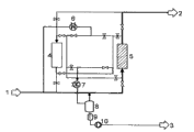
Fig. 1-6 shows an indicative flowchart that changes scheme of the present invention's absorption/regeneration cycle, and wherein the regeneration of absorber is undertaken by recyclegas.The configuration that Fig. 1-6 shows comprises first absorber 4, second absorber 5, compressor 11, heater 6, cooler and condenser 7, phase separator 8, receiver 9, pump 10 and can comprise fresh HCl feeding line 1, HCl discharge line 2 and (chloro) hydrocarbon discharge line 3 by the pipeline of valve opening and closing.Drawn absorber in adsorption operations does not have diagram to be presented at absorber in the regenerative operation.
Fig. 1 illustrates the inventive method step I).First absorber 4 and second absorber 5 are connected in series, therefore fresh hydrogen chloride 1 also no longer adsorb (chloro) hydrocarbon by two absorbers until complete basically load (chloro) hydrocarbon of first absorber 4 in succession, and therefore all phosgene are gone out by the first absorber phase transition and are present in second absorber 5.
The inventive method step I ia that Fig. 2 explanation is regenerated with recyclegas).Fresh hydrogen chloride only passes through second absorber 5, first absorber 4 of regenerating simultaneously now.The hydrogen chloride that is comprising in first absorber 4 also passes through condenser 7 and phase separator 8 by compressor 11 subsequently by heater 6, absorber 4.In this step, the hydrogen chloride materials flow of (chloro) hydrocarbon by heating desorb and absorb from adsorbent bed by the latter.Liquid, (chloro) hydrocarbon of essentially no phosgene in condenser 7 from the hydrogen chloride of load (chloro) hydrocarbon condensation go out and in phase separator 8, from air-flow, isolate and discharge through receiver 9 as materials flow 10.Opposite in the direction that air communication is crossed absorber 4 and the adsorption step.
The inventive method step I ib that Fig. 3 explanation is regenerated with recyclegas).Heater 6 does not move now, makes circulating current no longer heat but now only by chiller/condenser 7 cooling.The gas direction of passing absorber 4 is converse once more and present once more corresponding to the gas direction in the adsorption operations.
Fig. 4 illustrates the inventive method step I ii).Step I is ii) corresponding to step I) (Fig. 1), difference is and step I) compare, absorber 4 and 5 order exchange.Absorber 5 loads are until no longer therefore absorption (chloro) hydrocarbon and total amount phosgene migrate out in the absorber thus basically.Phosgene be present in now in the downstream absorber 4 or when absorber 4 during for regenerative operation (as shown in Figure 3) migrate out 5 to small part from absorber and enter downstream chloration hydro-oxidation process with materials flow 2.
The inventive method step I va that Fig. 5 explanation is regenerated with recyclegas).Step I va) corresponding to step I ia) (Fig. 2), wherein absorber 5 is a regenerative operation now.
The inventive method step I vb that Fig. 6 explanation is regenerated with recyclegas).Step I vb) corresponding to step I ib) (Fig. 3), wherein absorber 5 is a regenerative operation now.Step I vb) finishes circulation.Next procedure is once more corresponding to step I) (Fig. 1).
Fig. 7-12 shows the indicative flowchart of the variation scheme of the present invention's absorption/regeneration cycle, and wherein the regeneration of absorber uses fresh hydrogen chloride gas to carry out.Configuration shown in the figure comprises first absorber 4, second absorber 5, heater 6, cooler and condenser 7, phase separator 8, receiver 9, pump 10 and can comprise fresh HCl feeding line 1, HCl discharge line 2 and (chloro) hydrocarbon discharge line 3 by the pipeline of valve opening and closing.Save compressor 11.
Fig. 7 illustrates that absorber 4 and absorber 5 loads are connected in series corresponding to Fig. 1.
The inventive method step I ia that Fig. 8 explanation is regenerated with live gas).Second absorber 5, first absorber 4 of regenerating are simultaneously only passed through in fresh hydrogen chloride materials flow now.For this reason, son stream is taken out from fresh hydrogen chloride materials flow 1 and by heater 6, absorber 4, condenser 7 and phase separator 8.In this adsorption step, opposite in the direction of gas by absorber 4 and the adsorption step.Son stream also combines with main materials flow subsequently once more by phase separator 8.
The inventive method step I ib that Fig. 9 explanation is regenerated with live gas).Heater 6 does not move, and makes circulating current no longer heat.The gas direction of passing absorber 4 is converse once more and present once more corresponding to the gas direction in the adsorption operations.
Figure 10 illustrates the inventive method step I ii), and substantially corresponding to Fig. 4.With step I) to compare, absorber 4 and 5 order exchange now.
The inventive method step I va that Figure 11 explanation is regenerated with live gas).Step I va) corresponding to step I ia) (Fig. 8), wherein absorber 5 is a regenerative operation now.
The inventive method step I vb that Figure 12 explanation is regenerated with live gas).Step I vb) corresponding to step I ib) (Fig. 9), wherein absorber 5 is a regenerative operation.Step I vb) finishes circulation.Next procedure is once more corresponding to step I) (Fig. 7).
Claims (7)
1. hydrogen chloride and the hydrocarbon of no phosgene or method of chlorohydrocarbon that from the hydrogen chloride materials flow that comprises hydrocarbon or chlorohydrocarbon photoreactive gas, reclaims no hydrocarbon or chlorohydrocarbon, it comprises:
I) in a first step, first absorber and second absorber are connected in series, and make the fresh hydrogen chloride materials flow that comprises phosgene and hydrocarbon or chlorohydrocarbon at first by first absorber, and subsequently by second absorber, until hydrocarbon or chlorohydrocarbon are no longer adsorbed by first absorber basically
Ii) in second step, make fresh hydrogen chloride materials flow by second absorber, first absorber of regenerating simultaneously obtains the hydrocarbon or the chlorohydrocarbon of essentially no phosgene in regeneration,
Iii) in the 3rd step, make fresh hydrogen chloride materials flow at first by second absorber, and first absorber by regeneration subsequently, until hydrocarbon or chlorohydrocarbon basically no longer by the absorption of second absorber,
Iv) in the 4th step, make fresh hydrogen chloride materials flow by first absorber, second absorber of regenerating simultaneously obtains the hydrocarbon or the chlorohydrocarbon of essentially no phosgene, wherein step I in regeneration)-iv) can carry out one or many by adjoining land.
2. according to the method for claim 1, wherein ii) and/or the hydrogen chloride that is included in each absorber is being comprised as recyclegas in the closed-loop path of compressor, heater, condenser and phase separator pass through adsorbent bed in regeneration step, wherein the recycled hydrogen chloride air-flow was heated before it enters adsorbent bed and leave adsorbent bed at it and cool off later on, in condenser and phase separator, reclaim the hydrocarbon or the chlorohydrocarbon liquid of essentially no phosgene.
3. according to the method for claim 2, step I i wherein) or iv) in two subordinate steps, carry out, at first subordinate step I ia) or iva) in described recycled hydrogen chloride air-flow was heated before it enters adsorbent bed and leave adsorbent bed at it and cool off later on, the recycled hydrogen chloride air-flow is only at second subordinate step I ib) or ivb) in cooling, in condenser and phase separator, obtain the hydrocarbon or the chlorohydrocarbon liquid of essentially no phosgene.
4. according to the method for claim 3, wherein in regeneration step ii) and/or iv), the recycled hydrogen chloride air-flow with adsorption step i) or iii) rightabout is by adsorbent bed, the direction of recycled hydrogen chloride air-flow is at subordinate step I ia) and iib) or iva) and ivb) between opposite once more.
5. according to the method for claim 1, wherein in regeneration step ii) and/or iv), sub-flow point to the fresh hydrogen chloride materials flow of major general goes out, heating, by adsorbent bed to be regenerated, and subsequently by condenser and phase separator, reclaim the hydrocarbon or the chlorohydrocarbon liquid of essentially no phosgene, and choose wantonly after the major ingredient stream of this sub-stream and fresh hydrogen chloride combines, subsequently, by other absorbers in adsorption operations.
6. according to the method for claim 5, wherein ii) or iv) in two subordinate steps, carry out suddenly, at first subordinate step I ia) or iva) in, described son stream was heated it enters adsorbent bed before and leave adsorbent bed at it and cool off later on, and described sub stream) or ivb) heat, in condenser and phase separator, obtain the hydrocarbon or the chlorohydrocarbon liquid of essentially no phosgene no longer at second subordinate step I ib.
7. one kind prepares the method for chlorine by the hydrogen chloride that comprises hydrocarbon or chlorohydrocarbon photoreactive gas, and it comprises the steps:
A) will comprise the materials flow of hydrogen chloride, hydrocarbon or chlorohydrocarbon photoreactive gas by purifying to obtain the not having hydrocarbon of phosgene or the feed stream b1 that comprises HCl of chlorohydrocarbon and essentially no hydrocarbon or chlorohydrocarbon according to each method among the claim 1-6;
B) the materials flow b1 and the oxygenic flow b2 that will comprise HCl introduces zoneofoxidation and the hydrogen chloride Catalytic Oxygen changed into chlorine to obtain comprising the product gas flow b3 of chlorine, hydrogen chloride, water, oxygen, carbon dioxide and inert gas;
C) product gas flow b3 is contacted in the equipment of contacting with aqueous hydrochloric acid I and from materials flow b3 part remove water and hydrogen chloride to stay the air-flow c that comprises hydrogen chloride, chlorine, water, oxygen, carbon dioxide and possible inert gas, wherein at least 5% hydrogen chloride that is included among the materials flow b3 is retained among the air-flow c;
D) optional with air-flow c drying to stay the substantially anhydrous air-flow d that comprises hydrogen chloride, chlorine, oxygen, carbon dioxide and possible inert gas;
E) with air-flow d by compression and cooling and partial liquefaction to obtain the materials flow e of partial liquefaction at least;
F) materials flow e gas/liquid is separated with air-flow f1 that obtains comprising chlorine, oxygen, carbon dioxide and possible inert gas and the liquid stream f2 that comprises hydrogen chloride, chlorine, oxygen and carbon dioxide, and optional making to small part air-flow f1 is recycled to step b);
G) by in tower, distilling with the materials flow g2 of liquid stream f2 separation to obtain chlorine materials flow g1 and to form by hydrogen chloride, oxygen and carbon dioxide basically, wherein part hydrogen chloride flow in the tower in the condensation of the top of tower and as anti-stream is counter, therefore obtains the materials flow g2 of chlorine content for<1 weight %.
Applications Claiming Priority (3)
| Application Number | Priority Date | Filing Date | Title |
|---|---|---|---|
| EP06100960.1 | 2006-01-27 | ||
| EP06100960 | 2006-01-27 | ||
| PCT/EP2007/050716 WO2007085627A1 (en) | 2006-01-27 | 2007-01-25 | Process for extracting (chlorinated) hyrocarbon-free hydrogen chloride and phosgene-free (chlorinated) hydrocarbons from a hydrogen chloride stream containing (chlorinated) hydrocarbons and phosgene |
Publications (2)
| Publication Number | Publication Date |
|---|---|
| CN101374589A CN101374589A (en) | 2009-02-25 |
| CN101374589B true CN101374589B (en) | 2011-07-27 |
Family
ID=37888098
Family Applications (1)
| Application Number | Title | Priority Date | Filing Date |
|---|---|---|---|
| CN2007800034773A Active CN101374589B (en) | 2006-01-27 | 2007-01-25 | Process for extracting (chlorinated) hydrocarbon-free hydrogen chloride and phosgene-free (chlorinated) hydrocarbons from a hydrogen chloride stream containing (chlorinated) hydrocarbons and phosgene |
Country Status (9)
| Country | Link |
|---|---|
| US (1) | US7819949B2 (en) |
| EP (1) | EP1981619B1 (en) |
| JP (1) | JP5158719B2 (en) |
| KR (1) | KR101374952B1 (en) |
| CN (1) | CN101374589B (en) |
| AT (1) | ATE477841T1 (en) |
| DE (1) | DE502007004779D1 (en) |
| ES (1) | ES2350799T3 (en) |
| WO (1) | WO2007085627A1 (en) |
Families Citing this family (15)
| Publication number | Priority date | Publication date | Assignee | Title |
|---|---|---|---|---|
| DE102007016973A1 (en) * | 2007-04-10 | 2008-10-16 | Bayer Materialscience Ag | Regenerative adsorption process for removal of organic components from a gas stream |
| DE102007020144A1 (en) * | 2007-04-26 | 2008-10-30 | Bayer Materialscience Ag | Condensation adsorption process for removal of organic components from a gas stream containing hydrogen chloride |
| CN101724435B (en) * | 2008-10-31 | 2014-04-30 | 中国石油化工股份有限公司 | Dechlorination method of oil product or gas |
| CA2832887A1 (en) | 2011-04-11 | 2012-10-18 | ADA-ES, Inc. | Fluidized bed method and system for gas component capture |
| GB201116801D0 (en) | 2011-09-29 | 2011-11-09 | Johnson Matthey Plc | Purification process |
| CN102445051B (en) * | 2011-10-31 | 2013-07-31 | 绍兴市东湖生化有限公司 | Method for preparing liquid hydrogen chloride form hydrogen chloride gas through compression |
| WO2014047354A1 (en) | 2012-09-20 | 2014-03-27 | ADA-ES, Inc. | Method and system to reclaim functional sites on a sorbent contaminated by heat stable salts |
| US9718047B2 (en) * | 2013-10-24 | 2017-08-01 | Uop Llc | Systems and methods for separating chlorine-containing species from aqueous solutions of chlorine-containing species |
| CN103693620A (en) * | 2013-12-18 | 2014-04-02 | 常熟振氟新材料有限公司 | Device for separating and recovering chlorine gas from chlorine gas and hydrogen chloride mixed gas |
| US10252912B2 (en) | 2015-03-12 | 2019-04-09 | Basf Se | Separation of a phosgene- and hydrogen chloride-comprising stream |
| PT3313815T (en) | 2015-06-29 | 2019-10-17 | Covestro Deutschland Ag | Method for providing hydrogen chloride for chemical conversions |
| CN111298603B (en) * | 2020-03-12 | 2022-02-15 | 江苏维尤纳特精细化工有限公司 | Hydrogen chloride detection processing equipment for chlorothalonil production line and processing technology thereof |
| CN112076529A (en) * | 2020-09-24 | 2020-12-15 | 南通星球石墨股份有限公司 | Device and method for removing siloxane in organic silicon byproduct hydrochloric acid |
| CN112742182B (en) * | 2020-12-22 | 2022-11-04 | 南通润中石墨设备有限公司 | Gas-liquid separation system of HCL falling film absorber |
| CN115979777B (en) * | 2023-03-20 | 2023-05-26 | 苏州冠德能源科技有限公司 | System and method for preparing chloro-isotope sample in chlorinated hydrocarbon based on infrared spectrum and detection method |
Citations (3)
| Publication number | Priority date | Publication date | Assignee | Title |
|---|---|---|---|---|
| WO1994016988A1 (en) * | 1993-01-28 | 1994-08-04 | E.I. Du Pont De Nemours And Company | Hydrogen chloride purfication process |
| DE10234908A1 (en) * | 2002-07-31 | 2004-02-19 | Basf Ag | Production of chlorine from a feed gas containing hydrogen chloride and hydrocarbons and/or chlorohydrocarbons comprises removing (chloro)hydrocarbons from the feed gas and oxidizing the hydrogen chloride |
| CN1568219A (en) * | 2001-10-12 | 2005-01-19 | 旭硝子株式会社 | Method for removing halogen series gas |
Family Cites Families (9)
| Publication number | Priority date | Publication date | Assignee | Title |
|---|---|---|---|---|
| GB196258A (en) * | 1922-04-13 | 1924-02-28 | Ver Chemische & Metallurgische | Process for the manufacture and production of chemically pure hydrochloric acid |
| DE3832804A1 (en) * | 1988-09-28 | 1990-03-29 | Hoechst Ag | PROCESS FOR PREPARING AOX-ARMY, CHLORINE-FREE SALT-ACID ACID |
| JPH03265503A (en) * | 1989-07-18 | 1991-11-26 | Mitsui Toatsu Chem Inc | Method for purifying hydrogen chloride and method for regenerating activated carbon |
| JPH10120402A (en) * | 1996-10-18 | 1998-05-12 | Toagosei Co Ltd | Purification of hydrogen chloride gas |
| JP4192354B2 (en) * | 1999-01-22 | 2008-12-10 | 住友化学株式会社 | Chlorine production method |
| DE102005008612A1 (en) * | 2005-02-23 | 2006-08-24 | Basf Ag | Chlorine production from hydrogen chloride, comprises feeding hydrogen chloride containing stream, feeding, cooling and drying product gas stream, liquefacting the gas stream and separating gas/liquid stream and aqueous hydrochloric acid |
| WO2006109416A1 (en) * | 2005-04-05 | 2006-10-19 | Mitsui Chemicals Polyurethanes, Inc. | Apparatus for polyisocyanate production and apparatus for gas treatment |
| JP4553834B2 (en) * | 2005-12-08 | 2010-09-29 | 住友化学株式会社 | Method for purifying hydrogen chloride |
| DE102007020144A1 (en) * | 2007-04-26 | 2008-10-30 | Bayer Materialscience Ag | Condensation adsorption process for removal of organic components from a gas stream containing hydrogen chloride |
-
2007
- 2007-01-25 KR KR1020087018903A patent/KR101374952B1/en active IP Right Grant
- 2007-01-25 US US12/159,797 patent/US7819949B2/en active Active
- 2007-01-25 ES ES07712101T patent/ES2350799T3/en active Active
- 2007-01-25 JP JP2008551785A patent/JP5158719B2/en active Active
- 2007-01-25 WO PCT/EP2007/050716 patent/WO2007085627A1/en active Application Filing
- 2007-01-25 AT AT07712101T patent/ATE477841T1/en active
- 2007-01-25 EP EP07712101A patent/EP1981619B1/en active Active
- 2007-01-25 CN CN2007800034773A patent/CN101374589B/en active Active
- 2007-01-25 DE DE502007004779T patent/DE502007004779D1/en active Active
Patent Citations (3)
| Publication number | Priority date | Publication date | Assignee | Title |
|---|---|---|---|---|
| WO1994016988A1 (en) * | 1993-01-28 | 1994-08-04 | E.I. Du Pont De Nemours And Company | Hydrogen chloride purfication process |
| CN1568219A (en) * | 2001-10-12 | 2005-01-19 | 旭硝子株式会社 | Method for removing halogen series gas |
| DE10234908A1 (en) * | 2002-07-31 | 2004-02-19 | Basf Ag | Production of chlorine from a feed gas containing hydrogen chloride and hydrocarbons and/or chlorohydrocarbons comprises removing (chloro)hydrocarbons from the feed gas and oxidizing the hydrogen chloride |
Also Published As
| Publication number | Publication date |
|---|---|
| JP2009524623A (en) | 2009-07-02 |
| WO2007085627A1 (en) | 2007-08-02 |
| ATE477841T1 (en) | 2010-09-15 |
| KR20080100178A (en) | 2008-11-14 |
| JP5158719B2 (en) | 2013-03-06 |
| US7819949B2 (en) | 2010-10-26 |
| EP1981619B1 (en) | 2010-08-18 |
| ES2350799T3 (en) | 2011-01-27 |
| EP1981619A1 (en) | 2008-10-22 |
| CN101374589A (en) | 2009-02-25 |
| KR101374952B1 (en) | 2014-03-14 |
| DE502007004779D1 (en) | 2010-09-30 |
| US20080295688A1 (en) | 2008-12-04 |
Similar Documents
| Publication | Publication Date | Title |
|---|---|---|
| CN101374589B (en) | Process for extracting (chlorinated) hydrocarbon-free hydrogen chloride and phosgene-free (chlorinated) hydrocarbons from a hydrogen chloride stream containing (chlorinated) hydrocarbons and phosgene | |
| JP4921489B2 (en) | Chlorine production method | |
| CN101128392B (en) | Method for producing chlorine | |
| JP5537415B2 (en) | Condensation-adsorption process for removing organic components from a hydrogen chloride-containing gas stream | |
| JP2010524814A (en) | Adsorption method for removing inorganic components from gas streams containing hydrogen chloride | |
| JP2005538027A (en) | Method for producing fixed bed chlorine by gas phase catalytic oxidation of hydrogen chloride | |
| JP4011139B2 (en) | Method for separating high purity chlorine from chlorine containing feed gas | |
| KR101121389B1 (en) | Method for the production of chlorine | |
| CN101663233A (en) | Heat integration in deacon | |
| JP2010521294A (en) | Method for removing and recycling condensable components from a chlorine-containing gas stream | |
| JP5036862B2 (en) | Regenerative adsorption method for removing organic compounds from gas streams | |
| CN103380078B (en) | From the distillating method of pneumatic separation chlorine comprising oxygen and chlorine | |
| CN103476705A (en) | Use of liquid hydrogen chloride as a refrigerant in methods for producing chlorine | |
| US20120213693A1 (en) | Use of liquid hydrogen chloride as refrigerant in processes for preparing chlorine | |
| US20120213692A1 (en) | Distillation process for separating chlorine from gas streams comprising oxygen and chlorine |
Legal Events
| Date | Code | Title | Description |
|---|---|---|---|
| C06 | Publication | ||
| PB01 | Publication | ||
| C10 | Entry into substantive examination | ||
| SE01 | Entry into force of request for substantive examination | ||
| C14 | Grant of patent or utility model | ||
| GR01 | Patent grant |