CN1013508B - Devices for reducing deflection and stress in turbing diphragms - Google Patents
Devices for reducing deflection and stress in turbing diphragmsInfo
- Publication number
- CN1013508B CN1013508B CN89107702A CN89107702A CN1013508B CN 1013508 B CN1013508 B CN 1013508B CN 89107702 A CN89107702 A CN 89107702A CN 89107702 A CN89107702 A CN 89107702A CN 1013508 B CN1013508 B CN 1013508B
- Authority
- CN
- China
- Prior art keywords
- space
- dividing plate
- pressure
- seal arrangement
- upstream
- Prior art date
- Legal status (The legal status is an assumption and is not a legal conclusion. Google has not performed a legal analysis and makes no representation as to the accuracy of the status listed.)
- Expired
Links
Images


Classifications
-
- F—MECHANICAL ENGINEERING; LIGHTING; HEATING; WEAPONS; BLASTING
- F01—MACHINES OR ENGINES IN GENERAL; ENGINE PLANTS IN GENERAL; STEAM ENGINES
- F01D—NON-POSITIVE DISPLACEMENT MACHINES OR ENGINES, e.g. STEAM TURBINES
- F01D3/00—Machines or engines with axial-thrust balancing effected by working-fluid
-
- F—MECHANICAL ENGINEERING; LIGHTING; HEATING; WEAPONS; BLASTING
- F01—MACHINES OR ENGINES IN GENERAL; ENGINE PLANTS IN GENERAL; STEAM ENGINES
- F01D—NON-POSITIVE DISPLACEMENT MACHINES OR ENGINES, e.g. STEAM TURBINES
- F01D25/00—Component parts, details, or accessories, not provided for in, or of interest apart from, other groups
- F01D25/24—Casings; Casing parts, e.g. diaphragms, casing fastenings
- F01D25/246—Fastening of diaphragms or stator-rings
Landscapes
- Engineering & Computer Science (AREA)
- Mechanical Engineering (AREA)
- General Engineering & Computer Science (AREA)
- Turbine Rotor Nozzle Sealing (AREA)
- Control Of Turbines (AREA)
- Diaphragms For Electromechanical Transducers (AREA)
- Diaphragms And Bellows (AREA)
Abstract
A turbine comprising at least one stage (20) having a diaphragm (1) which is split in two along a diametrical plane and which includes an outer ring (3) and an inner ring (6) interconnected by virtue of (10 and 11) serving to guide the turbine fluid, the downstream face (14) of the outer ring (3) being pressed against a ring (19) of the turbine stator (4), the diaphragm (1) being provided with sealing (17) providing sealing between the outer ring (3) and the stator (4), the turbine being characterized in that the sealing (17) are disposed on the outer edge (15) of the outer ring (3), in that the downstream face (14) of the outer ring (3) is provided with a land (18) at a distance from the outer edge (15) and bearing against the ring (19) of the stator (4), and in that communication (22, 27, 27') are provided for providing communication between the space (25) situated between the land (18) and the sealing (17), and a space downstream from the diaphragm (1) with the pressure in the space being less than the pressure P1 existing over the upstream face (26) of the diaphragm (1).
Description
In a turbine stage, turbine baffle (Fig. 1) can make fluid by complete expansion (tangential turbine) or demi-inflation (reaction turbine) before the impeller, gives rotor with energy transfer in impeller.
Turbine baffle is a critical piece, and it finishes following function:
It is most effectively by the guide vane expansion fluid;
It is supporting seal arrangement on the periphery of impeller and on the wheel hub of rotor;
It keeps the radial position of the relative impeller blade of guide vane under various working conditions; With
It bears the pressure reduction between its upstream face and the downstream face and does not make mechanical part be subjected to bigger distortion and stress.On this problem, obviously the moderate finite deformation that makes progress of turbine shaft will strengthen axial clearance and lose efficient in this level.
The turbine of describing in the B. P. (patent No. 767,730) comprises dividing plate, and this dividing plate is divided into two parts along diametral plane, and it comprises by turbine fluid guiding device interconnective outer shroud of institute and interior ring.The downstream face of outer shroud has a boss, and this boss is pressed on the ring of turbine stator.
This boss has groove, and very near outer rim.
In dividing plate, can there be stress and distortion.
Turbine baffle is generally by distributing blade or distributing dividing plate to constitute (see figure 1).Distribute blade to be used to guide the fluid that passes through betwixt; It is expanded, and between the outer joint of turbine baffle and its center, provide the mechanical connection effect.Distribute dividing plate then to be used to guide the fluid that passes through betwixt and to make its expansion.This distributes dividing plate to link to each other with the support arm (or gap bridge) of upstream side.This support arm is realized mechanical connection between the outer joint of turbine baffle and its center.
Be that the slit of assembling in the required turbine baffle is to produce heavily stressed reason on gap bridge and the blade that is positioned at its adjacent position on the diametral plane.Equally, near the distortion of slit face distortion greater than its vertical symmetry plane.
For stress and the distortion that reduces turbine baffle, can increase the thickness of turbine baffle, also increased the length of the machine that turbine baffle is housed thus.
Thickness for fear of increasing turbine baffle the objective of the invention is to change the distribution of the power on the turbine baffle outer shroud upstream face.
Can realize the invention is characterized in of this purpose:
Be set on the outer rim of outer shroud at turbine baffle and the seal arrangement accepted between the stator of seal arrangement;
The downstream face of above-mentioned outer shroud has apart from its outer rim one segment distance and abuts in supporting surface or " boss " on this ring of stator;
Be provided with the device that guarantees UNICOM between space between boss and seal arrangement and turbine baffle downstream space; The residing pressure in this space is lower than the pressure P that exists on the turbine baffle upstream face
1;
Above-mentioned space is in the downstream pressure P of this grade
2Under (P
2<P
1).Therefore, with the distance of turbine baffle axis greater than with those aspects of the distance of boss on, the power that affacts on this ring increases to some extent.
Act on reducing of the stress on the connection set between turbine baffle center and its joint, the distortion of ring central part reduces in can making, and thus, can reduce axial clearance and increase the efficient of this grade.
In the first embodiment of the present invention, realize that the device of UNICOM is made of the groove by boss, this groove makes space that is positioned between boss and seal arrangement and the downstream pressure P with this grade of turbine baffle
2UNICOM.
In the second embodiment of the present invention, intercommunicating device is a through hole, and this through hole passes the track ring that boss reclines.Thus, be positioned at the downstream pressure P that space between boss and seal arrangement is in the activity level after this grade that has turbine baffle
2Under.
At the of the present invention the 3rd existing Shi Lizhong, the space between boss and seal arrangement is connected to one of turbo machine downstream stage by passage, and obviously the pressure P of this level is less than pressure P
2
In a kind of improvement of the present invention, the outer shroud of turbine baffle has bigger diameter parts.This its outer rim of bigger diameter parts is provided with seal arrangement.The result has increased the power that is applied to this ring upstream portion.
This partly can be placed between the bolt of fastening stator than major diameter.
In of the present invention another improves, be provided with the space that is positioned at the seal arrangement upstream, the sealing device is arranged on the outer rim of turbine baffle outer shroud of prime of one of them.
Explain the present invention below in conjunction with accompanying drawing.
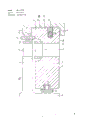
Fig. 1 is the sectional view of first embodiment of the invention.
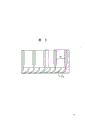
Fig. 2 is the partial side view of first embodiment of the invention turbine baffle.
Fig. 3 is the sectional view of expression gap bridge and blade.
Fig. 4 is the sectional view of second embodiment of the invention.
Fig. 5 is the sectional view of third embodiment of the invention.
Fig. 6 is a kind of improved sectional view of the present invention.
Fig. 7 is another improved sectional view of the present invention.
Fig. 8 is the sectional view of a kind of modification of Fig. 7 device.
Fig. 9 is the sectional view of the another kind of modification of Fig. 7 device.
Now by relevant more detailed explanation the present invention of blade effect who constitutes the driving wheel 2 of rotor 9 parts.Seal arrangement 13 is fixed on the upstream face 14 of turbine baffle 1 around driving wheel 2.
On the outer rim 15 of outer shroud 3, seal arrangement 17 is arranged.The sealing device is contained in the groove 16 and is pressed on the stator inner wall to form sealing.
Annular boss 18 is set on the upstream face 14 of this outer shroud 3 and abuts on the ring 19 that is positioned at the stator 4 around driving wheel 2 and the seal arrangement 13.
Boss 18 is positioned at as close as possible device 13 places.
This boss has groove 22(to see Fig. 2).
The circumference of turbine baffle 1 has two adjacent to the groove 23 of junction plane with at a groove 24 of bottom.
Key is installed in groove 23 in a conventional manner, and these keys are suspended among the stator 4 turbine baffle.
One key also is housed in groove 24 in a conventional manner.This key provide the attached assistant director of a film or play to and key in groove 23 a kind of parts of expanding avoided are provided.
The space 25 that is positioned at 18 of seal arrangement 17 and boss is by the pressure P of groove 22 with the existence of driving wheel 2 downstreams
2Link.
Because the pressure P that the turbine baffle upstream exists
1Greater than pressure P
2So, around the upstream face 26 of apical ring 3, apply power.Therefore, make the stress in the gap bridge 10 of blade 11 and runner 5 reduce about the leverage of boss 18.Equally, be positioned at junction plane and be reduced near the maximum distortion of rotor hub.
In of the present invention a kind of modification as shown in Figure 4, boss 18 no longer includes the groove as Fig. 1 embodiment.But it is provided with the sealing on the outer shroud 19 that leans against stator 4.
In another improvement as shown in Figure 5, boss 18 makes ring 19 sealings equally.The space 25 that seal arrangement 17 and boss are 18 is by passage 27 ' link with one of turbine stage of back.Pressure P is inevitable less than the pressure P of determining in level 20 outlet ports in this grade
2
In the third improvement as shown in Figure 6, the outer rim 29 that seal arrangement 17 is installed on the outer shroud 3 has than major diameter part 28.This partly has to be placed on than major diameter and is used for stator 4 is tightened in thickness between together the bolt.
The space 25 that boss 18 and seal arrangement are 17 is by the downstream space UNICOM that be right after of the groove by boss 18 with level 20.Also can use as shown in Figure 4 linked hole or other any passages to make a space 25 and grade space UNICOM of 20 downstreams existence.The pressure P that its pressure is determined less than driving wheel 2 outlet ports in this space
2
Therefore, the size that does not increase stator just can on the upstream face 26 of outer shroud 3, apply power and this power greater than the power among the embodiment of Fig. 1 and Fig. 4.
Fig. 7 represents the 4th kind of improvement of turbo machine of the present invention.
, the upstream face 26 of turbine baffle 1 has second seal arrangement 31 apart from outer rim 15 1 segment distance places, and the sealing device abuts in the ring 19 that is positioned at prime 20 " driving wheel 2 " stator on every side " on.
The turbine baffle 1 of prime " is similar to dividing plate shown in Figure 4.Annular boss 18 on this dividing plate 1 " has the ring 19 that leans against stator in the mode of sealing " ".Yet it is not with respect to the seal arrangement of outer shroud 3 " outer rim 15 ".Like this, the upstream pressure P that " is in dividing plate 1 " of the space 25 between stator 4 and boss 18 " dividing plate 1 of upstream "
0Under.Space 25 then is in the downstream pressure P of level 20
2Under.
Fig. 8 represents a kind of modification of device shown in Figure 7.In this modification, be positioned at ring 19 on the prime 20 " driving wheel 2 " " narrow and it round with dividing plate 1 " all-in-one-piece ring 33.These ring 33 methods are tied in boss 18 "." mode with sealing abuts on the dividing plate 1 this boss 18.
By ring 33 with the encircle 19 upstream pressure P of " between the passage 34 reserved, be positioned at the dividing plate 1 of seal arrangement 17 and boss 18 " between space 30 remain on prime 20 " "
0Down.
The dividing plate 1 that has stress to improve can be " thinner than the dividing plate 1 that does not have stress to improve.
In another modification of as shown in Figure 9 Fig. 7 device, level 20 is identical with Fig. 7's.
Space 30 by passage 27 " be connected to more prime 20 " ' one of space 30 rather than be connected to and have prime dividing plate 1 " upstream pressure P
0Space 25 ".In the space 25 " ' middle pressure P ' greater than pressure P
0
Like this, the power on the upstream face 26 of dividing plate 1 of being applied to is greater than applied force in Fig. 7 device, and this is because pressure reduction P '-P
2Greater than P
0-P
2
Claims (7)
1, a kind of turbo machine dividing plate stress and texturing device of reducing, its central diaphragm (1) is divided into two parts along diametral plane, and it comprises by turbine fluid guiding device (10 and 11) institute's interconnective outer shroud (3) and interior ring (6), the downstream face (14) of this outer shroud (3) has boss (18), it is pressed on the ring (19) of turbine stator (4), it is characterized in that, described dividing plate (1) has the seal arrangement (17) of realizing sealing between outer shroud (3) and stator (4), described seal arrangement (17) is arranged on the outer rim (15) of outer shroud (3), the boss (18) of downstream face (14) is apart from outer rim (15) one segment distances and abut on the ring (19) of stator (4), be provided with the intercommunicating device (22 of mutual UNICOM between the downstream space of the space (25) realizing being positioned between boss (18) and seal arrangement (17) and dividing plate (1), 27,27 '), the pressure of above-mentioned space (25) is gone up the pressure P that exists less than the upstream face (26) of dividing plate (1)
1
According to the described device of claim 1, it is characterized in that 2, above-mentioned intercommunicating device is by constituting by the set groove (22) of boss (18).
According to the described device of claim 1, it is characterized in that 3, above-mentioned intercommunicating device is made of the through hole (27) of the ring (19) of the stator (4) that is reclined by boss (18).
4, according to the described device of claim 1, it is characterized in that, this intercommunicating device constitutes the pressure P that the pressure P in the level (20 ') exists less than level (20) downstream by the passage (27 ') of UNICOM between the level (20 ') in above-mentioned space (25) and level (20) downstream
2
According to the described device of each claim in the claim 1 to 4, it is characterized in that 5, the outer rim (29) that the outer shroud (3) of dividing plate (1) is provided with seal arrangement (17) has bigger diameter parts (28).
6, according to the described device of each claim in the claim 1 to 4, it is characterized in that, comprise second seal arrangement that is positioned on the upstream face (26) of the dividing plate (1) of outer rim (15) one segment distances of the outer shroud (3) of dividing plate (the 1) (pressure P that 31,18 "), the space (30) that wherein is positioned at this first seal arrangement (17) upstream on the outer rim (15) and dividing plate (1) upstream exist
1Isolate, this space (30) link with one of prime upstream space, and pressure is greater than P in prime
1
7, according to the described device of claim 5, it is characterized in that, comprise second seal arrangement (31 that is positioned on dividing plate (1) upstream face (26) of outer rim (15) one segment distances of the outer shroud (3) of dividing plate (1), 18 "), wherein be positioned at the space (30) of this first seal arrangement (17) upstream on the outer rim (15) and the pressure P of dividing plate (1) upstream existence
1Isolate, this space (30) link with one of prime upstream space, and pressure is greater than pressure P in prime
1
Applications Claiming Priority (2)
| Application Number | Priority Date | Filing Date | Title |
|---|---|---|---|
| FR8813117A FR2637650B1 (en) | 1988-10-06 | 1988-10-06 | DEVICES FOR REDUCING ARROWS AND STRESSES IN TURBINE DIAPHRAGMS |
| FR8813117 | 1988-10-06 |
Publications (2)
| Publication Number | Publication Date |
|---|---|
| CN1042967A CN1042967A (en) | 1990-06-13 |
| CN1013508B true CN1013508B (en) | 1991-08-14 |
Family
ID=9370749
Family Applications (1)
| Application Number | Title | Priority Date | Filing Date |
|---|---|---|---|
| CN89107702A Expired CN1013508B (en) | 1988-10-06 | 1989-10-06 | Devices for reducing deflection and stress in turbing diphragms |
Country Status (12)
| Country | Link |
|---|---|
| US (1) | US5024581A (en) |
| EP (1) | EP0362756B1 (en) |
| JP (1) | JPH02146205A (en) |
| CN (1) | CN1013508B (en) |
| AT (1) | ATE78320T1 (en) |
| CS (1) | CS568089A3 (en) |
| DE (1) | DE68902124T2 (en) |
| ES (1) | ES2034548T3 (en) |
| FR (1) | FR2637650B1 (en) |
| GR (1) | GR3005956T3 (en) |
| MX (1) | MX170952B (en) |
| ZA (1) | ZA897626B (en) |
Families Citing this family (9)
| Publication number | Priority date | Publication date | Assignee | Title |
|---|---|---|---|---|
| US5115642A (en) * | 1991-01-07 | 1992-05-26 | United Technologies Corporation | Gas turbine engine case with intergral shroud support ribs |
| GB0319002D0 (en) * | 2003-05-13 | 2003-09-17 | Alstom Switzerland Ltd | Improvements in or relating to steam turbines |
| US7637081B2 (en) | 2003-08-27 | 2009-12-29 | Niikura Scales Co., Ltd. | Article storage device |
| GB2417298B (en) * | 2004-08-21 | 2008-12-24 | Alstom Technology Ltd | Sealing arrangement |
| ES2285915B1 (en) * | 2005-10-11 | 2008-10-16 | Airbus España, S.L. | SEALING SYSTEM OF VARIABLE SLOTS FOR MACHINES TESTED IN AN AERODYNAMIC TUNNEL. |
| US7758307B2 (en) * | 2007-05-17 | 2010-07-20 | Siemens Energy, Inc. | Wear minimization system for a compressor diaphragm |
| DE102014221152A1 (en) * | 2014-10-17 | 2016-04-21 | Siemens Aktiengesellschaft | Sealing of a sealing cup suspension |
| FR3036435B1 (en) * | 2015-05-22 | 2020-01-24 | Safran Ceramics | TURBINE RING ASSEMBLY |
| RU186946U1 (en) * | 2018-11-08 | 2019-02-11 | Акционерное общество "Уральский турбинный завод" | Device for controlling the flow rate of the working fluid of a heat engine |
Family Cites Families (14)
| Publication number | Priority date | Publication date | Assignee | Title |
|---|---|---|---|---|
| US1154777A (en) * | 1914-02-21 | 1915-09-28 | Gen Electric | Attaching means for nozzles. |
| US1242578A (en) * | 1916-09-05 | 1917-10-09 | Moore Steam Turbine Corp | Steam-turbine. |
| US1352277A (en) * | 1919-01-09 | 1920-09-07 | Gen Electric | Elastic-fluid turbine |
| US1549209A (en) * | 1924-09-18 | 1925-08-11 | Bbc Brown Boveri & Cie | Guide apparatus of steam turbines |
| GB243974A (en) * | 1925-04-20 | 1925-12-10 | Jan Kieswetter | Improvements relating to turbine casings having transverse partitions and the like therein |
| GB374783A (en) * | 1930-12-04 | 1932-06-16 | Bbc Brown Boveri & Cie | Improvements in and relating to steam turbines |
| DE732470C (en) * | 1942-03-15 | 1943-03-03 | Turbinenfabrik Brueckner Kanis | Guide vane mounting for overpressure steam or gas turbines |
| GB597953A (en) * | 1943-05-21 | 1948-02-06 | Rateau Soc | Improvements in gas turbines |
| GB702966A (en) * | 1950-10-25 | 1954-01-27 | British Thomson Houston Co Ltd | Improvements in and relating to elastic fluid pressure turbines |
| GB767730A (en) * | 1954-04-09 | 1957-02-06 | Vickers Electrical Co Ltd | "improvements relating to nozzle diaphragms for elastic fluid turbines" |
| US2905434A (en) * | 1954-07-08 | 1959-09-22 | Westinghouse Electric Corp | Turbine apparatus |
| US3021110A (en) * | 1960-03-01 | 1962-02-13 | Gen Electric | High temperature turbine nozzle retaining means |
| US3169748A (en) * | 1962-12-06 | 1965-02-16 | Westinghouse Electric Corp | Turbine apparatus |
| JPS5313005A (en) * | 1976-07-21 | 1978-02-06 | Hitachi Ltd | Turbine stage internal structure |
-
1988
- 1988-10-06 FR FR8813117A patent/FR2637650B1/en not_active Expired - Lifetime
-
1989
- 1989-10-02 AT AT89118211T patent/ATE78320T1/en not_active IP Right Cessation
- 1989-10-02 ES ES198989118211T patent/ES2034548T3/en not_active Expired - Lifetime
- 1989-10-02 DE DE8989118211T patent/DE68902124T2/en not_active Expired - Lifetime
- 1989-10-02 EP EP89118211A patent/EP0362756B1/en not_active Expired - Lifetime
- 1989-10-02 US US07/415,731 patent/US5024581A/en not_active Expired - Fee Related
- 1989-10-03 MX MX017806A patent/MX170952B/en unknown
- 1989-10-06 CS CS895680A patent/CS568089A3/en unknown
- 1989-10-06 ZA ZA897626A patent/ZA897626B/en unknown
- 1989-10-06 JP JP1262838A patent/JPH02146205A/en active Pending
- 1989-10-06 CN CN89107702A patent/CN1013508B/en not_active Expired
-
1992
- 1992-10-12 GR GR920402279T patent/GR3005956T3/el unknown
Also Published As
| Publication number | Publication date |
|---|---|
| DE68902124D1 (en) | 1992-08-20 |
| CS568089A3 (en) | 1992-10-14 |
| FR2637650A1 (en) | 1990-04-13 |
| JPH02146205A (en) | 1990-06-05 |
| DE68902124T2 (en) | 1992-12-17 |
| ATE78320T1 (en) | 1992-08-15 |
| CN1042967A (en) | 1990-06-13 |
| GR3005956T3 (en) | 1993-06-07 |
| ZA897626B (en) | 1990-07-25 |
| ES2034548T3 (en) | 1993-04-01 |
| US5024581A (en) | 1991-06-18 |
| FR2637650B1 (en) | 1990-11-16 |
| EP0362756B1 (en) | 1992-07-15 |
| MX170952B (en) | 1993-09-22 |
| EP0362756A1 (en) | 1990-04-11 |
Similar Documents
| Publication | Publication Date | Title |
|---|---|---|
| US5848873A (en) | Vacuum pumps | |
| US5445496A (en) | Centifugal compressor with pipe diffuser and collector | |
| CN1013508B (en) | Devices for reducing deflection and stress in turbing diphragms | |
| CN1058774C (en) | Axial-flow blower with guiding in channel | |
| CN1650091A (en) | Device for fixing a rotor on a shaft | |
| CN1485528A (en) | Mixed flow turbine and mixed flow turbine rotor blade | |
| CA2117862A1 (en) | Rotor Blade Damping Structure for Axial-Flow Turbine | |
| US6375413B1 (en) | Vacuum pumps | |
| GB2150638A (en) | Diffuser for a centrifugal compressor | |
| US7390162B2 (en) | Rotary ram compressor | |
| US5860789A (en) | Gas turbine rotor | |
| US5611660A (en) | Compound vacuum pumps | |
| US3957393A (en) | Turbine disk and sideplate construction | |
| HU182853B (en) | Multi-flow gasdynamic pressure-wave turbocompressor | |
| US5257905A (en) | Rotor coupling anti-windage apparatus | |
| CN1195153C (en) | Axial-flow blower | |
| CN1651769A (en) | Delivery system | |
| US20160298457A1 (en) | Rotor damper | |
| CN114673681B (en) | Axial balance and sealing structure of high-speed air suspension fan | |
| CN2223381Y (en) | Steel wire rope nonlinear high-elastic coupling of shaft | |
| CN111379599A (en) | Structure of ship single-stage steam turbine cylinder and steering guide vane ring integrated | |
| US6231287B1 (en) | Rotor windage nut | |
| CN214533202U (en) | Supercharger with two-stage air inlet supercharging | |
| RU2226612C2 (en) | Gas-turbine engine | |
| JP2001248405A (en) | Brush seal and segment for rotary machine such as turbine |
Legal Events
| Date | Code | Title | Description |
|---|---|---|---|
| C10 | Entry into substantive examination | ||
| SE01 | Entry into force of request for substantive examination | ||
| C06 | Publication | ||
| PB01 | Publication | ||
| C13 | Decision | ||
| GR02 | Examined patent application | ||
| C14 | Grant of patent or utility model | ||
| GR01 | Patent grant | ||
| C19 | Lapse of patent right due to non-payment of the annual fee | ||
| CF01 | Termination of patent right due to non-payment of annual fee |