CN1013428B - Method for monitoring and regulating guiding humid medium in offset press - Google Patents
Method for monitoring and regulating guiding humid medium in offset pressInfo
- Publication number
- CN1013428B CN1013428B CN89106800A CN89106800A CN1013428B CN 1013428 B CN1013428 B CN 1013428B CN 89106800 A CN89106800 A CN 89106800A CN 89106800 A CN89106800 A CN 89106800A CN 1013428 B CN1013428 B CN 1013428B
- Authority
- CN
- China
- Prior art keywords
- signal
- paper
- scanning
- seals
- red ink
- Prior art date
- Legal status (The legal status is an assumption and is not a legal conclusion. Google has not performed a legal analysis and makes no representation as to the accuracy of the status listed.)
- Expired
Links
Images


Classifications
-
- B—PERFORMING OPERATIONS; TRANSPORTING
- B41—PRINTING; LINING MACHINES; TYPEWRITERS; STAMPS
- B41F—PRINTING MACHINES OR PRESSES
- B41F33/00—Indicating, counting, warning, control or safety devices
- B41F33/0054—Devices for controlling dampening
Abstract
A method of monitoring dampening-medium feed in an offset printing machine includes scanning non-printed areas in a region of given inked areas by a device of an opto-electric transducer, and evaluating signals generated by the scanning.
Description
The present invention relates to a kind of method that applies wetting agent on the offset press of monitoring.In offset printing process, owe the wet color dot that will cause striped and occur visible uneven distribution at some positions, and if appropriate these positions of words of wetting agent consumption are colourless.This by owing the wet red ink paste used for seals depositional phenomenon that causes, when owing wet beginning, at first betide the higher regional back of red ink paste used for seals cover ratio (by the direction of paper feed).When the degree of owing to wet further improved, the scope of red ink paste used for seals deposition had also enlarged, and so-called " tone " also occur until some positions that do not add printing originally.
The initial stage that tone occurs just could be in sight when observing with magnifying glass.It seldom occurs on the whole width of paper simultaneously.Therefore carry out visual inspection with magnifying glass and just must check comprehensively, for the printer, need expend a large amount of time and need concentrate one's energy whole width.When applying wetting agent when too much,, print off the color and luster contrast property difference of coming and fuzzy though that the degree of safety of tone appears in distance is big.Therefore in order to obtain good printing quality, the direction of effort is to print under the rim condition of tone occurring as much as possible.
Being used for the known method that the amount of wetting agent is monitored and regulated is to determine in the red ink paste used for seals with indirect or direct measuring method on printing machine or the amount of wetting agent on the forme.Yet known method has various shortcomings, therefore in practice through can't stand test.For example, the content infra-red method of the wetting agent in the Hei red ink paste used for seals can not detect.In addition, be subjected to the influence of reflection characteristic on forme surface very big to wet part measurement on the forme face.Therefore the compatibility of the measured value of water layer thickness is different with the difference of forme, in addition, also relevant with the direction of roll printing.
Task of the present invention is will find out a kind of monitoring and/or regulate on the offset press to apply the wetting agent method, and it can determine the situation of owing to wet under the condition that is not subjected to other parameter influences, in order to send indication and/or to regulate.
The feature of method of the present invention is to scan the paper area edge that the is printed on color not red ink paste used for seals paper of stipulating in addition with an optical-electrical converter, and the signal that scanning obtains is judged.Preferably, from the direction of printing, the not red ink paste used for seals paper of its scanning is positioned at the trailing edge in the paper district that is printed on color.In the scope of method of the present invention, also can scan the zone beyond other edges of chromatic zones.
For this reason, the colour examining district on the colour examining band of check printing quality can be advantageously used for the paper district that is printed on color (coloured district) of above-mentioned regulation, this colour examining Qu Shi represents a certain monochrome or a certain printed document.But also can be with the original just a certain suitable surface that red ink paste used for seals is arranged in the image that is printed as coloured district of regulation.Look face in the visual scope that application is printed as is judged.
The paper district that is printed on color of this regulation can be a full tone zone, or has the mesh district (halftoning district) of high surperficial cover ratio, but its look district of a monochrome always, rather than the look district of several color double exposures.Another content of method of the present invention is that it allows with the naked eye to test, and each look face that is scanned is exaggerated and is shown on the screen for this reason.The area that perhaps is scanned only shows on screen.
Another content of method of the present invention is: the signal that the paper of the red ink paste used for seals area edge back of scanning regulation obtains is compared with control value, and according to result relatively send sign institute guiding humid medium not enough owe the signal that wets.Particularly advantageously to this be that this control value occupy between the brightness and the brightness of red ink paste used for seals face of red ink paste used for seals paper not.
Can earlier the signal that obtains be compared with control value, this control value occupy between the brightness of the brightness of red ink paste used for seals paper not and red ink paste used for seals face for this reason.Calculate the share that exceeds or be lower than control value in each area that is scanned then.This area fraction be by the counting of image cell is calculated, be its signal in the described area exceed or the share that is lower than control value be by the counting of image cell is calculated, when described area fraction surpasses the yardstick of regulation, will provide a signal of owing to wet.Signal to the paper scanning gained of the back, red ink paste used for seals district that is positioned at regulation is tried to achieve mean value, with this mean value and a control value relatively, when this mean value surpasses or is lower than this control value, derives one and owes the signal that wets.On the printing machine with a plurality of seal machines, scanning is in the end carried out on a seal machine, and on the printing machine that paper calender and back face printing are arranged, carries out one time complementary scan on the seal machine before the paper wraparound.
This content has been arranged, just may be for applying that wetting agent is monitored automatically and/or regulating automatically.
Scanning can be carried out on the paper that prints, and scanning is to carry out on the paper that prints that also twists on the printing cylinder, in the method for the invention, is not precluded within on the blanket of printing machine or the enterprising line scanning of galley of tensioning.
The method according to this invention, it also can be used to adjustedly except monitoring applies wetting agent, it is characterized in that, and this adjusting is to be judged as foundation with what the signal that scanning obtains did.
The advantageous content of the another one of method of the present invention is: when wet signal occurring owing, the amount that applies wetting agent just improves, and when owing wet signal and no longer occur, applies the just minimizing step by step of amount of wetting agent.
The another one content of method of the present invention is: it scans the red ink paste used for seals surface, and derives a wet part of excessive signal from the signal of scanning gained.For this reason, can cross large-signal and can be used for regulating for wet part that it produced from the red ink paste used for seals surface being scanned the image processing system of signal input that obtains together with owing wet signal to applying wetting agent.
Measure by these subordinates can be carried out favourable improving to the present invention, thereby might be for implementing the arrangement that method proposition of the present invention has advantage.That is, in a probe photoelectric type line scan sensor is housed, this probe can move in the direction perpendicular to printing.Also can be in a probe photoelectric type scanning sensor is housed, the surface that this probe can be positioned to be scanned.Also can be photoelectricity profile scanning sensor is housed in a probe, this probe can move continuously in the direction perpendicular to printing, and when this probe was positioned at the surface that is scanned, the output signal of its face sensor can be used as the foundation of judgement.Can be used for the contrast of setting and actual value from the signal of above-mentioned photoelectric sensor generation.The one scan signal that utilization is produced by photoelectric sensor is determined (predicting) surface and original not edge position between the print surface in regulation.In a probe photoelectric type line scan sensor is housed, the surface that is scanned can be by means of an object lens projection in this sensor, and this line scan sensor is equipped with cylinder lens, and its curved surface is perpendicular to the y direction of this line scan sensor.Below in conjunction with accompanying drawing embodiments of the invention are done detailed explanation.In the accompanying drawings:
Fig. 1 is a part that is printed on the printed sheet of the colour examining band used of check red ink paste used for seals,
Fig. 2 and Fig. 3 are the devices that printed colour examining band is judged in known being used to, and it is equipped with the additional moisture probe that forms one with it,
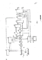
Fig. 4 is applicable to the probe of method of the present invention and for implementing the circuit block diagram of method of the present invention,
Fig. 5 is several time course figure of the signal obtained according to the circuit of Fig. 4,
Fig. 6 is the moisture probe part-structure,
Fig. 7 is an another kind of arrangement of implementing method of the present invention.
Same in the accompanying drawings parts all use same piece number to represent.
Comprise the colour examining band MS that is used to check that contains a plurality of colour examinings district MF in the part of the printed sheet 5 shown in Fig. 1.Among the different colour examining district MF shown in the figure, B is the full tone zone of black, and C is the full tone zone of cyano group cyan, and M is the full tone zone of magenta, and Y is yellow full tone zone, also has the 5th in addition, the 6 two kind of color.In addition, also be shown with among the figure and contain for example the B look of 70~90% cover ratios and the mesh district of C look.When owing wet phenomenon when occurring, at first begin the tone that occurs deceiving in full tone zone B back, its color and luster is darker in illustrated embodiment, and is then more shallow at the color and luster of the back of mesh district B.
In the method for the invention, the scope of scanning be the enclosed with dashed lines among Fig. 1 come that, the capable bar of its scanning paper feed direction when printing is parallel.Use sensor illustrated in fig. 4 to scan.For individual notion is roughly arranged, the capable bar Z of several scannings only is shown in Fig. 1.The scanning of paper feed direction then uses a kind of known devices shown in Fig. 2 and Fig. 3 to carry out during perpendicular to printing.
Except with the line scan sensor, also can use the face scanning sensor, it can scan a face F, and this surface F is equivalent to a colour examining district.
Device shown in Fig. 2 comprises a test desk 1, and a measurement crane span structure 2 is arranged on it, and it is equipped with and measures slide 3, also is useful on 4, one electronic building bricks 6 of four fixture blocks and a personal computer 7 of clamping tested printed sheet 5.One block plate is arranged below the surface layer of test desk 1, so just can utilize the fixture block of magnet and so on that printed sheet 5 is clamped.The personal computer 7 that has display is fixed on the test desk 1 in rotating mode.Measure between slide 3, electronic building brick 6 and the personal computer 7 and link to each other with not shown lead.
This system is grasping the content of colour examining band by some special-purpose data, such as the ordering in each colour examining district, their color, its topped area and mutual spacing etc.Therefore must get on to obtain desired measured value in certain position.
In Fig. 3, crane span structure 2 draws with the ratio of amplifying.It comprises two vertical bogie side frames 11 and 12, and they are supporting other parts on the crane span structure.Crane span structure 2 has two can put the cover cap 13 and 14 that altogether space between the bogie side frame 11,12 is surrounded.These cover caps can be arranged the position shown in Fig. 3, so that and to the inside of measuring crane span structure 2.Bogie side frame 11 and axis of guide 15 of 12 usefulness and the connector 16 that only illustrates partly in the drawings are connected to each other.
Whole measurement slide 3 can move around on the axis of guide 15, and can swing round it.Measuring slide 3 is equipped with the guide pad 17 of two ball jackets by one and is fixed on probe 18 on this guide pad and guiding pressing plate 20 that 19 and two ends are upturned is constituted.In the bottom surface of measuring slide 3 not shown roller is housed.This measurement slide is bearing in above the tested printed sheet 5 during use, thus pop one's head in 18 and 19 and printed sheet 5 in the colour examining band MS distance between each colour examining district MF remain constant.Probe 19 belongs to U.S. Pat-PS4,078,858 disclosed the sort of principle, and it can measure three color channels simultaneously.Probe 18 is used for implementing method of the present invention, is described in detail below in conjunction with Fig. 4.
Toothed timing belt 23 is installed in order to drive measurement slide 3.It is sleeved on two and is bearing on the roller 24 and 25 on bogie side frame 11 and 12 in rotating mode respectively, and guide pad 17 then is fixed in the following back side of this toothed timing belt 23.Left wheel 25 among Fig. 3 is driven by one group of toothed timing belt-deceleration device 26 by a stepper motor 27.24 on another roller is free to rotate, and it is bearing on the take-up device 28.When the cooperation of stepper motor 27 and deceleration device 26 makes the stepper motor revolution move a synchronizing, thereby toothed timing belt 23 and slide 3 will move 0.1 millimeter.
The cover cap 13 of back has a groove-shaped frame 29, has arranged from slide 3 in its inside to be connected to the flat cable that electronic building brick 6 goes.The fast lock dog 30 that holds them in closed condition after cover cap 13 and 14 has been put also is housed on the bogie side frame 11 and 12, stop 31 also is housed in addition, it works altogether with being contained in the steel bar on guide block 17 or the slide 3 or similarly installing (not shown): when make owing to control device is malfunctioning measure that slide has surmounted the minimum range stipulated and in too near two bogie side frames any the time, slide 3 automatically can be stopped.
The compressing member 32 of a U-shaped is housed in front cover 14, on this compressing member, is equipped with 5 equidistantly and indicates illuminating lamp along the length of measuring crane span structure 2.Be contained in these lamps on compressing member 32 top flanges and be by the light source (can not see among Fig. 3) of so-called " line lamp " and the projection camera lens 33b that is contained in the compressing member lower flange and constitute, they form each that be located along the same line and grow five cursors of 20 millimeters approximately on printed sheet 5.The effect of cursor is the below for 18 and 19 motion track that the colour examining band MS on the printed sheet 5 is positioned to pop one's head in exactly.
At last, a shift knob 35 is housed on the end face of front cover 14, it can be used to manually operational measure slide 3 and makes it to move on the colour examining band MS position arbitrarily.
Scan with electric charge coupling (CCD) line scan sensor 41 among the embodiment shown in Figure 4.Before address, also can use the face scanning sensor (being video camera) that receiving tube or semiconductor element are housed to scan.
Line scan sensor has various types, and it contains (for example) 1024 light-sensitive elements, and they a) send output register to because of the electric charge that is subjected to illumination and produces forms pulse H(Fig. 5, sequentially read from this register with the form of commutator pulse T at last.Pulse T and H are directed into time-pulse generator 42.Can obtain one from output 43 and act on the vision signal V that line scanner forms by Luminance Distribution.
Delegation on the face that is scanned on the printed sheet 5 can be projected sensor with object lens 44.So just can scan the part in colour examining district and a part of paper that is positioned at MF back, colour examining district of red ink paste used for seals not.Lighting device 40 provides necessary illumination.
Fig. 5 b illustrates an example from 43 vision signals that obtain.It does not have the result of the delegation of tone corresponding to scanning.When beginning tone to occur, the mesh colour examining district B in Fig. 1 for example, vision signal is disturbed, forms the sort of form shown in dotted line among Fig. 5 b.At t
0To t
1Time period in, vision signal is represented the colour examining district, and at t
1To t
2Time period in then represent the not red ink paste used for seals district that it is adjacent.
Can in all sorts of ways vision signal is judged.Vision signal can be exaggerated the back and directly with the naked eye judge on watch-dog 62.When coming with the method for measuring vision signal judged, multiple available method is arranged also.Lifting a kind of simple especially method is example, and this method is input to a threshold values switch with the time period of interested vision signal via a gating circuit, just provides a corresponding signal when signal is lower than threshold values.Also available more complicated method judges, the finishing with digitized circuit and computer system of application simulation.In layout shown in Figure 4, the numeral that is converted into long number according to the degree of depth of tone is handled by digitized circuit.Further handle and do higher leveled control and then have microprocessor system 56 measuring process.
Because every delegation of scanning comprises the time period t that scans the colour examining district
0To t
1With scanning back, the colour examining district time period t in red ink paste used for seals district not
1To t
2, it to produce two pulse I separately
1And I
2,, for this reason, provide time pulse to counter 45 by time-pulse generator 42 as Fig. 5 c and Fig. 5 d.This counter is resetted it by pulse H when each row beginning.The reading of counter is input to logic circuit 46 and provides pulse I by the corresponding coupling with the single figure place of counter
1And I
2
Enter A/D converter 48 from the vision signal V of line scan sensor 41 outputs 43 outputs via amplifier 47.The vision signal of coming out from A/D converter 48 forms a for example data signal DV of 8 bit wides, and it can further process in digitizer subsequently.Colour examining district MF is carried out partial sweep obtains vision signal DVMF via deriving with door 49, to that part of vision signal DVT of red ink paste used for seals domain scanning gained not then via deriving with door 50.
In circuit 51 and 52 subsequently, the digitized vision signal DVMF and the DVT of the first line scanning gained of each colour examining district MF averaged (signal S by the time
1And S
2).These two mean values are done further average (for example getting its arithmetic mean of instantaneous value) again in circuit 53.Derive a threshold values S thus
3, this threshold values illustrates with chain-dotted line in Fig. 5 b.This threshold values is equivalent to the brightness of colour examining district MF and the mean value of the brightness of the printed sheet 5 of red ink paste used for seals not.Corresponding to the luminance signal S of the printed sheet 5 of red ink paste used for seals not
1Can be the brightness that colour examining district next door does not contain the achromatic region of any tone, though, may occur the mean value of the brightness of that part of paper of tone until the red ink paste used for seals not of being originally that scans.
Threshold values S
3Be admitted to a comparator 54 with digitized vision signal DVT.The output signal of comparator depends in time period t
1To t
2Whether interior vision signal has reduced to threshold values S
3Below.This signal (Fig. 5 e) though can be used as is owed wet signal, as the printing material aspect has mistake just may provide the alarm signal of falseness slightly.Therefore the circuit among Fig. 4 is considered and this, and the comparison signal that makes comparator 54 is a counter 55 blocking-up, and time pulse T is passed to the input CLK of counter.Finish colour examining district MF and after being positioned at thereafter not look domain scanning, the content of counter 55 is taken over by register 57, and at short notice counter 55 is put again at every turn.For this reason, microprocessor system 56 sends the pulse that receives signal to register 57, and by the reset terminal of a delay switch 58 with pulse enter counter 55.
Be lower than threshold values S for vision signal V or DV in each time period
3The counting of time pulse can determine to have the size of the area of tone.This size can require to judge according to reality in microprocessor system 56.For example the area when definite is very little, thinks also not have the tone of diffusion this moment, and then this area size can be used as a kind of yardstick of judging the tone diffusion.According to the information that obtains like this, can control the amount that applies wetting agent by some devices (such as numeric display unit or adjuster) from the output 59,60 of microprocessor system 56.
When the not red ink paste used for seals district of each colour examining district MF and back thereof was scanned, the vision signal that obtains was transported in the memory 61.If tone do not occurring in the red ink paste used for seals district, then microprocessor system 56 can be by a signal S
4The part of reading of memory is started, and the latter reads and is transported to watch-dog 63 with the signal that stores in the memory 61.It is constantly read, to keep continuous demonstration.Watch-dog 63 just can show when just tone occurring in a certain colour examining district and affiliated not red ink paste used for seals district thereof.Therefore, can make watch-dog show that required threshold value setting must be lower, like this, the printer just can learn coloured accessing considers whether need to take measures now.The printer can divert one's attention to note watch-dog 63 in other times.
For controlling automatically to applying wetting agent, a cover program can be set in microprocessor system 56, it can increase wetting agent when tone occurring.Can increase the quantity delivered (according to counter 55 outputs) of wetting agent according to the embodiment of the inventive method once according to the tone depth degree that occurs.Also can the quantity delivered that improves wetting agent later on little by little, step by step with its reduction, occur once more until tone.Exceed the tone limit like this " tentative " and do not have substantial influence for printing quality because method of the present invention can be discerned MIN tone, especially when it when the most responsive zone of tone (the full tone zone of black) appears in scanning.
Add too much in order to make method of the present invention also can discern wetting agent, will represent the signal S of the mean flow rate in a certain colour examining district that is scanned
2Send into microprocessor system.When wet part was excessive, coloring can variation.As long as store the setting in a certain colour examining district in microprocessor system, it just can be discerned this panchromatic district and change because of the wet part of excessive brightness that causes.Its result can be used for wet part automatic control.
Excessive for discerning wet part, also can use a graphic system.Excessive wet part can make painted obvious variation, especially all the more so for full tone zone.Image processing system can be compared scanning result with the perfect image of a width of cloth, that is is to compare (because the influence of printed document surface roughness, it is impossible that cover ratio reaches absolutely) with the surperficial cover ratio of its red ink paste used for seals.Difference between the two be can determine, and demonstration and/or control signal provided by the operation method that stores.Since red ink paste used for seals topped when not good color can obviously shoal, compare with the determination of colority value in different or whole colour examinings district, just can determine whether to exist the excessive phenomenon of the too shallow or wet part of colourity.Wet part is excessive at first to be embodied from the less position of red ink paste used for seals, can not regulate by the position difference because apply wetting agent.Surperficial cover ratio in a certain colour examining district, that is be to apply what a percent opening that yardstick is this district of red ink paste used for seals amount, its data are known for the computer of control red ink paste used for seals.These data will be extracted use when logic is coupled.If it is poor than the topped degree that has than the full tone zone of large opening rate (for example) to have the topped degree of full tone zone of very little percent opening, color is more shallow, then exist herein wet part excessive.
When carrying out the transition to second colour examining district, it also controls moving of probe 19 simultaneously microprocessor system 56(, and is not shown) just provide a pulse I to circuit 51,52 and memory 61
3
Fig. 6 schematically illustrates a probe with line scan sensor 41 by means of object lens 44 scanning samples 5.Also be shown with a lighting device 40 among the figure.In order to obtain the mean value perpendicular to direction of line scan, this line scan sensor 41 is furnished with cylinder lens 65.Can exempt so subsequently at electric integration perpendicular to the direction of line scanning.
In the circuit design of Fig. 4, the judgement of vision signal is to carry out with a special circuit of design for it, parameter when tone does not appear in the red ink paste used for seals district is imported into a microprocessor system at last, is then judged by computer processor fully in the circuit design of Fig. 7 comprehensively.
Scanning to the full tone zone MF edge that is positioned at measurement category G in Fig. 7 is undertaken by a sensor 71.The signal that sensor 71 produces imports the input of microprocessor 73 via an A/D converter 72.Microprocessor 73 is connected with a display unit 74, and links to each other with the controller that applies wetting agent on the printing machine via output 75.
After using the corresponding program of a cover, microprocessor 73 can carry out suitable judgement to digitized vision signal.It also can have each step that is similar among Fig. 4.
Claims (19)
1, a kind of method that applies wetting agent on the offset press of monitoring is characterized in that, scans the paper area edge that the is printed on color not red ink paste used for seals paper of stipulating in addition with an optical-electrical converter, and the signal that scanning obtains is judged.
According to the method for claim 1, it is characterized in that 2, from the direction of printing, the not red ink paste used for seals paper of its scanning is positioned at the trailing edge in the paper district that is printed on color.
According to the method for claim 1, it is characterized in that 3, the paper district that is printed on color of this regulation is full tone zone or the mesh district with high surperficial cover ratio.
According to the method for claim 1 or 2, it is characterized in that 4, the look face of using in the visual scope that is printed as is judged.
According to the method for claim 1 or 2, it is characterized in that 5, the look face that each is scanned is exaggerated and is shown on the screen.
6, according to the method for claim 1, it is characterized in that, the signal that the paper of the red ink paste used for seals area edge back of scanning regulation obtains compared with control value, and according to result relatively send sign institute guiding humid medium not enough owe the signal that wets.
According to the method for claim 6, it is characterized in that 7,, earlier signal compared with control value that this control value occupy between the brightness of the brightness of red ink paste used for seals paper not and red ink paste used for seals face, and calculates the share that exceeds or be lower than control value in each area that is scanned.
8, according to the method for claim 7, it is characterized in that, its signal in the described area exceed or the share that is lower than control value be by the counting of image cell is calculated.
9, according to the method for claim 1, it is characterized in that, the signal of the paper scanning gained of the back, red ink paste used for seals district that is positioned at regulation is tried to achieve its mean value, this mean value and a control value comparison, when this mean value surpasses or is lower than this control value, derive one and owe wet signal.
10, according to the method for claim 1, it is characterized in that, in the enterprising line scanning of the paper that prints.
According to the method for claim 1, it is characterized in that 11, scanning is to carry out on the paper that prints that also twists on the printing cylinder.
According to the method for claim 1, it is characterized in that 12, on the printing machine with a plurality of seal machines, scanning is in the end carried out on a seal machine, and on the printing machine that paper calender and back face printing are arranged, carries out one time complementary scan on the seal machine before the paper wraparound.
13, according to the method for claim 1, it is characterized in that, can be to carry out on the blanket or on the printing surface of tensioning in the scanning on the printing machine.
14, according to the method for claim 1, will carry out the adjusting of guiding humid medium in the method, it is characterized in that, applying wetting agent is to regulate according to the judgement that the signal that obtains from scanning is done.
15, according to the method for claim 1, will apply the adjusting of wetting agent in the method, it is characterized in that, when wet signal occurring owing, the amount that applies wetting agent just improves, and when owing wet signal and no longer occur, applies the just minimizing step by step of amount of wetting agent.
16, according to the method for claim 1, it is characterized in that, be transfused to an image processing system from the red ink paste used for seals surface being scanned the signal that obtains.
17, implement the device of the inventive method that claim 1 puts down in writing, it is characterized in that:
In a probe (19), a photoelectric type line scan sensor (41) is set, and an electronic building brick (6) is controlled this probe (19) like this, be of the motion of its do perpendicular to print direction, like this, the corresponding surface that will scan is to detect in the mode of going, and then, measured value is imported in the calculation element (7).
18, implement the device of the inventive method of claim 1 record, it is characterized in that:
In a probe (19), a photoelectric type surface scan sensor is set, and, an electronic building brick (6) makes probe (19) move continuously perpendicular to print direction, then, when probe (19) navigated on the corresponding surface that is scanned, the output signal of this surface probe just was input in the calculation element at once.
19, implement the device of the inventive method that claim 17 puts down in writing, it is characterized in that:
In a probe (19), a photoelectric type line scan sensor (41) is set, the corresponding like this surface that is scanned can project on the sensor (41) by object lens, and, this line scan sensor (41) is equipped with cylinder lens, and its curved surface is swept the y direction of plugging in sensor perpendicular to this row.
Applications Claiming Priority (2)
| Application Number | Priority Date | Filing Date | Title |
|---|---|---|---|
| DE3830732A DE3830732C2 (en) | 1988-09-09 | 1988-09-09 | Process for dampening solution control in an offset printing machine |
| DEP3830732.4 | 1988-09-09 |
Publications (2)
| Publication Number | Publication Date |
|---|---|
| CN1040952A CN1040952A (en) | 1990-04-04 |
| CN1013428B true CN1013428B (en) | 1991-08-07 |
Family
ID=6362648
Family Applications (1)
| Application Number | Title | Priority Date | Filing Date |
|---|---|---|---|
| CN89106800A Expired CN1013428B (en) | 1988-09-09 | 1989-09-08 | Method for monitoring and regulating guiding humid medium in offset press |
Country Status (7)
| Country | Link |
|---|---|
| US (1) | US5050994A (en) |
| EP (1) | EP0357987B1 (en) |
| JP (1) | JPH02108542A (en) |
| CN (1) | CN1013428B (en) |
| AU (1) | AU617864B2 (en) |
| CA (1) | CA1319294C (en) |
| DE (2) | DE3830732C2 (en) |
Families Citing this family (34)
| Publication number | Priority date | Publication date | Assignee | Title |
|---|---|---|---|---|
| DE4106082A1 (en) * | 1990-04-26 | 1991-10-31 | Heidelberger Druckmasch Ag | METHOD AND DEVICE FOR POSITIONING A SENSOR DEVICE |
| DE4214139C2 (en) * | 1992-04-29 | 2002-01-10 | Heidelberger Druckmasch Ag | Process for dampening solution regulation when printing from a form cylinder in an offset printing machine |
| DE4238557A1 (en) * | 1992-11-14 | 1994-05-19 | Koenig & Bauer Ag | Method for adjusting the amount of dampening solution in an offset rotary printing press |
| US5606913A (en) * | 1993-03-16 | 1997-03-04 | Ward Holding Company | Sheet registration control |
| DE4321177A1 (en) * | 1993-06-25 | 1995-01-05 | Heidelberger Druckmasch Ag | Device for parallel image inspection and color control on a printed product |
| DE4321179A1 (en) * | 1993-06-25 | 1995-01-05 | Heidelberger Druckmasch Ag | Method and device for controlling or regulating the operations of a printing machine |
| US5592880A (en) * | 1993-12-30 | 1997-01-14 | Heidelberger Druckmaschinen | Method of supplying or feeding dampening solution |
| DE4401900C2 (en) * | 1994-01-24 | 1998-07-09 | Heidelberger Druckmasch Ag | Method for controlling a print image position on a sheet in a sheet printing machine |
| DE4402784C2 (en) * | 1994-01-31 | 2001-05-31 | Wifag Maschf | Measuring field group and method for quality data acquisition using the measuring field group |
| DE4402828C2 (en) * | 1994-01-31 | 2001-07-12 | Wifag Maschf | Measuring field group and method for quality data acquisition using the measuring field group |
| DE4413731C2 (en) * | 1994-04-20 | 1998-07-02 | Heidelberger Druckmasch Ag | Process for controlling the temperature of the printing ink in a printing press |
| DE4413736C2 (en) * | 1994-04-20 | 1997-12-18 | Heidelberger Druckmasch Ag | Process for checking the wear of a printing form in a printing press |
| DE4413773C2 (en) * | 1994-04-20 | 1998-07-02 | Heidelberger Druckmasch Ag | Process for checking the imaging of printing forms for a printing press |
| US5816164A (en) * | 1994-04-20 | 1998-10-06 | Heidelberger Druckmaschinen Ag | Method and apparatus for monitoring image formation on a printing form |
| DE4436582C2 (en) * | 1994-10-13 | 1998-07-30 | Heidelberger Druckmasch Ag | Method for controlling an amount of dampening solution for a printing form of a running offset rotary printing press |
| JP2746855B2 (en) * | 1995-04-03 | 1998-05-06 | 株式会社東京機械製作所 | Abnormality detection device in nozzle type dampening device |
| DE19518660C2 (en) * | 1995-05-20 | 1997-10-09 | Koenig & Bauer Albert Ag | Procedure for adjusting the amount of dampening solution |
| DE19546260C1 (en) * | 1995-12-12 | 1996-11-21 | Weitmann & Konrad Fa | Monitoring spray quantity on material conveyor method , e.g. paper path moved towards a moistening position, in graphics industry |
| DE19637234C2 (en) * | 1996-09-13 | 2001-08-02 | Michael F Braun | Procedure for checking the color purity of surfaces |
| US6059705A (en) * | 1997-10-17 | 2000-05-09 | United Container Machinery, Inc. | Method and apparatus for registering processing heads |
| DE10152466B4 (en) | 2000-11-24 | 2015-12-17 | Heidelberger Druckmaschinen Ag | Humidity control taking into account several variables influencing the printing process |
| DE10142636B4 (en) * | 2001-08-31 | 2006-04-20 | Maschinenfabrik Wifag | Method and device for detecting a position of a moving printing material web |
| JP2003334930A (en) * | 2002-05-21 | 2003-11-25 | Dainippon Screen Mfg Co Ltd | Printing press and damping water supply method therein |
| JP4638685B2 (en) | 2003-06-10 | 2011-02-23 | ハイデルベルガー ドルツクマシーネン アクチエンゲゼルシヤフト | Method of metering dampening water during printing on an offset press |
| DE10328705A1 (en) * | 2003-06-26 | 2005-01-27 | Koenig & Bauer Ag | Method of setting amount of fountain solution for ink and fountain solution emulsion in offset printing machine by detecting energy needed to reduce fountain solution |
| US6796227B1 (en) * | 2003-08-18 | 2004-09-28 | Quad Tech | Lithographic press dampening control system |
| US7330164B2 (en) * | 2003-08-25 | 2008-02-12 | Thomson Licensing | Video controlled detector sensitivity |
| DE102004021600A1 (en) * | 2004-05-03 | 2005-12-08 | Gretag-Macbeth Ag | Device for inline monitoring of print quality in sheetfed offset presses |
| GB0417586D0 (en) * | 2004-08-06 | 2004-09-08 | Goss Graphic Systems Ltd | Dampening control for a printing press |
| US20070125246A1 (en) * | 2005-12-05 | 2007-06-07 | Goss International Americas, Inc. | Apparatus and method for controlling delivery of dampener fluid in a printing press |
| EP1932670A1 (en) * | 2006-12-13 | 2008-06-18 | Kba-Giori S.A. | Method for controlling a balance between dampening solution and ink in a wet-offset printing press and system for carrying out the method |
| DE102007008017A1 (en) * | 2007-02-15 | 2008-08-21 | Gretag-Macbeth Ag | Color separation correction methods |
| DE102008001178B4 (en) * | 2008-04-15 | 2011-06-30 | manroland AG, 63075 | Method for operating a printing machine |
| CN106862106B (en) * | 2016-11-10 | 2019-07-30 | 浙江三杰印刷科技有限公司 | The anti-mixed goods devices and methods therefor of gold blocking die-cutting machine |
Family Cites Families (12)
| Publication number | Priority date | Publication date | Assignee | Title |
|---|---|---|---|---|
| DE80046C (en) * | ||||
| US3053181A (en) * | 1958-10-30 | 1962-09-11 | Lithographic Technical Foundat | Method for controlling print quality for lithographic presses |
| US3234871A (en) * | 1963-09-17 | 1966-02-15 | Robert E Ostwald | Automatic liquid control and scanning device for duplicating machines |
| DE2141247A1 (en) * | 1970-08-19 | 1972-03-09 | Harris Intertype Corp., Cleveland, Ohio (V.St A.) | Method and device for scanning the amount of liquid on an object |
| CH607021A5 (en) * | 1975-12-30 | 1978-11-30 | Gretag Ag | |
| JPS605472B2 (en) * | 1976-09-22 | 1985-02-12 | 小森印刷機械株式会社 | Ink density control method and device for lithographic printing press |
| US4289405A (en) * | 1978-10-13 | 1981-09-15 | Tobias Philip E | Color monitoring system for use in creating colored displays |
| DD156239A1 (en) * | 1981-01-07 | 1982-08-11 | Eva Luebbe | METHOD FOR CORRECTING DEVIATIONS FROM INSERTION AND HEATING ON OFFSET PRINTING MACHINES |
| US4580944A (en) * | 1983-05-17 | 1986-04-08 | United Technologies Corporation | Aerodynamic flexible fairing |
| DE3483606D1 (en) * | 1983-12-19 | 1990-12-20 | Gretag Ag | METHOD, DEVICE AND COLOR MEASUREMENT STRIP FOR PRINT QUALITY ASSESSMENT. |
| US4947348A (en) * | 1987-03-25 | 1990-08-07 | Kollmorgen Corporation | Densitometer method and system for identifying and analyzing printed targets |
| US4876457A (en) * | 1988-10-31 | 1989-10-24 | American Telephone And Telegraph Company | Method and apparatus for differentiating a planar textured surface from a surrounding background |
-
1988
- 1988-09-09 DE DE3830732A patent/DE3830732C2/en not_active Expired - Fee Related
-
1989
- 1989-08-10 EP EP89114781A patent/EP0357987B1/en not_active Expired - Lifetime
- 1989-08-10 DE DE58909156T patent/DE58909156D1/en not_active Expired - Fee Related
- 1989-08-11 CA CA000608098A patent/CA1319294C/en not_active Expired - Fee Related
- 1989-09-08 CN CN89106800A patent/CN1013428B/en not_active Expired
- 1989-09-11 JP JP1233088A patent/JPH02108542A/en active Pending
- 1989-09-11 AU AU41266/89A patent/AU617864B2/en not_active Ceased
- 1989-09-11 US US07/405,639 patent/US5050994A/en not_active Expired - Lifetime
Also Published As
| Publication number | Publication date |
|---|---|
| CA1319294C (en) | 1993-06-22 |
| EP0357987B1 (en) | 1995-04-05 |
| JPH02108542A (en) | 1990-04-20 |
| US5050994A (en) | 1991-09-24 |
| CN1040952A (en) | 1990-04-04 |
| DE3830732C2 (en) | 2000-05-25 |
| EP0357987A3 (en) | 1991-02-27 |
| DE3830732A1 (en) | 1990-03-15 |
| AU4126689A (en) | 1990-03-15 |
| AU617864B2 (en) | 1991-12-05 |
| DE58909156D1 (en) | 1995-05-11 |
| EP0357987A2 (en) | 1990-03-14 |
Similar Documents
| Publication | Publication Date | Title |
|---|---|---|
| CN1013428B (en) | Method for monitoring and regulating guiding humid medium in offset press | |
| US5724437A (en) | Device for parallel image inspection and inking control on a printed product | |
| US6119594A (en) | Method for regulating inking during printing operations of a printing press | |
| US4665496A (en) | Process and apparatus for the evaluation of the printing quality of a printed product by an offset printing machine | |
| US5144566A (en) | Method for determining the quality of print using pixel intensity level frequency distributions | |
| US20070201066A1 (en) | Density measurement, colorimetric data, and inspection of printed sheet using contact image sensor | |
| CN110509680A (en) | A kind of printing registration method and system | |
| US7000544B2 (en) | Measurement and regulation of inking in web printing | |
| CN1041563A (en) | The monitoring method and the equipment thereof of offset press multi-color printing device printing quality | |
| JPH11151801A (en) | Color optical sensor and print surface testing device using it | |
| DE3225229A1 (en) | COLOR SCANING SYSTEM FOR THE PRODUCTION OF COLOR SEPARATIONS | |
| US5541734A (en) | System for electronically grading yarn | |
| EP2103924A1 (en) | Optical method and measuring device for a sheet of material containing fibre | |
| JP2780657B2 (en) | Quantitative measurement method for blank paper and printed paper surface | |
| WO2006046249A1 (en) | Density measurement, colorimetric data, and inspection of printed sheet using contact image sensor | |
| JPH02167438A (en) | Method and apparatus for judging surface | |
| DE102004061951B4 (en) | Quality control procedure for surface variable printed matter | |
| US7084981B2 (en) | Method for determining the paper quality for halftone printing | |
| JPS61219648A (en) | Inspecting device for printed matter | |
| JPH06246906A (en) | Inspecting device for printed matter | |
| CN1670514A (en) | Apparatus and method for detecting sheet-like material | |
| Hisey | Single Pixel Colorimetry and Optical Densitometry in Philately | |
| JPH10311756A (en) | Method and apparatus for quantification of color irregularity on plastic mold | |
| JPH06246905A (en) | Inspecting device for printed matter | |
| CN1542682A (en) | Method for measuring print error of paper money sample |
Legal Events
| Date | Code | Title | Description |
|---|---|---|---|
| C10 | Entry into substantive examination | ||
| SE01 | Entry into force of request for substantive examination | ||
| C06 | Publication | ||
| PB01 | Publication | ||
| C13 | Decision | ||
| GR02 | Examined patent application | ||
| C14 | Grant of patent or utility model | ||
| GR01 | Patent grant | ||
| C19 | Lapse of patent right due to non-payment of the annual fee | ||
| CF01 | Termination of patent right due to non-payment of annual fee |