CN101337521A - Container securing device - Google Patents
Container securing device Download PDFInfo
- Publication number
- CN101337521A CN101337521A CNA200810127831XA CN200810127831A CN101337521A CN 101337521 A CN101337521 A CN 101337521A CN A200810127831X A CNA200810127831X A CN A200810127831XA CN 200810127831 A CN200810127831 A CN 200810127831A CN 101337521 A CN101337521 A CN 101337521A
- Authority
- CN
- China
- Prior art keywords
- baffle plate
- resettlement section
- securing device
- container
- hole
- Prior art date
- Legal status (The legal status is an assumption and is not a legal conclusion. Google has not performed a legal analysis and makes no representation as to the accuracy of the status listed.)
- Pending
Links
- 230000035622 drinking Effects 0.000 claims description 51
- 235000013361 beverage Nutrition 0.000 abstract 4
- 238000010586 diagram Methods 0.000 description 6
- 230000000694 effects Effects 0.000 description 4
- 239000000463 material Substances 0.000 description 2
- 238000001574 biopsy Methods 0.000 description 1
- 230000015572 biosynthetic process Effects 0.000 description 1
- 239000012611 container material Substances 0.000 description 1
- 230000006866 deterioration Effects 0.000 description 1
- 238000003780 insertion Methods 0.000 description 1
- 230000037431 insertion Effects 0.000 description 1
- 239000007788 liquid Substances 0.000 description 1
- 239000003550 marker Substances 0.000 description 1
- 238000000034 method Methods 0.000 description 1
- 230000004048 modification Effects 0.000 description 1
- 238000012986 modification Methods 0.000 description 1
- 230000002093 peripheral effect Effects 0.000 description 1
- 210000001364 upper extremity Anatomy 0.000 description 1
Images


Classifications
-
- B—PERFORMING OPERATIONS; TRANSPORTING
- B60—VEHICLES IN GENERAL
- B60N—SEATS SPECIALLY ADAPTED FOR VEHICLES; VEHICLE PASSENGER ACCOMMODATION NOT OTHERWISE PROVIDED FOR
- B60N3/00—Arrangements or adaptations of other passenger fittings, not otherwise provided for
- B60N3/10—Arrangements or adaptations of other passenger fittings, not otherwise provided for of receptacles for food or beverages, e.g. refrigerated
- B60N3/105—Arrangements or adaptations of other passenger fittings, not otherwise provided for of receptacles for food or beverages, e.g. refrigerated for receptables of different size or shape
- B60N3/106—Arrangements or adaptations of other passenger fittings, not otherwise provided for of receptacles for food or beverages, e.g. refrigerated for receptables of different size or shape with adjustable clamping mechanisms
-
- B—PERFORMING OPERATIONS; TRANSPORTING
- B60—VEHICLES IN GENERAL
- B60N—SEATS SPECIALLY ADAPTED FOR VEHICLES; VEHICLE PASSENGER ACCOMMODATION NOT OTHERWISE PROVIDED FOR
- B60N3/00—Arrangements or adaptations of other passenger fittings, not otherwise provided for
- B60N3/10—Arrangements or adaptations of other passenger fittings, not otherwise provided for of receptacles for food or beverages, e.g. refrigerated
- B60N3/101—Arrangements or adaptations of other passenger fittings, not otherwise provided for of receptacles for food or beverages, e.g. refrigerated fixed
-
- Y—GENERAL TAGGING OF NEW TECHNOLOGICAL DEVELOPMENTS; GENERAL TAGGING OF CROSS-SECTIONAL TECHNOLOGIES SPANNING OVER SEVERAL SECTIONS OF THE IPC; TECHNICAL SUBJECTS COVERED BY FORMER USPC CROSS-REFERENCE ART COLLECTIONS [XRACs] AND DIGESTS
- Y10—TECHNICAL SUBJECTS COVERED BY FORMER USPC
- Y10S—TECHNICAL SUBJECTS COVERED BY FORMER USPC CROSS-REFERENCE ART COLLECTIONS [XRACs] AND DIGESTS
- Y10S224/00—Package and article carriers
- Y10S224/926—Vehicle attached carrier for beverage container or bottle
Abstract
The present invention provides a beverage container securing device, by which a diameter compensating member (a flap) can not be fastened at the diameter reducing part of a beverage container. The beverage container securing device (100) includes a housing portion (20), with a cylindrical shape, the top of which is open, which is intended to house a beverage container (103), a flap (40) which is positioned within a hole (21a) that is formed within a surrounding wall (21d) of the housing portion (20), and which is installed as to be capable of moving either into the housing portion (20) from the hole (21a) or out of the housing portion (2) to the hole (21a) , and an impelling component (60), which impels the flap toward the interior direction of the housing portion (20), and movably set the flap (40) with the front end (40a) moving upwards and downwards.
Description
Technical field
The present invention relates to a kind of container securing device with cylindric resettlement section and baffle plate, the upper end open of this cylindric resettlement section, be used to accommodate drinking container, this baffle plate is disposed in this hole movably along the hole that is formed on this resettlement section perisporium, and submerges to this hole in this hole reaches this resettlement section or in this resettlement section.
Background technology
In the past, known have a kind of following container securing device (for example referring to Patent Document 1): shown in Fig. 8 (a), it has resettlement section 2, diameter shim element (baffle plate) 1, spring (not shown) and ratchet device (not shown); This resettlement section 2 is inserted for drinking container 103 and is used; This diameter shim element (baffle plate) 1 is arranged at the recess 2b of the perisporium 2a of this resettlement section 2 rotationally, and makes its leading section 1a be projected into this resettlement section 2 to keep drinking container 103 interiorly; This spring applies power to this diameter shim element 1 to anticlockwise direction; This ratchet device is allowed this diameter shim element 1 clockwise rotation, and every process predetermined angular (for example 20 degree, 40 degree, 60 are spent) rotates anti-clockwise and brakes.
Patent documentation 1: TOHKEMY 2003-237452 communique
About container securing device in the past, shown in Fig. 8 (b), for example when the drinking container 103 that diameter shrinkage part will be arranged from the resettlement section 2 upper end open when insert resettlement section 2, the leading section 1a butt of the bottom 103d of this drinking container 103 and diameter shim element 1, and overcome the application force of spring element (not shown) and diameter shim element 1 is clockwise rotated.When further insertion drinking container 103, diameter shim element 1 is subjected to the application force of spring, thereby, this diameter shrinkage part 103c is pressed to the leading section 1a of diameter shim element 1, and drinking container 103 is remained on (with reference to figure 8 (c)) in the resettlement section 2.
When under the state shown in Fig. 8 (c) with drinking container 103 from the resettlement section 2 when taking out, diameter shim element 1 hangs tag on the bossing 103b of drinking container 103, thereby makes and be not easy drinking container 103 is taken out from resettlement section 2.And, also there are the following problems: diameter shim element 1 because of ratchet structure can't anticlockwise ground rotate angle more than the predetermined angular, because the bossing 103b that the leading section 1a of diameter shim element 1 hangs tag at drinking container 103, when taking out drinking container 103 obstinately, can make this diameter shim element 1, ratchet structure breakage.
Summary of the invention
The present invention be directed to that the problems referred to above make, even its purpose is to provide a kind of drinking container 103 that diameter shrinkage part 103c is arranged, the leading section of baffle plate can not hung tag on the bossing 103b of this drinking container 103 and can takes out the container securing device of drinking container smoothly.
For reaching above-mentioned purpose, the present invention is a kind of container securing device, have resettlement section cylindraceous and baffle plate, the upper end open of this resettlement section, be used to accommodate drinking container, this baffle plate is disposed in this hole movably along the hole that is formed on this resettlement section perisporium, in this hole reaches above-mentioned resettlement section, submerge to above-mentioned hole from above-mentioned resettlement section; It is characterized in that this container securing device has the force application component that above-mentioned baffle plate is given prominence in above-mentioned resettlement section, and above-mentioned baffle plate is provided with swingably in the mode that its leading section moves up and down.
In container securing device of the present invention, baffle plate can not hung tag take out drinking container at the bossing of the side of this drinking container.
For example, when taking out drinking container, baffle plate can be swung along with the fluctuating of the bossing of drinking container and diameter shrinkage part, this baffle plate can not hung tag at the bossing of the side of drinking container drinking container is successfully taken out.
Description of drawings
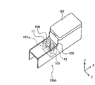
Fig. 1 is the block diagram that the center operations platform in the car of container securing device of embodiment has been used in expression.
Among Fig. 2, (a) be the block diagram of the biopsy cavity marker devices of expression container securing device shown in Figure 1, (b) be the cutaway view of expression container securing device shown in Figure 1.
Fig. 3 is the block diagram of wanting portion of the container securing device shown in presentation graphs 2 (a) or Fig. 2 (b).
Fig. 4 A is the exploded drawings of wanting portion of the container securing device shown in presentation graphs 2 (a) or Fig. 2 (b).
Fig. 4 B is the figure that wants portion of the container securing device shown in presentation graphs 2 (a) or Fig. 2 (b).
Among Fig. 5, (a) being that expression is dissectd the sectional block diagram of the section that obtains to the portion that wants of the container securing device shown in Fig. 2 (a) or Fig. 2 (b) along the A-A line of Fig. 4 B, (b) is to represent the sectional block diagram of the section that obtains is dissectd in the portion that wants of the container securing device shown in Fig. 2 (a) or Fig. 2 (b) along the A-A line of Fig. 4 B.
Fig. 6 is the cutaway view of effect of the container securing device of expression explanation embodiment.
Fig. 7 is the cutaway view of effect of the container securing device of expression explanation embodiment.
Fig. 8 is the cutaway view of the effect of expression explanation container securing device in the past.
Fig. 9 is the block diagram of the baffle plate of expression container securing device shown in Figure 4.
Figure 10 is the cutaway view of the baffle plate of the container securing device shown in the presentation graphs 4A.
Figure 11 is the lateral plan of the baffle plate of the container securing device shown in the presentation graphs 4A.
Figure 12 is the back view of wanting portion of the container securing device shown in the presentation graphs 4B.
The specific embodiment
Below, based on embodiment shown in the drawings the best mode of realizing container securing device of the present invention is described.
Embodiment
At first, the structure to container securing device 100 describes.
As shown in Figure 1, the roughly rectangular-shaped center operations platform (center console) 1000 in the car of embodiment has: the cuboid casing that is formed at its substantial middle portion is a compartment (compartment) 101; Be embedded in a pair of drinking container clamping device 100,100 that the upper opening of this compartment 101 is provided with interiorly; Be arranged at the rear portion of this compartment 101 across step and be rotatably supported in not shown axle and handrail to be opened/closed (armrest) 102 etc.
Container securing device
As shown in Figure 2, container securing device 100 has: be used to accommodate resettlement section 20 drinking container 103 (with reference to figure 7), that be made of the cylindrical shell of upper end open; Be arranged at the panel part 10 on the top of this resettlement section 20; Be arranged at the holding member 200 in the periphery wall 21d outside of this resettlement section 20.
For each member that constitutes this container securing device 100, only otherwise can be because be subjected to from the influence of the heat of drinking container 103 modification taking place, which type of material all can use basically.Preferably can not produce flexible material because of the influence that is subjected to heat.
Panel part
As shown in Figure 1, this flange 11 forms the roughly the same shape of upper opening with the compartment 101 of center operations platform 1000.When with container securing device 100,100 is chimeric when being installed in the compartment 101, the rib 12 of flange 11 connects with the inwall 101a (with reference to figure 1) of compartment 101.
The resettlement section
As shown in Figures 2 and 3, resettlement section 20 is formed with the hole 21a that has run through near the perisporium 21d its upper opening 21b.
Shown in Fig. 2 (b), 20 upper, open end 21c's inner peripheral surface of this resettlement section 20 slowly tilts towards the mode that its diapire 21e narrows down from the resettlement section with its internal diameter.And the following 21f of the diapire 21e of each resettlement section 20 and the bottom wall upper surface of compartment 101 connect, and this container securing device 100 is supported in the compartment 101 (not shown).
Holding member
Guide part
Shown in Fig. 4 A, Fig. 4 B, guide part 30 has E word shape roughly and relative pair of side plates 31A, 31B and with this lower plate 32 that side plate 31A, 31B are linked mutually in its underpart.Each side plate 31A, 31B have supporting top 31Ae, 31Be, form supporting middle part 31Af, 31Bf, supporting bottom 31Ag, the 31Bg of semicircle arcuation roughly and connecting part 31Al, the 31Bl that each part mentioned above is linked; And support between top and the supporting middle part, in the middle part of the supporting and support between the bottom and become groove 31Ac, 31Ad, 31Bc, 31Bd respectively.And side plate 31A, 31B are in the position of the hole 21a that clips perisporium 21d, the lateral surface with perisporium 21d is connected respectively.
Be set at the width dimensions of hole 21a the spacing distance between this side plate 31A, the 31B roughly the same.And upper surface 31Aa, the 31Ba of this side plate 31A, 31B is positioned at the position higher than the upper limb of hole 21a, and lower surface 31Am, the 31Bm of this side plate 31A, 31B is positioned at the position lower than the lower edge of hole 21a.
And, the width dimensions of this hole 21a is set at the width dimensions of baffle plate 40 roughly the same, the height dimension of hole 21a is set at width dimensions greater than baffle plate 40.
Shown in Fig. 4 A, on this supporting middle part 31Af, 31Bf, be formed with axis hole 31Afa, 31Bfa respectively, shown in Fig. 4 B, in this axis hole 31Afa, 31Bfa, be penetrated with spring cotter 70.And the height dimension of the groove 31Ac of guide part 30,31B c and groove 31Ad, 31Bd is set at bigger slightly than the 1st 41 diameter of baffle plate 40 described later and the 2nd 42 diameter respectively.
Baffle plate
Shown in Fig. 9~11, baffle plate 40 has: side-looking is the roughly a pair of plate that is spaced from each other distance 51,52 of C word shape; Through between protrusion 51b, the 52b of between protrusion 51a, the 52a on these plate 51,52 tops and its underpart and be fixed in wherein the 1st 41 and the 2nd 42; The connecting part 53 that the leading section of the leading section of plate 51 and plate 52 is linked.Thereby the circular arc portion on the right side of baffle plate 40 as shown in figure 11 becomes leading section 40a.
With the 1st 41 and the 2nd 42 length settings is the roughly the same size of width W 32 (with reference to Figure 12) with guide part 30.
And as shown in Figure 3, baffle plate 40 extend between side plate 31A, the 31B of the hole 21a of resettlement section 20 and guide part 30, and its leading section 40a is outstanding to the inside of resettlement section 20.
Shown in Fig. 4 B, in groove 31Ac, the 31Bc that extend into guide part 30 for the 1st 41, and can be supported on the upper surface of supporting middle part 31Af, 31Bf movably along this groove 31Ac, 31Bc.And, the 2nd 42 also with the 1st 41 similarly, stretch into groove 31Ad, the 31Bd of high guide part 30, and can along this groove 31Ad, 31Bd be supported on movably supporting bottom 31Ag, 31Bg above.Thereby, make baffle plate 40 to rotate around the 1st 41 or the 2nd 42.
And as shown in Figure 3, this baffle plate 40 is by the fore-and-aft direction of side plate 31A, the 31B of guide part 30 guiding to resettlement section 20, and as shown in Figure 7, and the leading section 40a of baffle plate 40 is outstanding and connect with the side 103a of drinking container 103 to the inside of resettlement section 20.
Coil spring
As Fig. 5 and shown in Figure 6, coil spring 60 is made of linearity two arm 60a, 60b and spiral spring main body 60c.Coil spring main body 60c is installed on spring cotter 70, and, two arm 60a, the 60b of this coil spring 60 extends from spring main body 60c (above-below direction Fig. 5) along linearity roughly, with the 1st 41 and the 2nd 42 connect, to the 1st 41 and the 2nd 42 to the resettlement section 20 side application of forces (left side among Fig. 5).
The Action Specification of container securing device
Below, the effect of container securing device 100 is described.
Accommodating of drink container material
Shown in Fig. 6 (a), when not accommodating drinking container 103, baffle plate 40 is applied power to the inboard of resettlement section 20 by the power that applies of coil spring 60, make its leading section 40a outstanding to the inner space of this resettlement section 20.
Then, when 20 upper opening 21b inserts drinking container 103 from the resettlement section, shown in Fig. 6 (b) and Fig. 7 (a), the bossing 103b of the side face 103a of drinking container 103 and the leading section 40a of baffle plate 40 connect, with the direction pushing of this baffle plate 40 to arrow S1.Therefore, baffle plate 40 overcomes the power that applies of coil spring 60 and is that the center rotates counterclockwise (i.e. swing) with the 1st 41, and is advanced among the hole 21a of perisporium 21d of resettlement section 20.
Since coil spring 60 always to baffle plate 40 to the resettlement section 20 side application of forces, therefore when further with drinking container 103 when insert resettlement section 20, the front end 40a of baffle plate 40 is to the diameter shrinkage part 103c of drinking container 103 moving contact.At this moment, because of 60 pairs of baffle plates 40 of coil spring to the resettlement section 20 side application of forces, so baffle plate 40 is that the center is carried out clockwise direction and rotated (i.e. swing) with the 2nd 42, be pushed out inside (with reference to figure 7 (b)) simultaneously to resettlement section 20.Therefore, the leading section 40a of baffle plate 40 can not be subjected to the protruding 103b of drinking container 103 to hinder ground and its diameter shrinkage part 103c connects, thereby can keep drinking container 103.Therefore, drinking container 103 can be fixed in the resettlement section 20 reliably.
The taking-up of drinking container
When taking out drinking container 103, when drinking container 103 is picked up from resettlement section 20, shown in Fig. 7 (c), the leading section 40a of the baffle plate 40 that connects with its diameter shrinkage part 103c is slided to protruding 103b simultaneously by the S2 direction pushing of the protruding 103b of drinking container 103 along the top.When carrying out this slip, baffle plate 40 overcomes the elastic force of coil spring 60, be that the center rotates counterclockwise (i.e. swing) with the 2nd 42, and the leading section 40a of baffle plate 40 is pushed among the hole 21a of resettlement section 20.
Since baffle plate 40 always by coil spring 60 to the resettlement section 20 side application of forces, therefore when further picking up drinking container 103, the leading section 40a of baffle plate 40 crosses this bossing 103b and to the 103d moving contact of the bottom of drinking container 103.At this moment, this baffle plate 40 is that anticlockwise motion is carried out at the center with the 2nd 42, is urged simultaneously to the inside of resettlement section 20, turns back to the initial condition of not accommodating drinking container 103.
And shown in Fig. 4 B, above-mentioned supporting middle part 31Af, 31Bf form semicircle arcuation roughly, so baffle plate 40 can successfully be swung.
As shown in Figure 7, because baffle plate 40 swings when taking out drinking container 103, therefore can make the diameter shrinkage part 103c that baffle plate 40 can not hang tag at drinking container 103 and successfully take out drinking container 103.Therefore, there is not the damaged possibility of these baffle plate 40 meetings.
Like this, when taking out drinking container 103, baffle plate 40 is along with the fluctuating swing of the diameter shrinkage part 103c of drinking container 103, therefore, can not be subjected to the protruding 103b obstruction of drinking container 103 and keep its diameter shrinkage part 103c reliably, thereby drinking container 103 can be fixed in resettlement section 20 reliably.
Usually will keep the parts of drinking container to be arranged on the inwall of the resettlement section of accommodating drinking container rotationally or be equivalent on the position of this inwall, therefore most cases is outside these holding member integral body are exposed to, when drink liquid is attached to the rotation base portion of this holding member and deterioration, this holding member will be difficult to rotate.And, because outside such holding member is exposed to usually, so in the design (appearance design) of car chamber, we can say and be not very outstanding.
The present invention has also solved these above-mentioned problems in the lump.
More than, utilized accompanying drawing that embodiments of the invention are elaborated, but concrete formation is not limited in these embodiment, even the design-calculated change etc. of the scope of the described invention main idea of every claim that does not break away from claims is arranged, also allow to design change, interpolation etc., and be contained among the present invention.
Claims (3)
1. container securing device, have resettlement section cylindraceous and baffle plate, the upper end open of this resettlement section cylindraceous, be used to accommodate drinking container, this baffle plate is disposed in this hole movably along the hole that is formed on this resettlement section perisporium, in this hole reaches above-mentioned resettlement section, in above-mentioned resettlement section, submerge to this hole, it is characterized in that
Have and make above-mentioned baffle plate side-prominent force application component in above-mentioned resettlement section,
The mode that moves up and down with leading section is provided with above-mentioned baffle plate swingably.
2. container securing device according to claim 1 is characterized in that, the leading section of this baffle plate forms side-looking and is roughly semicircle shape.
3. container securing device according to claim 1 and 2 is characterized in that,
Above-mentioned baffle plate has the 1st, the 2nd of configuration up and down;
Above-mentioned force application component is to the 1st, the 2nd axial resettlement section side application of force;
Above-mentioned baffle plate also can arbitrary swing in the middle of the 1st, the 2nd.
Applications Claiming Priority (2)
| Application Number | Priority Date | Filing Date | Title |
|---|---|---|---|
| JP2007173903 | 2007-07-02 | ||
| JP2007173903A JP5154849B2 (en) | 2007-07-02 | 2007-07-02 | Drink container holding mechanism |
Publications (1)
| Publication Number | Publication Date |
|---|---|
| CN101337521A true CN101337521A (en) | 2009-01-07 |
Family
ID=39790324
Family Applications (1)
| Application Number | Title | Priority Date | Filing Date |
|---|---|---|---|
| CNA200810127831XA Pending CN101337521A (en) | 2007-07-02 | 2008-07-02 | Container securing device |
Country Status (4)
| Country | Link |
|---|---|
| US (1) | US7748679B2 (en) |
| EP (1) | EP2011686B1 (en) |
| JP (1) | JP5154849B2 (en) |
| CN (1) | CN101337521A (en) |
Cited By (1)
| Publication number | Priority date | Publication date | Assignee | Title |
|---|---|---|---|---|
| CN111559297A (en) * | 2019-02-13 | 2020-08-21 | 森六汽车配件株式会社 | Beverage container holding device |
Families Citing this family (9)
| Publication number | Priority date | Publication date | Assignee | Title |
|---|---|---|---|---|
| DE102009017235A1 (en) | 2009-04-09 | 2010-10-14 | Fischer Automotive Systems Gmbh & Co. Kg | Holder for a beverage container, comprises an open top container receptacle in which the beverage container is adjustable from the top, a holding element, a guide, an elastic ring and a housing in which the holding element is implemented |
| JP6338932B2 (en) * | 2014-05-28 | 2018-06-06 | カルソニックカンセイ株式会社 | Cup holder |
| JP2016078585A (en) * | 2014-10-15 | 2016-05-16 | 豊田合成株式会社 | Container holder |
| DE102015002669B4 (en) | 2015-03-02 | 2021-09-30 | Audi Ag | Storage device for arrangement in a motor vehicle |
| US10506890B2 (en) * | 2016-03-11 | 2019-12-17 | Toyoda Gosei Co., Ltd. | Cup holder |
| KR101795284B1 (en) * | 2016-07-04 | 2017-11-07 | 현대자동차주식회사 | Cup holder and manufacturing method thereof |
| JP6321242B2 (en) * | 2017-03-03 | 2018-05-09 | カルソニックカンセイ株式会社 | Cup holder |
| US10086736B1 (en) | 2017-03-28 | 2018-10-02 | Ford Global Technologies, Llc | Cup holder assembly having stabilizers |
| JP7470664B2 (en) | 2021-07-14 | 2024-04-18 | 本田技研工業株式会社 | Container holding structure |
Family Cites Families (15)
| Publication number | Priority date | Publication date | Assignee | Title |
|---|---|---|---|---|
| DE29606583U1 (en) * | 1996-04-11 | 1997-10-09 | Fischer Artur Werke Gmbh | Holder for a beverage container |
| US5782448A (en) * | 1996-07-09 | 1998-07-21 | Ldm Technologies, Inc. | Apparatus for supporting a container |
| JP3706536B2 (en) * | 2000-05-12 | 2005-10-12 | 小島プレス工業株式会社 | Vehicle article holding device |
| DE20108250U1 (en) * | 2001-05-16 | 2002-09-19 | Fischer Artur Werke Gmbh | Cup holder for a tailored bottle |
| DE10161122C2 (en) * | 2001-12-12 | 2003-10-23 | Preh Elektro Feinmechanik | Holder for hollow vessels, in particular for beverage containers |
| DE10206267A1 (en) * | 2002-02-15 | 2003-08-28 | Fischer Automotive Sys Gmbh | Holder for a beverage container |
| DE20219606U1 (en) * | 2002-12-18 | 2004-04-29 | Fischer Automotive Systems Gmbh | Holder for a beverage container |
| US6705580B1 (en) * | 2002-12-20 | 2004-03-16 | Daimlerchrysler Corporation | Cup holder for a motor vehicle |
| JP2005349959A (en) * | 2004-06-10 | 2005-12-22 | Inoac Corp | Container holder |
| JP4275101B2 (en) * | 2004-06-11 | 2009-06-10 | 小島プレス工業株式会社 | Vehicle storage device |
| JP4440714B2 (en) * | 2004-06-17 | 2010-03-24 | 株式会社ニフコ | Container holding unit and cup holder device |
| KR100569342B1 (en) * | 2004-08-16 | 2006-04-07 | 현대자동차주식회사 | Support structure of cup holder for automobile |
| KR100600130B1 (en) * | 2004-08-24 | 2006-07-13 | 현대자동차주식회사 | Cup holder for vehicle |
| KR100600132B1 (en) * | 2004-10-02 | 2006-07-13 | 현대자동차주식회사 | Support structure of cup holder for automobile |
| JP2007084022A (en) * | 2005-09-26 | 2007-04-05 | Toyota Motor Corp | Cup holder for vehicle |
-
2007
- 2007-07-02 JP JP2007173903A patent/JP5154849B2/en not_active Expired - Fee Related
-
2008
- 2008-06-27 EP EP08159156.2A patent/EP2011686B1/en not_active Expired - Fee Related
- 2008-07-01 US US12/216,225 patent/US7748679B2/en not_active Expired - Fee Related
- 2008-07-02 CN CNA200810127831XA patent/CN101337521A/en active Pending
Cited By (2)
| Publication number | Priority date | Publication date | Assignee | Title |
|---|---|---|---|---|
| CN111559297A (en) * | 2019-02-13 | 2020-08-21 | 森六汽车配件株式会社 | Beverage container holding device |
| CN111559297B (en) * | 2019-02-13 | 2023-06-16 | 森六汽车配件株式会社 | Beverage container holding device |
Also Published As
| Publication number | Publication date |
|---|---|
| US20090045309A1 (en) | 2009-02-19 |
| EP2011686A2 (en) | 2009-01-07 |
| JP2009012515A (en) | 2009-01-22 |
| JP5154849B2 (en) | 2013-02-27 |
| US7748679B2 (en) | 2010-07-06 |
| EP2011686A3 (en) | 2012-07-04 |
| EP2011686B1 (en) | 2016-08-24 |
Similar Documents
| Publication | Publication Date | Title |
|---|---|---|
| CN101337521A (en) | Container securing device | |
| JP2006056504A (en) | Beverage container holder for automobile | |
| JP5375932B2 (en) | Beverage container closure | |
| CN107531174B (en) | Container holder | |
| JP2009040196A (en) | Cup holder | |
| JPH10250448A (en) | Unfoldable vessel holder | |
| JP2007145177A (en) | Cup holder | |
| JP2009214595A (en) | Cup holder | |
| JPH08207640A (en) | Cup holder | |
| ES2259431T3 (en) | MIRROR FOR VEHICLE UNDERSTANDING A MIRROR PIVOTING ON TWO PERPENDICULAR AXLES. | |
| JP2007161086A (en) | Cup holder for vehicle | |
| JP5120686B2 (en) | Vehicle holding device for vehicle | |
| JP2005178411A (en) | Structure for drink container holder | |
| KR20150003218U (en) | Device for opening and closing cover of cup holder | |
| KR100543755B1 (en) | Cup Holder For Motors Having The Stopper | |
| KR100336692B1 (en) | Cup holder for automobile | |
| JP2004359083A (en) | Cup holder | |
| JP2004331062A (en) | Cylindrical storage device and lining element equipped with storage device | |
| JP3130245U (en) | Glasses case | |
| KR100369002B1 (en) | Cup holder of an automobile | |
| JP4108594B2 (en) | Drink holder | |
| KR100888173B1 (en) | Assist handle for a car | |
| KR100405891B1 (en) | Cup holder for a motor vehicle | |
| JPH078093U (en) | Console box for vehicles with cup holder mechanism | |
| JP2001322474A (en) | Storage body for vehicle |
Legal Events
| Date | Code | Title | Description |
|---|---|---|---|
| C06 | Publication | ||
| PB01 | Publication | ||
| C10 | Entry into substantive examination | ||
| SE01 | Entry into force of request for substantive examination | ||
| C02 | Deemed withdrawal of patent application after publication (patent law 2001) | ||
| WD01 | Invention patent application deemed withdrawn after publication |
Open date: 20090107 |