CN101281680A - Electric apparatus remote-control device and method based on passive standby - Google Patents
Electric apparatus remote-control device and method based on passive standby Download PDFInfo
- Publication number
- CN101281680A CN101281680A CNA200710065113XA CN200710065113A CN101281680A CN 101281680 A CN101281680 A CN 101281680A CN A200710065113X A CNA200710065113X A CN A200710065113XA CN 200710065113 A CN200710065113 A CN 200710065113A CN 101281680 A CN101281680 A CN 101281680A
- Authority
- CN
- China
- Prior art keywords
- remote
- receiver
- energy
- signal
- electrical equipment
- Prior art date
- Legal status (The legal status is an assumption and is not a legal conclusion. Google has not performed a legal analysis and makes no representation as to the accuracy of the status listed.)
- Granted
Links
Images


Abstract
The invention provides an electrical appliance remote control unit and a method based on the passive standby, wherein the electrical appliance remote control unit and the controlled device are constructed as the remotely controlled appliance. The electrical appliance remote control unit includes a receiver and an emitter; the emitter is used for transmitting the signals burdening certain energy to the receiver; the receiver receives the signals and the signals are converted to the electrical signal and trigger the receiver, and the power supply is used to supply power to the receiver in a certain time, thereby making the remotely controlled appliance in the active standby state in a certain time. When the remotely controlled appliance is in the active standby state, the emitter transmits the corresponding operation signals to the receiver; after the receiver receives the operation signals, the controlled device is started to work; and when the controlled device works normally, the device supplies power to the receiver. By the invention, other electrical appliances do not consume any energy when the whole device does not trigger by the outside energy and the remotely controlled appliance is in the working state.
Description
Technical field
The present invention relates to the electrical equipment field of remote control, particularly a kind of electric apparatus remote-control device and method based on passive standby.
Background technology
At present, the use of electric equipment is frequent day by day and extensively, and the user using electric equipment, during as the TV in the household electrical appliance, electric light etc., all need arrive local manual unlocking, powered-down switch that switch is set, uses extremely inconvenience like this.
Along with development of science and technology, for the convenience on using, on above-mentioned electric equipment, be provided with various idle functions such as teleswitch, WOL (Wake On LAN), time switch, and only need to press telepilot and just can operate and use electric equipment.
In the prior art, telechiric device all adopts active receive mode, and can the signal of its remote control transmitter emission come into force and depend on whether receiver of remote-control sytem is in the wait accepting state.Because receive useful remote signal, receiver need receive signal, amplifies, distant control function is implemented in decoding, pushing executing mechanism.That is, receiver need be in the wait accepting state, and the circuit that is in this state requires the expenditure of energy.Therefore, all there is standby energy consumption without exception in electric equipment in the prior art.
Described standby energy consumption is meant the energy resource consumption of electric equipment when shutting down or not exercising its original function, and the effective energy consumption that in use produces with product is different, and standby energy consumption is a kind of energy dissipation basically.
Be to reduce stand-by power consumption, according on April 4th, 2005 " section's newspaper net ": " it is zero that a kind of standby power control chip of the associate professor Zhou Xianpu of University Of Science and Technology of the Inner Mongol invention makes household electrical appliances energy consumption under holding state.After testing, installing under the family appliance standby state of chip, the static standby current of AC side is zero, and the static standby current of DC side is 0.35 microampere, and the energy consumption of device own only is 3 microwatts.After household electrical appliances started, battery output current detected value wherein was zero.”
Though by adopting above-mentioned technology can reduce the stand-by power consumption of electric equipment,, it can only be low as far as possible adopting the stand-by power consumption of electric equipment of the telechiric device of active receive mode, absolutely not realization zero-power.
In a word, adopt telechiric device of the prior art can bring following defective inevitably: to increase the stand-by power consumption of electric equipment, wasted energy; Make electric equipment be in the standby power consumption state for a long time and shorten its serviceable life greatly; There is potential safety hazard.
Summary of the invention
In view of problems of the prior art, the object of the present invention is to provide a kind of electric apparatus remote-control device and method based on passive standby, make applicable to various electric equipments, to have versatility by the electric equipment no standby power.
The invention provides a kind of electric apparatus remote-control device, this electric apparatus remote-control device and controlled device constitute remote-controlled electrical equipment, and this electric apparatus remote-control device comprises receiver and transmitter; Wherein, this transmitter is used to launch the signal of the certain energy of carrying to receiver; This receiver receives the signal of the certain energy of carrying, this signal is converted into electric signal, and triggers this receiver, makes receiver obtain power supply within a certain period of time, thereby makes remote-controlled electrical equipment be in active holding state in this certain hour; When remote-controlled electrical equipment was in active holding state, this transmitter emission corresponding operation signal was to receiver; After receiver receives this operation signal, start controlled device and start working, and after this controlled device operate as normal, be this receiver power supply.
The present invention also provides a kind of electrical equipment remote control method, and wherein, this electrical equipment remote control method comprises the steps: that the signal of the certain energy of transmitter emission carrying is to receiver; This receiver receives the signal of the certain energy of carrying, is electric signal with this conversion of signals, and triggers receiver, makes power supply be this receiver power supply within a certain period of time, thereby makes remote-controlled electrical equipment be in active holding state within a certain period of time; When this remote-controlled electrical equipment was in active holding state, the emission corresponding operation signal was to receiver in this certain hour; After this receiver receives the corresponding operating signal, start controlled device and start working, after this controlled device operate as normal, begin to be the receiver power supply.
Beneficial effect of the present invention is, has realized zero stand-by power consumption truly, has saved a large amount of electric energy, has improved the security of system index, has prolonged the serviceable life of electrical equipment; Demonstrated fully humanity concept, in zero stand-by power consumption and do not change under the situation of people's use habit and also can implement various remote controls.
Description of drawings
Fig. 1 is the theory diagram of the remote-controlled electrical equipment of the embodiment of the invention;
Fig. 2 is the theory diagram of the receiver of the electric apparatus remote-control device in the embodiment of the invention;
Fig. 3,4 is the circuit diagram of the different connected modes of passive reception transducing circuit in the embodiment of the invention;
Fig. 5 is the hybrid connected structure circuit diagram that passive energy receiving converter adopts the electric bridge form in the embodiment of the invention;
Fig. 6,7,8,9,10 is the circuit diagram of the different connected modes of time-delay power control circuit in the embodiment of the invention;
Figure 11,12,13 is the flow chart of steps of the electrical equipment remote control method of the embodiment of the invention.
Embodiment
The inventor thinks through long-time research: the problem that thoroughly resolve stand-by power consumption should be resolved following problem: have only the zero energy consumption of using passivity standby device just may realize real meaning 1.; 2. will resolve the power consumption problem of improving back used device itself, if though improve back stand-by power consumption elimination, power consumption becomes big when normal the use, and this loses more than gain; 3. the scrap build cost can not be too high, and too high cost is the obstacle of popularizing; 4. want arbitrarily to change people's use habit for a long time, troublesome poeration then people is unwilling to use and also is difficult to popularize.
In order to address the above problem, the invention provides a kind of electric apparatus remote-control device and method of no standby power, describe the present invention with reference to the accompanying drawings in detail.
Embodiment one
The invention provides a kind of electric apparatus remote-control device based on passive standby, as shown in Figure 1, this electric apparatus remote-control device 20 comprises transmitter 105 and receiver 30; This electric apparatus remote-control device 20 constitutes remote-controlled electrical equipment 10 with controlled device 104; Wherein, the electrical appliance that this remote-controlled electrical equipment 10 can be various remote-controlled operations for example is televisor, computing machine, air conditioner or the like, and the present invention is not as limit.
The signal that transmitter 105 is used to launch the certain energy of carrying is to receiver 30, and the signal of the certain energy of carrying of transmitter 105 emissions comprises the signal of the various ways of sound wave, light wave or electromagnetic wave.
When remote-controlled electrical equipment 10 was in active holding state, transmitter 105 emission corresponding operation signal were to receiver 30; After receiver 30 receives this operation signal, start controlled device 104 and start working, and be receiver 30 power supplies after controlled device 104 operate as normal.
On the other hand, when remote-controlled electrical equipment 10 was in running order, when remote-control receiving circuit 103 received the off signal of transmitter 105 emissions, remote-controlled electrical equipment 10 was got back to the passive standby state; When remote-controlled electrical equipment 10 was in active holding state, receiver 30 did not receive the corresponding operation signal of transmitter 105 emissions in described certain hour, and then remote-controlled electrical equipment 10 is got back to the passive standby state.
Here, active holding state is meant that the receiver 30 of electric apparatus remote-control device 20 obtains electric energy, and remote-controlled electrical equipment 10 is in the state of waiting for the operation signal that receives transmitter 105, and this active holding state continues a very short moment usually; The passive standby state is meant the receiver 30 of electric apparatus remote-control device 20 electric energy of not reentrying, and remote-controlled electrical equipment 10 is in waits for that transmitter 105 emissions have the signal of certain energy so that enter the state of active holding state.
See also Fig. 2, Fig. 2 is the theory diagram of receiver of the electric apparatus remote-control device of the embodiment of the invention among Fig. 1.As shown in the figure, receiver 30 also comprises passive reception transducing circuit 101, time-delay power control circuit 102 and remote-control receiving circuit 103.
Passive reception transducing circuit 101 is used to receive the signal of the certain energy of carrying of transmitter 105 emissions, this signal is converted into electric signal after, be sent to time-delay power control circuit 102.
Circuit structure for the passive reception transducing circuit 101 in the present embodiment sees also accompanying drawing 3,4.
As shown in Figure 3, be the circuit diagram of a kind of connected mode of passive reception transducing circuit 101 in the embodiment of the invention.E1 among Fig. 3, HD, L1 are respectively transform light energy device photoelectric cell or infrasil photoelectric cell, sound wave wave energy converter spare piezoelectric patches or ultrasonic receiver spare, electromagnetic wave wave energy converter spare telefault, antenna or lc circuit, this three does not need to use extra loading power and can independently receive extraneous various types of energy, and above-mentioned energy changed into electric energy, can realize multiple connected mode by K switch 1, K2, K3, also illustrate between transmitter 105 and the receiver 30 simultaneously and can pass through multiple wireless mode transmission of power.Among Fig. 3 the effect of diode D be will receive AC signal transform direct current signal, if being direct current signal then can saving rectifying device D of the output of the switching device among Fig. 3.
See also Fig. 4, Fig. 4 is the circuit diagram of the another kind of connected mode of passive reception transducing circuit in the embodiment of the invention.Compare with Fig. 3, two capacitors of C1, C2 and electronic pump have been increased among Fig. 4, when E1, HD, L1 passivity receiving device receive after corresponding signal changes into electric signal, electric charge has been arranged among the C1, the electric charge of C1 is transferred to C2 by electronic pump with electric charge and is progressively accumulated, removing to drive other circuit workings with the electric energy accumulated of storage like this can be more reliable, can also reduce the emissive power of emitter simultaneously, correspondingly can also increase transmission range.
From above passive as can be seen reception transducing circuit 101 can be simple single passive receiving device, also can be formed the circuit that for example passive energy receiving converter and energy treating apparatus combine by a plurality of dissimilar combination of devices; Wherein, passive energy receiving converter can be made of one or more parallel connections in sound wave wave energy converter spare, transform light energy device, the electromagnetic wave wave energy converter spare, shown in Fig. 3,4; Also can constitute by one or more series-parallel connections in sound wave wave energy converter spare, transform light energy device, the electromagnetic wave wave energy converter spare, as shown in Figure 5, wherein photoelectric cell and resistance connect into the electric bridge form, so can eliminate the interference problem of ordinary ray, the signal that needs only emission during use is aimed at a certain photoelectric cell, make the electric bridge out of trim, output terminal can obtain certain signal.To sum up, this passive energy receiving converter is used for not needing to provide under the situation of extra loading power, receive the energy of transmitter 105 emissions, and be electric signal with this energy conversion, even can also be that the device that provides extra loading power can receive the energy and its energy be changed into electric signal is not provided for other, simultaneously can also set up energy treating apparatus, reduce the emissive power of emitter, correspondingly can also increase transmission range in order to increase the benefit.Wherein energy treating apparatus can be made up of rectifier or electric energy accumulator, and the electric energy accumulator can be that any electric charge that gathers arrives the device that discharges electric energy after the certain parameter index; Here, the complicated and simple of the circuit connecting mode of passive reception transducing circuit 101 should be decided according to suitable environment, job requirement, and connected mode and physical circuit have diversity, do not repeat them here.
Time-delay power control circuit 102 is used to receive the electric signal that passive reception transducing circuit 101 sends, trigger time-delay power control circuit 102, within a certain period of time by this time-delay power control circuit 102, power supply provides electric energy to remote-control receiving circuit 103, makes remote-controlled electrical equipment 10 enter active holding state in described certain hour.
For the circuit structure of the time-delay power control circuit 102 in the present embodiment, see also shown in the accompanying drawing 6,7,8,9,10.
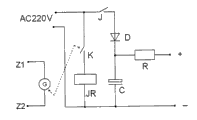
Referring to Fig. 6, a kind of circuit connecting mode for time-delay power control circuit 102, when Z1, Z2 among the figure insert a faint electric signal, the pointer of sensitive galvanometer G deflects and drives the K switch closure, and after the K closure, the power supply of AC220V charges to capacitor C through diode D, and externally power by resistance R, the pointer of G resets to charge and finishes, and after a period of time (being the certain hour that above-mentioned remote-controlled electrical equipment is in active holding state), the capacitor C discharge finishes externally to power to finish thereupon.
See also Fig. 7, another kind of circuit connecting mode for time-delay power control circuit 102, when Z1, Z2 insert a faint electric signal among the figure, the pointer of sensitive galvanometer G deflects and drives the K switch closure, after the K closure, the coil JR of relay gets, the normally opened contact J closure of relay, the power supply of AC220V charges to capacitor C, and externally powers by resistance R through contact J, diode D, after the pointer of G resets, the coil JR dead electricity of relay, normally opened contact J disconnects, and charging finishes, after a period of time, the capacitor C discharge finishes externally power supply end thereupon.
Characteristics for the circuit connecting mode of the time-delay power control circuit 102 among Fig. 6,7 are: the electric signal of reception by electronic switch closes after moment allow a large amount of electric energy of energy storage device savings, power supply is powered to remote-control receiving circuit 103 by this electronic switch simultaneously, this electronic switch disconnected after the electric signal that receives disappeared, and storage device discharges electric energy and works on a period of time by remote-control receiving circuit 103.
Referring to Fig. 8, another kind of circuit connecting mode for time-delay power control circuit 102, when Z1, Z2 insert a faint electric signal among the figure, the pointer of sensitive galvanometer G deflects and drives the K switch closure, after the K closure, the power supply of AC220V charges to capacitor C 1 through K switch, resistance R 2, diode D, and by resistance R 3 triggering one-way SCR BG, the power supply of AC220V externally power supply after current-limiting resistance R1, controllable silicon BG rectification and capacitor C 2 filtering after the controllable silicon BG conducting, after the pointer of G resetted, capacitor C 1 charging finished; Because the effect of C1 accumulate, controllable silicon BG will continue conducting a period of time, when the C1 sparking voltage is lower than the trigger voltage of controllable silicon BG, at controllable silicon BG during in the alternating current zero passage, by externally power supply end thereupon.
Referring to Fig. 9, another kind of circuit connecting mode for time-delay power control circuit 102, when Z1, Z2 insert a faint electric signal among the figure, photoelectric coupled device BG2 work, the power supply of AC220V is through the photoelectric coupled device BG2 of resistance R 2, conducting, to capacitor C 1 charging, and by resistance R 3 triggering one-way SCR BG1, after the controllable silicon BG1 conducting, the power supply of AC220V is externally power supply after current-limiting resistance R1, controllable silicon BG1 rectification and capacitor C 2 filtering, photoelectric coupled device BG2 quits work, and then the C1 charging finishes; Because the effect of C1 accumulate, controllable silicon BG1 will continue conducting a period of time, when the C1 sparking voltage is lower than the trigger voltage of controllable silicon BG1, at controllable silicon BG1 during in the alternating current zero passage, by externally power supply end thereupon.
Wherein, controllable silicon BG can be one-way SCR or bidirectional triode thyristor, specifically adopts which kind of controllable silicon should decide as the case may be when using, and the present invention is not as limit.
Referring to Figure 10, another kind of circuit connecting mode for time-delay power control circuit 102, Z1 in figure, when Z2 inserts a faint electric signal, the pointer of sensitive galvanometer G deflects and drives the K switch closure, after the K closure, the coil JR of relay gets, the normally opened contact JK closure of relay, on the one hand because the effect relay self-locking of JK, the power supply of AC220V is by contact JK on the other hand, through resistance R, capacitor C 1 current limliting, rectifier bridge D rectification, externally power supply after capacitor C 2 filtering is gone up control circuit break-make whether relay TJ from the time and is connected in its load, relay TJ output signal disconnects once its normally closed contact after a period of time, the coil JR dead electricity of relay, the circuit self-locking releasing stops external power supply.
Characteristics for the circuit connecting mode of the time-delay power control circuit 102 among Fig. 8,9,10 are: the electric signal of reception by electronic switch closes after moment energy storage device put aside a spot of electric energy, after the electric signal that receives disappears, stored electric energy allows this electronic switch keep conducting a period of time, and making power supply is that remote-control receiving circuit 103 continues power supply.
From the preferred embodiment of the circuit connecting mode of above several time-delay power control circuits 102 as can be seen, time-delay power control circuit 102 is characterised in that, can trigger this circuit working also within a certain period of time to remote-control receiving circuit 103 power supplies with a faint electric signal, this time-delay power control circuit 102 does not consume any energy after remote-controlled electrical equipment 10 enters normal operating condition; This time-delay power control circuit 102 can be the independent electronic switching circuit of delaying time, also can constitute by electronic switch and energy storage device, wherein electronic switch can be any by voltage or current control circuit break-make semiconductor devices or electromagnetism, mechanical array configuration device in any by voltage or current drives and (for example: one or more formations in the device highly sensitive gauge outfit) supervene displacement.Energy storage device, connect this electronic switch, the electric signal that receives by electronic switch closes after moment allow a large amount of electric energy of energy storage device savings, power supply is powered to remote-control receiving circuit 103 by this electronic switch simultaneously, this electronic switch disconnected after the electric signal that receives disappeared, and stored electric energy works on by remote-control receiving circuit 103; Or, the electric signal of reception by electronic switch closes after moment allow energy storage device put aside a spot of electric energy, after the electric signal of reception disappeared, stored electric energy allowed this electronic switch keep conducting state, making power supply is that remote-control receiving circuit 103 continues power supply.
In the present invention, remote-control receiving circuit 103 can be any receiving circuit that receives the remote signal of transmitter 105 emissions, and its circuit structure and principle of work are known for those skilled in the art, so do not repeat them here.
When remote-control receiving circuit 103 was in described active holding state at remote-controlled electrical equipment 10, remote-control receiving circuit 103 received the straighforward operation signal of transmitters 105 emissions, so that controlled device 104 is realized corresponding straighforward operation.
Remote-control receiving circuit 103 links to each other with controlled device 104, is used for when above-mentioned active holding state, and the electric energy that provides of controlled devices 104 is provided remote-control receiving circuit 103; On the other hand, by remote-control receiving circuit 103, realize the various distant control functions operations of 105 pairs of controlled devices of transmitter, 104 enforcements.
In sum, the start-up course of remote-controlled electrical equipment 10 and when being in normal operating conditions provides required electric energy by time-delay power control circuit 102 and controlled device 104 to remote-control receiving circuit 103 by external power source respectively.
In addition, for receiver 30, the device that it is included, as passive reception transducing circuit 101, time-delay power control circuit 102 and remote-control receiving circuit 103, can adopt above-mentioned different circuit connecting mode respectively, and receiver 30 can be the combination in any that adopts each device of various different circuit connecting modes, and this present invention is described in detail no longer one by one.
Embodiment two
The present invention also provides a kind of electrical equipment remote control method, sees also Fig. 1,2,11,12,13, and how the electric apparatus remote-control device among the embodiment one 20 is realized that electrical equipment remote control method of the present invention is described in detail.
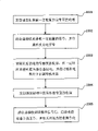
See also Figure 11, this electrical equipment remote control method comprises the steps: the Z1 of passive reception transducing circuit 101, Z2 contact are connected with Z1, the Z2 contact of time-delay power control circuit 102, the AC220V end of time-delay power supply control 1 system circuit 102 is electrically connected with the city, the power output end of time-delay power control circuit 102 is connected with remote-control receiving circuit 103 power access ends, and the power access end of remote-control receiving circuit 103 is connected with the corresponding power supply of the controlled device 104 of remote-controlled electrical equipment 10.After more than connection was finished, the signal of the certain energy of transmitter 105 emission carryings was to receiver 30 (seeing step 1001); This receiver 30 receives this and carries the signal of certain energy, is electric signal (seeing step 1002) with this conversion of signals; Electric signal after this conversion triggers receiver 30, and making power supply within a certain period of time is described receiver 30 power supplies, thereby makes remote-controlled electrical equipment 10 be in active holding state (seeing step 1003) in this certain hour; When remote-controlled electrical equipment 10 was in active holding state, transmitter 105 emission corresponding operation signal were to described receiver 30 (seeing step 1004) in this certain hour; After receiver 30 receives this operation signal, start controlled device 104 and start working, after these controlled device 104 operate as normal, be receiver 30 power supplies (seeing step 1005).
For this electrical equipment remote control method, also have following two kinds of situations and take place:
See shown in Figure 12ly, after remote-controlled electrical equipment 10 is in active holding state (seeing step 1003), in above-mentioned certain hour, receiver 30 does not receive corresponding operation signal, and then remote-controlled electrical equipment 10 is converted to passive standby state (seeing step 1006).
See shown in Figure 13ly, when remote-controlled electrical equipment 10 is in running order (seeing step 1007), when remote-control receiving circuit 103 receives the off signal of transmitter 105 emissions (seeing step 1008), remote-controlled electrical equipment 10 is converted to passive standby state (seeing step 1009).
Electric apparatus remote-control device provided by the invention both can be used as independent device and has been plugged on the various electric equipments and uses, can also be as the part of electric equipment.For example, below will be that air conditioner is that example describes with the electric equipment, electric apparatus remote-control device provided by the invention can be installed on the air conditioner, the receiver that is electric apparatus remote-control device of the present invention is connected with air conditioner, utilize hand-held remote control transmitter to carry out straighforward operation: at first, remote control transmitter to signal that has energy of air conditioner emission, triggers the receiver on the air conditioner by the button on the transmitter, within a certain period of time, air conditioner is in active holding state; When receiver is received the associative operation signal of remote control transmitter emission, just started air conditioner and begin operate as normal, and to the receiver power supply, air conditioner entered normal operating conditions this moment; Here, the associative operation signal is meant that remote control transmitter passes through various function buttons, and for example adjustment, mode of operation are regulated button and waited the coherent signal of launching to receiver, realize the various functions of air conditioner.
If in this air conditioner is in the certain hour of active holding state, receiver does not receive any operation signal by remote control transmitter emission, signal such as adjustment, mode of operation adjusting for example, and then air conditioner is got back to the passive standby state; On the other hand, when air conditioner is in normal operating conditions, can send an off signal to receiver by pressing the shutdown button of remote control transmitter, then stop to the receiver power supply, air conditioner is got back to the passive standby state.
In sum, by electric apparatus remote-control device provided by the invention and method, adopt wireless mode emission certain energy, receiver adopts does not need to provide the energy receiving trap of additional power supply to accept its energy, and utilize circuit working of activated with energy of being accepted that controlled device is normally started, the normal startup of remote-controlled electrical equipment can be passed through remote control transmitter (transmitter) enforcement remote control adjustment after entering duty, except that the remote-control receiving circuit of necessity when the remote-controlled electrical work the power consumption, whole device other electronic installation when not triggered by the corresponding energy in the external world and when remote-controlled electrical equipment enters normal operating conditions does not consume any energy, this invention makes remote-controlled electrical equipment safer when the standby by secondary stepping standby, with the most succinct circuit, minimum cost has solved a global problem, realized the termination target of remote-controlled electric appliance standby zero-power, appeared scientific value suddenly, revolutionary meaning has been arranged.
Above embodiment only is used to illustrate the present invention, but not is used to limit the present invention.
Claims (10)
1. electric apparatus remote-control device, described electric apparatus remote-control device (20) constitutes remote-controlled electrical equipment (10) with controlled device (104), it is characterized in that described electric apparatus remote-control device (20) comprises receiver (30) and transmitter (105); Wherein,
Described transmitter (105) is used to launch the signal of the certain energy of carrying to described receiver (30);
Described receiver (30), receive the signal of the certain energy of described carrying, described signal is converted into electric signal, and trigger described receiver (30), make described receiver (30) obtain power supply within a certain period of time, thereby in described certain hour, make described remote-controlled electrical equipment (10) be in active holding state;
When described remote-controlled electrical equipment (10) when being in active holding state, described transmitter (105) emission corresponding operation signal is to described receiver (30); After described receiver (30) receives described operation signal, start described controlled device (104) and start working, and be described receiver (30) power supply after described controlled device (104) operate as normal.
2. electric apparatus remote-control device according to claim 1 is characterized in that, described receiver (30) comprises passive reception transducing circuit (101), time-delay power control circuit (102) and remote-control receiving circuit (103); Wherein,
Described passive reception transducing circuit (101) is used to receive the signal of the certain energy of described carrying of transmitter (105) emission, is sent to time-delay power control circuit (102) after described signal is converted into electric signal;
Described time-delay power control circuit (102), be used to receive described electric signal, trigger described time-delay power control circuit (102), make described power supply provide electric energy to described remote-control receiving circuit (103) within a certain period of time, in described certain hour, make remote-controlled electrical equipment (10) enter active holding state;
Described remote-control receiving circuit (103), when remote-controlled electrical equipment (10) is in described active holding state, described remote-control receiving circuit (103) receives the straighforward operation signal of described transmitter (105) emission, and controlled device (104) is realized corresponding straighforward operation;
After described controlled device (104) operate as normal, described controlled device (104) is described remote-control receiving circuit (103) power supply.
3. electric apparatus remote-control device according to claim 1 is characterized in that, also comprises:
When described remote-controlled electrical equipment (10) was in running order, when described remote-control receiving circuit (103) received the off signal of transmitter (105) emission, described remote-controlled electrical equipment (10) was got back to the passive standby state;
When described remote-controlled electrical equipment (10) was in described active holding state, described receiver (30) did not receive transmitter (105) emission corresponding operation signal in described certain hour, and then described remote-controlled electrical equipment (10) is got back to the passive standby state.
4. electric apparatus remote-control device according to claim 2 is characterized in that, described passive reception transducing circuit (101) is passive energy receiving converter, wherein,
Described passive energy receiving converter is made of in sound wave wave energy converter spare, transform light energy device, the electromagnetic wave wave energy converter spare one or more.
5. electric apparatus remote-control device according to claim 4 is characterized in that, described passive reception transducing circuit (101) also comprises energy treating apparatus, wherein,
Described energy treating apparatus connects described passive energy receiving converter, is used for described electric signal is carried out signal rectification or charge storage.
6. electric apparatus remote-control device according to claim 2 is characterized in that, described time-delay power control circuit (102) comprises electronic switch and energy storage device; Wherein,
Described electronic switch is used for behind the electric signal that receives described passive reception transducing circuit (101), and turn-on power is to described energy storage device and remote-control receiving circuit (103) power supply;
Described energy storage device connects described electronic switch, is used to store and discharge the electric energy that described power supply provides, and determines the length of described power supply to remote-control receiving circuit (103) power-on time.
7. electric apparatus remote-control device according to claim 1 is characterized in that, the signal type of the certain energy of carrying of described transmitter (105) emission comprises one or more in sound wave, light wave and the electromagnetic wave.
8. electric apparatus remote-control device according to claim 1 is characterized in that, described transmitter (105) is made of other radiating circuit of one or more transmit power levels.
9. an electrical equipment remote control method is characterized in that, described electrical equipment remote control method comprises the steps:
The signal of the certain energy of transmitter emission carrying is to receiver;
Described receiver receives the signal of the certain energy of described carrying, with described conversion of signals is electric signal, and trigger described receiver, making power supply within a certain period of time is described receiver power supply, thereby makes remote-controlled electrical equipment be in active holding state in described certain hour;
When described remote-controlled electrical equipment was in active holding state, described transmitter emission corresponding operation signal was to described receiver in described certain hour;
After described receiver receives described operation signal, start controlled device and start working, after described controlled device operate as normal, begin to be described receiver power supply.
10. electrical equipment remote control method according to claim 9 is characterized in that, also comprises step:
When described remote-controlled electrical equipment was in described active holding state, in described certain hour, described receiver did not receive the corresponding operation signal of transmitter emission, and described remote-controlled electrical equipment is got back to the passive standby state;
When described remote-controlled electrical equipment was in running order, when described receiver received the off signal of transmitter emission, described remote-controlled electrical equipment was got back to the passive standby state.
Priority Applications (1)
| Application Number | Priority Date | Filing Date | Title |
|---|---|---|---|
| CN 200710065113 CN101281680B (en) | 2007-04-04 | 2007-04-04 | Electric apparatus remote-control device and method based on passive standby |
Applications Claiming Priority (1)
| Application Number | Priority Date | Filing Date | Title |
|---|---|---|---|
| CN 200710065113 CN101281680B (en) | 2007-04-04 | 2007-04-04 | Electric apparatus remote-control device and method based on passive standby |
Publications (2)
| Publication Number | Publication Date |
|---|---|
| CN101281680A true CN101281680A (en) | 2008-10-08 |
| CN101281680B CN101281680B (en) | 2012-12-05 |
Family
ID=40014121
Family Applications (1)
| Application Number | Title | Priority Date | Filing Date |
|---|---|---|---|
| CN 200710065113 Active CN101281680B (en) | 2007-04-04 | 2007-04-04 | Electric apparatus remote-control device and method based on passive standby |
Country Status (1)
| Country | Link |
|---|---|
| CN (1) | CN101281680B (en) |
Cited By (10)
| Publication number | Priority date | Publication date | Assignee | Title |
|---|---|---|---|---|
| CN101789635A (en) * | 2010-01-22 | 2010-07-28 | 李畅 | Zero-power consumption safe standby power supply control device based on infrared remote control |
| CN103888697A (en) * | 2014-02-28 | 2014-06-25 | 刘举柱 | Solid-state relay for achieving standby zero power consumption of television |
| CN106991802A (en) * | 2016-01-21 | 2017-07-28 | 神州龙芯(江苏)智能科技有限公司 | The energy-conservation remote control thereof and system of a kind of electrical equipment |
| CN109391136A (en) * | 2017-08-02 | 2019-02-26 | 郑州宇通客车股份有限公司 | A kind of DC/DC converter wakes up system, vehicle low-voltage power supply system and vehicle |
| CN110956796A (en) * | 2019-12-30 | 2020-04-03 | 广东工业大学 | Wireless switch device, equipment system and power supply on-off operation control method |
| CN111091698A (en) * | 2019-12-30 | 2020-05-01 | 广东工业大学 | Wireless control system and wireless control method for realizing power supply on-off operation of equipment |
| CN111105608A (en) * | 2019-12-30 | 2020-05-05 | 广东工业大学 | Wireless control system and wireless control method for realizing power supply on-off operation of equipment |
| CN111142416A (en) * | 2019-12-30 | 2020-05-12 | 广东工业大学 | Wireless switch device, equipment system and power supply on-off operation control method |
| CN113593214A (en) * | 2021-07-09 | 2021-11-02 | Tcl空调器(中山)有限公司 | Remote control device, remote control system, remote control method, terminal device, and computer-readable storage medium |
| CN114758488A (en) * | 2022-03-17 | 2022-07-15 | 江苏大学 | Passive switch device |
Family Cites Families (1)
| Publication number | Priority date | Publication date | Assignee | Title |
|---|---|---|---|---|
| CN2408624Y (en) * | 1999-09-23 | 2000-11-29 | 林耀 | Built-in standby loss reducing device for household electric appliance |
-
2007
- 2007-04-04 CN CN 200710065113 patent/CN101281680B/en active Active
Cited By (15)
| Publication number | Priority date | Publication date | Assignee | Title |
|---|---|---|---|---|
| CN101789635A (en) * | 2010-01-22 | 2010-07-28 | 李畅 | Zero-power consumption safe standby power supply control device based on infrared remote control |
| CN103888697A (en) * | 2014-02-28 | 2014-06-25 | 刘举柱 | Solid-state relay for achieving standby zero power consumption of television |
| CN103888697B (en) * | 2014-02-28 | 2017-10-20 | 六安市同心畅能电子科技有限公司 | TV standby zero-power solid-state relay |
| CN106991802A (en) * | 2016-01-21 | 2017-07-28 | 神州龙芯(江苏)智能科技有限公司 | The energy-conservation remote control thereof and system of a kind of electrical equipment |
| CN109391136A (en) * | 2017-08-02 | 2019-02-26 | 郑州宇通客车股份有限公司 | A kind of DC/DC converter wakes up system, vehicle low-voltage power supply system and vehicle |
| CN109391136B (en) * | 2017-08-02 | 2023-11-17 | 宇通客车股份有限公司 | DC/DC converter awakening system, vehicle low-voltage power supply system and vehicle |
| CN111091698A (en) * | 2019-12-30 | 2020-05-01 | 广东工业大学 | Wireless control system and wireless control method for realizing power supply on-off operation of equipment |
| CN111105608A (en) * | 2019-12-30 | 2020-05-05 | 广东工业大学 | Wireless control system and wireless control method for realizing power supply on-off operation of equipment |
| CN111142416A (en) * | 2019-12-30 | 2020-05-12 | 广东工业大学 | Wireless switch device, equipment system and power supply on-off operation control method |
| CN110956796B (en) * | 2019-12-30 | 2021-05-11 | 广东工业大学 | Wireless switch device, equipment system and power supply on-off operation control method |
| CN111142416B (en) * | 2019-12-30 | 2023-04-18 | 广东工业大学 | Wireless switch device, equipment system and power supply on-off operation control method |
| CN110956796A (en) * | 2019-12-30 | 2020-04-03 | 广东工业大学 | Wireless switch device, equipment system and power supply on-off operation control method |
| CN113593214A (en) * | 2021-07-09 | 2021-11-02 | Tcl空调器(中山)有限公司 | Remote control device, remote control system, remote control method, terminal device, and computer-readable storage medium |
| CN114758488A (en) * | 2022-03-17 | 2022-07-15 | 江苏大学 | Passive switch device |
| CN114758488B (en) * | 2022-03-17 | 2023-02-24 | 江苏大学 | Passive switch device |
Also Published As
| Publication number | Publication date |
|---|---|
| CN101281680B (en) | 2012-12-05 |
Similar Documents
| Publication | Publication Date | Title |
|---|---|---|
| CN101281680B (en) | Electric apparatus remote-control device and method based on passive standby | |
| KR102332621B1 (en) | Signal Receiving and Transmitting circuit and electronic device including the same | |
| CN103139936B (en) | Energy-self-feeding wireless sensor network node | |
| CN201349139Y (en) | Induction type wireless charging device | |
| KR20100130627A (en) | Passive over/under voltage control and protection for energy storage devices associated with energy harvesting | |
| WO2018170839A1 (en) | Hybrid power supply method, device, and micro-energy power supply based on micro-energy collection | |
| CN104065121A (en) | Intelligent semiconductor temperature difference power generation controller and control method | |
| CN105680499A (en) | Micro energy collection circuit and micro energy collection method | |
| CN105186618A (en) | Infrared charger, infrared charging external device and infrared charging method | |
| CN101867293B (en) | Batch type current consuming quasi-zero power consumption standby control circuit | |
| WO2021078261A1 (en) | Power supply control method, system and device | |
| CN205596356U (en) | Open -air detection device of low -power consumption of solar energy power supply | |
| US20180331558A1 (en) | Wireless charging device, system, and method based on back cover mobile power supply | |
| CN202273480U (en) | Wireless transmitting and receiving device used for detecting state of lock | |
| US20110187311A1 (en) | Power management circuit and electronic device using the same | |
| CN218124384U (en) | Power supply circuit and electronic equipment | |
| Buric et al. | Piezo-electric energy harvesting for wireless sensor networks | |
| CN106707891B (en) | A kind of remote control reception and key response circuit of extremely low power dissipation | |
| CN204558807U (en) | A kind of computer intelligent power socket | |
| US20150372523A1 (en) | Rechargeable battery and management method thereof | |
| US20210226657A1 (en) | Wireless switch control device and method | |
| CN209799600U (en) | Novel self-powered intelligent door lock | |
| JP2018513572A (en) | Remote control device | |
| Park et al. | Cost-effective power system with an electronic double layer capacitor for reducing the standby power consumption of consumer electronic devices | |
| TWI674727B (en) | Wireless energy acquisition device and power supply control method thereof |
Legal Events
| Date | Code | Title | Description |
|---|---|---|---|
| C06 | Publication | ||
| PB01 | Publication | ||
| C10 | Entry into substantive examination | ||
| SE01 | Entry into force of request for substantive examination | ||
| C14 | Grant of patent or utility model | ||
| GR01 | Patent grant |