CN101263288A - Control device for internal combustion engine - Google Patents
Control device for internal combustion engine Download PDFInfo
- Publication number
- CN101263288A CN101263288A CNA2005800449664A CN200580044966A CN101263288A CN 101263288 A CN101263288 A CN 101263288A CN A2005800449664 A CNA2005800449664 A CN A2005800449664A CN 200580044966 A CN200580044966 A CN 200580044966A CN 101263288 A CN101263288 A CN 101263288A
- Authority
- CN
- China
- Prior art keywords
- control apparatus
- timing
- fuel
- injection timing
- cylinder
- Prior art date
- Legal status (The legal status is an assumption and is not a legal conclusion. Google has not performed a legal analysis and makes no representation as to the accuracy of the status listed.)
- Pending
Links
- 238000002485 combustion reaction Methods 0.000 title claims description 49
- 238000002347 injection Methods 0.000 claims abstract description 186
- 239000007924 injection Substances 0.000 claims abstract description 186
- 239000000446 fuel Substances 0.000 claims description 144
- 239000000295 fuel oil Substances 0.000 claims description 61
- 238000005474 detonation Methods 0.000 claims description 53
- 230000006835 compression Effects 0.000 claims description 42
- 238000007906 compression Methods 0.000 claims description 42
- 238000001514 detection method Methods 0.000 claims description 23
- 239000007921 spray Substances 0.000 claims description 13
- 238000005507 spraying Methods 0.000 claims description 8
- 238000012937 correction Methods 0.000 abstract description 8
- 239000003921 oil Substances 0.000 description 24
- 239000007789 gas Substances 0.000 description 23
- 230000000694 effects Effects 0.000 description 13
- 238000009834 vaporization Methods 0.000 description 8
- 230000008016 vaporization Effects 0.000 description 8
- 239000003500 flue dust Substances 0.000 description 7
- ATJFFYVFTNAWJD-UHFFFAOYSA-N Tin Chemical compound [Sn] ATJFFYVFTNAWJD-UHFFFAOYSA-N 0.000 description 6
- 230000001915 proofreading effect Effects 0.000 description 6
- 239000003570 air Substances 0.000 description 4
- 238000005516 engineering process Methods 0.000 description 4
- 239000000203 mixture Substances 0.000 description 4
- 230000003111 delayed effect Effects 0.000 description 3
- 230000005611 electricity Effects 0.000 description 2
- 230000001902 propagating effect Effects 0.000 description 2
- 238000013459 approach Methods 0.000 description 1
- 239000003054 catalyst Substances 0.000 description 1
- 230000001276 controlling effect Effects 0.000 description 1
- 238000013461 design Methods 0.000 description 1
- 238000010304 firing Methods 0.000 description 1
- 239000003517 fume Substances 0.000 description 1
- 238000002309 gasification Methods 0.000 description 1
- 238000000034 method Methods 0.000 description 1
- 230000000149 penetrating effect Effects 0.000 description 1
- 238000009527 percussion Methods 0.000 description 1
- 230000001737 promoting effect Effects 0.000 description 1
- 230000000644 propagated effect Effects 0.000 description 1
- 230000001105 regulatory effect Effects 0.000 description 1
- 230000002269 spontaneous effect Effects 0.000 description 1
- 238000012360 testing method Methods 0.000 description 1
Images


Classifications
-
- F—MECHANICAL ENGINEERING; LIGHTING; HEATING; WEAPONS; BLASTING
- F02—COMBUSTION ENGINES; HOT-GAS OR COMBUSTION-PRODUCT ENGINE PLANTS
- F02D—CONTROLLING COMBUSTION ENGINES
- F02D41/00—Electrical control of supply of combustible mixture or its constituents
- F02D41/30—Controlling fuel injection
- F02D41/38—Controlling fuel injection of the high pressure type
- F02D41/40—Controlling fuel injection of the high pressure type with means for controlling injection timing or duration
- F02D41/401—Controlling injection timing
-
- F—MECHANICAL ENGINEERING; LIGHTING; HEATING; WEAPONS; BLASTING
- F02—COMBUSTION ENGINES; HOT-GAS OR COMBUSTION-PRODUCT ENGINE PLANTS
- F02D—CONTROLLING COMBUSTION ENGINES
- F02D35/00—Controlling engines, dependent on conditions exterior or interior to engines, not otherwise provided for
- F02D35/02—Controlling engines, dependent on conditions exterior or interior to engines, not otherwise provided for on interior conditions
- F02D35/027—Controlling engines, dependent on conditions exterior or interior to engines, not otherwise provided for on interior conditions using knock sensors
-
- F—MECHANICAL ENGINEERING; LIGHTING; HEATING; WEAPONS; BLASTING
- F02—COMBUSTION ENGINES; HOT-GAS OR COMBUSTION-PRODUCT ENGINE PLANTS
- F02D—CONTROLLING COMBUSTION ENGINES
- F02D35/00—Controlling engines, dependent on conditions exterior or interior to engines, not otherwise provided for
- F02D35/02—Controlling engines, dependent on conditions exterior or interior to engines, not otherwise provided for on interior conditions
- F02D35/028—Controlling engines, dependent on conditions exterior or interior to engines, not otherwise provided for on interior conditions by determining the combustion timing or phasing
-
- F—MECHANICAL ENGINEERING; LIGHTING; HEATING; WEAPONS; BLASTING
- F02—COMBUSTION ENGINES; HOT-GAS OR COMBUSTION-PRODUCT ENGINE PLANTS
- F02D—CONTROLLING COMBUSTION ENGINES
- F02D41/00—Electrical control of supply of combustible mixture or its constituents
- F02D41/30—Controlling fuel injection
- F02D41/3011—Controlling fuel injection according to or using specific or several modes of combustion
- F02D41/3017—Controlling fuel injection according to or using specific or several modes of combustion characterised by the mode(s) being used
- F02D41/3023—Controlling fuel injection according to or using specific or several modes of combustion characterised by the mode(s) being used a mode being the stratified charge spark-ignited mode
-
- F—MECHANICAL ENGINEERING; LIGHTING; HEATING; WEAPONS; BLASTING
- F02—COMBUSTION ENGINES; HOT-GAS OR COMBUSTION-PRODUCT ENGINE PLANTS
- F02D—CONTROLLING COMBUSTION ENGINES
- F02D35/00—Controlling engines, dependent on conditions exterior or interior to engines, not otherwise provided for
- F02D35/02—Controlling engines, dependent on conditions exterior or interior to engines, not otherwise provided for on interior conditions
- F02D35/021—Controlling engines, dependent on conditions exterior or interior to engines, not otherwise provided for on interior conditions using an ionic current sensor
-
- Y—GENERAL TAGGING OF NEW TECHNOLOGICAL DEVELOPMENTS; GENERAL TAGGING OF CROSS-SECTIONAL TECHNOLOGIES SPANNING OVER SEVERAL SECTIONS OF THE IPC; TECHNICAL SUBJECTS COVERED BY FORMER USPC CROSS-REFERENCE ART COLLECTIONS [XRACs] AND DIGESTS
- Y02—TECHNOLOGIES OR APPLICATIONS FOR MITIGATION OR ADAPTATION AGAINST CLIMATE CHANGE
- Y02T—CLIMATE CHANGE MITIGATION TECHNOLOGIES RELATED TO TRANSPORTATION
- Y02T10/00—Road transport of goods or passengers
- Y02T10/10—Internal combustion engine [ICE] based vehicles
- Y02T10/40—Engine management systems
Landscapes
- Engineering & Computer Science (AREA)
- Chemical & Material Sciences (AREA)
- Combustion & Propulsion (AREA)
- Mechanical Engineering (AREA)
- General Engineering & Computer Science (AREA)
- Combined Controls Of Internal Combustion Engines (AREA)
- Electrical Control Of Ignition Timing (AREA)
- Electrical Control Of Air Or Fuel Supplied To Internal-Combustion Engine (AREA)
- Ignition Installations For Internal Combustion Engines (AREA)
Abstract
An ECU executes a program including the steps of: calculating a base timing of injection (INJB) (S100); determining whether an engine knocks (S102); if the engine knocks ('YES' at S102), increasing a correction value INJK(I) applied to correct a timing of injection (S104); and calculating the base timing of injection INJB plus the correction value INJK(I) to obtain a timing of injection INJ (S116).
Description
Technical field
The present invention relates generally to a kind of control apparatus of internal-combustion engine, and be particularly related to a kind of control apparatus with the internal-combustion engine that receives the cylinder that is directly injected to the fuel oil in it.
Background technique
Usually, the direct-injection engine of fuel direct injection being gone into cylinder can obtain from the commercial channel.Direct-injection engine comprises: allowing provides the motor of even burning in the intake stroke injected fuel with the uniform air oil mixed gas that burns; And allow in the compression stroke injected fuel, the air oil mixed gas that has increased air fuel ratio to burn around spark plug provides the motor of layer combustion.In addition, also exist fuel injection is divided into two-part direct-injection engine, that is, and in intake stroke and compression stroke injected fuel.But the also detonation of this direct-injection engine, and this detonation need be minimized.
Publication number is that the Japan Patent of 2004-003429 has disclosed a kind of controller, and it can be reduced in the detonation that causes under the layer combustion operator scheme, and does not cause similar problems such as flame-out, exhaust emission difference.As in the description of publication, under the layer combustion operator scheme, when the detonation detector detects engine knock, the detonation that controller control is used for stratified charge combustion mode prevents controller, causing that ignition lag is proofreaied and correct and the fuel injection delay correction, and stratified charge combustion mode is transformed into even combustion mode.In reducing detonation, according to control, one of them amount or the result when having exceeded predetermined threshold at least in check point ignition delay and fuel injection postpone, stratified charge combustion mode is transformed into two stratified charge combustion mode of spraying.When detector detects the engine knock that moves in two injection stratified charge combustion mode, the detonation relevant with this pattern prevent controller proofread and correct in the fuel injection timing of ratio between the fuel oil that fuel oil that intake stroke sprays and compression stroke are sprayed, intake stroke and the ignition timing at least one of them.Should be noted in the discussion above that the fuel injection timing of not proofreading and correct compression stroke.In addition, in two injection stratified charge combustion mode, if engine knock and reduce detonation according to control, and cause proofreading and correct fuel distribution than exceeding one of at least predetermined threshold among the amount of the fuel injection timing of, intake stroke and ignition timing or the result, then twoly spray stratified charge combustion mode and be switched to even combustion mode.
As in open source literature, disclosing, detonation reduces controller and causes that ignition lag in the stratified charge combustion mode correct operation is to prevent detonation, introducing the fuel injection of proofreading and correct usefulness corresponding to the correcting value of ignition lag simultaneously postpones so that in the layer combustion operator scheme, can arrange the time of fuel injection and igniting, so that it has following relation: when the fuel oil that sprays flows near spark plug, light a fire.Therefore, in the layer combustion operator scheme, can introduce ignition lag and proofread and correct, to prevent engine knock, can prevent to stop working by introducing the fuel injection delay correction simultaneously, similar problem such as exhaust emission difference.
In addition, usually, two injection stratified charge combustion mode allow to arrange igniting and fuel-injected time, are used for proofreading and correct in the scope bigger than stratified charge combustion mode.Therefore, the pattern of front is easier to reduce detonation than the pattern of back.Similarly, in the layer combustion operator scheme, when the correcting value that prevents engine knock or the result that introduce (for example exceed predetermined threshold, by the amount or the result that proofread and correct warning value (guard value) restriction) time, then make the decision that can not prevent the detonation in the stratified charge combustion mode fully, and stratified charge combustion mode is transformed into two stratified charge combustion mode of spraying.Can handle the detonation that can not in stratified charge combustion mode, prevent fully thus.
In addition, in two injection stratified charge combustion mode,, can also proofread and correct the fuel injection timing of fuel distribution, to prevent engine knock than (in the amount of fuel of intake stroke injection) and intake stroke except ignition timing.If notice that fuel distribution is more correct than (in the amount of fuel of intake stroke injection), can make described amount be reduced to the level that does not allow spontaneous combustion, to prevent engine knock, perhaps, in contrast, can increase described amount, and owing to can utilize the heat of the fuel gasification generation of spraying at intake stroke, reduce the temperature of the gas that exists in the cylinder, thereby prevent engine knock.
In addition, evenly combustion mode allows to arrange igniting and fuel-injected time, is used for proofreading and correct than stratified charge combustion mode and two the injection in the bigger scope of stratified charge combustion mode.Therefore, the pattern of front is easier to reduce detonation than the pattern of back.Similarly, if detector detects engine knock in the layer combustion operator scheme, if or in two injection stratiform burn operation patterns engine knock and reduced detonation according to control, and cause proofreading and correct fuel distribution than one of at least exceeding predetermined threshold among the amount of the fuel injection timing of, intake stroke and ignition timing or the result, then mode switch is to even combustion mode.Can handle the detonation that can not in two injection stratified charge combustion mode (or stratified charge combustion mode), prevent fully thus.
As publication number be 2004-003429 Japan Patent disclosed, apply when control when detonation prevents controller, it proofreaies and correct fuel injection timing, so that prevent detonation.Yet, should be noted in the discussion above that air oil mixed gas in the cylinder has the distribution (in concentration) that can change with the fuel injection timing.Air oil mixed gas with change profile causes the variation of the flame propagation timing (or speed) in the cylinder.Can cause engine knock according to the flame propagation timing in the cylinder of place variation.Yet both not disclosed also not in the publication, hint prevents the relevant shortcoming of controller content disclosed herein with detonation.Therefore, the problem that still in cylinder, has incorrect flame propagation timing.
Summary of the invention
The object of the present invention is to provide the suitable flame propagation timing in cylinder, to prevent engine knock.
Another object of the present invention is to reduce the insufficient vaporization of flue dust, fuel oil and the insufficient mixing of fuel oil and air.
An aspect of of the present present invention provides a kind of control apparatus that is used for internal-combustion engine, and described internal-combustion engine comprises the sparger of fuel direct injection to cylinder.This control apparatus comprises: detector, and it is used for the detection of engine detonation; And controller, it controls sparger, when detecting engine knock with box lunch, provides the timing of flame propagation faster in cylinder towards the air inlet side.
The direct-injection engine that injects fuel into from the air inlet side in the cylinder, cause that different flame travels and chamber wall temperature distribute because spark plug skew is installed, towards the flame propagation timing of air inlet side than slow towards the flame propagation timing of exhaust side.The air oil mixed gas of air inlet side similarly, is compressed adiabaticly.Like this, motor is easy to detonation.When detecting engine knock, shift to an earlier date by making the flame propagation timing in the cylinder of air inlet side, the present invention prevents the detonation of motor in the air inlet side.Thus, cylinder can carry out flame propagation in time within it, has the air oil mixed gas that compresses that causes engine knock to prevent the air inlet side adiabaticly.
Preferably, controller control sparger increasing the air fuel ratio in the cylinder of air inlet side, thereby provides the flame propagation timing faster in cylinder towards the air inlet side.
According to the present invention, for such as the full load condition, air fuel ratio is controlled as and is richer than chemically correct fuel, and for detonation other conditions of similarity as problem, air fuel ratio dense (or low) is in the air fuel ratio of cylinder interior, and whole air fuel ratio is easy to cause the flame propagation timing slack-off.The present invention can be so that the air-fuel ratio of air inlet side (or high) promptly, be controlled it near chemically correct fuel, so that the flame propagation timing that shifts to an earlier date towards the air inlet side to be provided.
Further preferably, controller is introduced fuel injection in advance at intake stroke.
According to the present invention, when introducing fuel injection at intake stroke and shift to an earlier date, in cylinder, the top of fuel impingement piston, most that causes fuel oil transported towards exhaust side by cylinder.Therefore, the air oil mixed gas that can control the air inlet side is rare, that is, and and near chemically correct fuel.
Further preferably, control apparatus also comprises the fuel injection timing is restricted to the limiter that is no earlier than the first predetermined injection timing and is not later than the second predetermined injection timing.
The present invention can prevent to shift to an earlier date and delay more than the fuel injection of needs.This can prevent to adhere to fuel oil more than insufficient vaporization needs, that cause flue dust, fuel oil and fuel oil and air insufficient mixing at piston head.
Further preferably, control apparatus comprises that also when detecting engine knock and injection timing be first just constantly, introduces the ignition lag device of ignition lag.
According to the present invention, if the controlled on time injection of fuel oil, and still detonation of motor, then can introduce ignition lag, to prevent engine knock.
Further preferably, cylinder receives the fuel oil of cutting apart, and sprays twice at intake stroke and compression stroke thus, and controller is introduced the fuel injection delay in compression stroke.
According to the present invention, when introducing fuel injection in compression stroke and postpone, in cylinder, the fuel impingement piston head, most that causes fuel oil transported towards exhaust side by cylinder.Therefore, the air oil mixed gas that can control the air inlet side is rare, that is, and and near chemically correct fuel.
Further preferably, control apparatus also comprises the fuel injection timing is restricted to the limiter that is no earlier than the first predetermined injection timing and is not later than the second predetermined injection timing.
The present invention can prevent to shift to an earlier date and delay more than the fuel injection of needs.This can prevent to adhere to fuel oil more than insufficient vaporization needs, that cause flue dust, fuel oil and fuel oil and air insufficient mixing at piston head.
Further preferably, control apparatus comprises that also when detecting engine knock and injection timing be second just constantly, introduces the ignition lag device of ignition lag.
According to the present invention, if the controlled on time injection of fuel oil, and still detonation of motor, then can introduce ignition lag, to prevent engine knock.
Further preferably controller is introduced the fuel injection delay in compression stroke, and in addition, increases the amount of fuel of spraying in compression stroke.
According to the present invention, when fuel oil when compression stroke is sprayed with the amount that increases, in cylinder, the fuel impingement piston head causes the amount of fuel of increase to be transported towards exhaust side in cylinder.Therefore, the air fuel ratio that can control the air inlet side is rare, or near chemically correct fuel.
Further preferably, control apparatus also comprises described amount is limited in the limiter that is not less than first prearranging quatity and is not more than second prearranging quatity.
The present invention can prevent to spray the fuel oil more than needs or amount less than desirable.Can obtain suitable air fuel ratio.
Further preferably, control apparatus comprises that also when detecting engine knock and described amount be second when amount, introduces the ignition lag device of ignition lag.
According to the present invention, if the controlled according to quantity injection of fuel oil, and still detonation of motor, then can introduce ignition lag, to prevent engine knock.
According to a further aspect in the invention, provide a kind of control apparatus that is used for internal-combustion engine, described internal-combustion engine comprises the sparger of fuel direct injection in the cylinder.This control apparatus comprises: detector, and it is used for detecting flame propagation timing in cylinder; And controller, it controls sparger, so that when the flame propagation timing in the cylinder of air inlet side is slower than the flame propagation timing in the cylinder of exhaust side, the flame propagation timing in the cylinder of air inlet side is shifted to an earlier date.
The direct-injection engine that injects fuel into from the air inlet side in the cylinder, slower towards the flame propagation timing of air inlet side.If than slow towards the flame propagation timing of exhaust side, the air oil mixed gas of then air inlet side is compressed adiabaticly towards the flame propagation timing of air inlet side, but and motor detonation.In order to prevent detonation, the invention provides the timing of flame propagation faster in the cylinder of air inlet side.Therefore can be in cylinder timely propagating flame.This can prevent that the air inlet side has the air oil mixed gas that compresses, cause engine knock adiabaticly.Therefore, cylinder can have the flame of in time propagating within it, to prevent engine knock.
Preferably, controller control sparger is to increase the air fuel ratio in the cylinder of air inlet side, so that the timing of flame propagation faster in cylinder towards the air inlet side to be provided.
According to the present invention, for such as the full load condition, air fuel ratio is controlled to be and is richer than chemically correct fuel, and for detonation other conditions of similarity as problem, air fuel ratio dense (or low) is in the air fuel ratio of cylinder interior, and whole air fuel ratio is easy to cause the flame propagation timing slack-off.The present invention can be so that the air-fuel ratio of air inlet side (or high) promptly, be controlled it near chemically correct fuel, so that the flame propagation timing that shifts to an earlier date towards the air inlet side to be provided.
Further preferably, controller is introduced fuel injection in advance at intake stroke.
According to the present invention, when introducing fuel injection at intake stroke and shift to an earlier date, in cylinder, the top of fuel impingement piston, most that causes fuel oil transported towards exhaust side by cylinder.Therefore, the air oil mixed gas that can control the air inlet side is rare, that is, and and near chemically correct fuel.
Further preferably, control apparatus also comprises and is used for the fuel injection timing is restricted to the limiter that is no earlier than the first predetermined injection timing and is not later than the second predetermined injection timing.
The present invention can prevent to shift to an earlier date and delay more than the fuel injection of needs.This can prevent to adhere to fuel oil more than insufficient vaporization needs, that cause flue dust, fuel oil and fuel oil and air insufficient mixing at piston head.
Further preferably, control apparatus comprises that also when detecting described engine knock and described injection timing be described first just constantly, introduces the ignition lag device of ignition lag.
According to the present invention, if the controlled on time injection of fuel oil, and still detonation of motor, then can introduce ignition lag, to prevent engine knock.
Further preferably, cylinder receives the fuel oil of cutting apart, and sprays twice at intake stroke and compression stroke thus, and controller is introduced the fuel injection delay in compression stroke.
According to the present invention, when introducing fuel injection in compression stroke and postpone, in cylinder, the fuel impingement piston head, most that causes fuel oil transported towards exhaust side by cylinder.Therefore, the air oil mixed gas that can control the air inlet side is rare, that is, and and near chemically correct fuel.
Further preferably, control apparatus also comprises the fuel injection timing is restricted to the limiter that is no earlier than the first predetermined injection timing and is not later than the second predetermined injection timing.
The present invention can prevent to shift to an earlier date and delay more than the fuel injection of needs.This can prevent to adhere to fuel oil more than insufficient vaporization needs, that cause flue dust, fuel oil and fuel oil and air insufficient mixing at piston head.
Further preferably, control apparatus comprises that also when detecting described engine knock and described injection timing be described second just constantly, introduces the ignition lag device of ignition lag.
According to the present invention, if the controlled on time injection of fuel oil, and still detonation of motor, then can introduce ignition lag, to prevent engine knock.
Further preferably, controller is introduced described fuel injection in described compression stroke and is postponed, and in addition, increases the amount of fuel of spraying in described compression stroke.
According to the present invention, when fuel oil when compression stroke is sprayed with the amount that increases, at cylinder combustion oil percussion piston top, most that causes fuel oil transported towards exhaust side in cylinder.Therefore, the air fuel ratio that can control the air inlet side is rare, or near chemically correct fuel.
Further preferably, control apparatus also comprises described amount is limited in the limiter that is not less than first prearranging quatity and is not more than second prearranging quatity.
The present invention can prevent to spray the fuel oil more than needs or amount less than desirable.Can obtain suitable air fuel ratio.
Further preferably, control apparatus comprises that also when detecting described engine knock and described amount be described second when amount, introduces the ignition lag device of ignition lag.
According to the present invention, if the controlled according to quantity injection of fuel oil, and still detonation of motor, then can introduce ignition lag, to prevent engine knock.
Further preferably, a plurality of described detectors are set in described cylinder.
According to the present invention, can be in a plurality of positions, with the flame propagation timing of highi degree of accuracy detection in cylinder.
Further preferably, detector is arranged in the cylinder, two positions of close respectively air inlet side and exhaust side.
Can detect towards the flame propagation timing of air inlet side with towards the flame propagation timing of exhaust side.
Further preferably, detector is the ionic current detection device.
In flame, the air oil mixed gas makes its molecular ionization.Similarly, flame can conduct electricity.According to the present invention, the ionic current detection device can be set to detect the whether propagation timing of flame detection of electric current.
Description of drawings
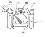
Fig. 1 schematically shows the structure of the motor of the vehicle that this control apparatus has been installed in first embodiment.
Fig. 2 is a flow chart of being carried out the program of control by ECU, implements this control apparatus of first embodiment.
Fig. 3 is first view of the fuel oil that sprays when being illustrated in intake stroke.
Fig. 4 is first view of the situation of air fuel mixture when being illustrated in igniting.
Fig. 5 is second view of the fuel oil that sprays when being illustrated in intake stroke.
Fig. 6 is second view of the situation of air fuel mixture when being illustrated in igniting.
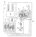
Fig. 7 schematically shows the structure of the motor of the vehicle that this control apparatus has been installed in a second embodiment.
Fig. 8 is a flow chart of being carried out the program of control by ECU, implements this control apparatus of second embodiment.
Fig. 9 is a flow chart of being carried out the program of control by ECU, implements this control apparatus of the 3rd embodiment.
Embodiment
Below with reference to accompanying drawing, embodiments of the invention are described.In the following description, identical part adopts identical mark and title identical with function.
First embodiment
With reference to figure 1, be described in the motor that the vehicle of this control apparatus has been installed among first embodiment.Illustrate in the present embodiment by electronic control unit (ECU) 200 executive routines as shown in fig. 1 and implement control apparatus.
Air is introduced in the cylinder 106 (firing chamber) and mixes with fuel oil in it.Cylinder 106 receives from sparger 108 and is directly injected to fuel oil in it.More specifically, sparger 108 has the injector nozzle that is positioned at cylinder 106.Fuel oil is injected from a side of the cylinder 106 of suction (or introducing) air.
Although the fuel injection timing is not limited to intake stroke, fuel oil is injected at intake stroke.In addition, in the present embodiment, motor 100 is described as having the direct-injection engine of sparger 108, and described sparger 108 has the nozzle bore that is positioned at cylinder 106, except the sparger 108 that is used for direct injection, also introduce the sparger that is used for port injection.
Air oil mixed gas in the cylinder 106 is lighted by spark plug 110 and burning thus.The air oil mixed gas of burning or exhaust purify by three-way catalyst 112, are discharged to outside vehicle then.Because air oil mixture combustion, piston 114 promote downwards and crankshaft 116 rotations.
The timings of the opening and closing of amount of fuel, air inlet and the exhaust valve of the timing of ECU200 control ignition, fuel injection timing, injection etc. are so that move motor 100 as required.ECU200 receives from the signal of the expression cam position of cam-angle sensor 300, from the signal of the angle of swing of the rotational speed of the expression crankshaft 116 (or motor) of crank angle sensor 302 and crankshaft 116 and from the signal of the shockproofness of the expression motor 100 of knock sensor 304.
ECU200 adopts signal, the chart that is stored in the storage (not shown) and the program that receives from sensor, control motor 100.In the present embodiment, ECU200 receives the signal that transmits from knock sensor 304 and whether detonation of detection of engine thus, and if ECU200 detect engine knock, then ECU200 proofreaies and correct the fuel injection timing.
With reference to figure 2, the ECU200 that implements the control apparatus in the present embodiment carries out the control program of being constructed in the following manner.
At step S100, based on as the rotational speed of the motor of parameter, the chart that load (moment of torsion) waits, the benchmark injection timing INJB of ECU200 calculating fuel oil.Calculate timing INJB, make fuel oil at intake stroke injected (for example, before: 90 ° to 180 °) at upper dead center (BTDC).In addition, the timing INJB that calculates is bigger, is suitable for injection timing faster.Because known general technology can calculate timing INJB, how not calculate timing INJB herein so do not specifically describe.
At S102, ECU200 is according to the signal that transmits from knock sensor 304, determines whether detonation of motor.Can determine whether detonation of motor by known general technology.When engine knock (at S102, "Yes"), program proceeds to S104.Otherwise (at S102, "No"), program proceeds to S106.
At S104, ECU200 calculates the corrected value that applies correction to injection timing: INJK (I)=INJK (I-1)+A, wherein, the corrected value of the previous calculating of INJK (I-1) expression, and A represents positive constant.More specifically, at S104, corrected value INJK (I) increases, and injection advance is introduced into.
At S106, ECU200 calculated correction value: INJK (I)=INJK (I-1)-B, wherein, B represents positive constant.More specifically, at S104, corrected value INJK (I) reduces, and delayed injection is introduced into.Then, program proceeds to S108.
At S108, ECU200 determines whether corrected value INJK (I) is not more than preset upper limit value INJK (X), and this CLV ceiling limit value is arranged to have a value, but the feasible flue dust that is produced by the fuel oil attached to piston 114 tops has the amount of the allowed band of falling into.Corrected value INJK (I) is not more than CLV ceiling limit value INJK (X) (at S108, "Yes"), and program proceeds to S110.Otherwise (at S108, "No"), program proceeds to S112.
At S110, ECU200 determines whether corrected value INJK (I) is not less than predetermined lower limit value INJK (Y), and this lower limit is arranged to have the value that the fuel oil that allows suitable vaporization and fuel oil and air mix suitably.If corrected value INJK (I) is not more than lower limit INJK (Y) (at S110, "Yes"), then program proceeds to S116.Otherwise (at S110, "No"), program proceeds to S114.
At S112, ECU200 is arranged on corrected value INJK (I) with CLV ceiling limit value INJK (X).Next, program proceeds to S116.At S114, ECU200 is arranged on corrected value INJK (I) with lower limit INJK (Y).Next, program proceeds to S116.
At S116, ECU200 is with benchmark injection timing INJB and corrected value INJK (I) addition, to obtain injection timing INJ.At this injection timing INJ, sparger 108 injected fuel.
To the operation of the ECU200 of the control apparatus of realizing present embodiment be described according to above-mentioned structure and flow chart below.
During motor 100 operation, calculate benchmark injection timing INJB (S100), and determine whether detonation (S102) of motor according to the signal that transmits from knock sensor 304.
As shown in Figure 3, if injection timing is set to postpone (perhaps near lower dead centre), injected and fuel oil that have a penetrating power enters cylinder 106 downwards.In this case, as shown in Figure 3, steam (the vertical stream (tumble) that rolls) is used for promoting clockwise, and when working as igniting, cylinder 106 inherent positions near the air inlet side have dense relatively air fuel ratio, and have rare relatively air fuel ratio in the position near exhaust side, as shown in Figure 4.
After lighting a fire, the flame propagation timing is subjected to the influence of temperature of air fuel ratio (the perhaps concentration of air oil mixed gas), cylinder 106 walls etc. largely.Usually, the flame propagation timing is the fastest in theoretical air fuel ratio.Therefore, help flame propagation timing faster than richer or rare air fuel ratio.In addition, it is slow that the wall of lower temperature helps to make the propagation of flame timing.Therefore, be easy to postpone towards having than the air inlet side of the air fuel ratio of richer with near the flame propagation timing of the wall of lower temperature.In this case, the air oil mixed gas of close air inlet side is compressed adiabaticly, and motor is easy in the detonation of air inlet side.
When engine knock (at S102, "Yes"), corrected value INJK (I) is calculated as INJK (I)=INJK (I-1)+A, with the increasing amount (S104) that correction is provided.If the corrected value INJK (I) that calculates is not more than CLV ceiling limit value INJK (X) (at S108, and be not less than lower limit INJK (Y) (at S110, "Yes") "Yes"),, then with benchmark injection timing INJB and corrected value INJK (I) addition, to obtain injection timing INJ (S116).Therefore, injection timing INJ in advance.
When injection timing INJ shifts to an earlier date or introduces injection advance, the top of the fuel impingement piston 114 that self-injection device 108 sprays, as shown in Figure 5.Therefore, most of the fuel oil of injection is brought to exhaust side.Therefore, as shown in Figure 6, when lighting a fire, exhaust side has dense relatively air fuel ratio, and the air inlet side has rare relatively air fuel ratio.In other words, air inlet side has the rare relatively air fuel ratio near chemically correct fuel.This can provide the timing of flame propagation faster towards the air inlet side, to prevent that motor is in the detonation of air inlet side.
Yet,, can produce the fume amount of increase attached to the fuel oil at piston 114 tops if introduced injection advance more than needs.Therefore, the CLV ceiling limit value of corrected value INJK (I) is set.
More specifically, if the corrected value INJK (I) that calculates is not less than CLV ceiling limit value INJK (X) (at S108, "No"), then CLV ceiling limit value INJK (X) is set to corrected value INJK (I).More specifically, the final corrected value INJK (I) that calculates is restricted to less than CLV ceiling limit value INJK (X).This can reduce the flue dust that exceeds admissible scope.
If motor non-detonating (at S102, "No") is then introduced delayed injection.More specifically, corrected value NJK (I) is calculated as IINJK (I-1)-B, and reduces (S106) thus.
If the corrected value INJK (I) that calculates is not more than CLV ceiling limit value INJK (X) (at S108, "Yes") and also be not less than lower limit INJK (Y) (at S110, "Yes"), then with benchmark injection timing INJB and corrected value INJK (I) addition, to obtain injection timing INJ (S116).Therefore, injection timing INJ postpones.
Yet,, can cause the insufficient mixing etc. of insufficient vaporization, fuel oil and the air of fuel oil if introduced delayed injection more than needs.Therefore, the lower limit of corrected value INJK (K) is set up.
More specifically, if the corrected value INJK (I) that calculates is not more than lower limit INJK (Y) (at S110, "No"), then lower limit INJK (Y) is set to corrected value INJK (I).More specifically, the final corrected value INJK (I) that calculates is restricted to and is at least lower limit INJK (Y).This can reduce the insufficient mixing etc. of insufficient vaporization, fuel oil and the air of fuel oil.
Therefore, when implementing ECU according to the control apparatus of present embodiment and detect engine knock, ECU introduces fuel injection in advance at intake stroke, with injection timing (injection timing perhaps is set approaches upper dead center) in advance.Therefore, the air inlet side in cylinder has the rare relatively air fuel ratio near chemically correct fuel, so that the timing of flame propagation faster towards the air inlet side to be provided.This helps to be reduced in the compressing adiabaticly and reduce detonation thus of air oil mixed gas of air inlet side.
Second embodiment
With reference to figure 7 and Fig. 8, the second embodiment of the present invention is described.In first embodiment, when detecting engine knock, introduce injection advance to reduce detonation at intake stroke.In the present embodiment, when detecting engine knock, and in cylinder, than slow, then introduce fuel injection in advance at intake stroke towards the flame propagation timing of exhaust side towards the flame propagation timing of air inlet side.
In cylinder, propagate timing by the ionic current detection device flame detection that is arranged in the cylinder.Describe among remaining part and first embodiment be provided with identical and function also identical.
With reference to figure 7, will the motor of having installed in it according to the vehicle of this control apparatus of present embodiment be described.As shown in the figure, cylinder 106 has air inlet side and exhaust side, and described air inlet side and exhaust side have the wall surface that is respectively arranged with ionic current detection device 306 and 308, and still device is not limited to and is positioned at this two positions.
In flame, the air oil mixed gas makes molecular ionization.Similarly, flame can conduct electricity.Similarly, when voltage was applied on the electrode that inserts the ionic current detection device 306,308 in the air oil mixed gas, electric current flowed.
In the present embodiment, ionic current detection device 306,308 detects and flows through the electric current of electrode, and will represent that the signal of testing result is input to ECU200.ECU200 detects electric current and flows timing as the flame propagation timing.
With reference to figure 8, implement to carry out the control program of structure in the following manner according to the ECU200 of control apparatus of the present invention.Notice that the identical step of describing among any and first embodiment of program step adopts identical mark.
At step S200, ECU200 detects the flame propagation timing TIN in the cylinder 106 of air inlet side from the signal from ionic current detection device 306 and 308, and detects the flame propagation timing TEX in the cylinder of exhaust side.
At step S202, ECU200 always in the signal of detonation sensor 304, whether detonation of detection of engine.If detonation (at S202, "Yes"), program proceeds to S204.Otherwise (in step S202, "No"), program proceeds to S116.
At S204, ECU200 determines whether timing TIN is slower than timing TEX.Slow if (at S204, "Yes"), program proceeds to S104.Otherwise (at S204, "No"), program proceeds to S106.
According to above-mentioned structure and flow chart, the operation of enforcement according to the ECU200 of control apparatus of the present invention is described below.
When motor 100 operations, calculate benchmark injection timing INJB (S100), and from signal, detect timing TIN and timing TEX (S200) from ionic current detection device 306 and 308.In addition, always in the signal of detonation sensor 304, determine whether detonation (S202) of motor.
If engine knock (at S202, "Yes"), and timing TIN thinks then that than timing TEX slow (at S204, "Yes") different flame propagation timings causes engine knock.
Therefore, corrected value INJK (I) is calculated as INJK (I-1)+A, and with the correcting value (S104) that increase is provided, and final injection timing INJ in advance.The timing of flame propagation faster can be obtained, and the detonation of the motor of air inlet side can be reduced in towards the air inlet side.
If engine knock (at S202, "Yes"), and timing TIN is than timing TEX fast (at S204, "No") thinks that then factor that nonflame is propagated timing has caused the detonation of motor.
In this case, corrected value INJK (I) is calculated as INJK (I-1)-B, and reduces (S106) thus, and final injection timing INJ postpones.
Therefore, when engine knock and towards the flame propagation timing TIN of air inlet side than when the flame propagation timing TEX of exhaust side is slow, enforcement causes injection advance according to the ECU of the control apparatus of present embodiment, to set injection timing faster (perhaps near upper dead center).This also can provide the similar effect that is effective to first embodiment.
The 3rd embodiment
With reference to figure 9, the third embodiment of the present invention is described.
In first and second embodiments, proofread and correct fuel injection timing, to reduce detonation at intake stroke.In the present embodiment, except injection timing, also proofread and correct ignition timing.Be provided with identical among remaining part and first or second embodiment and function also identical.
With reference to figure 9, enforcement is carried out the control program of structure in the following manner according to the ECU200 of the control apparatus of present embodiment.ECU carries out the program of describing among first or second embodiment, in addition also carries out below with the program of describing.
At S300, based on as the rotational speed of the motor of parameter, the chart that load (moment of torsion) waits, ECU200 calculating benchmark ignition timing SAB.Attention can be calculated benchmark ignition timing SAB by known general technology.
At S302, ECU200 is according to the signal that transmits from knock sensor 304, determines whether detonation of motor.Can determine whether detonation of motor by known general technology.When engine knock (at S302, "Yes"), program proceeds to S304.Otherwise (at S302, "No"), EOP end of program.
At S304, ECU200 determines whether the corrected value that applies correction to injection timing INJK (I) equals CLV ceiling limit value INJK (X).If equal (at S304, "Yes"), program proceeds to S306.Otherwise (in step S304, "No"), program proceeds to S308.
At S306, ECU200 calculates the corrected value that is applied, and is SAK (I-1)-C so that ignition timing SAK (I) is proofreaied and correct, and wherein, the corrected value and the C of the previous calculating of SAK (I-1) expression represent positive constant.More specifically, at S306, corrected value SAK (I) reduces, to introduce ignition lag.
At S308, ECU200 is calculated as SAK (I-1)+D with corrected value SAK (I), and wherein D represents positive constant.More specifically, at S308, corrected value SAK (I) increases, to introduce electronic spark advance.
At S310, ECU200 determines whether corrected value SAK (I) is not more than preset upper limit value SAK (X), and this CLV ceiling limit value is arranged to have a value, but the output (or moment of torsion) that this value makes motor 100 provide falls into allowed band.If corrected value SAK (I) is not more than CLV ceiling limit value SAK (X) (at S310, "Yes"), program proceeds to S314.Otherwise (at S310, "No"), program proceeds to S312.
At S312, ECU200 is arranged on corrected value SAK (I) with CLV ceiling limit value SAK (X).Next, program proceeds to S314.At S314, ECU200 is with benchmark ignition timing SAB and corrected value SAK (I) addition, so that ignition timing SA to be provided.In this ignition timing, cylinder 106 is lighted the air oil mixed gas in it.
To the operation of the ECU200 of the control apparatus of realizing present embodiment be described according to above-mentioned structure and flow chart below.
During motor 100 operation, calculate benchmark injection timing SAB (S300), and determine whether detonation (S302) of motor according to the signal that transmits from knock sensor 304.
If engine knock (302, "Yes") determines then whether corrected value INJK (I) equals CLV ceiling limit value INJK (X) (S304).Corrected value INJK (I) equals CLV ceiling limit value INJK (X) (at S304, "Yes"), thinks that then this shows that can not shift to an earlier date injection timing INJ again prevents engine knock.
Therefore, corrected value SAK (I) is calculated as SAK (I-1)-C, and reduces (S306) thus.In this case, corrected value SAK (I) needs acquisition one to be not more than the value (at S310, "Yes") of CLV ceiling limit value SAK (X).Therefore, with corrected value SAK (I) addition of benchmark ignition timing SAB and calculating, with retarded spark timing SA.
By contrast, corrected value INJK (I) is different from CLV ceiling limit value INJK (X) (at S304, "Yes"), that is, corrected value INJK (I) is less than CLV ceiling limit value INJK (X), thinks then that this shows can shift to an earlier date injection timing INJ, to prevent engine knock.
In this case,, corrected value SAK (I) is calculated as SAK (I-1)+D, and increases (S308) thus in order to introduce electronic spark advance.If the corrected value SAK (I) that calculates is not more than CLV ceiling limit value SAK (X) (at S310, "Yes"), then with corrected value SAK (I) addition of benchmark ignition timing SAB and calculating, with acquisition ignition timing SA (S314).In this case, introduce electronic spark advance.This can prevent that motor 100 provides the output that reduces (or moment of torsion) owing to introduced ignition lag.
If ignition timing SA more than needs in advance, may damage the burning of air oil mixed gas, and the output (or moment of torsion) that causes motor 100 to provide reducing.For prevent more than needs in advance, if corrected value SAK (I) greater than CLV ceiling limit value SAK (X) (at S310, "No"), then CLV ceiling limit value SAK (X) is set to corrected value SAK (I) (S312) and be limited thus.This can prevent ignition timing more than needs in advance, therefore prevent that motor 100 from providing the output that reduces (or moment of torsion).Attention can limit corrected value SAK (I) and be not less than lower limit SAK (Y) except restriction corrected value SAK (I) is not more than the CLV ceiling limit value SAK (X).
Therefore, when the ECU200 of the control apparatus of implementing present embodiment detects engine knock, apply corrected value INJK (I), so that injection timing is proofreaied and correct to equaling CLV ceiling limit value INJK (X), ECU200 introduces ignition lag.When not controlling injection timing when preventing engine knock, this can further prevent engine knock.
Other embodiment
In first and second embodiments, introduce fuel injection in advance at intake stroke.Perhaps, fuel oil can spray twice, that is, in intake stroke and compression stroke, if engine knock can be introduced the fuel injection delay in compression stroke, and if the motor non-detonating, can introduce fuel injection in advance in compression stroke.This also can provide to first embodiment in the similar effect of effect that obtains.
In addition, postpone, the upper limit (with relevant in advance restriction) and the lower limit (with postponing relevant restriction) of injection timing then can be provided if introduce fuel injection in compression stroke.This also can provide to first embodiment in the similar effect of effect that obtains.
In addition, be used for injection timing in compression stroke if introduce this upper and lower bound, and engine knock, and injection timing then can be introduced ignition lag to prevent engine knock corresponding to lower limit.This also can provide to the 3rd embodiment in the similar effect of effect that obtains.
In addition, if engine knock, then postpone except introducing fuel injection in compression stroke, fuel oil can be injected with the amount (the perhaps amount of ratio increase) that increases in compression stroke, if and the motor non-detonating, then fuel oil can be injected with the amount (the perhaps amount of ratio minimizing) that reduces in compression stroke.This also can provide to first embodiment in the similar effect of effect that obtains.
In addition, if fuel oil is injected with the amount that increases in compression stroke, then this amount also can be provided with upper and lower bound.This also can provide to first embodiment in the similar effect of effect that obtains.
In addition, be used for the amount of fuel of spraying, and engine knock, and injection timing then can introduce ignition lag corresponding to CLV ceiling limit value, to prevent engine knock in compression stroke if introduced this upper and lower bound.This also can provide to the 3rd embodiment in the similar effect of effect that obtains.
Though the present invention is described in detail and explains, clearly this only is used for explanation and for example but not be used to limit, and design of the present invention and scope only limit by appending claims.
Claims (50)
1. the control apparatus of an internal-combustion engine, described internal-combustion engine comprises the injection apparatus of fuel direct injection being gone into cylinder, described control apparatus comprises:
Detection device, it is used for the detection of engine detonation; And
Control gear, it is when detecting engine knock, and being used to control described injection apparatus provides flame propagation timing faster towards the air inlet side in described cylinder.
2. control apparatus as claimed in claim 1, wherein, described control gear comprises and is used to control described injection apparatus increasing the air fuel ratio of the described air inlet side in described cylinder, thereby the device of flame propagation timing faster is provided towards described air inlet side in described cylinder.
3. control apparatus as claimed in claim 2, wherein, described control gear comprises and is used for introducing the device that fuel injection shifts to an earlier date at intake stroke.
4. control apparatus as claimed in claim 3 also comprises being used for the fuel injection timing is restricted to the device that is no earlier than the first predetermined injection timing and is not later than the second predetermined injection timing.
5. control apparatus as claimed in claim 4 comprises that also when detecting described engine knock and described injection timing be described first just constantly, is used to introduce the device of ignition lag.
6. control apparatus as claimed in claim 2, wherein:
Described cylinder reception is cut apart and is therefore sprayed twice fuel oil at intake stroke and compression stroke; And
Described control gear comprises and is used for introducing the device that fuel injection postpones in described compression stroke.
7. control apparatus as claimed in claim 6 also comprises being used for the fuel injection timing is restricted to the device that is no earlier than the first predetermined injection timing and is not later than the second predetermined injection timing.
8. control apparatus as claimed in claim 7 comprises that also when detecting described engine knock and described injection timing be described second just constantly, is used to introduce the device of ignition lag.
9. control apparatus as claimed in claim 6, wherein, described control gear comprises and is used for introducing the described device that described fuel injection postpones in described compression stroke, and being used in addition is increased in the device of the amount of fuel that described compression stroke sprays.
10. control apparatus as claimed in claim 9 also comprises being used for described amount is limited in the device that is not less than first prearranging quatity and is not more than second prearranging quatity.
11. control apparatus as claimed in claim 10 comprises that also when detecting described engine knock and described amount be described second when amount, is used to introduce the device of ignition lag.
12. the control apparatus of an internal-combustion engine, described internal-combustion engine comprises the injection apparatus of fuel direct injection being gone into cylinder, and described control apparatus comprises:
Detection device, it is used to detect the flame propagation timing in described cylinder; And
Control gear, it controls described injection apparatus, with the flame propagation timing in the described cylinder of box lunch when slower than the flame propagation timing in the described cylinder towards exhaust side towards the air inlet side, be used to make in the described cylinder towards the flame propagation timing of air inlet side in advance.
13. control apparatus as claimed in claim 12, wherein, described control gear comprises and is used to control described injection apparatus increasing the air fuel ratio of the described air inlet side in described cylinder, thereby the device of flame propagation timing faster is provided towards described air inlet side in described cylinder.
14. control apparatus as claimed in claim 13, wherein, described control gear comprises and is used for introducing the device that fuel injection shifts to an earlier date at intake stroke.
15. control apparatus as claimed in claim 14 also comprises being used for the fuel injection timing is restricted to the device that is no earlier than the first predetermined injection timing and is not later than the second predetermined injection timing.
16. control apparatus as claimed in claim 15 comprises that also when detecting described engine knock and described injection timing be described first just constantly, is used to introduce the device of ignition lag.
17. control apparatus as claimed in claim 13, wherein:
Described cylinder reception is cut apart and is sprayed twice fuel oil at intake stroke and compression stroke thus; And
Described control gear comprises and is used for introducing the device that fuel injection postpones in described compression stroke.
18. control apparatus as claimed in claim 17 also comprises being used for the fuel injection timing is restricted to the device that is no earlier than the first predetermined injection timing and is not later than the second predetermined injection timing.
19. control apparatus as claimed in claim 18 comprises that also when detecting described engine knock and described injection timing be described second just constantly, is used to introduce the device of ignition lag.
20. control apparatus as claimed in claim 17, wherein, described control gear comprises and is used for introducing the described device that described fuel injection postpones in described compression stroke, and being used in addition is increased in the device of the amount of fuel that described compression stroke sprays.
21. control apparatus as claimed in claim 20 also comprises being used for described amount is limited in the device that is not less than first prearranging quatity and is not more than second prearranging quatity.
22. control apparatus as claimed in claim 21 comprises that also when detecting described engine knock and described amount be described second when amount, is used to introduce the device of ignition lag.
23. control apparatus as claimed in claim 12 wherein, is provided with a plurality of described detection devices in described cylinder.
24. control apparatus as claimed in claim 23, wherein, described detection device is separately positioned on interior two positions near described air inlet side and described exhaust side of described cylinder.
25. control apparatus as claimed in claim 24, wherein, described detection device is the ionic current detection device.
26. the control apparatus of an internal-combustion engine, described internal-combustion engine comprises the sparger of fuel direct injection being gone into cylinder, and described control apparatus comprises:
Detector, it is used for the detection of engine detonation; And
Controller, it is when detecting engine knock, and being used to control described sparger provides flame propagation timing faster towards the air inlet side in described cylinder.
27. control apparatus as claimed in claim 26, wherein, described controller is controlled described sparger, with the air fuel ratio of the described air inlet side of increase in described cylinder, thereby provides flame propagation timing faster towards described air inlet side in described cylinder.
28. control apparatus as claimed in claim 27, wherein, described controller is introduced fuel injection in advance at intake stroke.
29. control apparatus as claimed in claim 28 also comprises the fuel injection timing is restricted to the injection timing limiter that is no earlier than the first predetermined injection timing and is not later than the second predetermined injection timing.
30. control apparatus as claimed in claim 29 comprises that also when detecting described engine knock and described injection timing be described first just constantly, introduces the ignition lag device of ignition lag.
31. control apparatus as claimed in claim 27, wherein:
Described cylinder reception is cut apart and is sprayed twice fuel oil at intake stroke and compression stroke thus; And
Described controller is introduced fuel injection in described compression stroke and is postponed.
32. control apparatus as claimed in claim 31 also comprises the fuel injection timing is restricted to the injection timing limiter that is no earlier than the first predetermined injection timing and is not later than the second predetermined injection timing.
33. control apparatus as claimed in claim 32 comprises that also when detecting described engine knock and described injection timing be described second just constantly, introduces the ignition lag device of ignition lag.
34. control apparatus as claimed in claim 31, wherein, described controller is introduced described fuel injection in described compression stroke and is postponed, and in addition, increases the amount of fuel of spraying in described compression stroke.
35. control apparatus as claimed in claim 34 also comprises described amount is limited in the limiter that is not less than first prearranging quatity and is not more than second prearranging quatity.
36. control apparatus as claimed in claim 35 comprises that also when detecting described engine knock and described amount be described second when amount, introduces the ignition lag device of ignition lag.
37. the control apparatus of an internal-combustion engine, described internal-combustion engine comprises the sparger of fuel direct injection being gone into cylinder, and described control apparatus comprises:
Detector, it is used to detect the flame propagation timing in described cylinder; And
Controller, it controls described sparger, with the flame propagation timing in the described cylinder of box lunch when slower than the flame propagation timing in the described cylinder towards exhaust side towards the air inlet side, make in the described cylinder towards the flame propagation timing of air inlet side in advance.
38. control apparatus as claimed in claim 37, wherein, described controller is controlled described sparger, with the air fuel ratio of the described air inlet side of increase in described cylinder, thereby provides flame propagation timing faster towards described air inlet side in described cylinder.
39. control apparatus as claimed in claim 38, wherein, described controller is introduced fuel injection in advance at intake stroke.
40. control apparatus as claimed in claim 39 also comprises being used for the fuel injection timing is restricted to the injection timing limiter that is no earlier than the first predetermined injection timing and is not later than the second predetermined injection timing.
41. control apparatus as claimed in claim 40 comprises that also when detecting described engine knock and described injection timing be described first just constantly, introduces the ignition lag device of ignition lag.
42. control apparatus as claimed in claim 38, wherein:
Described cylinder reception is cut apart and is sprayed twice fuel oil at intake stroke and compression stroke thus; And
Described controller is introduced fuel injection in described compression stroke and is postponed.
43. control apparatus as claimed in claim 42 also comprises the fuel injection timing is restricted to the injection timing limiter that is no earlier than the first predetermined injection timing and is not later than the second predetermined injection timing.
44. control apparatus as claimed in claim 43 comprises that also when detecting described engine knock and described injection timing be described second just constantly, introduces the ignition lag device of ignition lag.
45. control apparatus as claimed in claim 42, wherein, described controller is introduced described fuel injection in described compression stroke and is postponed, and in addition, increases the amount of fuel of spraying in described compression stroke.
46. control apparatus as claimed in claim 45 also comprises described amount is limited in the limiter that is not less than first prearranging quatity and is not more than second prearranging quatity.
47. control apparatus as claimed in claim 46 comprises that also when detecting described engine knock and described amount be described second when amount, introduces the ignition lag device of ignition lag.
48. control apparatus as claimed in claim 37 wherein, is provided with a plurality of described detectors in described cylinder.
49. control apparatus as claimed in claim 48, wherein, described detector is separately positioned on interior two positions near described air inlet side and described exhaust side of described cylinder.
50. control apparatus as claimed in claim 49, wherein, described detector is the ionic current detection device.
Applications Claiming Priority (2)
| Application Number | Priority Date | Filing Date | Title |
|---|---|---|---|
| JP2004377397A JP2006183548A (en) | 2004-12-27 | 2004-12-27 | Control device for internal combustion engine |
| JP377397/2004 | 2004-12-27 |
Publications (1)
| Publication Number | Publication Date |
|---|---|
| CN101263288A true CN101263288A (en) | 2008-09-10 |
Family
ID=35431620
Family Applications (1)
| Application Number | Title | Priority Date | Filing Date |
|---|---|---|---|
| CNA2005800449664A Pending CN101263288A (en) | 2004-12-27 | 2005-09-27 | Control device for internal combustion engine |
Country Status (5)
| Country | Link |
|---|---|
| US (1) | US7246600B2 (en) |
| EP (1) | EP1831522A1 (en) |
| JP (1) | JP2006183548A (en) |
| CN (1) | CN101263288A (en) |
| WO (1) | WO2006070520A1 (en) |
Cited By (5)
| Publication number | Priority date | Publication date | Assignee | Title |
|---|---|---|---|---|
| CN102518522A (en) * | 2011-12-23 | 2012-06-27 | 清华大学 | Split cylinder independent closed loop control method for homogeneous charge compression ignition (HCCI) combustion on basis of knock sensor |
| CN103443430A (en) * | 2011-03-31 | 2013-12-11 | 三菱重工业株式会社 | Method and device for controlling pilot injection timing when engine combustion diagnosis signal is abnormal |
| CN103590914A (en) * | 2012-08-17 | 2014-02-19 | 福特环球技术公司 | Injection timing |
| CN107165736A (en) * | 2010-07-29 | 2017-09-15 | 福特环球技术公司 | Engine system and its method of operation |
| CN107816390A (en) * | 2016-09-13 | 2018-03-20 | 卡特彼勒公司 | Automatic calibration system and method for dual fuel internal combustion engine |
Families Citing this family (30)
| Publication number | Priority date | Publication date | Assignee | Title |
|---|---|---|---|---|
| JP4353216B2 (en) * | 2006-08-04 | 2009-10-28 | トヨタ自動車株式会社 | In-cylinder injection spark ignition internal combustion engine |
| JP2009024682A (en) * | 2007-07-24 | 2009-02-05 | Denso Corp | Control device for spray guide type cylinder injection internal combustion engine |
| US8150602B2 (en) * | 2007-11-08 | 2012-04-03 | Honeywell International Inc. | Method and system for estimating in-cylinder pressure and knocking utilizing an in-cylinder pressure sensor |
| US9157825B2 (en) * | 2008-05-01 | 2015-10-13 | GM Global Technology Operations LLC | Engine knock diagnostic |
| JP5182157B2 (en) * | 2009-03-04 | 2013-04-10 | 日産自動車株式会社 | Diesel engine control device |
| US7861684B2 (en) | 2009-05-14 | 2011-01-04 | Advanced Diesel Concepts Llc | Compression ignition engine and method for controlling same |
| US8807115B2 (en) | 2009-05-14 | 2014-08-19 | Advanced Diesel Concepts, Llc | Compression ignition engine and method for controlling same |
| US9284906B2 (en) * | 2011-06-08 | 2016-03-15 | GM Global Technology Operations LLC | Combustion phasing control methodology in HCCI combustion |
| CN105143649B (en) * | 2013-03-11 | 2019-03-08 | 韦恩州立大学 | Prediction correction in internal combustion engine |
| US11078860B2 (en) | 2013-03-11 | 2021-08-03 | Wayne State University | Predictive correction in internal combustion engines |
| US9441556B2 (en) * | 2013-03-15 | 2016-09-13 | GM Global Technology Operations LLC | Noise updating systems and methods |
| JP5951537B2 (en) * | 2013-03-19 | 2016-07-13 | 三菱重工業株式会社 | Gas engine combustion control device |
| JP6098446B2 (en) * | 2013-09-04 | 2017-03-22 | トヨタ自動車株式会社 | Engine control device |
| US9556810B2 (en) | 2014-12-31 | 2017-01-31 | General Electric Company | System and method for regulating exhaust gas recirculation in an engine |
| US9752949B2 (en) | 2014-12-31 | 2017-09-05 | General Electric Company | System and method for locating engine noise |
| US9803567B2 (en) | 2015-01-07 | 2017-10-31 | General Electric Company | System and method for detecting reciprocating device abnormalities utilizing standard quality control techniques |
| US9874488B2 (en) | 2015-01-29 | 2018-01-23 | General Electric Company | System and method for detecting operating events of an engine |
| US9528445B2 (en) | 2015-02-04 | 2016-12-27 | General Electric Company | System and method for model based and map based throttle position derivation and monitoring |
| US9903778B2 (en) | 2015-02-09 | 2018-02-27 | General Electric Company | Methods and systems to derive knock sensor conditions |
| US9791343B2 (en) | 2015-02-12 | 2017-10-17 | General Electric Company | Methods and systems to derive engine component health using total harmonic distortion in a knock sensor signal |
| US10001077B2 (en) | 2015-02-19 | 2018-06-19 | General Electric Company | Method and system to determine location of peak firing pressure |
| US9915217B2 (en) | 2015-03-05 | 2018-03-13 | General Electric Company | Methods and systems to derive health of mating cylinder using knock sensors |
| US9695761B2 (en) | 2015-03-11 | 2017-07-04 | General Electric Company | Systems and methods to distinguish engine knock from piston slap |
| US9435244B1 (en) | 2015-04-14 | 2016-09-06 | General Electric Company | System and method for injection control of urea in selective catalyst reduction |
| US9784231B2 (en) | 2015-05-06 | 2017-10-10 | General Electric Company | System and method for determining knock margin for multi-cylinder engines |
| US9933334B2 (en) | 2015-06-22 | 2018-04-03 | General Electric Company | Cylinder head acceleration measurement for valve train diagnostics system and method |
| US9784635B2 (en) | 2015-06-29 | 2017-10-10 | General Electric Company | Systems and methods for detection of engine component conditions via external sensors |
| US10393609B2 (en) | 2015-07-02 | 2019-08-27 | Ai Alpine Us Bidco Inc. | System and method for detection of changes to compression ratio and peak firing pressure of an engine |
| US9897021B2 (en) | 2015-08-06 | 2018-02-20 | General Electric Company | System and method for determining location and value of peak firing pressure |
| US10760543B2 (en) | 2017-07-12 | 2020-09-01 | Innio Jenbacher Gmbh & Co Og | System and method for valve event detection and control |
Family Cites Families (28)
| Publication number | Priority date | Publication date | Assignee | Title |
|---|---|---|---|---|
| DE3139000C2 (en) * | 1980-10-17 | 1986-03-06 | Michael G. Dipl.-Ing. ETH Rolle May | Method and control device for adjusting the ignition point in a spark-ignition internal combustion engine |
| JPS6011651A (en) * | 1983-07-01 | 1985-01-21 | Nissan Motor Co Ltd | Method of controlling knocking |
| JPS6260964A (en) * | 1985-09-10 | 1987-03-17 | Nissan Motor Co Ltd | Combustion controller for internal combustion engine |
| US5157613A (en) * | 1987-01-14 | 1992-10-20 | Lucas Industries Public Limited Company | Adaptive control system for an engine |
| US5163405A (en) * | 1989-06-29 | 1992-11-17 | Orbital Engine Company (Australia) Pty. Ltd. | Knock control by reduction of injection period |
| JPH04187851A (en) * | 1990-11-20 | 1992-07-06 | Toyota Motor Corp | Cylinder direct-injection type spark ignition engine |
| JP2836353B2 (en) | 1992-03-23 | 1998-12-14 | トヨタ自動車株式会社 | In-cylinder internal combustion engine |
| US5327864A (en) * | 1993-03-08 | 1994-07-12 | Chrysler Corporation | Stratified-charge internal combustion engine with fuel injection and dual ignition |
| JP3092763B2 (en) | 1993-04-16 | 2000-09-25 | ダイハツ工業株式会社 | Ion current detection method |
| JPH07158500A (en) | 1993-12-06 | 1995-06-20 | Hitachi Ltd | Evaluation method for engine flame |
| JP3809920B2 (en) * | 1995-08-11 | 2006-08-16 | 株式会社新エィシーイー | Fuel injection control device for diesel engine |
| JP3544257B2 (en) * | 1995-11-07 | 2004-07-21 | ヤマハ発動機株式会社 | High compression ratio direct injection internal combustion engine |
| SE9701780L (en) * | 1997-05-12 | 1998-05-25 | Mecel Ab | Method for feedback control of injection timing in internal combustion engines |
| IT1294853B1 (en) * | 1997-09-09 | 1999-04-23 | Fiat Ricerche | METHOD OF DETONATION DETECTION AND CONTROL FOR AN INTERNAL COMBUSTION ENGINE. |
| JP4126738B2 (en) | 1997-12-12 | 2008-07-30 | 日産自動車株式会社 | In-cylinder injection spark ignition engine |
| JPH11182288A (en) | 1997-12-18 | 1999-07-06 | Sanshin Ind Co Ltd | Control device for direct fuel injection type engine |
| DE19936201A1 (en) * | 1999-07-31 | 2001-02-08 | Bosch Gmbh Robert | Method for operating an internal combustion engine |
| JP2001248482A (en) | 2000-02-29 | 2001-09-14 | Hitachi Ltd | Control device for cylinder injection type internal combustion engine |
| JP2002054486A (en) | 2000-08-10 | 2002-02-20 | Honda Motor Co Ltd | Control device for internal combustion engine |
| JP2002070558A (en) * | 2000-09-01 | 2002-03-08 | Nissan Motor Co Ltd | Compression self-ignition type gasoline internal combustion engine |
| WO2002020957A1 (en) * | 2000-09-04 | 2002-03-14 | Hitachi, Ltd. | Cylinder injection type spark ignition engine |
| LU90727B1 (en) * | 2001-02-09 | 2002-08-12 | Delphi Tech Inc | Method for controlling a stratified combustion mode in an engine |
| JP4038999B2 (en) | 2001-05-14 | 2008-01-30 | 日産自動車株式会社 | Control device for direct-injection spark ignition engine |
| JP4178386B2 (en) * | 2002-03-28 | 2008-11-12 | 株式会社デンソー | Control device for knocking suppression of internal combustion engine |
| JP3827083B2 (en) | 2002-11-08 | 2006-09-27 | 三菱電機株式会社 | Knock detection device for internal combustion engine |
| JP4094936B2 (en) * | 2002-11-15 | 2008-06-04 | ヤマハマリン株式会社 | Knocking avoidance control system for 4-cycle engine for outboard motor |
| JP2006046084A (en) * | 2004-07-30 | 2006-02-16 | Toyota Motor Corp | Ignition timing controller for internal combustion engine |
| JP4462079B2 (en) * | 2004-11-11 | 2010-05-12 | トヨタ自動車株式会社 | Control device for internal combustion engine |
-
2004
- 2004-12-27 JP JP2004377397A patent/JP2006183548A/en active Pending
-
2005
- 2005-09-27 WO PCT/JP2005/018255 patent/WO2006070520A1/en active Application Filing
- 2005-09-27 EP EP05787523A patent/EP1831522A1/en not_active Withdrawn
- 2005-09-27 CN CNA2005800449664A patent/CN101263288A/en active Pending
- 2005-09-28 US US11/236,766 patent/US7246600B2/en not_active Expired - Fee Related
Cited By (10)
| Publication number | Priority date | Publication date | Assignee | Title |
|---|---|---|---|---|
| CN107165736A (en) * | 2010-07-29 | 2017-09-15 | 福特环球技术公司 | Engine system and its method of operation |
| CN107165736B (en) * | 2010-07-29 | 2020-02-11 | 福特环球技术公司 | Engine system and method for operating the same |
| CN103443430A (en) * | 2011-03-31 | 2013-12-11 | 三菱重工业株式会社 | Method and device for controlling pilot injection timing when engine combustion diagnosis signal is abnormal |
| CN103443430B (en) * | 2011-03-31 | 2016-01-20 | 三菱重工业株式会社 | Pilot injection time control method during the combustion diagnosis abnormal signal of motor and device |
| CN102518522A (en) * | 2011-12-23 | 2012-06-27 | 清华大学 | Split cylinder independent closed loop control method for homogeneous charge compression ignition (HCCI) combustion on basis of knock sensor |
| CN102518522B (en) * | 2011-12-23 | 2014-09-24 | 清华大学 | Split cylinder independent closed loop control method for homogeneous charge compression ignition (HCCI) combustion on basis of knock sensor |
| CN103590914A (en) * | 2012-08-17 | 2014-02-19 | 福特环球技术公司 | Injection timing |
| CN103590914B (en) * | 2012-08-17 | 2018-06-12 | 福特环球技术公司 | Injection timing |
| CN107816390A (en) * | 2016-09-13 | 2018-03-20 | 卡特彼勒公司 | Automatic calibration system and method for dual fuel internal combustion engine |
| CN107816390B (en) * | 2016-09-13 | 2021-12-28 | 卡特彼勒公司 | Automatic calibration system and method for dual fuel internal combustion engine |
Also Published As
| Publication number | Publication date |
|---|---|
| US7246600B2 (en) | 2007-07-24 |
| JP2006183548A (en) | 2006-07-13 |
| US20060137648A1 (en) | 2006-06-29 |
| EP1831522A1 (en) | 2007-09-12 |
| WO2006070520A1 (en) | 2006-07-06 |
Similar Documents
| Publication | Publication Date | Title |
|---|---|---|
| CN101263288A (en) | Control device for internal combustion engine | |
| KR100272024B1 (en) | Exhaust temperature rising apparatus of cylinder in spray type internal combustion engine | |
| KR100683540B1 (en) | Fuel injection control apparatus and fuel injection control method for internal combustion engine | |
| EP1042594B1 (en) | Temperature control of emission control devices coupled to direct injection engines | |
| KR101158998B1 (en) | Control apparatus and control method for internal combustion engine | |
| CA2539905C (en) | Method and apparatus for pilot fuel introduction and controlling combustion in gaseous-fuelled internal combustion engine | |
| US6095102A (en) | Dual fuel engine which creates a substantially homogeneous mixture of gaseous fuel, air, and pilot fuel during a compression stroke | |
| US8720416B2 (en) | Methods and apparatus to detect and inhibit low-speed pre-ignition in an engine | |
| CN106050451B (en) | The control device of internal combustion engine | |
| CN105545516B (en) | The control device of internal combustion engine | |
| CN206221056U (en) | Internal combustion engine | |
| US20020053336A1 (en) | Engine control system for constrolling in-cylinder fuel injection engine | |
| KR20010085216A (en) | Cylinder injection engine and control apparatus and method thereof | |
| KR950019135A (en) | Control device and method of internal combustion engine | |
| EP0937883B1 (en) | Method to control injection in a compression-ignition engine | |
| JP6112195B2 (en) | Internal combustion engine control system | |
| CN100422534C (en) | Combustion control system and method for direct injection spark ignition internal combustion engine | |
| WO2016035276A1 (en) | Internal combustion engine | |
| JP2022107648A (en) | Binary fuel large-sized diesel engine operation method and binary fuel large-sized diesel engine | |
| EP1471241B1 (en) | Fuel injection control device | |
| CN101415927A (en) | Method for operating an internal combustion engine | |
| KR101542540B1 (en) | Control device of internal combustion engine with supercharger | |
| CN101338694A (en) | Method and system for in-cylinder direct-injection gasoline engine stratified equivalent proportion combustion | |
| WO2007019649A1 (en) | Engine management systems and method | |
| JP2007192235A (en) | Control device and method for spark ignition internal combustion engine |
Legal Events
| Date | Code | Title | Description |
|---|---|---|---|
| C06 | Publication | ||
| PB01 | Publication | ||
| C10 | Entry into substantive examination | ||
| SE01 | Entry into force of request for substantive examination | ||
| C02 | Deemed withdrawal of patent application after publication (patent law 2001) | ||
| WD01 | Invention patent application deemed withdrawn after publication |
Open date: 20080910 |