CN101092108B - Right suspension installation of saloon car engine - Google Patents
Right suspension installation of saloon car engine Download PDFInfo
- Publication number
- CN101092108B CN101092108B CN200710092457A CN200710092457A CN101092108B CN 101092108 B CN101092108 B CN 101092108B CN 200710092457 A CN200710092457 A CN 200710092457A CN 200710092457 A CN200710092457 A CN 200710092457A CN 101092108 B CN101092108 B CN 101092108B
- Authority
- CN
- China
- Prior art keywords
- base plate
- car engine
- plate
- board
- right suspension
- Prior art date
- Legal status (The legal status is an assumption and is not a legal conclusion. Google has not performed a legal analysis and makes no representation as to the accuracy of the status listed.)
- Expired - Fee Related
Links
Images


Abstract
The invention relates to a car engine right suspending device that includes welding flat board, buffer block, location limited screw and location limited nut. The feature is that it also includes a U shaped vertical board, which includes two side vertical boards and main vertical board. The welding flat board is welded in the slot rounded by the three vertical boards. The sides of side vertical boards are buckled outside to form reinforced plate, and the bottoms are buckled outside to 90 degree to form bottom board. The bottom board is fixed to reinforced board. Bold installing hole is set on the bottom board. The invention could enhance bearing capacity of right suspending device, and has high rigidity, intension and stability. It also has damping effect to vertical force and side force.
Description
Technical field
The invention belongs to the car parts, specifically, is a kind of right suspension installation of saloon car engine that is used to install motorcar engine.
Background technology
The car of existing a lot of same brands, different model, all be to adopt identical body structure, the driving engine that cooperates different model, just kept the body structure size constant, but the size dimension of driving engine, even certain variation all taken place in shape and structure, thereby makes the assembly relation between driving engine and the vehicle body occur changing, and is re-engining on the basis of LF7160 as Lifan LF7130 vehicle.The size of engine of original LF7160 is bigger, close together between driving engine and the motorcar body right vertical beam, only need adopting base plate of screw retention on the right vertical beam, again a bump rubber be installed on base plate, the spacing screw rod that the bump rubber top is fixing, the shaft of this spacing screw rod up and be set with stop nut, suit loading arm and auxiliary suspension are connected with engine case on the spacing screw rod, play the effect of stationary engine; But the size of engine of LF7130 vehicle is less, and the distance between driving engine and the motorcar body right vertical beam is far away, and auxiliary suspension has been cancelled in the loading arm overstriking that is lengthened out simultaneously, and is therefore just higher to the requirement of intensity, rigidity and the stationarity of driving engine right suspension installation.
The shortcoming of prior art is: intensity, rigidity and the stationarity of existing base plate, bump rubber and spacing screw rod mounting structure are low, and weight capacity is poor, can't support driving engine at a distance.
Summary of the invention
The purpose of this invention is to provide the strong right suspension installation of saloon car engine of a kind of weight capacity, have high intensity, rigidity and stationarity, can support driving engine at a distance.
For achieving the above object, a kind of right suspension installation of saloon car engine of the present invention, comprise welding plate, the bump rubber of on welding plate, installing, the spacing screw rod that the bump rubber top is fixing, the shaft of this spacing screw rod is positioned at the top of described bump rubber, and be set with stop nut, its key is: also comprise a U-shaped riser, this U-shaped riser comprises the cant board and the middle main riser on both sides, be welded with described welding plate in the groove that three risers surround, the side of described two cant boards is bent to form brace panel to external symmetry, the base of two cant boards forms base plate for 90 ° to the external symmetry bending, this base plate is captiveed joint with the brace panel base, and described base plate is provided with screw mounting hole.
Increase the U-shaped riser, and be fixed on the motorcar body right vertical beam, the intensity, rigidity and the stationarity that have improved mounting bracket are low, and the U-shaped riser is punch forming, have easy to process, the advantage that cost is low.
The side of described two cant boards forms brace panels for 90 ° to external symmetry bending, after 90 ° of the lower end bendings of this brace panel and be fitted on the described base plate.
A described base plate is provided with steel plate, and this steel plate is parallel with described brace panel, one side on the cant board that is welded on the U-shaped riser of steel plate, 90 ° of the lower end of steel plate bendings also are fitted on the described base plate.
Brace panel and steel plate can both improve the ability to bear of U-shaped riser, satisfy the needed intensity of engine installation, rigidity and stationarity requirement.
Described base plate is provided with three screw mounting holes, and described screw mounting hole passes the lower end kink of brace panel and the lower end kink of steel plate respectively.
Three screws are respectively with brace panel and U-shaped riser, and the base of steel plate and U-shaped riser is fixed on the motorcar body right vertical beam, increase stability.
The top of described bump rubber is installed with " U " shape buffer rack, should be separately installed with rubber block in " U " shape buffer rack stile outside, and described rubber block is connected to respectively on two cant boards of described U-shaped riser.
A cant board top of described U-shaped riser outwards generates 14 °~24 ° bendings, and with outwards 14 °~24 ° bendings of generation of a stile of this cant board cooresponding described " U " shape buffer rack, and clamping has described rubber block between the two.
Bump rubber can play damping to longitudinal stress, and rubber block can be to the effect of stressed damping of side direction.
Remarkable result of the present invention is: strengthen the weight capacity of right suspension installation of saloon car engine, make it have high intensity, rigidity and stationarity, can support driving engine at a distance, simultaneously, can also play the effect of damping to longitudinal stress and lateral force.
Description of drawings
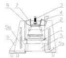
Fig. 1 is a structural representation of the present invention;
Fig. 2 is the block diagram of U-shaped riser;
Fig. 3 is the birds-eye view after the U-shaped riser is installed steel plate and welding plate;
Fig. 4 is a positive block diagram behind U-shaped riser installation steel plate and the welding plate;
Fig. 5 is the block diagram at the back side behind U-shaped riser installation steel plate and the welding plate;
Fig. 6 is the structural representation of motorcar body right vertical beam;
Fig. 7 is that the present invention is installed in the structural representation on the right vertical beam.
The specific embodiment
Below in conjunction with the drawings and specific embodiments the present invention is described in further detail.
As Fig. 1,2,3,4, shown in 5: a kind of right suspension installation of saloon car engine, by welding plate 1, bump rubber 2, spacing screw rod 3, stop nut 4 and U-shaped riser 5 are formed, bump rubber 2 is installed on welding plate 1, bump rubber 2 top fixed limit screw rods 3, the shaft of this spacing screw rod 3 is positioned at the top of described bump rubber 2, and be set with stop nut 4, described U-shaped riser 5 comprises the cant board and the middle main riser on both sides, be welded with described welding plate 1 in the groove that three risers surround, the side of described two cant boards is bent to form brace panel 5b to external symmetry, the base of two cant boards forms base plate 5a for 90 ° to the external symmetry bending, this base plate 5a is captiveed joint with brace panel 5b base, and described base plate 5a is provided with screw mounting hole 8.
Increase U-shaped riser 5, and be fixed on the motorcar body right vertical beam, the intensity, rigidity and the stationarity that have improved mounting bracket are low, and U-shaped riser 5 is punch forming, have easy to process, the advantage that cost is low.
The side of described two cant boards forms brace panel 5b for 90 ° to external symmetry bending, after 90 ° of the lower end bendings of this brace panel 5b and be fitted on the described base plate 5a.
A described base plate 5a is provided with steel plate 6, and this steel plate 6 is parallel with described brace panel 5b, one side on the cant board that is welded on U-shaped riser 5 of steel plate 6,90 ° of the lower end of steel plate 6 bendings also are fitted on the described base plate 5a.
Described base plate 5a is provided with three screw mounting holes 8, and described screw mounting hole 8 passes the lower end kink of brace panel 5b and the lower end kink of steel plate 6 respectively.
Three screws are respectively with brace panel 5b and U-shaped riser 5, and steel plate 6 is fixed on the motorcar body right vertical beam with the base of U-shaped riser 5, increases stability.
As shown in Figure 1: the top of described bump rubber 2 is installed with " U " shape buffer rack 7, should be separately installed with rubber block 9 in " U " shape buffer rack 7 stiles outside, and described rubber block 9 is connected to respectively on two cant boards of described U-shaped riser 5.
A cant board top of described U-shaped riser 5 outwards generates 19 ° of bendings, and with outwards 19 ° of bendings of generation of a stile of this cant board cooresponding described " U " shape buffer rack 7, and clamping has described rubber block 9 between the two.
Its service condition is as follows:
Shown in Fig. 6,7: U-shaped riser 5 is installed on the motorcar body right vertical beam, and be screwed, welding plate 1 is welded in the U-shaped riser 5, bump rubber 2 is installed on the welding plate 1, and fixed limit screw rod 3, loading arm is sleeved on the spacing screw rod 3, and is fixed with stop nut 4, loading arm supports the driving engine fuselage.
Claims (5)
1. right suspension installation of saloon car engine, comprise welding plate (1), go up the bump rubber of installing (2) at welding plate (1), the spacing screw rod (3) that bump rubber (2) top is fixing, the shaft of this spacing screw rod (3) is positioned at the top of described bump rubber (2), and be set with stop nut (4), it is characterized in that: also comprise a U-shaped riser (5), this U-shaped riser (5) comprises the cant board and the middle main riser on both sides, be welded with described welding plate (1) in the groove that three risers surround, the side of described two cant boards is bent to form brace panel (5b) to external symmetry, the base of two cant boards forms base plate (5a) for 90 ° to the external symmetry bending, this base plate (5a) is captiveed joint with brace panel (5b) base, and described base plate (5a) is provided with screw mounting hole (8);
A described base plate (5a) is provided with steel plate (6), this steel plate (6) is parallel with described brace panel (5b), one side of steel plate (6) is welded on the cant board of U-shaped riser (5), and 90 ° of the lower end of steel plate (6) bendings also are fitted on the described base plate (5a).
2. right suspension installation of saloon car engine according to claim 1, it is characterized in that: the side of described two cant boards forms brace panels (5b) for 90 ° to external symmetry bending, after 90 ° of the lower end bendings of this brace panel (5b) and be fitted on the described base plate (5a).
3. right suspension installation of saloon car engine according to claim 1, it is characterized in that: described base plate (5a) is provided with three screw mounting holes (8), and described screw mounting hole (8) passes the lower end kink of brace panel (5b) and the lower end kink of steel plate (6) respectively.
4. right suspension installation of saloon car engine according to claim 1, it is characterized in that: the top of described bump rubber (2) is installed with " U " shape buffer rack (7), should be separately installed with rubber block (9) in " U " shape buffer rack (7) stile outside, described rubber block (9) is connected to respectively on two cant boards of described U-shaped riser (5).
5. right suspension installation of saloon car engine according to claim 4, it is characterized in that: a cant board top of described U-shaped riser (5) outwards generates 14 °~24 ° bendings, outwards generate 14 °~24 ° bendings with a stile of cooresponding described " U " the shape buffer rack of this cant board (7), and clamping there is described rubber block (9) between the two.
Priority Applications (1)
| Application Number | Priority Date | Filing Date | Title |
|---|---|---|---|
| CN200710092457A CN101092108B (en) | 2007-07-19 | 2007-07-19 | Right suspension installation of saloon car engine |
Applications Claiming Priority (1)
| Application Number | Priority Date | Filing Date | Title |
|---|---|---|---|
| CN200710092457A CN101092108B (en) | 2007-07-19 | 2007-07-19 | Right suspension installation of saloon car engine |
Publications (2)
| Publication Number | Publication Date |
|---|---|
| CN101092108A CN101092108A (en) | 2007-12-26 |
| CN101092108B true CN101092108B (en) | 2010-05-26 |
Family
ID=38990614
Family Applications (1)
| Application Number | Title | Priority Date | Filing Date |
|---|---|---|---|
| CN200710092457A Expired - Fee Related CN101092108B (en) | 2007-07-19 | 2007-07-19 | Right suspension installation of saloon car engine |
Country Status (1)
| Country | Link |
|---|---|
| CN (1) | CN101092108B (en) |
Families Citing this family (4)
| Publication number | Priority date | Publication date | Assignee | Title |
|---|---|---|---|---|
| CN102358374A (en) * | 2011-09-16 | 2012-02-22 | 济南轻骑摩托车股份有限公司 | Engine suspension device of scooter |
| CN102874086B (en) * | 2012-10-22 | 2016-05-04 | 柳州柳工挖掘机有限公司 | Engine-mounting bracket |
| EP3275767A1 (en) * | 2016-07-28 | 2018-01-31 | Renault S.A.S. | Load-bearing structure |
| CN112373283B (en) * | 2020-11-06 | 2022-02-01 | 安徽江淮汽车集团股份有限公司 | Connecting structure |
Citations (5)
| Publication number | Priority date | Publication date | Assignee | Title |
|---|---|---|---|---|
| EP0025459A1 (en) * | 1979-09-18 | 1981-03-25 | Jörn, Frieda | Rubber-metal shear-loaded mounting |
| US5193642A (en) * | 1991-06-05 | 1993-03-16 | Daihatsu Motor Co., Ltd. | Engine mounting apparatus for vehicle |
| EP0827857A1 (en) * | 1996-09-06 | 1998-03-11 | Hutchinson | Support plate for a limiting elastic engine mount |
| CN1446711A (en) * | 2002-03-26 | 2003-10-08 | 东海橡胶工业株式会社 | Shock proof mounting rack |
| CN201073919Y (en) * | 2007-07-20 | 2008-06-18 | 力帆实业(集团)股份有限公司 | Sedan car engine right suspending bracket |
-
2007
- 2007-07-19 CN CN200710092457A patent/CN101092108B/en not_active Expired - Fee Related
Patent Citations (5)
| Publication number | Priority date | Publication date | Assignee | Title |
|---|---|---|---|---|
| EP0025459A1 (en) * | 1979-09-18 | 1981-03-25 | Jörn, Frieda | Rubber-metal shear-loaded mounting |
| US5193642A (en) * | 1991-06-05 | 1993-03-16 | Daihatsu Motor Co., Ltd. | Engine mounting apparatus for vehicle |
| EP0827857A1 (en) * | 1996-09-06 | 1998-03-11 | Hutchinson | Support plate for a limiting elastic engine mount |
| CN1446711A (en) * | 2002-03-26 | 2003-10-08 | 东海橡胶工业株式会社 | Shock proof mounting rack |
| CN201073919Y (en) * | 2007-07-20 | 2008-06-18 | 力帆实业(集团)股份有限公司 | Sedan car engine right suspending bracket |
Also Published As
| Publication number | Publication date |
|---|---|
| CN101092108A (en) | 2007-12-26 |
Similar Documents
| Publication | Publication Date | Title |
|---|---|---|
| CN201073919Y (en) | Sedan car engine right suspending bracket | |
| CN101092108B (en) | Right suspension installation of saloon car engine | |
| CN102306716B (en) | Storage battery fixing support | |
| CN203713552U (en) | Transmission suspension device | |
| CN103568809B (en) | A kind of limit-type engine mounting assembly of bracket | |
| CN103568806B (en) | The spacing engine mounting assembly of a kind of boxlike | |
| CN202319797U (en) | Independent suspension mounting bracket connecting structure | |
| CN204623572U (en) | Electric automobile frame | |
| CN204906085U (en) | [electric] motor coach driving motor suspension system | |
| CN201951481U (en) | Transverse stopper mounting device | |
| CN101628681A (en) | Integration device of gantry crane and top of lift car | |
| CN104057795A (en) | Automotive double-wishbone independent suspension mechanism | |
| CN208343898U (en) | New energy automobile motor mounting assembly | |
| CN203713459U (en) | Torsion rod spring mounting support | |
| CN104875596A (en) | Automotive power-train suspending device | |
| CN203637548U (en) | Box type limiting engine suspension assembly | |
| CN204548235U (en) | A kind of Novel pure electrobus Rear secondary frame for vehicle | |
| CN207106090U (en) | A kind of front plate spring bearing | |
| CN204077807U (en) | A kind of cross member of frame connecting board structure | |
| CN204383614U (en) | Operator's compartment is floating suspending apparatus entirely | |
| CN107472373A (en) | A kind of high durable lightweight dashboard cross member that radiates | |
| CN205674857U (en) | A kind of integrated gear-box bracket assembly | |
| CN202439536U (en) | Stabilizer bar fixing clamp block | |
| CN203142367U (en) | Novel automobile installing base | |
| CN204899551U (en) | Door glass -frame riser motor support and car |
Legal Events
| Date | Code | Title | Description |
|---|---|---|---|
| C06 | Publication | ||
| PB01 | Publication | ||
| C10 | Entry into substantive examination | ||
| SE01 | Entry into force of request for substantive examination | ||
| C14 | Grant of patent or utility model | ||
| GR01 | Patent grant | ||
| CF01 | Termination of patent right due to non-payment of annual fee |
Granted publication date: 20100526 Termination date: 20190719 |
|
| CF01 | Termination of patent right due to non-payment of annual fee |