CN1007486B - Reciprocating liquid metal magnetohydrodynamic generator - Google Patents
Reciprocating liquid metal magnetohydrodynamic generatorInfo
- Publication number
- CN1007486B CN1007486B CN86103390A CN86103390A CN1007486B CN 1007486 B CN1007486 B CN 1007486B CN 86103390 A CN86103390 A CN 86103390A CN 86103390 A CN86103390 A CN 86103390A CN 1007486 B CN1007486 B CN 1007486B
- Authority
- CN
- China
- Prior art keywords
- liquid metal
- chamber
- fluid
- main chamber
- generator
- Prior art date
- Legal status (The legal status is an assumption and is not a legal conclusion. Google has not performed a legal analysis and makes no representation as to the accuracy of the status listed.)
- Expired
Links
Images


Classifications
-
- H—ELECTRICITY
- H02—GENERATION; CONVERSION OR DISTRIBUTION OF ELECTRIC POWER
- H02K—DYNAMO-ELECTRIC MACHINES
- H02K44/00—Machines in which the dynamo-electric interaction between a plasma or flow of conductive liquid or of fluid-borne conductive or magnetic particles and a coil system or magnetic field converts energy of mass flow into electrical energy or vice versa
- H02K44/08—Magnetohydrodynamic [MHD] generators
- H02K44/085—Magnetohydrodynamic [MHD] generators with conducting liquids
-
- H—ELECTRICITY
- H02—GENERATION; CONVERSION OR DISTRIBUTION OF ELECTRIC POWER
- H02K—DYNAMO-ELECTRIC MACHINES
- H02K44/00—Machines in which the dynamo-electric interaction between a plasma or flow of conductive liquid or of fluid-borne conductive or magnetic particles and a coil system or magnetic field converts energy of mass flow into electrical energy or vice versa
- H02K44/08—Magnetohydrodynamic [MHD] generators
- H02K44/18—Magnetohydrodynamic [MHD] generators for generating AC power
- H02K44/24—Magnetohydrodynamic [MHD] generators for generating AC power by reversing the direction of fluid
Landscapes
- Physics & Mathematics (AREA)
- Fluid Mechanics (AREA)
- Engineering & Computer Science (AREA)
- Power Engineering (AREA)
- Engine Equipment That Uses Special Cycles (AREA)
Abstract
A magnetohydrodynamic generator comprising a pair of primary chambers containing a quantity of conducting fluid comprising a liquid metal and heated by a heat source, the primary chambers are interconnected at their lower ends by a channel incorporating a magnetohydrodynamic cell, each primary chamber being connected to a separate source of gaseous working fluid through heat regenerator, whereby said working fluid is injected into the conducting fluid at an intermediate position spaced from the lower end and below the level of the conducting fluid, said injection being commenced when the level of conducting fluid in the primary chamber approaches its maximum and during the descent of that level and said working fluid is exhausted from the primary chamber from above the level of the conducting fluid, means being provided to cool and compress the exhausted working fluid.
Description
The invention belongs to what and use the magnetic fluid principle thermal power transfer is become the field of electric energy, cancelled the turbine or the engine that will use in the common converting system.
In Magnetohydrodynamic(MHD) generator, conductor fluid is flowed through and is positioned at the middle passage of electromagnet pole.In fluid perpendicular to producing electric current on these two the direction of fluid flow direction and flow direction, by with the fluid electrodes in contact on the outer load of cross-over connection utilize.
Existing Magnetohydrodynamic(MHD) generator has various types:
1. plasma type
Burning is high-temperature electric conduction gas mixture (plasma) expansion the passing through magnetohydrodynamic generation passage that the fuel/air mixture of seed produces with the ionizing element.Plasma in addition under applied high operating temperature (typical temperature be about 3000 ℃) also be relatively relatively poor conductor, magnetic flux density reaches 6
TSuperconducting magnet must be used for improving output.Because high operating temperature and magnetic flux density, the plasma type generator can only be used the jumbo system of what.
2. liquid metal formula
Conductor fluid is a liquid metal in this pattern, is used for making it to pass through the magnetohydrodynamic generation passage together with separable heating power working fluid.Because the high temperature not needing to resemble in the plasma type generator makes fluid that conductivity be arranged,, make such generator be more suitable in the low capacity device so can use the thermal source of lower temperature and the magnet of lower magnetic field intensity.
These two kinds main generator patterns are used single-phase or two-phase medium in passage.
Two-phase
The heating power fluid is injected in the blender of magnetohydrodynamic generation passage front in the hot liquid metal and goes.Composition that used or that recommend to use is the meltable mixture of organic fluid and sodium-potassium to cryogenic system, and centering temperature system is water and tin, is helium and sodium or lithium to high-temperature systems.Working fluid expands, and formed two-phase mixture or steam or gas and liquid metal quicken to produce electric energy by the magnetohydrodynamic generation passage.Come out from the magnetohydrodynamic generation passage, this mixture enters nozzle, here further quickens, subsequently each component separation in a rotary separator.Metal converts its part kinetic energy the potential energy of pressure form to by a diffuser, and this pressure is enough to make it to pass through primary heat exchanger, and it is got back to blender and goes to continue here to be heated before the above flow process.
Come out from separator, still steam at high temperature or gas is by a heat exchanger, and its quite a few heat forwards in the working fluid through removing blender here.The steam or the gas that come out from heat exchanger, partly be cooled further are cooled in residual-heat exchanger thereafter, and the steam liquid that congeals into is pumped back blender again via heat exchanger.When the working fluid situation of gas attitude, the cold air of coming out from residual-heat exchanger is compressed, And and gets back to blender via heat exchanger.
The subject matter of these pattern generators is:
(a) electric energy output is the direct current pattern, and it is difficult for converting to normally used alternating current, because voltage is too low and the fluctuation of voltage and current is very big.
(b) very high with liquid metal temperature owing to having nonconducting steam or bubble to be present in the liquid metal, the internal resistance loss of magnetohydrodynamic generation unit is very high.
(c) nozzle, separator and diffuser are very big loss sources.
Single-phase
A pattern of this generator had been described in the US Patent No 3443129 on May 6th, 1969, it is stretched in the jar by the end of a upright U-shaped pipe, two branch and constitutes, and all is filled with liquid metal in pipe and the jar.Liquid metal partly is heated at the U-shaped canal curvature, and the bottom of the branch of heating power working fluid in two branches is injected among the metal.Working fluid evaporation forms the two-phase mixture, and its density is little thereby be forced to rising than the material in another branch.Steam separates in jar with liquid metal, and vapor condenses , And gets back to the bottom of first branch with liquid state, and liquid metal then flows into second branch and keeps circulation.
The Yi Bu Fen And that the magnetohydrodynamic generation passage constitutes second branch will be transformed into electric energy by the potential energy of liquid metal in jar.
Because single-phase (promptly the having only liquid metal) of fluid flows in the magnetohydrodynamic generation passage, problem in the two-phase pattern such as current/voltage fluctuation just can be avoided greatly.Also have, do not have steam bubble, the higher conductivity of fluid makes and can use the not really high magnet of magnetic field intensity in the internal resistance loss reduction , And of magnetohydrodynamic generation unit and the unit.Moreover, the nozzle of high loss, separator and diffuser have also been cancelled.
Yet some technical and problem economically still exists, and some other problem produced again, and it has:
(a) electricity output is the direct current pattern of very low-voltage.
(b) internal resistance loss in magnetohydrodynamic generation unit has increased because of liquid metal temperature.
(c) bubble has reduced efficient with respect to the liquid metal slippage.
(d) need a large amount of expensive liquid metals.
(e) power station is very huge.
Above one of the major defect of these systems be that they all produce low-voltage direct, it must be converted to and be suitable for transmission and normally used high-voltage alternating, this further causes complexity and loss.
The US Patent No 3376440 in April 2 nineteen sixty-eight discloses a kind of device that produces interchange.The magnetic field that it is maintained fixed and make the flow through direction of power channel of liquid metal periodic variation.This forms the magnetohydrodynamic generation unit with the bottom by the upright cylinder of two sealings of a horizontal pipe binding and realizes.Partly fill in the cylinder with liquid potassium as conductor fluid.Primary heat source is a nuclear energy, and primary heat exchanger is used for making the potassium evaporation as the heating power working fluid.Residual-heat exchanger is used for making vapor condenses.The potassium steam of the high pressure that comes out from primary heat exchanger in service is delivered in the cylinder with pipe and is gone.They are imported into the liquid level of liquid potassium in one of them cylinder with top through inlet valve.The exhaust steam valve of second cylinder is leaving simultaneously.This makes that the liquid potassium of first cylinder is forced to enter the electric current that second cylinder produces a direction from first cylinder by the magnetohydrodynamic generation passage.Steam is discharged the back from second cylinder and is delivered to residual-heat exchanger by pipeline, and the liquid that congeals into is there heated by the pumped back primary heat exchanger again.Close and exhaust steam valve on second cylinder when also closing when the inlet valve on first cylinder, the motion of liquid metal is stoped by second cylinder cover.Simultaneously the inlet valve on second cylinder open and first cylinder on exhaust steam valve when also opening, make liquid potassium be forced to go back through the magnetohydrodynamic generation passage in the opposite direction.Such circulation is heavily covered continuously, as a result the generation alternating current.
Can believe that the problem of this method is that many potassium steam wet wall owing to cold liquid of contact and cylinder before it does useful work condenses.This will cause the heat efficiency to reduce.Because its momentum was absorbed when liquid metal contacted suddenly with cylinder cover at the end of each stroke, also more loss will take place even without danger.Moreover inlet valve and exhaust steam valve operate in the hot potassium steam atmosphere also can predict the problem that has mechanical aspects.
The objective of the invention is to provide a kind of simple and reliable and not expensively with the heat energy high-speed and high-efficiency convert the device , And of electric energy to and it can utilize the heat energy of any middle grade to the high-grade energy.
This can reach with the single-phase liquid metallic magnetic fluid generator according to Stirling thermal cycle General Principle.
The Stirling circulation is that effectively the facility of its mechanical aspects is also very simple in principle.Its citation form is that two cylinders are arranged, and each cylinder has a piston, links on the same bent axle, and crank has 90 ° of phase differences.There is the gas of some can between cylinder, pass through the connecting piece free movement between the cylinder.It is hot that a cylinder keeps, and another maintenance is cold.Because crankshaft rotating, the spatial volume between the piston cap increase again and again and reduce, gas alternately expands and compresses.By the configuration of what crank, when expanding beginning, mostly gas is in hot cylinder, and its pressure correspondingly is high.On the contrary, when the compression beginning, mostly gas is in cold cylinder, and its pressure correspondingly is low.The amassing of pressure that stereomutation and this change when taking place is merit.Because the average pressure during the stereomutation when expanding is higher than the average pressure of stereomutation when compression, in a complete circulation, do positive work only and be the heat that is equivalent to be added to hot cylinder and poor from the discarded heat of cold cylinder.
In order to improve the heat efficiency, on the gas line that links two cylinders, a heat exchanger is set, it absorbs by the heat of hot cylinder to the hot gas of cold movement cylinder, and it is sent back to by the cold air of cold cylinder to the hot cylinder motion.
In fact some difficulty can appear in Shang Mian device, mainly is about with acceptable speed heat energy is given to problem or its opposite problem of working gas by external heat exchanger.This process has determined the speed (being the power of engine) of the merit that will finish.
The present invention is summed up as a Magnetohydrodynamic(MHD) generator and has comprised a pair of chamber in a pattern, the conductor fluid And that it is equipped with a certain amount of liquid metal is heated by a thermal source, chamber in its lower end by the passage magnetohydrodynamic generation unit of composition that interlinks, each chamber is linked gas workflow body source separately, this working fluid when contain in certain chamber the conductor fluid volume can be more than the lower end at above-mentioned chamber when maximum certain place, centre position be injected among the conductor fluid in this chamber, and working fluid can be discharged from chamber, this working fluid that is discharged from Bei Leng Que And in a heat exchanger is compressed, and goes so that be re-introduced in the chamber.This working fluid that has compressed heats at heat exchanger before injection.This injection working fluid removes the about 180 ° phase difference of Shi Yingyou in two paired chambers.
The present invention is illustrated with reference to accompanying drawing with an embodiment below.Miao Shu And to this embodiment feature will limit scope of invention.These accompanying drawings comprise:
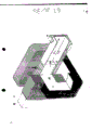
Figure one is the critical piece rough package drawing that shows device;
Figure two is vertical section schematic diagrames of forming two assembly of elements in four unit, operating room;
Figure three is the compound schematic diagrames in several cross sections;
Figure four is end views of expression combustion system part parts;
Figure five is perspective views of a kind of form of magnetohydrodynamic generation passage among the embodiment;
Figure six is air distributing device schematic diagrames and in order to the layout plan of the pumping magnetohydrodynamic electric machine unit that replaces mechanical pumping unit in the operating room;
Figure seven is from the available total power curve in a pair of main chamber;
Figure eight is local skiagraphs of a kind of form of lower end, main chamber.
The Magnetohydrodynamic(MHD) generator of present embodiment as conductor fluid, uses inert gas as the heating power working fluid with liquid metal.Magnetohydrodynamic(MHD) generator is made up of with 1b and 1c two couples of columniform 1a of main chamber of a cover and 1d, and each of its main chamber is communicated with borrowing power channel 78 in the lower end.By this power channel 78 circulation of certain amount of fluid metal is arranged in every pair of main chamber.These four main chambers are placed in the combustion chamber 2 of fuel burner 18 and air inlet 16.2 exhaust is to be finished by the smoke pipe 5 that connects each top, main chamber and bottom from the combustion chamber.The top of each main chamber has top cover 8 to be connected to discharge duct 9.Discharge duct is connected to the air preheater 10 of combustion chamber.This air preheater has at interval, and 14 , And are placed with a series of air duct 13 between the air import and export of preheater.By blower fan 12 air is delivered to preheater, the air after being preheated is delivered to air inlet of combustion chamber 16 through admission line 15.Under the situation of present embodiment, what fuel was used is liquid form, and it is supplied with through filter 21 and heater 22 backs from fuel tank.The gas that discharge heater and combustion chamber 2 has heat exchange relationship.Should be noted that: these fuel burner 18 easy whats substitute or change, be adapted to using gases and (or) solid particle fuel.On the other hand, this combustion chamber can be replaced by the heat exchanger or the suchlike energy of the other energy such as solar collecting device, underground heat gathering-device or nuclear heating.
Each of the 1a of main chamber, 1b, 1c and 1d is connected to heat exchanger 31a, 31b, 31c and 31d respectively, and this device has the fine wire grid of being made by Heat Conduction Material.Being communicated with respectively by separately discharge pipe 24a, 24b, 24c and 24d and input pipe 23a, 23b, 23c and 23d of the 1a of main chamber, 1b, 1c and 1d and heat exchanger 31a, 31b, 31c and 31d realizes.Discharge pipe 24 is communicated with by splash-back (antisplash barrier) 32 corresponding main chambers with it, and input pipe 23 then links to each other with the injector 33 that is contained in the centre position between bottom, main chamber and the top.Each injector 33 of being made up of the pipe arm of many porous radially communicates with separately input pipe by the center holder.Unidirectional valve 58a, b, c and the d that disposes on discharge pipe 24a, 24b, 24c and 24d guaranteed the one-way flow of coming out from each main chamber respectively.Similarly, unidirectional valve 57a, 57b, 57c and the 57d that disposes on input pipe 23a, 23b, 23c and 23d also guaranteed the one-way flow to each main chamber respectively.
Each 1a of main chamber, 1b, 1c and 1d interrelate with ancillary chamber 42a, 42b, 42c and 42d respectively.Main chamber 1 and ancillary chamber 42 communicate by heat exchanger 31.Auxiliary input pipe 35a, 35b, 35c and 35d are configured in respectively on ancillary chamber 42a, 42b, 42c and 42d and the corresponding heat exchanger 31.Be configured in unidirectional valve 56a, 56b, 56c and 56d on the auxiliary line separately and guaranteed one-way flow from separately heat exchanger 31 to ancillary chamber 42.Auxiliary discharge pipe 34a, 34b, 34c and 34d are configured in respectively between ancillary chamber 42a, 42b, 42c and 42d and the heat exchanger 31.Be placed in unidirectional valve 55a, 55b, 55c and 55d on the corresponding auxiliary line and guaranteed from ancillary chamber 42 to heat exchanger 31 one-way flow.
The fluid of adorning a certain amount of heat exchange 42 li of each ancillary chambers can be the same with the fluid of being adorned in the main chamber, also can be different.Connect below the auxiliary liquid level of input pipe 35 in ancillary chamber 42 and cause this chamber.In addition, auxiliary discharge pipe 34 disposes at the inlet of ancillary chamber 42 and is similar to splash-back set in main chamber 1 32.
Each ancillary chamber 42a, b, c and d interrelate with third level chamber 44a, b, c and d respectively again.Each third level chamber sliding bearing respectively piston 43a, b, c, d, and these pistons can make the volume of third level chamber 44a, 44b, 44c and 44d change respectively.The heat-exchange fluid the same with ancillary chamber is equipped with in each third level chamber 44, link up by means of the pipeline between each ancillary chamber lower end and unidirectional valve 46a, the 46b, 46c and the 46d that are added in the pipeline simultaneously, the latter guarantees the fluid one-way flow from ancillary chamber 42 to corresponding third level chamber 44 respectively.Other pipeline and one-way cock 45a, the 45b, 45c and the 45d that are added in the pipeline link each ancillary chamber 42 and corresponding third level chamber, and these one-way cocks guarantee the one-way flow of the ancillary chamber 42 from third level chamber 44 to correspondence.This pipeline is communicated with such position of the lower end of third level chamber 43 and corresponding ancillary chamber respectively, and this position is that the heat-exchange fluid in ancillary chamber occupies a certain position between minimum and maximum horizontal plane.This pipeline is furnished with shower nozzle 54 in the outlet of ancillary chamber.
Each of ancillary chamber 42 of being furnished with heat-exchange fluid uses the heat-exchanger coil 76 that communicates with cooler 77 to make that heat-exchange fluid is easy to cooling in the ancillary chamber.
Public drive motor 72 drives a pair of bent axles 65 and 66 and make piston 43 reciprocating motions.Bent axle 65 drives piston 43b and the 43a of third level chamber 44b and 44a, and 1b of main chamber in this third level chamber and the every pair of main chamber and of 1a interrelate.Similarly, another bent axle 66 drives another piston 43c and 43d to third level chamber, and in this a pair of third level chamber and the every pair of main chamber another interrelates to main chamber 1.Each differs 180 ° of phase places to relevant main chamber the piston and its of third level chamber, and the piston that drives with bent axle differs 90 ° of phase places to each other.
The working space that space that is not occupied by conductor fluid in main chamber and ancillary chamber 1 and 42 and the free space in heat exchanger 31 have constituted engine jointly.In this space, fill, as helium, as working fluid with inert gas.Conductor fluid is subjected to 44 li influences that piston 43 moves in third level chamber in the lifting of 42 li liquid levels of ancillary chamber, therefore, cause that chilled conductor fluid flow to third level chamber 44 from ancillary chamber 42, send back in the ancillary chamber 42 by shower nozzle simultaneously and go, this shower nozzle is placed on certain position in the middle of the highest and floor level face that the conductor fluid of ancillary chamber occupies.
Be in operation and think in power channel 78, there is not the loss that exists owing to friction or electromagnetic load, think that simultaneously the horizontal plane of a pair of 1a in the main chamber and the conductor fluid in the 1d is in their high and minimum situation separately, shared volume is respectively in their minimum and maximum situation third level chamber 44a and 44d space.Along with third level chamber 44 volumes reduce, heat-exchange fluid enters an ancillary chamber 42a, make working fluid in ancillary chamber 42a to heat exchanger 31a heat release, the fluid here then absorbs heat, pass through the injector 33 of an intake pipeline 23a and a 1a of main chamber then, bubbling ground produces the in fact expansion of isothermal up by the upper area of conductor fluid again.The result that the gas pressure located more than the conductor fluid in the 1a of main chamber increases forces conductor fluid here to enter other main chamber by power channel 78.The mobile working fluid of the 1d of another main chamber that makes of this conductor fluid is able to emit a large amount of heat by its corresponding heat exchanger discharge, is injected into again in the cold conductive liquid of another ancillary chamber 42d simultaneously, and the heat balance is here destroyed.Regulate another ancillary chamber of injection 42d of this working fluid by the motion of the piston 43d of another third level chamber 44d.Till this process will last till when conductor fluid occupies minimum and maximum volume respectively in 1a of its main chamber and 1d.Because the downward stroke of piston 43d, the volume of third level chamber 44d has been compressed, and makes the conductor fluid reverse flow 78 li of power channels.The heat that produces in the combustion chamber will make this back and forth flowing continue, and 78 li so reciprocal mobile results will produce alternating current in generator unit at power channel.
In fact, the load that occurs in 78 li of power channels will cause the flowing of conductor fluid in 1a of main chamber and the 1d, piston 43a and 43d reciprocating motion and corresponding thus separately between ancillary chamber and third level chamber flowing of conductor fluid all lag behind, the about 90 ° time actings that lag behind are maximum, its part is for the engine requirements of one's work, and remainder utilizes with what is outside.
Under isolated and full-power condition, when there was the maximum volume of conductor fluid the main chamber, the gas pressure of the working fluid in the working space of main chamber was not enough to overcoming the resistance that is produced that flows of conductor fluid in power channel 78 or other places.On the other hand, when conductor fluid passed through the mobile centre of the power channel between this main chamber, this gas pressure had far surpassed the pressure that produces needed speed in the time of making conductor fluid pass through power channel 78 again.
Because this cause has been used two pairs of main chambers that interknit.Operation a pair of with another to the phase difference near 90 ° is arranged, thus, when of a pair of main chamber of two centerings when its working space has barometric minimum, the gas pressure in a main chamber of another centering but is a peak.For the beginning that impels a main chamber to descend and circulate, a pair of main chamber and another are to just being necessary to install fluid line between the main chamber.The mobile of working fluid controlled by unidirectional valve for pressure difference 67,68,69 and 70 between the main chamber.When only reaching predetermined pressure reduction between these main chambers, just opens by such valve in (referring to figure six).Valve for pressure difference 67,68,69 and 70 opening pressure can need be adjusted by adjustment cam axle 71 according to the operation of engine.Between every pair of main chamber, be communicated with like this by valve for pressure difference, make the working space in decline circulation time main chamber present predetermined pressure, keep the predetermined pressure of this main chamber to discharge working fluid, this working fluid is caused by row in the main chamber of minimum air pressure and goes, the beginning of this circulation that helps to descend, working fluid mobile guaranteed that conductor fluid is that sinusoidal rule changes by the speed of power channel 78 between every pair of main chamber.
Shown in figure two, power channel 78 interrelates with electromagnet 59, and its magnetic pole is on the both sides of passage.When passing power channel 78, cuts conductor fluid the magnetic field of electromagnet orthogonally.Also have pair of electrodes 60 and 61 to be arranged on the both sides of the free time of the field region internal channel that is produced by solenoid 59.When passing the magnetic field of magnet 59, this conductor fluid produces electromotive force electrode 60 and 61.Such power channel is shown in figure five.This passage can also further segment with dividing plate 62 again, and dividing plate is parallel with the flow direction of conductor fluid with the magnetic field orthotropic of electromagnet.Dividing plate has the coating that insulate with conductor fluid by the material Zhi Cheng And of high permeability.Can be as the needs dividing plate by permanent magnetization.This interrelates by dividing plate limited every path with the contacted pair of electrodes 63 of conductor fluid.Consequently each path just becomes an independent generator unit.Some electrode 63 to being in series than obtaining higher voltage with a pair of large electrode.This higher voltage is that with conductor fluid higher interior resistance to be arranged be cost.In order to reduce this resistance, conducting medium can be cooled off by means of the coolant jacket 64 around passage 78 li of power channels.This coolant jacket places each side of solenoid.Except thermal loss is reduced to the minimum, utilize heat-insulating material that each main chamber 1 and smoke pipe 65 and combustion chamber are separated, with the heat of conductor fluid bottom in the main chamber every firmly.(shown in figure eight).For further reducing thermal loss, the hollow cylinder 81 of finding time among the figure eight is placed on the straight line position of the pipeline that leads to each generator unit chamber.This just is equivalent in the process of whole stroke free reciprocating motion and transmits under the situation of power from a side to the opposing party, to heat from 1 thermometal is transmitted to and is provided with obstacle at the magnetohydrodynamic generation passage one than cold metal in the main chamber.The film of liquid metal is with lubricate.If liquid metal is sodium or lithium, it is in addition preheating of the hot fluid that needs overcoat 64 circulations of flowing through at the very start.If liquid metal is at room temperature meltable NaK mixed liquor, then just there is no need to carry out preheating.Can see from the schematic diagram of figure eight and have the device that the heating power working fluid is injected liquid metal.
If desired, can be used in auxiliary magnetic fluid passage 78a between the ancillary chamber 42 of a pair of main chamber 1 and 78b(referring to figure six) replace third level chamber 44 and corresponding piston thereof, be added to alternating source on the electrode of auxiliary magnetohydrodynamic electric machine, they will play the effect as pump, and conductor fluid is back and forth flowed between ancillary chamber in needed mode.
Above-mentioned embodiment has been avoided the several major issue of the prior art that is present in that relates in above content:
1. one kind is fit to commercial use, and the ac power supply system that only need carry out minimal adjustment can be manufactured comes out.Because use with dividing plate high permeability or the permanent magnetization material of the perpendicular placement of the magnetic line of force is next the magnetohydrodynamic generation passage is separated into many littler unit, therefore, the open circuit voltage of magnetohydrodynamic generation unit is than common height.
And because the reciprocal shell of column (the meltable mixture of lithium, sodium or NaK) of the liquid metal in the main chamber has low mass density, therefore, when being added with the normal pressure difference, working fluid will circulate for 25~30 times with per second, and Chun Wu Zhi And is exceeded.Can easily be elevated to this output on the commercial frequency by regulating, to obtain one 25 volts, three-phase, 50~60 hertz the output of sinusoidal voltage waveform, use transformer be elevated to any required final magnitude of voltage to it so long.
2. the liquid metal in the unit is cooled to the temperature Shang , And higher slightly than its fusing point and keeps a rational low viscosity all the time, this just makes the internal resistance loss of magnetohydrodynamic generation unit reduce.For present one-way type Magnetohydrodynamic(MHD) generator, this selection is inapplicable.Edge effect (as turbulent flow) and wet film loss (Wet ting film Loss) still exist, but the dividing plate with parallel what magnetic field makes mobile laminating the former be reduced to minimum at the adjacent channel place, and the latter is not an important loss source simultaneously.
3. because the speed of gas and flow of liquid is medium, obtains low friction and separation loss , And and also do not have high loss parts resembling in the two-phase device.
4. the bubble slippage is not the loss source.
5. owing to only need a spot of liquid metal, just reduced cost.If sodium is major metal, this point is particularly evident because with regard to volume for regard to the basis, it is the most cheap in all metals.A kind of at room temperature is that the liquid meltable mixture of sodium potassium is selected in cold shell of column, but sodium potassium mixture can be replaced by a kind of suitable nonmetal heat-exchange fluid.This just need provide additional precautionary measures can be brought to heat exchanger and go to guarantee not have anything there.If a kind of nonmetal heat-exchange fluid is used, will lose with of the selection of magnetohydrodynamic electric machine unit so as pump.
6. because the heating power working fluid is a kind of inert gas (often being used because of helium has reasonable thermal conductivity).The loss that effect produced of condensing because working fluid contacts with liquid metal will can not take place.
7. in the first half of its stroke, consume and in its latter half, fully recovered at the energy that quickens the liquid metal shell of column.Because being absorbed in, the momentum of liquid metal help compression work gas process to suffer.In other words, the liquid metal shell of column is made it to stop by air cushion Jian Su And, rather than by the lid of container liquid metal flow stop motion , And is consumed the form of its kinetic energy with heat, if the words damaged do not occur.
8. intake ﹠ exhaust valves have been cancelled, and except some simple control valves, do not have valve and are operated among the hot gas.
9. working fluid is the heat that enters working space or cold when regional, use a control valve device inject liquid metal , And and when leaving above-mentioned zone by from extraction more than the surface of above-mentioned liquid metal.Under keeping near compression of isothermal ground and the condition that expands, this makes the speed of heat being imported into or spreading out of gas reach maximum, makes power output reach maximum simultaneously and has improved efficient.
Equally, during working fluid enters (coil pipe that working fluid has been contained a kind of circulating cooling medium herein cools off), being placed in ducted ball-cock device with transportation conductor fluid metal between what ancillary chamber and the third level chamber makes liquid metal be drawn out of , And from the ancillary chamber bottom and injects between compression period subsequently the working fluid more than the liquid metal surface (but not discharging).This has just promoted the speed of heat exchange, and keeps the condition near isothermal between the compression and the phase of expansion.
10. the gas possibility of oozing out has been eliminated.This be because: if with the magnetohydrodynamic electric machine unit instead the selection of the pump of piston be used, then do not exist lubricant to infiltrate the possibility of working space.If a mechanical pump device is used, comprise that then the mechanical part of the piston 43 that is used to drive cold conductor fluid metal shell of column just need make with lubricator.By mineral oil reservoir lubricate, and liquid metal also can seal between the lid of piston and liquid metal, conductor fluid and external agency is isolated comes.
Oil moves cold heat-exchange fluid the infiltrate piston ring.But this can adjust the way of oil pressure reposition frequently with a small-sized centrifugal piston pump that is operated between piston cap and its back.
11. by use in the nuclear industry Liquid Sodium and potassium as heat-exchange medium known the requirement of encapsulating material, what these requirements neither be complicated.Structure is simple, is made up of a large amount of pipe material.The base what points out that in the primary Calculation of the liquid lithium of 1073 ° of K the heat efficiency is 48%, and the Carnot efficiency when disregarding system loss is 66%, and this is the theoretic maximum likelihood of any hot machine that is operated in the same temperature margin.
It is pointed out that scope of the present invention is not limited within the concrete scope of above-mentioned embodiment.
Claims (15)
1, a kind of reciprocating liquid metal magnetohydrodynamic generator, comprise a pair of main chamber, indoor being equipped with a certain amount ofly is made up of and by the conductor fluid of thermal source heating a kind of liquid metal, the main chamber is linked up by the passage that comprises the magnetohydrodynamic generation unit in its lower end, said thus working fluid is injected in the conductor fluid from the centre position between below the horizontal plane of its lower end and conductor fluid and goes, said working fluid part above water of conductor fluid from the main chamber is discharged, after being equipped with, injects the working fluid that a kind of device is discharged in order to cooling and compression the usefulness of main chamber, it is characterized in that each main chamber leads to the workflow body source of gas separately by heat exchanger, said injection starts from the maximum that horizontal plane at main chamber's conductor fluid approaches it and between the decrement phase at its horizontal plane, said heat exchanger absorbs heat from the working fluid of said discharge, and heating is injected into main chamber's said working fluid before.
2,, it is characterized in that in fact said working fluid be made up of inert gas by claim 1 reciprocating liquid metal magnetohydrodynamic generator.
3,, it is characterized in that said working fluid is made up of helium by the reciprocating liquid metal magnetohydrodynamic generator of claim 2.
4, press the reciprocating liquid metal magnetohydrodynamic generator of claim 1, it is characterized in that the workflow body source that is used for each main chamber is made up of the ancillary chamber that has heat exchanger fluid, there is a kind of device to be provided the volume that is used for changing conducting liquid in ancillary chamber, from the main chamber, injects simultaneously and the discharge working fluid.
5, by the reciprocating liquid metal magnetohydrodynamic generator of claim 4, it is characterized in that being provided with a radiator and be used for from conducting liquid, absorbing heat.
6, press the reciprocating liquid metal magnetohydrodynamic generator of claim 4, it is characterized in that each ancillary chamber leads to a third level chamber, as the transmission of the electric liquid of conduction, there is 180 ° phase difference each third level chamber variable volumeization, and this variation simultaneously and another third level chamber.
7, by the reciprocating liquid metal magnetohydrodynamic generator of claim 6, it is characterized in that said each third level chamber is columnar, indoor slip and supporting hermetically and be used at the indoor reciprocating piston of this third level.
8, press the reciprocating liquid metal magnetohydrodynamic generator of claim 4, it is characterized in that being provided with between the said ancillary chamber passage is transmitted conducting liquid, said passage is equipped with second Magnetohydrodynamic(MHD) generator unit, and its electrode makes the change that produces the conducting liquid volume in ancillary chamber by the power supply of first magnetohydrodynamic generation unit.
9, press the reciprocating liquid metal magnetohydrodynamic generator of claim 1, it is characterized in that two pairs of main chambers that are interconnected make by a series of valve for pressure difference between the space of its horizontal plane of conducting liquid in being higher than the main chamber is communicated with, when in the main chamber, having reached the maximum gas pressure power of being scheduled to thus, working fluid is discharged from, and is introduced in the main chamber of minimum gas pressure.
10,, it is characterized in that the predetermined opening pressure of said valve for pressure difference can change by operating one of them cam according to the operation needs of generator by the reciprocating liquid metal magnetohydrodynamic generator of claim 9.
11, press the reciprocating liquid metal magnetohydrodynamic generator of claim 1, the path that passes through said magnetohydrodynamic generation unit that it is characterized in that it is separated by dividing plate, this dividing plate is parallel with the flow direction of conductor fluid with magnetic field orthotropic, said dividing plate is made by the material of high permeability, require simultaneously it and conductor fluid electric insulation, the electrode of paired Magnetohydrodynamic(MHD) generator separately to be arranged in the space by the formed conductor fluid process of said dividing plate again.
12, by the reciprocating liquid metal magnetohydrodynamic generator of claim 11, it is characterized in that its dividing plate has been permanent magnetization.
13, by the reciprocating liquid metal magnetohydrodynamic generator of claim 11, it is characterized in that being cooled in any side of conductor fluid in the magnetohydrodynamic generation unit of said passage.
14, by the reciprocating liquid metal magnetohydrodynamic generator of claim 13, it is characterized in that the lower end of its main chamber is adiabatic to thermal source.
15,, it is characterized in that overlapping sealing cylinder shape parts each sideslip of the passage of its magnetohydrodynamic generation unit by the reciprocating liquid metal magnetohydrodynamic generator of claim 13.
Applications Claiming Priority (2)
| Application Number | Priority Date | Filing Date | Title |
|---|---|---|---|
| AUPH017885 | 1985-04-17 | ||
| AUPH00178 | 1985-04-17 |
Publications (2)
| Publication Number | Publication Date |
|---|---|
| CN86103390A CN86103390A (en) | 1987-06-17 |
| CN1007486B true CN1007486B (en) | 1990-04-04 |
Family
ID=3771055
Family Applications (1)
| Application Number | Title | Priority Date | Filing Date |
|---|---|---|---|
| CN86103390A Expired CN1007486B (en) | 1985-04-17 | 1986-04-17 | Reciprocating liquid metal magnetohydrodynamic generator |
Country Status (9)
| Country | Link |
|---|---|
| US (1) | US4785209A (en) |
| EP (1) | EP0258247A4 (en) |
| JP (1) | JPS62502652A (en) |
| CN (1) | CN1007486B (en) |
| BR (1) | BR8607100A (en) |
| CA (1) | CA1256481A (en) |
| IN (1) | IN167312B (en) |
| WO (1) | WO1986006225A1 (en) |
| ZA (1) | ZA862833B (en) |
Families Citing this family (17)
| Publication number | Priority date | Publication date | Assignee | Title |
|---|---|---|---|---|
| AU604295B2 (en) * | 1987-01-05 | 1990-12-13 | Garrett Michael Sainsbury | Reciprocating free liquid metal piston stirling cycle linear synchronous generator |
| US5473205A (en) * | 1994-03-24 | 1995-12-05 | Martin Marietta Energy Systems, Inc. | Double-duct liquid metal magnetohydrodynamic engine |
| US5923104A (en) * | 1994-05-05 | 1999-07-13 | Lockheed Martin Energy Research Corporation | Single channel double-duct liquid metal electrical generator using a magnetohydrodynamic device |
| US5685966A (en) * | 1995-10-20 | 1997-11-11 | The United States Of America As Represented By The Secretary Of The Navy | Bubble capture electrode configuration |
| AU7893498A (en) * | 1996-12-26 | 1998-07-31 | Harunori Kishi | Energy converter |
| RU2183899C2 (en) * | 1999-08-24 | 2002-06-20 | Грицкевич Олег Вячеславович | Method and magnetohydrodynamic generator for electrical energy production |
| US7166927B2 (en) * | 2004-01-05 | 2007-01-23 | Scientific Applications & Research Associates, Inc. | Modular liquid-metal magnetohydrodynamic (LMMHD) power generation cell |
| US20080072597A1 (en) * | 2006-09-21 | 2008-03-27 | International Business Machines Corporation | Electrically conductive liquid piston engine |
| US8096118B2 (en) | 2009-01-30 | 2012-01-17 | Williams Jonathan H | Engine for utilizing thermal energy to generate electricity |
| FR3021174A1 (en) * | 2014-05-14 | 2015-11-20 | Vexter Ion | PROCESS FOR TRANSFORMING ENERGY USING COMPRESSED GAS AND LIQUID METAL |
| CN104779229B (en) * | 2015-04-13 | 2017-10-03 | 哈尔滨工程大学 | A kind of chip radiator based on thermoelectric cooling principle |
| FR3040838B1 (en) * | 2015-09-04 | 2017-09-22 | Turbomeca | MAGNETOHYDRODYNAMIC GENERATOR |
| CN105112878B (en) * | 2015-09-10 | 2018-01-12 | 中国科学院电工研究所 | The pure alkali metals injection seeded system of inert gas plasma Magnetohydrodynamic(MHD) generator |
| CN105811734A (en) * | 2016-06-05 | 2016-07-27 | 洛阳文森科技有限公司 | Thermoelectric magnetohydrodynamic pulsation power generator |
| CN109713875B (en) * | 2019-01-25 | 2024-03-26 | 山东大学 | Vertical axis ocean energy liquid metal magnetohydrodynamic power generation device and method |
| CN110439768B (en) * | 2019-06-26 | 2021-09-14 | 中国地质大学(武汉) | Solar groove type heat-collecting type magnetofluid thermomagnetic convection circulation double-power generation system |
| CN111277052A (en) * | 2019-11-13 | 2020-06-12 | 北京纳杰科技有限公司 | Power generation method |
Family Cites Families (12)
| Publication number | Priority date | Publication date | Assignee | Title |
|---|---|---|---|---|
| US3102224A (en) * | 1960-02-17 | 1963-08-27 | Paul Levinger | Magnetohydrodynamic a.c. generator |
| US3185871A (en) * | 1961-07-20 | 1965-05-25 | Jr Albert G Bodine | Alternating current magnetohydrodynamic generator |
| US3286108A (en) * | 1961-12-21 | 1966-11-15 | Litton Systems Inc | Magneto-hydrodynamic generator |
| CH402154A (en) * | 1963-04-16 | 1965-11-15 | Brocher Eric | Process for producing alternating electrical energy and generator for implementing this process |
| DE1488115A1 (en) * | 1964-03-14 | 1969-02-06 | Helmuth Butenuth | Thermal engine |
| US3430081A (en) * | 1964-12-02 | 1969-02-25 | Us Air Force | Mercury vapor for magnetohydrodynamic generators |
| US3376440A (en) * | 1965-09-17 | 1968-04-02 | Atomic Energy Commission Usa | Liquid metal piston mhd generator |
| US3443129A (en) * | 1966-03-17 | 1969-05-06 | Trw Inc | Vapor-liquid cycle mhd power conversion |
| US3453462A (en) * | 1966-07-27 | 1969-07-01 | Nasa | Slug flow magnetohydrodynamic generator |
| US3549915A (en) * | 1968-07-10 | 1970-12-22 | North American Rockwell | Method and apparatus for generating pulse electrical power using a magnetohydrodynamic generator system |
| SU873346A1 (en) * | 1979-02-20 | 1981-10-15 | Научно-производственное объединение "ЭНЕРГИЯ" | Linear ac current generator |
| US4486701A (en) * | 1982-01-25 | 1984-12-04 | Cover John H | Thermal energy conversion |
-
1986
- 1986-04-16 US US07/005,157 patent/US4785209A/en not_active Expired - Fee Related
- 1986-04-16 ZA ZA862833A patent/ZA862833B/en unknown
- 1986-04-16 WO PCT/AU1986/000101 patent/WO1986006225A1/en not_active Application Discontinuation
- 1986-04-16 EP EP19860903115 patent/EP0258247A4/en not_active Withdrawn
- 1986-04-16 BR BR8607100A patent/BR8607100A/en unknown
- 1986-04-16 CA CA000506807A patent/CA1256481A/en not_active Expired
- 1986-04-16 IN IN279/MAS/86A patent/IN167312B/en unknown
- 1986-04-16 JP JP61503010A patent/JPS62502652A/en active Pending
- 1986-04-17 CN CN86103390A patent/CN1007486B/en not_active Expired
Also Published As
| Publication number | Publication date |
|---|---|
| WO1986006225A1 (en) | 1986-10-23 |
| EP0258247A1 (en) | 1988-03-09 |
| ZA862833B (en) | 1986-12-30 |
| JPS62502652A (en) | 1987-10-08 |
| EP0258247A4 (en) | 1988-08-04 |
| CN86103390A (en) | 1987-06-17 |
| IN167312B (en) | 1990-10-06 |
| BR8607100A (en) | 1988-02-09 |
| CA1256481A (en) | 1989-06-27 |
| US4785209A (en) | 1988-11-15 |
Similar Documents
| Publication | Publication Date | Title |
|---|---|---|
| CN1007486B (en) | Reciprocating liquid metal magnetohydrodynamic generator | |
| JP4656840B2 (en) | Free piston device with electric linear drive | |
| US8196402B2 (en) | System and method for electrically-coupled thermal cycle | |
| US20110314805A1 (en) | Heat engine with regenerator and timed gas exchange | |
| JP2008528863A (en) | Heat exchange type power plant | |
| KR20110028429A (en) | A stirling engine | |
| CN103382902B (en) | Integrated type Stirling engine for power generation | |
| CN101839230A (en) | Thermal compressor system | |
| JP2018511284A (en) | A device in a thermal cycle for converting heat into electrical energy | |
| CN103470352A (en) | Recovery device for automobile exhaust waste heat based on Stirling engine | |
| CN203374391U (en) | Generator based on Stirling engine | |
| US5077976A (en) | Stirling engine using hydraulic connecting rod | |
| CN103161605A (en) | Liquid piston Stirling engine | |
| CN1131356A (en) | Liquid working medium hot circulation generating device | |
| CN102374152A (en) | Thermal compressor system | |
| CN109882309A (en) | A kind of waste heat efficient temperature-difference generator | |
| AU588331B2 (en) | Reciprocating liquid metal magnetohydrodynamic generator | |
| CN202181998U (en) | Solar-energy Sterling linear generating set | |
| JPS58141647A (en) | Free piston type stirling generator | |
| CN205977567U (en) | Sun light and heat stirling power generation facility | |
| CN202023652U (en) | Heat burning device for flywheel | |
| CN102377282A (en) | Generator driven by thermal compressor | |
| CN106593824A (en) | Linear heat compressor | |
| CN101710781A (en) | Curie point oscillation power generation method and device | |
| US7805934B1 (en) | Displacer motion control within air engines |
Legal Events
| Date | Code | Title | Description |
|---|---|---|---|
| C06 | Publication | ||
| PB01 | Publication | ||
| C10 | Entry into substantive examination | ||
| SE01 | Entry into force of request for substantive examination | ||
| C13 | Decision | ||
| GR02 | Examined patent application | ||
| C14 | Grant of patent or utility model | ||
| GR01 | Patent grant | ||
| C19 | Lapse of patent right due to non-payment of the annual fee | ||
| CF01 | Termination of patent right due to non-payment of annual fee |