CN100586559C - Catalyst for exhaust gas cleaning - Google Patents
Catalyst for exhaust gas cleaning Download PDFInfo
- Publication number
- CN100586559C CN100586559C CN200480034776A CN200480034776A CN100586559C CN 100586559 C CN100586559 C CN 100586559C CN 200480034776 A CN200480034776 A CN 200480034776A CN 200480034776 A CN200480034776 A CN 200480034776A CN 100586559 C CN100586559 C CN 100586559C
- Authority
- CN
- China
- Prior art keywords
- exhaust gas
- purification catalyst
- gas purification
- zirconium
- temperature
- Prior art date
- Legal status (The legal status is an assumption and is not a legal conclusion. Google has not performed a legal analysis and makes no representation as to the accuracy of the status listed.)
- Expired - Fee Related
Links
- 239000003054 catalyst Substances 0.000 title claims abstract description 258
- 238000004140 cleaning Methods 0.000 title abstract 3
- 229910052726 zirconium Inorganic materials 0.000 claims abstract description 66
- QCWXUUIWCKQGHC-UHFFFAOYSA-N Zirconium Chemical compound [Zr] QCWXUUIWCKQGHC-UHFFFAOYSA-N 0.000 claims abstract description 59
- 229910052751 metal Inorganic materials 0.000 claims abstract description 30
- 239000002131 composite material Substances 0.000 claims abstract description 20
- 229910052783 alkali metal Inorganic materials 0.000 claims abstract description 14
- 150000001340 alkali metals Chemical class 0.000 claims abstract description 14
- 229910052761 rare earth metal Inorganic materials 0.000 claims abstract description 13
- 150000002910 rare earth metals Chemical class 0.000 claims abstract description 13
- 238000000746 purification Methods 0.000 claims description 230
- -1 zirconium organic compound Chemical class 0.000 claims description 86
- 238000000034 method Methods 0.000 claims description 28
- 208000035126 Facies Diseases 0.000 claims description 25
- 238000006460 hydrolysis reaction Methods 0.000 claims description 24
- 230000007062 hydrolysis Effects 0.000 claims description 23
- XLYOFNOQVPJJNP-UHFFFAOYSA-M hydroxide Chemical compound [OH-] XLYOFNOQVPJJNP-UHFFFAOYSA-M 0.000 claims description 21
- YRKCREAYFQTBPV-UHFFFAOYSA-N acetylacetone Chemical compound CC(=O)CC(C)=O YRKCREAYFQTBPV-UHFFFAOYSA-N 0.000 claims description 18
- XLYOFNOQVPJJNP-UHFFFAOYSA-N water Substances O XLYOFNOQVPJJNP-UHFFFAOYSA-N 0.000 claims description 18
- BASFCYQUMIYNBI-UHFFFAOYSA-N platinum Chemical group [Pt] BASFCYQUMIYNBI-UHFFFAOYSA-N 0.000 claims description 15
- 150000002500 ions Chemical class 0.000 claims description 13
- 229910000510 noble metal Inorganic materials 0.000 claims description 13
- 229910052746 lanthanum Inorganic materials 0.000 claims description 12
- FZLIPJUXYLNCLC-UHFFFAOYSA-N lanthanum atom Chemical compound [La] FZLIPJUXYLNCLC-UHFFFAOYSA-N 0.000 claims description 12
- 238000004519 manufacturing process Methods 0.000 claims description 12
- 229910052792 caesium Inorganic materials 0.000 claims description 7
- 229910052697 platinum Inorganic materials 0.000 claims description 7
- 230000008569 process Effects 0.000 claims description 7
- 238000006467 substitution reaction Methods 0.000 claims description 7
- TVFDJXOCXUVLDH-UHFFFAOYSA-N caesium atom Chemical group [Cs] TVFDJXOCXUVLDH-UHFFFAOYSA-N 0.000 claims description 6
- 150000002894 organic compounds Chemical class 0.000 claims description 5
- 125000006606 n-butoxy group Chemical group 0.000 claims description 2
- 239000002184 metal Substances 0.000 abstract description 14
- 229910052784 alkaline earth metal Inorganic materials 0.000 abstract description 11
- 150000001342 alkaline earth metals Chemical class 0.000 abstract description 11
- 238000006073 displacement reaction Methods 0.000 abstract description 4
- 239000013078 crystal Substances 0.000 abstract description 3
- RVTZCBVAJQQJTK-UHFFFAOYSA-N oxygen(2-);zirconium(4+) Chemical compound [O-2].[O-2].[Zr+4] RVTZCBVAJQQJTK-UHFFFAOYSA-N 0.000 abstract description 3
- 229910001928 zirconium oxide Inorganic materials 0.000 abstract description 3
- MWUXSHHQAYIFBG-UHFFFAOYSA-N Nitric oxide Chemical compound O=[N] MWUXSHHQAYIFBG-UHFFFAOYSA-N 0.000 description 493
- 239000007789 gas Substances 0.000 description 275
- 239000000446 fuel Substances 0.000 description 137
- 239000002912 waste gas Substances 0.000 description 85
- 229960003753 nitric oxide Drugs 0.000 description 78
- 238000002485 combustion reaction Methods 0.000 description 73
- 230000009467 reduction Effects 0.000 description 49
- 239000003638 chemical reducing agent Substances 0.000 description 48
- 239000001301 oxygen Substances 0.000 description 44
- 229910052760 oxygen Inorganic materials 0.000 description 44
- QVGXLLKOCUKJST-UHFFFAOYSA-N atomic oxygen Chemical compound [O] QVGXLLKOCUKJST-UHFFFAOYSA-N 0.000 description 41
- NHNBFGGVMKEFGY-UHFFFAOYSA-N Nitrate Chemical compound [O-][N+]([O-])=O NHNBFGGVMKEFGY-UHFFFAOYSA-N 0.000 description 30
- IJGRMHOSHXDMSA-UHFFFAOYSA-N Atomic nitrogen Chemical compound N#N IJGRMHOSHXDMSA-UHFFFAOYSA-N 0.000 description 21
- 239000008346 aqueous phase Substances 0.000 description 16
- 150000004703 alkoxides Chemical class 0.000 description 15
- 239000000203 mixture Substances 0.000 description 15
- 239000004094 surface-active agent Substances 0.000 description 14
- 230000006835 compression Effects 0.000 description 13
- 238000007906 compression Methods 0.000 description 13
- 150000002902 organometallic compounds Chemical class 0.000 description 13
- 238000001816 cooling Methods 0.000 description 11
- 239000004530 micro-emulsion Substances 0.000 description 11
- 239000000047 product Substances 0.000 description 11
- 238000000354 decomposition reaction Methods 0.000 description 10
- 229910052757 nitrogen Inorganic materials 0.000 description 10
- SLODBEHWNYQCRC-UHFFFAOYSA-N [La+3].[O-2].[Zr+4] Chemical compound [La+3].[O-2].[Zr+4] SLODBEHWNYQCRC-UHFFFAOYSA-N 0.000 description 9
- 230000001186 cumulative effect Effects 0.000 description 9
- UGFAIRIUMAVXCW-UHFFFAOYSA-N Carbon monoxide Chemical compound [O+]#[C-] UGFAIRIUMAVXCW-UHFFFAOYSA-N 0.000 description 8
- 229910002091 carbon monoxide Inorganic materials 0.000 description 8
- 238000006243 chemical reaction Methods 0.000 description 8
- 238000007254 oxidation reaction Methods 0.000 description 8
- 238000010521 absorption reaction Methods 0.000 description 7
- 239000012298 atmosphere Substances 0.000 description 7
- 229910021645 metal ion Inorganic materials 0.000 description 7
- 238000012545 processing Methods 0.000 description 7
- PNEYBMLMFCGWSK-UHFFFAOYSA-N Alumina Chemical compound [O-2].[O-2].[O-2].[Al+3].[Al+3] PNEYBMLMFCGWSK-UHFFFAOYSA-N 0.000 description 6
- UHOVQNZJYSORNB-UHFFFAOYSA-N Benzene Chemical compound C1=CC=CC=C1 UHOVQNZJYSORNB-UHFFFAOYSA-N 0.000 description 6
- 230000009102 absorption Effects 0.000 description 6
- 230000003647 oxidation Effects 0.000 description 6
- 230000000630 rising effect Effects 0.000 description 6
- CSCPPACGZOOCGX-UHFFFAOYSA-N Acetone Chemical compound CC(C)=O CSCPPACGZOOCGX-UHFFFAOYSA-N 0.000 description 5
- KDLHZDBZIXYQEI-UHFFFAOYSA-N Palladium Chemical compound [Pd] KDLHZDBZIXYQEI-UHFFFAOYSA-N 0.000 description 5
- 239000002202 Polyethylene glycol Substances 0.000 description 5
- 239000011358 absorbing material Substances 0.000 description 5
- 239000003245 coal Substances 0.000 description 5
- 230000007547 defect Effects 0.000 description 5
- 238000010586 diagram Methods 0.000 description 5
- 229930195733 hydrocarbon Natural products 0.000 description 5
- 150000002430 hydrocarbons Chemical class 0.000 description 5
- 239000000463 material Substances 0.000 description 5
- 229920001223 polyethylene glycol Polymers 0.000 description 5
- 239000000779 smoke Substances 0.000 description 5
- 239000004215 Carbon black (E152) Substances 0.000 description 4
- CURLTUGMZLYLDI-UHFFFAOYSA-N Carbon dioxide Chemical compound O=C=O CURLTUGMZLYLDI-UHFFFAOYSA-N 0.000 description 4
- MCMNRKCIXSYSNV-UHFFFAOYSA-N Zirconium dioxide Chemical compound O=[Zr]=O MCMNRKCIXSYSNV-UHFFFAOYSA-N 0.000 description 4
- 238000000975 co-precipitation Methods 0.000 description 4
- 238000010304 firing Methods 0.000 description 4
- ZSIAUFGUXNUGDI-UHFFFAOYSA-N hexan-1-ol Chemical compound CCCCCCO ZSIAUFGUXNUGDI-UHFFFAOYSA-N 0.000 description 4
- 230000007246 mechanism Effects 0.000 description 4
- 239000003595 mist Substances 0.000 description 4
- 239000003960 organic solvent Substances 0.000 description 4
- 230000002000 scavenging effect Effects 0.000 description 4
- 238000003756 stirring Methods 0.000 description 4
- 239000007762 w/o emulsion Substances 0.000 description 4
- LFQSCWFLJHTTHZ-UHFFFAOYSA-N Ethanol Chemical compound CCO LFQSCWFLJHTTHZ-UHFFFAOYSA-N 0.000 description 3
- 230000015572 biosynthetic process Effects 0.000 description 3
- 238000004364 calculation method Methods 0.000 description 3
- 239000003795 chemical substances by application Substances 0.000 description 3
- 238000002474 experimental method Methods 0.000 description 3
- 239000012467 final product Substances 0.000 description 3
- 229910044991 metal oxide Inorganic materials 0.000 description 3
- 150000004706 metal oxides Chemical class 0.000 description 3
- 239000012071 phase Substances 0.000 description 3
- 238000011084 recovery Methods 0.000 description 3
- 239000010948 rhodium Substances 0.000 description 3
- 239000000243 solution Substances 0.000 description 3
- 239000007921 spray Substances 0.000 description 3
- 238000003860 storage Methods 0.000 description 3
- XDTMQSROBMDMFD-UHFFFAOYSA-N Cyclohexane Chemical compound C1CCCCC1 XDTMQSROBMDMFD-UHFFFAOYSA-N 0.000 description 2
- RTZKZFJDLAIYFH-UHFFFAOYSA-N Diethyl ether Chemical compound CCOCC RTZKZFJDLAIYFH-UHFFFAOYSA-N 0.000 description 2
- MYMOFIZGZYHOMD-UHFFFAOYSA-N Dioxygen Chemical compound O=O MYMOFIZGZYHOMD-UHFFFAOYSA-N 0.000 description 2
- 229910002651 NO3 Inorganic materials 0.000 description 2
- 229920003171 Poly (ethylene oxide) Polymers 0.000 description 2
- 239000002250 absorbent Substances 0.000 description 2
- 238000009825 accumulation Methods 0.000 description 2
- 230000009471 action Effects 0.000 description 2
- 239000003945 anionic surfactant Substances 0.000 description 2
- 239000001569 carbon dioxide Substances 0.000 description 2
- 229910002092 carbon dioxide Inorganic materials 0.000 description 2
- 230000003197 catalytic effect Effects 0.000 description 2
- 125000002091 cationic group Chemical group 0.000 description 2
- 210000004027 cell Anatomy 0.000 description 2
- 238000009841 combustion method Methods 0.000 description 2
- 150000001875 compounds Chemical class 0.000 description 2
- 239000000498 cooling water Substances 0.000 description 2
- 239000003599 detergent Substances 0.000 description 2
- 238000001035 drying Methods 0.000 description 2
- 230000000694 effects Effects 0.000 description 2
- 230000012447 hatching Effects 0.000 description 2
- 238000002347 injection Methods 0.000 description 2
- 239000007924 injection Substances 0.000 description 2
- 150000002576 ketones Chemical class 0.000 description 2
- 238000011068 loading method Methods 0.000 description 2
- 150000004692 metal hydroxides Chemical class 0.000 description 2
- 238000002156 mixing Methods 0.000 description 2
- JCXJVPUVTGWSNB-UHFFFAOYSA-N nitrogen dioxide Inorganic materials O=[N]=O JCXJVPUVTGWSNB-UHFFFAOYSA-N 0.000 description 2
- 229910052763 palladium Inorganic materials 0.000 description 2
- 238000001556 precipitation Methods 0.000 description 2
- 229910052703 rhodium Inorganic materials 0.000 description 2
- MHOVAHRLVXNVSD-UHFFFAOYSA-N rhodium atom Chemical compound [Rh] MHOVAHRLVXNVSD-UHFFFAOYSA-N 0.000 description 2
- 230000001052 transient effect Effects 0.000 description 2
- 238000011144 upstream manufacturing Methods 0.000 description 2
- FDCJDKXCCYFOCV-UHFFFAOYSA-N 1-hexadecoxyhexadecane Chemical compound CCCCCCCCCCCCCCCCOCCCCCCCCCCCCCCCC FDCJDKXCCYFOCV-UHFFFAOYSA-N 0.000 description 1
- MGWGWNFMUOTEHG-UHFFFAOYSA-N 4-(3,5-dimethylphenyl)-1,3-thiazol-2-amine Chemical compound CC1=CC(C)=CC(C=2N=C(N)SC=2)=C1 MGWGWNFMUOTEHG-UHFFFAOYSA-N 0.000 description 1
- QTBSBXVTEAMEQO-UHFFFAOYSA-M Acetate Chemical compound CC([O-])=O QTBSBXVTEAMEQO-UHFFFAOYSA-M 0.000 description 1
- ZOXJGFHDIHLPTG-UHFFFAOYSA-N Boron Chemical compound [B] ZOXJGFHDIHLPTG-UHFFFAOYSA-N 0.000 description 1
- YQEVIZPKEOELNL-UHFFFAOYSA-N CCCCO[Zr] Chemical compound CCCCO[Zr] YQEVIZPKEOELNL-UHFFFAOYSA-N 0.000 description 1
- OYPRJOBELJOOCE-UHFFFAOYSA-N Calcium Chemical compound [Ca] OYPRJOBELJOOCE-UHFFFAOYSA-N 0.000 description 1
- 229910052684 Cerium Inorganic materials 0.000 description 1
- VEXZGXHMUGYJMC-UHFFFAOYSA-M Chloride anion Chemical compound [Cl-] VEXZGXHMUGYJMC-UHFFFAOYSA-M 0.000 description 1
- FBPFZTCFMRRESA-JGWLITMVSA-N D-glucitol Chemical compound OC[C@H](O)[C@@H](O)[C@H](O)[C@H](O)CO FBPFZTCFMRRESA-JGWLITMVSA-N 0.000 description 1
- 229910052692 Dysprosium Inorganic materials 0.000 description 1
- 229910052691 Erbium Inorganic materials 0.000 description 1
- 229910052693 Europium Inorganic materials 0.000 description 1
- 229910001111 Fine metal Inorganic materials 0.000 description 1
- 229910052688 Gadolinium Inorganic materials 0.000 description 1
- GYHNNYVSQQEPJS-UHFFFAOYSA-N Gallium Chemical compound [Ga] GYHNNYVSQQEPJS-UHFFFAOYSA-N 0.000 description 1
- 240000004859 Gamochaeta purpurea Species 0.000 description 1
- 229910052689 Holmium Inorganic materials 0.000 description 1
- DGAQECJNVWCQMB-PUAWFVPOSA-M Ilexoside XXIX Chemical compound C[C@@H]1CC[C@@]2(CC[C@@]3(C(=CC[C@H]4[C@]3(CC[C@@H]5[C@@]4(CC[C@@H](C5(C)C)OS(=O)(=O)[O-])C)C)[C@@H]2[C@]1(C)O)C)C(=O)O[C@H]6[C@@H]([C@H]([C@@H]([C@H](O6)CO)O)O)O.[Na+] DGAQECJNVWCQMB-PUAWFVPOSA-M 0.000 description 1
- JVTAAEKCZFNVCJ-UHFFFAOYSA-M Lactate Chemical compound CC(O)C([O-])=O JVTAAEKCZFNVCJ-UHFFFAOYSA-M 0.000 description 1
- WHXSMMKQMYFTQS-UHFFFAOYSA-N Lithium Chemical compound [Li] WHXSMMKQMYFTQS-UHFFFAOYSA-N 0.000 description 1
- 229910052765 Lutetium Inorganic materials 0.000 description 1
- FYYHWMGAXLPEAU-UHFFFAOYSA-N Magnesium Chemical compound [Mg] FYYHWMGAXLPEAU-UHFFFAOYSA-N 0.000 description 1
- 229910052779 Neodymium Inorganic materials 0.000 description 1
- ZLMJMSJWJFRBEC-UHFFFAOYSA-N Potassium Chemical compound [K] ZLMJMSJWJFRBEC-UHFFFAOYSA-N 0.000 description 1
- 229910052773 Promethium Inorganic materials 0.000 description 1
- 229910052772 Samarium Inorganic materials 0.000 description 1
- 229910052775 Thulium Inorganic materials 0.000 description 1
- 238000002441 X-ray diffraction Methods 0.000 description 1
- 229910052769 Ytterbium Inorganic materials 0.000 description 1
- 230000002745 absorbent Effects 0.000 description 1
- 150000001298 alcohols Chemical class 0.000 description 1
- 150000005215 alkyl ethers Chemical class 0.000 description 1
- 229910052782 aluminium Inorganic materials 0.000 description 1
- 239000004411 aluminium Substances 0.000 description 1
- XAGFODPZIPBFFR-UHFFFAOYSA-N aluminium Chemical compound [Al] XAGFODPZIPBFFR-UHFFFAOYSA-N 0.000 description 1
- 150000001412 amines Chemical class 0.000 description 1
- 235000011114 ammonium hydroxide Nutrition 0.000 description 1
- GETQZCLCWQTVFV-UHFFFAOYSA-N anhydrous trimethylamine Natural products CN(C)C GETQZCLCWQTVFV-UHFFFAOYSA-N 0.000 description 1
- 239000007864 aqueous solution Substances 0.000 description 1
- 229910052788 barium Inorganic materials 0.000 description 1
- DSAJWYNOEDNPEQ-UHFFFAOYSA-N barium atom Chemical compound [Ba] DSAJWYNOEDNPEQ-UHFFFAOYSA-N 0.000 description 1
- 239000002585 base Substances 0.000 description 1
- 230000008901 benefit Effects 0.000 description 1
- 229910052790 beryllium Inorganic materials 0.000 description 1
- ATBAMAFKBVZNFJ-UHFFFAOYSA-N beryllium atom Chemical compound [Be] ATBAMAFKBVZNFJ-UHFFFAOYSA-N 0.000 description 1
- 230000002457 bidirectional effect Effects 0.000 description 1
- 229910052796 boron Inorganic materials 0.000 description 1
- 150000001663 caesium Chemical class 0.000 description 1
- 229910052791 calcium Inorganic materials 0.000 description 1
- 239000011575 calcium Substances 0.000 description 1
- 229910052799 carbon Inorganic materials 0.000 description 1
- 239000000969 carrier Substances 0.000 description 1
- 230000035568 catharsis Effects 0.000 description 1
- 210000003850 cellular structure Anatomy 0.000 description 1
- GWXLDORMOJMVQZ-UHFFFAOYSA-N cerium Chemical compound [Ce] GWXLDORMOJMVQZ-UHFFFAOYSA-N 0.000 description 1
- RLGQACBPNDBWTB-UHFFFAOYSA-N cetyltrimethylammonium ion Chemical compound CCCCCCCCCCCCCCCC[N+](C)(C)C RLGQACBPNDBWTB-UHFFFAOYSA-N 0.000 description 1
- 238000005660 chlorination reaction Methods 0.000 description 1
- 229910052878 cordierite Inorganic materials 0.000 description 1
- 150000001934 cyclohexanes Chemical class 0.000 description 1
- JSKIRARMQDRGJZ-UHFFFAOYSA-N dimagnesium dioxido-bis[(1-oxido-3-oxo-2,4,6,8,9-pentaoxa-1,3-disila-5,7-dialuminabicyclo[3.3.1]nonan-7-yl)oxy]silane Chemical compound [Mg++].[Mg++].[O-][Si]([O-])(O[Al]1O[Al]2O[Si](=O)O[Si]([O-])(O1)O2)O[Al]1O[Al]2O[Si](=O)O[Si]([O-])(O1)O2 JSKIRARMQDRGJZ-UHFFFAOYSA-N 0.000 description 1
- 238000007599 discharging Methods 0.000 description 1
- 239000012153 distilled water Substances 0.000 description 1
- KBQHZAAAGSGFKK-UHFFFAOYSA-N dysprosium atom Chemical compound [Dy] KBQHZAAAGSGFKK-UHFFFAOYSA-N 0.000 description 1
- 239000000839 emulsion Substances 0.000 description 1
- 238000005516 engineering process Methods 0.000 description 1
- UYAHIZSMUZPPFV-UHFFFAOYSA-N erbium Chemical compound [Er] UYAHIZSMUZPPFV-UHFFFAOYSA-N 0.000 description 1
- 150000002170 ethers Chemical class 0.000 description 1
- OGPBJKLSAFTDLK-UHFFFAOYSA-N europium atom Chemical compound [Eu] OGPBJKLSAFTDLK-UHFFFAOYSA-N 0.000 description 1
- 229910052730 francium Inorganic materials 0.000 description 1
- KLMCZVJOEAUDNE-UHFFFAOYSA-N francium atom Chemical compound [Fr] KLMCZVJOEAUDNE-UHFFFAOYSA-N 0.000 description 1
- 238000007710 freezing Methods 0.000 description 1
- 230000008014 freezing Effects 0.000 description 1
- 239000002828 fuel tank Substances 0.000 description 1
- UIWYJDYFSGRHKR-UHFFFAOYSA-N gadolinium atom Chemical compound [Gd] UIWYJDYFSGRHKR-UHFFFAOYSA-N 0.000 description 1
- 229910052733 gallium Inorganic materials 0.000 description 1
- 238000007429 general method Methods 0.000 description 1
- KJZYNXUDTRRSPN-UHFFFAOYSA-N holmium atom Chemical compound [Ho] KJZYNXUDTRRSPN-UHFFFAOYSA-N 0.000 description 1
- 229910052738 indium Inorganic materials 0.000 description 1
- APFVFJFRJDLVQX-UHFFFAOYSA-N indium atom Chemical compound [In] APFVFJFRJDLVQX-UHFFFAOYSA-N 0.000 description 1
- 230000001535 kindling effect Effects 0.000 description 1
- FYDKNKUEBJQCCN-UHFFFAOYSA-N lanthanum(3+);trinitrate Chemical compound [La+3].[O-][N+]([O-])=O.[O-][N+]([O-])=O.[O-][N+]([O-])=O FYDKNKUEBJQCCN-UHFFFAOYSA-N 0.000 description 1
- XQBXQQNSKADUDV-UHFFFAOYSA-N lanthanum;nitric acid Chemical compound [La].O[N+]([O-])=O XQBXQQNSKADUDV-UHFFFAOYSA-N 0.000 description 1
- 239000007788 liquid Substances 0.000 description 1
- 229910052744 lithium Inorganic materials 0.000 description 1
- OHSVLFRHMCKCQY-UHFFFAOYSA-N lutetium atom Chemical compound [Lu] OHSVLFRHMCKCQY-UHFFFAOYSA-N 0.000 description 1
- 229910052749 magnesium Inorganic materials 0.000 description 1
- 239000011777 magnesium Substances 0.000 description 1
- 235000013372 meat Nutrition 0.000 description 1
- 229910000000 metal hydroxide Inorganic materials 0.000 description 1
- 150000002739 metals Chemical class 0.000 description 1
- 239000000693 micelle Substances 0.000 description 1
- 239000000178 monomer Substances 0.000 description 1
- QEFYFXOXNSNQGX-UHFFFAOYSA-N neodymium atom Chemical compound [Nd] QEFYFXOXNSNQGX-UHFFFAOYSA-N 0.000 description 1
- ZPIRTVJRHUMMOI-UHFFFAOYSA-N octoxybenzene Chemical compound CCCCCCCCOC1=CC=CC=C1 ZPIRTVJRHUMMOI-UHFFFAOYSA-N 0.000 description 1
- 229920002114 octoxynol-9 Polymers 0.000 description 1
- 238000005457 optimization Methods 0.000 description 1
- 150000003891 oxalate salts Chemical class 0.000 description 1
- 239000002245 particle Substances 0.000 description 1
- 230000002093 peripheral effect Effects 0.000 description 1
- 230000005501 phase interface Effects 0.000 description 1
- 239000003495 polar organic solvent Substances 0.000 description 1
- 239000011148 porous material Substances 0.000 description 1
- 229910052700 potassium Inorganic materials 0.000 description 1
- 239000011591 potassium Substances 0.000 description 1
- VQMWBBYLQSCNPO-UHFFFAOYSA-N promethium atom Chemical compound [Pm] VQMWBBYLQSCNPO-UHFFFAOYSA-N 0.000 description 1
- 229910052701 rubidium Inorganic materials 0.000 description 1
- IGLNJRXAVVLDKE-UHFFFAOYSA-N rubidium atom Chemical compound [Rb] IGLNJRXAVVLDKE-UHFFFAOYSA-N 0.000 description 1
- 150000003839 salts Chemical class 0.000 description 1
- KZUNJOHGWZRPMI-UHFFFAOYSA-N samarium atom Chemical compound [Sm] KZUNJOHGWZRPMI-UHFFFAOYSA-N 0.000 description 1
- 229910052706 scandium Inorganic materials 0.000 description 1
- SIXSYDAISGFNSX-UHFFFAOYSA-N scandium atom Chemical compound [Sc] SIXSYDAISGFNSX-UHFFFAOYSA-N 0.000 description 1
- 239000013049 sediment Substances 0.000 description 1
- 238000000926 separation method Methods 0.000 description 1
- 229910052708 sodium Inorganic materials 0.000 description 1
- 239000011734 sodium Substances 0.000 description 1
- 239000007787 solid Substances 0.000 description 1
- 239000006104 solid solution Substances 0.000 description 1
- 239000002904 solvent Substances 0.000 description 1
- 229910052712 strontium Inorganic materials 0.000 description 1
- CIOAGBVUUVVLOB-UHFFFAOYSA-N strontium atom Chemical compound [Sr] CIOAGBVUUVVLOB-UHFFFAOYSA-N 0.000 description 1
- 239000000758 substrate Substances 0.000 description 1
- 230000002459 sustained effect Effects 0.000 description 1
- 229910052716 thallium Inorganic materials 0.000 description 1
- BKVIYDNLLOSFOA-UHFFFAOYSA-N thallium Chemical compound [Tl] BKVIYDNLLOSFOA-UHFFFAOYSA-N 0.000 description 1
- NAWDYIZEMPQZHO-UHFFFAOYSA-N ytterbium Chemical compound [Yb] NAWDYIZEMPQZHO-UHFFFAOYSA-N 0.000 description 1
- 229910052727 yttrium Inorganic materials 0.000 description 1
- VWQVUPCCIRVNHF-UHFFFAOYSA-N yttrium atom Chemical compound [Y] VWQVUPCCIRVNHF-UHFFFAOYSA-N 0.000 description 1
Images


Classifications
-
- B—PERFORMING OPERATIONS; TRANSPORTING
- B01—PHYSICAL OR CHEMICAL PROCESSES OR APPARATUS IN GENERAL
- B01D—SEPARATION
- B01D53/00—Separation of gases or vapours; Recovering vapours of volatile solvents from gases; Chemical or biological purification of waste gases, e.g. engine exhaust gases, smoke, fumes, flue gases, aerosols
- B01D53/34—Chemical or biological purification of waste gases
- B01D53/92—Chemical or biological purification of waste gases of engine exhaust gases
- B01D53/94—Chemical or biological purification of waste gases of engine exhaust gases by catalytic processes
- B01D53/9445—Simultaneously removing carbon monoxide, hydrocarbons or nitrogen oxides making use of three-way catalysts [TWC] or four-way-catalysts [FWC]
- B01D53/945—Simultaneously removing carbon monoxide, hydrocarbons or nitrogen oxides making use of three-way catalysts [TWC] or four-way-catalysts [FWC] characterised by a specific catalyst
-
- B—PERFORMING OPERATIONS; TRANSPORTING
- B01—PHYSICAL OR CHEMICAL PROCESSES OR APPARATUS IN GENERAL
- B01J—CHEMICAL OR PHYSICAL PROCESSES, e.g. CATALYSIS OR COLLOID CHEMISTRY; THEIR RELEVANT APPARATUS
- B01J23/00—Catalysts comprising metals or metal oxides or hydroxides, not provided for in group B01J21/00
- B01J23/002—Mixed oxides other than spinels, e.g. perovskite
-
- B—PERFORMING OPERATIONS; TRANSPORTING
- B01—PHYSICAL OR CHEMICAL PROCESSES OR APPARATUS IN GENERAL
- B01J—CHEMICAL OR PHYSICAL PROCESSES, e.g. CATALYSIS OR COLLOID CHEMISTRY; THEIR RELEVANT APPARATUS
- B01J23/00—Catalysts comprising metals or metal oxides or hydroxides, not provided for in group B01J21/00
- B01J23/38—Catalysts comprising metals or metal oxides or hydroxides, not provided for in group B01J21/00 of noble metals
- B01J23/54—Catalysts comprising metals or metal oxides or hydroxides, not provided for in group B01J21/00 of noble metals combined with metals, oxides or hydroxides provided for in groups B01J23/02 - B01J23/36
- B01J23/56—Platinum group metals
- B01J23/58—Platinum group metals with alkali- or alkaline earth metals
-
- B—PERFORMING OPERATIONS; TRANSPORTING
- B01—PHYSICAL OR CHEMICAL PROCESSES OR APPARATUS IN GENERAL
- B01J—CHEMICAL OR PHYSICAL PROCESSES, e.g. CATALYSIS OR COLLOID CHEMISTRY; THEIR RELEVANT APPARATUS
- B01J23/00—Catalysts comprising metals or metal oxides or hydroxides, not provided for in group B01J21/00
- B01J23/38—Catalysts comprising metals or metal oxides or hydroxides, not provided for in group B01J21/00 of noble metals
- B01J23/54—Catalysts comprising metals or metal oxides or hydroxides, not provided for in group B01J21/00 of noble metals combined with metals, oxides or hydroxides provided for in groups B01J23/02 - B01J23/36
- B01J23/56—Platinum group metals
- B01J23/63—Platinum group metals with rare earths or actinides
-
- B—PERFORMING OPERATIONS; TRANSPORTING
- B01—PHYSICAL OR CHEMICAL PROCESSES OR APPARATUS IN GENERAL
- B01J—CHEMICAL OR PHYSICAL PROCESSES, e.g. CATALYSIS OR COLLOID CHEMISTRY; THEIR RELEVANT APPARATUS
- B01J2523/00—Constitutive chemical elements of heterogeneous catalysts
-
- Y—GENERAL TAGGING OF NEW TECHNOLOGICAL DEVELOPMENTS; GENERAL TAGGING OF CROSS-SECTIONAL TECHNOLOGIES SPANNING OVER SEVERAL SECTIONS OF THE IPC; TECHNICAL SUBJECTS COVERED BY FORMER USPC CROSS-REFERENCE ART COLLECTIONS [XRACs] AND DIGESTS
- Y02—TECHNOLOGIES OR APPLICATIONS FOR MITIGATION OR ADAPTATION AGAINST CLIMATE CHANGE
- Y02T—CLIMATE CHANGE MITIGATION TECHNOLOGIES RELATED TO TRANSPORTATION
- Y02T10/00—Road transport of goods or passengers
- Y02T10/10—Internal combustion engine [ICE] based vehicles
- Y02T10/12—Improving ICE efficiencies
Landscapes
- Chemical & Material Sciences (AREA)
- Engineering & Computer Science (AREA)
- Materials Engineering (AREA)
- Chemical Kinetics & Catalysis (AREA)
- Organic Chemistry (AREA)
- Health & Medical Sciences (AREA)
- Combustion & Propulsion (AREA)
- Biomedical Technology (AREA)
- Environmental & Geological Engineering (AREA)
- Analytical Chemistry (AREA)
- General Chemical & Material Sciences (AREA)
- Oil, Petroleum & Natural Gas (AREA)
- Exhaust Gas Treatment By Means Of Catalyst (AREA)
- Catalysts (AREA)
- Exhaust Gas After Treatment (AREA)
Abstract
A catalyst for exhaust gas cleaning which has cleaning ability even at high temperatures. This catalyst comprises a crystalline composite zirconium oxide and, deposited thereon, an alkali metal and anoble metal, wherein part of the zirconium of the composite zirconium oxide has been displaced by at least one element selected from the group consisting of alkaline earth metals, rare earth metals, and Group IIIB elements and the elongation of the crystal lattice due to this element displacement is an approximately theoretical value.
Description
Technical field
The present invention relates to a kind of exhaust gas purification catalyst that is used to purify the engine exhaust gas of automobile etc.
Background technology
Usually, from the waste gas that internal combustion engines such as engine for automobile are discharged, contain hydrocarbon (hereinafter referred to as HC), carbon monoxide (CO), oxynitrides (NO
x) wait material (emission).In order to reduce the discharge rate of these materials, except the burning condition optimization of the air-fuel ratio that makes emission etc., the general method of utilizing exhaust gas purification catalyst to remove the material that contains in the waste gas of also using.
As this exhaust gas purification catalyst, generally have in porous matter metal oxide carriers such as aluminium oxide and to carry the so-called three-way catalyst of having held platinum (Pt), rhodium (Rh), palladium noble metals such as (Pd).Be well known that, this three-way catalyst oxidation CO and HC, and have NO
xBe reduced into N
2Ability.
On the other hand, in recent years,, suppress the carbon dioxide (CO that discharges from internal combustion engines such as engine for automobile from the viewpoint of earth environment protection
2) generation become problem, as its countermeasure, developed the Weak mixture engine that in oxygen excess (lean mixture body) atmosphere, carries out lean burn.In this Weak mixture engine, reduced the use amount of fuel, consequently can suppress CO as burnt gas
2Generation.
To this, three-way catalyst in the past is, when air-fuel ratio is chemically correct fuel (stoichiometric proportion), and the HC in the waste gas, CO, NO
xCarry out oxidation/reduction simultaneously, when above-mentioned lean combustion in the oxygen excess atmosphere of waste gas, can oxidation removal HC and CO, but for NO
xReduction remove and not demonstrate sufficient purifying property.
Therefore, developed and a kind ofly burnt under the lean mixture concrete conditions in the establishment of a specific crime of the oxygen excess of being everlasting in lean mixture body burning, at short notice from stoichiometric proportion~dense condition, reduction purifies NO as reducing atmosphere to make waste gas thus
xSystem.And, developed a kind of be suitable for most this system, utilize absorption of N O in lean mixture body atmosphere
x, in stoichiometric proportion~dense mixing atmosphere, emit the NO that has been absorbed
xNO
xThe NO of absorbing material
xAbsorb the reduced form exhaust gas purification catalyst.
This NO
xThe exhaust gas purification catalyst that absorbs reduced form constitutes, and forms the NO that alkali metal, alkaline-earth metal or rare earth metal constitute on the carrier of the porous matter metal oxide of aluminium oxide etc.
xThe layer of absorbing material, and the noble metal catalyst of platinum etc. carried be held on the carrier surface.In this catalyst, when the air-fuel ratio of waste gas is the lean mixture body, the NO that contains in the waste gas
xOxidized by noble metal catalyst, with the situation of nitrate by NO
xAbsorbing material absorbs.Secondly, when the air-fuel ratio of waste gas thickens at short notice, emit in this period and be absorbed in NO
xNO in the absorbing material
x, and with the reaction of the reproducibility composition of HC or CO and be cleaned, when and then the air-fuel ratio of waste gas being returned the lean mixture body, beginning is to NO
xThe NO of absorbing material
xAbsorb, even also can purify NO expeditiously from the waste gas of Weak mixture engine
x
But, this NO
xThe exhaust gas purification catalyst that absorbs reproducibility has EGT particularly when the high temperature more than 500 ℃, NO
xThe problem that detergent power declines to a great extent.Therefore, motion a kind ofly also have higher NO at high-temperature area
xDetergent power, the exhaust gas purification catalyst that constitutes by perovskite composite oxide.(for example opening the 2002-143684 communique) with reference to the spy
In this exhaust gas purification catalyst, has the NO that the perovskite composite oxides promote
xDirectly decomposition is therefore compared with the past, has higher NO in wider temperature range
xPurifying property, still NO in the time of general 700 ℃
xAbsorption reaches capacity, and can't keep NO when higher temperature
xAnd, under practical condition, can not reach sufficient NO
xPurifying rate.
Therefore, the object of the present invention is to provide a kind of exhaust gas purification catalyst,, utilize the zirconium mixed oxide that in crystalline texture, has element-specific, can reach NO at high temperature thus up to 1000 ℃ as catalyst carrier
xPurify.
Summary of the invention
In order to address the above problem a little, according to first mode of the present invention, a kind of exhaust gas purification catalyst, upload at crystalline zirconium mixed oxide and to hold alkali metal and noble metal, above-mentioned zirconium mixed oxide is selected from least a element substitution part zirconium in alkaline-earth metal, rare earth metal and the IIIB family element, by this element substitution, the extension of lattice roughly becomes theoretical value.
According to second mode, in first mode, the above-mentioned at least a element that is selected from alkaline-earth metal, rare earth metal and the IIIB family element is a benchmark with the total mole number of all metallic elements in the zirconium mixed oxide, has 5~50 moles of %.
According to Third Way, in first mode, a part of zirconium is replaced by lanthanum.
According to cubic formula, in first mode, it is caesium that zirconium mixed oxide is uploaded the above-mentioned alkali metal of holding.
According to the 5th mode, in first mode, it is platinum that zirconium mixed oxide is uploaded the above-mentioned noble metal of holding.
Description of drawings
Fig. 1 is the figure that is used to illustrate the situation of the superpower alkalescence point of finding catalyst of the present invention, Fig. 1 (A) represents zirconic crystalline texture, Fig. 1 (B) represents to have replaced with lanthanum the crystalline texture of zirconic a part of zirconium, the crystalline texture of Fig. 1 (C) expression zirconium mixed oxide of the present invention.
Fig. 2 is the figure that is used to illustrate the manufacturing process of catalyst of the present invention.
Fig. 3 is the overall diagram of spark-ignited internal combustion engine.
Fig. 4 is the figure that is used to illustrate the situation of nitric oxide production absorption and decomposition, Fig. 4 (A) and Fig. 4 (B) are illustrated on the carrier with superpower alkalescence point and have adsorbed nitric oxide production state, the state that the state that Fig. 4 (C) expression nitrogen has decomposed, Fig. 4 (D) expression oxygen have broken away from.
Fig. 5 is the figure of relation of the temperature of the amount of the expression energy that should provide and exhaust gas purification catalyst.
Fig. 6 is the figure of the conversion of the nitric oxide amount in the expression waste gas.
Fig. 7 is the figure of the amount of the energy that provides of expression.
Fig. 8 is the flow chart that provides that is used to control energy.
Fig. 9 is the figure of the enriching control of expression air-fuel ratio.
Figure 10 is expression oxygen concentration and NO
xThe timetable of the variation of concentration.
Figure 11 is the figure of relation of the temperature of the reduction dosage that should supply with of expression and exhaust gas purification catalyst.
Figure 12 is the figure of the enriching control of expression air-fuel ratio.
Figure 13 is the flow chart that is used to control the supply of reducing agent.
Figure 14 is the flow chart that is used to carry out nitrate ion and nitric oxide production reduction processing.
Figure 15 is the figure in expression elapsed time.
Figure 16 is used to control the flow chart that reducing agent is supplied with.
Figure 17 is the overall diagram of another embodiment of expression spark-ignited internal combustion engine.
Figure 18 is used to control the flow chart that reducing agent is supplied with.
Figure 19 is the overall diagram of the another embodiment of expression spark-ignited internal combustion engine.
Figure 20 is the overall diagram of the another embodiment of expression spark-ignited internal combustion engine.
Figure 21 is the overall diagram of expression compression ignition engine.
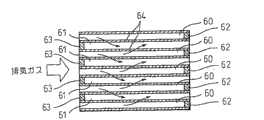
Figure 22 is the figure of expression particulate filter, and Figure 22 (A) is a front view, and Figure 22 (B) is a sectional view.
Figure 23 is the figure of expression smog generation.
Figure 24 (A) is the temperature on average of expression in the combustion chamber and the chart of the relation of crank angle, and Figure 24 (B) is a chart of representing the relation of fuel and temperature on every side and crank angle.
Figure 25 is the figure of expression operation range I, II.
Figure 26 is the figure of expression air-fuel ratio A/F.
Figure 27 is the figure of the variation of expression throttle opening etc.
Figure 28 is the chart of the lattice spacing of expression lanthanum Zirconium oxide.
Figure 29 is the high temperature NO of expression catalyst
xThe chart of absorbent properties.
The specific embodiment
Exhaust gas purification catalyst of the present invention is to upload the catalyst of holding alkali metal and noble metal at crystalline zirconium composite oxides carrier.As this alkali metal, can use lithium, sodium, potassium, rubidium, caesium, francium, as noble metal, can use platinum, palladium, rhodium etc.Preferably, alkali-metal loading amount is 0.05~0.3 mol, and the loading amount of noble metal is 1~5 grams per liter.
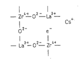
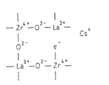
The carrier of exhaust gas purification catalyst of the present invention, shown in Fig. 1 (A), basically have zirconic crystalline texture, the part of the zirconium in this crystalline texture is selected from the zirconium mixed oxide of at least a element substitution in alkaline-earth metal, rare earth metal and the IIIB family element.At this,, can use beryllium, magnesium, calcium, strontium, barium as alkaline-earth metal.As rare earth metal, can use scandium, yttrium, lanthanum, neodymium, promethium, samarium, europium, gadolinium, dysprosium, holmium, erbium, thulium, ytterbium, lutetium.As IIIB family element, can use boron, aluminium, gallium, indium, thallium.Being selected from the content of at least a element in this alkaline-earth metal, rare earth metal and the IIIB family element, is benchmark with the total mole number of all metallic elements in the zirconium mixed oxide, has 5~50 moles of %.
Constituting the zirconic zirconia of crystallinity is 4 valencys, and therefore, it when for example lanthanum is replaced, shown in Fig. 1 (B), is formed the oxygen defect that does not have oxygen by the rare earth metal of the alkaline-earth metal of divalent, 3 valencys or IIIB family element in lattice.
And in these composite oxides, as mentioned above, alkali metal for example caesium is carried and to be held, by this caesium, and shown in Fig. 1 (C), electronics e
-Be provided in the oxygen defect.The oxygen defect that has been provided this electronics demonstrates very strong alkalescence, and therefore, the oxygen defect that has been provided electronics is hereinafter referred to as superpower alkaline point.
In exhaust gas purification catalyst of the present invention, all have crystalline texture shown in Fig. 1 (C) as the zirconium mixed oxide of carrier in integral body, and countless superpower alkaline points distribute evenly on the whole.The catalyst in the past of the carrier of a part of zirconium in the zirconia has been replaced in utilization by lanthanum etc., be to make by the manufacture method of coprecipitation or this composite oxides in the past of alkoxide process, can not fully make lanthanum displacement zirconium, do not have enough superpower alkaline points, and these superpower alkalescence points are evenly distributed.To this, in the carrier of catalyst of the present invention,, can make the lanthanum etc. and zirconium displacement of q.s by using prescriptive procedure, the superpower alkalescence point of q.s is evenly distributed.The extension of the lattice of the Zirconium oxide that the displacement of the lanthanum of this q.s etc. can be caused by element substitution is roughly the reflection of theoretical value this point.
Thus, replace the zirconium mixed oxide that the extension of the lattice that a part of zirconium, this element substitution cause is roughly theoretical value and can utilize following method to make by being selected from least a metal in alkaline-earth metal, rare earth metal and the IIIB family element.
Promptly, by making organic facies after hydrolysis generates the organic compound dissolving of hydroxide of zirconium, contacting as the water that ion is included with second element in will being selected from alkaline-earth metal, rare ± metal and IIIB family element, generate in the process of hydroxide of zirconium at the hydrolysis of the zirconium organic compound by its interface, in this product, introduce second element, the complex hydroxide that is fired into (predecessor) obtains the composite oxides of the zirconium and second element.
At this, the organic compound that hydrolysis generates the hydroxide of zirconium is known, can use wherein any one in the present invention.For example, can list zirconium alkoxide, acetylacetone,2,4-pentanedione zirconium complex.
Zirconium Zr (OR)
4Hydrolysis also be known, can be expressed as: Zr (OR) in form
4+ 4H
2O → Zr (OH)
4+ 4ROH, secondly, Zr (OH)
4→ ZrO
2+ 2H
2O.
Acetylacetone,2,4-pentanedione zirconium complex (CH
3COCH
2COCH
3)
4The hydrolysis of Zr also is known, can be expressed as (CH
3COCH
2COCH
3)
4Zr+4ROH → 4CH
3COCH
2C (OH) CH
3+ Zr (OH)
4, secondly, Zr (OH)
4→ ZrO
2+ 2H
2O.
If select appropriate solvent among polar organic solvent, nonpolarity organic solvent etc., then the organo-metallic compound of zirconium alkoxide or acetylacetone,2,4-pentanedione zirconium complex etc. can relatively easily dissolve.As representative examples of organic, the ketone of straight chain alcohol, the acetone etc. such as hydrocarbon, hexanol of cyclohexane, benzene etc. is arranged.As the choice criteria of organic solvent, the size in the zone of other microemulsions of the solubility of tangible forming surfactants (mol ratio of water/surfactant is bigger) etc.
Be well known that when adding water in the organic facies of the organo-metallic compound that has dissolved this hydrolysis generation hydroxide, the hydrolysis of organo-metallic compound begins, and carries out.Usually, in the organic facies of having dissolved organo-metallic compound, add water, and stir, can access metal hydroxides.
And, be well known that, in organic facies (oil phase), form water in oil emulsion, the microemulsion that water is disperseed imperceptibly with surfactant, in this organic facies (oil phase), add organo-metallic compound (organo-metallic compound is dissolved into solution in the organic solvent), and stir, generate fine metal hydroxides or oxide.Though be not limited in this, can consider to become reaction nuclear by many micelles surface that water constituted that surfactant surrounds, perhaps make the particulate of the hydroxide that surfactant generates stable, obtain fine product particle thus.
Be well known that as mentioned above, in hydrolysis, a plurality of water-disintegrable organo-metallic compounds are dissolved in the organic facies, thus, when it is contacted with water, these a plurality of organo-metallic compound hydrolysis, the hydroxide of a plurality of metals generates simultaneously.
In the present invention, it is characterized in that, a kind of (compound that contains zirconium) in this water-disintegrable organo-metallic compound is present in the organic facies, when this organic facies contacts with water, from the group that alkaline-earth metal, rare earth metal and IIIB family element are constituted, select second metallic element, and the 3rd later metallic element is not to be present in the organic facies as in the past, but exists as ion at aqueous phase.
It is existed as ion at aqueous phase, can use water-soluble metal salt, particularly, inorganic acid salts such as nitrate, chloride also have acylates such as acetate, lactate, oxalates.The ion of second element that is present in aqueous phase can also be the complex ion that comprises second element except being the monomer ion of metal.The ion of the 3rd later element also is same.
When organic facies is contacted with water, organic zirconate in the organic facies contacts with water, cause hydrolysis thus, generate the hydroxide or the oxide of zirconium, but this moment, according to the present invention, the metal ion that can find to be present in aqueous phase is inhaled in the hydroxide (or oxide) as the zirconium of hydrolysis product.This phenomenon is ignorant in the past.Even do not do special precipitation operation and can be inhaled into reason in the hydroxide yet though fully understand the ion of aqueous phase, but the situation that with the organic zirconate is alkoxide is an example when describing, can be understood as, when alkoxide is hydrolyzed, second metal ion of aqueous phase is induced alkoxide, be hydrolyzed, perhaps the alkoxide small hydroxide that carried out hydrolysis is caught the metal ion of aqueous phase ormal weight, and aggegation forms.
According to the present invention, especially in this new manufacturing method, the ion that is present in second metallic element of aqueous phase is inhaled in the hydroxide that the organic zirconate hydrolysis of the zirconium in the organic facies obtains, the dispersed very equably hydroxide of the zirconium in the hydroxide that can obtain to obtain and second metallic element, can find with in the past alkoxide process, be to exist the situation of a plurality of metal alkoxides to compare in the organic facies, can access the significantly outstanding uniformity.Even under lower firing temperature, the zirconium of the composite oxides after also obtaining burning till and second metallic element are with the desirable composite oxides (solid solution) that mix of atomic level.This is that in the past metal alkoxide method is beyond one's reach.In metal alkoxide method in the past, owing to the kind difference according to metal alkoxide, stability is also different, can only obtain uneven product between first metallic element and second metallic element.
Comparing of the zirconium among the present invention in the used composite oxides and second metallic element can be adjusted according to the ratio of the amount of second metallic element of the amount of the zirconium in the organic facies and aqueous phase.
In the present invention, preferably, reaction system is water in oil emulsion class or microemulsion class.In this case, may be thought of as, the first, the microemulsion diameter is little of number nm~ten number nm, and oil phase-aqueous phase interface is very roomy, and (diameter is to be 8000m under the situation of 10nm
2/ liter about) and the high speed of the hydrolysis rate that causes, the second, water is by a minute shellization, each only contains the metal ion (general about 100) of minute quantity and the effect of the homogenising that causes.
Under this purpose, the diameter of the water of microemulsion is 2~40nm, preferably 2~15nm, more preferably 2~10nm.
The method that forms water in oil emulsion class or microemulsion class is known.As the organic facies medium, can use the materials same such as ketone of straight chain alcohols such as hydrocarbons such as cyclohexane, benzene, hexanol, acetone etc. with above-mentioned organic solvent.The surfactant that uses in this programme can be that multiple actives such as nonionic surface active agent, anionic surfactant, cationic surface active agent are used in combination according to purposes and organic facies (oil phase) composition.
As nonionic surface active agent, can use with the polyoxyethylene nonylplenyl ether class of polyethylene glycol oxide (n=5) nonylplenyl ether as representative, polyethylene glycol oxide (n=10) octyl phenyl ether is the polyoxyethylene octylphenyl ether class of representative, polyethylene glycol oxide (n=7) cetyl ether etc. is that the polyethylene oxide alkyl ethers class surfactant of representative, polyethylene glycol oxide D-sorbite trioleate are the polyethylene glycol oxide sorbose alcohols surfactant of representative etc.
As anionic surfactant, can use two-2-ethylidene hexyl sulfo-sodium succinate etc., cationic surface active agent can use chlorination cetyl trimethyl amine or cetyltrimethylammonium base amine etc.
Preferably, use water in oil emulsion class or microemulsion class, but also can make oil type emulsion class in the water.
In the present invention, under the situation of making the composite oxides of element more than three kinds, make the 3rd later element be present in aqueous phase.This is that the stability between the water-disintegrable organo-metallic compound in the organic facies there are differences, thereby produces uneven product owing to make when having a plurality of water-disintegrable organo-metallic compound in the organic facies.But, though must evenly when uniformity is inessential between zirconium and the 3rd metallic element, also can there be the organo-metallic compound of three elements in zirconium and second metal unit between belonging in the organic facies.
As mentioned above, organic facies is contacted with water and when carrying out hydrolysis, generally generate hydroxide (predecessor).According to the present invention, after the product drying, burn till in a word, make composite oxides.The separation of product, drying means is same gets final product.
Firing condition also can be same ground, firing temperature, burn till atmosphere etc. and select to get final product according to the kind of specific composite oxides.But, in general, can burn till with lower temperature compared with the past.Can be regarded as, because metallic element evenly disperses in advance, therefore, the little energy that makes metallic element spread in solid also is fine.
Fig. 2 is the manufacture method that example has schematically shown above-mentioned zirconium mixed oxide to utilize the synthetic lanthanum Zirconium oxide of microemulsion.With reference to Fig. 2, the aqueous phase of microemulsion ME is dissolved with lanthanum nitrate etc., to wherein adding and mixing the zirconium alkoxide, synthesizes the lanthanum Zirconium oxide thus.That is, in the organic facies of microemulsion, only add a kind of metal alkoxide, i.e. the zirconium alkoxide.Because its stability is variant when having a plurality of metal alkoxide in the organic facies, therefore, can not obtain uniform hydrolysis product when contacting with water with respect to organic facies, can address this problem according to this forwarding method.Therefore, when the composite oxides of synthetic metallic element more than three kinds, three elements is added aqueous phase later on to.
The hydrolysis of water-disintegrable organo-metallic compound is known.As can be seen, according to the present invention, the water-disintegrable organic zirconate in the organic facies is contacted with water, in when reaction of being hydrolyzed, at aqueous phase, when second element existed as ion, second element was inhaled in the hydroxide as the hydrolysis product.This reaction is: second element ion of aqueous phase is by the hydrophilic group electric attraction of surfactant, organic zirconium, is inhaled into simultaneously when compound is hydrolyzed, and becomes the composite oxides that contain second element thus.And as can be seen, because this reaction, second element of zirconium that contains in the organic zirconate and aqueous phase can disperse equably, be blended in hydrolysis product even the composite oxides.
To obtain zirconium mixed oxide like this and use, and by using method same, alkali metal and noble metal carried be held on this carrier, obtain exhaust gas purification catalyst of the present invention as carrier.
That the exhaust gas purification catalyst of the present invention obtain like this carries out for utilizing, purify NO when burning with rare air-fuel ratio
xEffect describe.Fig. 3 represents exhaust gas purification catalyst of the present invention is applied to the situation of spark-ignited internal combustion engine.In addition, the present invention also can be applied to compression ignition engine.
With reference to Fig. 3, the 1st, body of the internal-combustion engine, the 2nd, cylinder block, the 3rd, cylinder cover, the 4th, piston, the 5th, combustion chamber, the 6th, electric-controlled type Fuelinjection nozzle, the 7th, spark plug, the 8th, intake valve, the 9th, air inlet, the 10th, exhaust gas valve, the 11st, exhaust outlet.Air inlet 9 is connected with pressurizer tank 13 by pairing air intake branch 12, and pressurizer tank 13 is connected with air cleaner 15 by admission line 14.In admission line 14, dispose the air throttle 17 that drives by stepping motor 16, also in admission line 14, disposed the suction air capacity sensor 18 that is used to detect the mass flow that sucks air.On the other hand, exhaust outlet 11 is connected with the catalytic converter 21 that is built-in with exhaust gas purification catalyst 20 of the present invention by exhaust manifold 19.
Because electronic control unit 30 is made of digital computer, has by bidirectional bus 31 ROM connected to one another (read-only storage) 32, RAM (random access memory) 33, CPU (microprocessor) 34, input port 35 and delivery outlet 36.The output signal that sucks air capacity sensor 18 and fuel pressure sensor 28 is input to input port 35 by pairing AD converter 37.In addition, connecting the load cell 41 of the proportional output voltage of tread amount L of generation and accelerator pedal 40 on accelerator pedal 40, the output voltage of load cell 41 is input to input port 35 by pairing AD converter 37.Also connecting CKP 42 on the input port 35, for example the bent axle revolution promptly produces the output pulse for moving 30 °.In addition, delivery outlet 36 is connected with Fuelinjection nozzle 6, spark plug 7, the stepping motor 16 that is used to drive air throttle, EGR control valve 23 and petrolift 27 by pairing drive circuit 38.
On the end face of piston 4, be formed with cavity 43, when internal combustion engine hangs down load operation, the 43 interior burner oil F from Fuelinjection nozzle 6 towards cavity.This fuel F is by the diapire face of cavity 43 guiding and towards spark plug 7, thereby forms mist around spark plug 7.Then this mist is lighted by spark plug 7, is carried out to grate firing and burns.This moment, combustion chamber 5 interior average air-fuel ratio thinned out, thereby the air-fuel ratio of waste gas also thins out.
When the internal combustion engine medium load turns round, be divided into suction stroke initial stage and compression travel twice burner oil in latter stage.Fuel by the suction stroke initial stage sprays can form the lean mixture gas that is diffused into whole the combustion chamber 5 in combustion chamber 5 in, the fuel by compression travel latter stage sprays can be at the mist of the kindling material of formation formation on every side of spark plug 7.Average air-fuel ratio in the combustion chamber 5 is still thin at this moment, thereby the air-fuel ratio of waste gas is also thin naturally.
On the other hand, when the internal combustion engine high capacity is turned round,, can in combustion chamber 5, form uniform mist thus at suction stroke initial stage burner oil.At this moment, the air-fuel ratios in the combustion chamber 5 can be any in rare air-fuel ratio, chemically correct fuel or the dense air-fuel ratio.Because internal combustion engine turns round under low load or middle load condition usually, thereby can continue to burn under rare air-fuel ratio state usually.
When under rare air-fuel ratio state, burning, utilize exhaust gas purification catalyst 20 to purify 5 NO that discharge from the combustion chamber
x, but about the NO of this exhaust gas purification catalyst 20
xThough the mechanism of catharsis is still very not clear, the result of Fen Xiing can think to purify NO by following mechanism up to now
x.
That is, when under rare air-fuel ratio state, burning, contain nitric oxide NO and nitrogen dioxide NO in the waste gas
2Deng nitrogen oxide NO
xOxygen O with surplus
2In the case, the most of the nitrogen oxide NO that contains of waste gas
xBe nitric oxide NO, therefore hereinafter be illustrated as the purification mechanism of example to nitric oxide NO.
As mentioned above, the exhaust gas purification catalyst among the present invention 20 has superpower alkaline point.In case there is the superpower alkaline point of this kind, no matter then itself be the temperature of the nitric oxide NO exhaust gas purification catalyst 20 of acidity is that height is that low all can being put by superpower alkalescence attracts, and consequently nitric oxide NO is caught by the superpower alkaline point of exhaust gas purification catalyst 20 with certain form shown in Fig. 4 A or Fig. 4 B.In the case, owing to evenly be covered with numerous superpower alkaline point on the whole carrier of above-mentioned exhaust gas purification catalyst 20, thereby the nitric oxide NO of exhaust gas purification catalyst 20 adsorbable a myriad ofs.
Nitric oxide (NO) promptly produced the oxidation reaction of nitric oxide (NO) decomposition and nitric oxide (NO) by the absorption of superpower alkalescence point.Therefore at first the decomposition of nitric oxide (NO) is illustrated.
As mentioned above, the nitric oxide in the waste gas (NO) be subjected to the superpower alkalescence point on the exhaust gas purification catalyst 20 attraction and by the absorption of superpower alkalescence point and catch.At this moment can provide electronics (e to nitric oxide (NO)
-).As the electronics (e that provides to nitric oxide (NO)
-) time, then the N-O key of nitric oxide (NO) produces and decomposes, and in the case, the temperature of exhaust gas purification catalyst 20 is high more, the easy more fracture of this N-O key.In fact, nitric oxide (NO) is adsorbed onto on the superpower alkalescence point, and this N-O key will soon rupture, and is decomposed into nitrogen (N) and oxygen (O), and at this moment, shown in Fig. 4 (C), oxygen is with oxonium ion (O
-) form continue to remain on the superpower alkalescence point, nitrogen (N) then breaks away from superpower alkalescence point and moves on exhaust gas purification catalyst 20.
The nitrogen (N) that moves on exhaust gas purification catalyst 20 combines the back with other nitrogen (N) of being put the nitrogen (N) of the nitric oxide (NO) that adsorbs by other superpower alkalescence of exhaust gas purification catalyst 20 or move on exhaust gas purification catalyst 20 and generates nitrogen molecular (N
2), break away from exhaust gas purification catalyst 20.Can purify NO like this
x
Yet because nitric oxide (NO) is adsorbed onto on the superpower alkalescence point, this nitric oxide (NO) decomposes soon.Oxygen (O) is with oxonium ion (O
-) form caught by superpower alkalescence point, thereby the superpower alkaline point that is present on the exhaust gas purification catalyst 20 can be gradually by oxonium ion (O
-) bury.As mentioned above, superpower alkalescence point is in case by oxonium ion (O
-) bury, then the nitric oxide in the waste gas (NO) promptly be adsorbed onto superpower alkalescence point on nitric oxide (NO) in nitrogen (N) combine, the result generates N
2O.
Oxidation reaction to the nitric oxide on the exhaust gas purification catalyst 20 (NO) is illustrated below.
When under rare air-fuel ratio state, burning, contain superfluous oxygen (O in the waste gas
2).Therefore, be adsorbed to the nitric oxide (N-O that superpower alkalescence is put
-) by this excess oxygen (O
2) institute's oxidation, and therefore form nitrate ion (NO
3 -).That is, when the oxygen concentration in the waste gas was high, reaction was towards generating nitrate ion (NO
3 -) direction carry out, therefore when under rare air-fuel ratio state, burning, on the superpower alkalescence point of part, generate and keep nitrate ion (NO
3 -).And nitrate ion (NO
3 -) also can pass through nitric oxide (NO) and the oxonium ion (O that constitutes crystal
2-) in conjunction with and generate, in addition, the nitrate ion (NO that is generated
3 -) sometimes also to be adsorbed onto the zirconium (Zr that constitutes crystal
4+) on form remain on the exhaust gas purification catalyst 20.
But this nitrate ion (NO
3 -In case) the i.e. decomposition of temperature rising, become nitric oxide (NO) and discharge.Therefore, the temperature one of exhaust gas purification catalyst 20 raises, and then has nitrate ion (NO on exhaust gas purification catalyst 20 hardly
3 -).Therefore, if there being nitrate ion (NO on the exhaust gas purification catalyst 20 hardly
3 -) time the lower limit temperature of exhaust gas purification catalyst 20 be called fiducial temperature, then this fiducial temperature is by exhaust gas purification catalyst 20 decisions, under the situation of exhaust gas purification catalyst 20 of the present invention, this fiducial temperature is roughly 600 ℃, promptly, when the temperature of exhaust gas purification catalyst 20 is lower than this fiducial temperature, will generate nitrate ion (NO on the exhaust gas purification catalyst 20
3 -), when the temperature of exhaust gas purification catalyst 20 is higher than this fiducial temperature, then there is nitrate ion (NO hardly on the exhaust gas purification catalyst 20
3 -).
On the other hand, when under rare air-fuel ratio state, burning, carry the excess oxygen (O that the metal of the cerium (Ce) be held on the exhaust gas purification catalyst 20 and so on is contained in the waste gas
2) oxidation (Ce
2O
3+ 1/2O
2→ 2CeO
2), thereby oxygen can be stored on the exhaust gas purification catalyst 20.Because the oxidation stability of this storage has entered within the brilliant structure, even thereby the temperature of exhaust gas purification catalyst 20 rise, the oxygen of this storage also can not break away from from exhaust gas purification catalyst 20.
In sum, when under rare air-fuel ratio state, burning and the temperature of exhaust gas purification catalyst 20 when being higher than fiducial temperature, keeping oxonium ion (O on the superpower alkalescence point on the exhaust gas purification catalyst 20
-) or still undecomposed nitric oxide (NO), in addition, on exhaust gas purification catalyst 20, also keeping stored oxygen.But this moment, on exhaust gas purification catalyst 20, there is nitrate ion (NO hardly
3 -).
With respect to this,, on the superpower alkalescence point on the exhaust gas purification catalyst 20, still keeping oxonium ion (O even under rare air-fuel ratio state, burn and the temperature of exhaust gas purification catalyst 20 when being lower than fiducial temperature
-) or still undecomposed nitric oxide (NO), in addition, also keeping stored oxygen on the exhaust gas purification catalyst 20.But this moment, on exhaust gas purification catalyst 20, generated a large amount of nitrate ion (NO
3 -).
That is, in other words, when the temperature of exhaust gas purification catalyst 20 was lower than fiducial temperature, the nitric oxide in the waste gas (NO) became nitrate ion (NO on exhaust gas purification catalyst 20
3 -), therefore, though at this moment on exhaust gas purification catalyst 20, there is a large amount of nitrate ion (NO
3 -), still remain on the oxonium ion (O on the exhaust gas purification catalyst 20
-) less relatively.
In contrast, when the temperature of exhaust gas purification catalyst 20 is lower than fiducial temperature, even if generate nitrate ion (NO
3 -) also can decompose, thereby have nitrate ion (NO hardly on the exhaust gas purification catalyst 20. at once
3 -).In addition, owing to nitric oxide (NO) decomposition on the superpower alkalescence point that at this moment is adsorbed onto exhaust gas purification catalyst 20 is active, thereby put the oxonium ion (O that catches by superpower alkalescence
-) amount increase gradually.
Below to the NO of exhaust gas purification catalyst 20
xThe recovery processing procedure of purifying property is illustrated.The temperature of handling along with exhaust gas purification catalyst 20 owing to this recovery changes, thereby the situation that at first temperature of exhaust gas purification catalyst 20 is higher than fiducial temperature is illustrated.
When burning with rare air-fuel ratio state and the temperature of exhaust gas purification catalyst 20 when being higher than fiducial temperature, as mentioned above, on the superpower alkalescence point of exhaust gas purification catalyst 20, can keep the oxonium ion (O that is decomposed
-).If therefore sustained combustion under rare air-fuel ratio state, then the superpower alkaline point of exhaust gas purification catalyst 20 will be gradually by oxonium ion (O
-) bury, the number of the superpower alkalescence point of nitric oxide (NO) reduces gradually like this.NO consequently
xPurifying rate descend gradually.
At this moment, if make the oxonium ion (O that remains on the superpower alkalescence point
-) break away from, promptly remove the oxonium ion (O that remains on the superpower alkalescence point
-), then exhaust gas purification catalyst 20 will become shown in Fig. 4 (D) provides electronics (e to oxygen defect
-) primitive form, can obtain very high NO like this
xPurifying rate.
But from Fig. 4 (C) as can be known, superpower alkalescence point electrically be between the positive metal ion, thereby the electrical oxonium ion (O for bearing
-) be easy to remain between these metal ions.But because this oxonium ion (O
-) and metal ion between adhesion very weak, thereby oxonium ion (O
-) be in utmost point unsure state.Therefore, if will remain on a part of oxonium ion (O in the oxonium ion on the superpower alkalescence point
-) remove from superpower alkalescence point, then be subjected to exciting of this scavenging action, remain on all the other the oxonium ion (O on the superpower alkalescence point
-) also can be removed in the lump.But can not remove the oxygen that is stored on the exhaust gas purification catalyst 20 this moment.
As mentioned above, though excite following remaining oxonium ion (O that removes in the lump for scavenging action at the partial oxygen ion
-) mechanism do not understand that still but the energy that is discharged can think to utilize the partial oxygen ion that is eliminated to form stable oxygen molecule the time is with remaining oxonium ion (O
-) dispose in the lump.In fact, proved by experiment, by the oxonium ion (O that will remain on the exhaust gas purification catalyst 20 is provided to exhaust gas purification catalyst 20
-) remove required energy from exhaust gas purification catalyst 20, thereby the partial oxygen ion that will remain on the exhaust gas purification catalyst 20 is removed from exhaust gas purification catalyst 20, then excites all the other oxonium ion (O that will remain on down on the exhaust gas purification catalyst 20 in this scavenging action
-) dispose from exhaust gas purification catalyst 20 in the lump.In a single day and provide this energy, then promote the decomposition of the nitric oxide (NO) on the superpower alkalescence point, thereby also can from the nitric oxide (NO) of absorption, decompose the oxonium ion (O of coming out
-) remove.
That is, in order to remove all oxonium ion (O that remain on the exhaust gas purification catalyst 20
-), do not remove all oxonium ion (O owing to do not need to provide
-) required energy, remove all oxonium ion (O and only need provide
-) in a part of oxonium ion (O
-) required energy gets final product, thereby advantage is, can reduce to be used to remove oxonium ion (O
-) energy.
In addition, as the energy that should provide various energy are arranged.For example, then can remove the oxonium ion (O that remains on the exhaust gas purification catalyst 20 if improve the temperature of waste gas or the temperature of exhaust gas purification catalyst 20
-).Therefore, as available energy, can use heat energy.
The temperature of exhaust gas purification catalyst 20 is high more, remains on the oxonium ion (O on the exhaust gas purification catalyst 20
-) easy more disengaging.Thereby as shown in Figure 5, with a part of oxonium ion (O that remains on the exhaust gas purification catalyst 20
-) remove required ENERGY E from exhaust gas purification catalyst 20, along with the temperature T C of exhaust gas purification catalyst 20 raises and reduces.
As mentioned above, when the temperature of exhaust gas purification catalyst 20 was higher than fiducial temperature, if burn away under rare air-fuel ratio state, then the superpower alkalescence point on the exhaust gas purification catalyst 20 can be gradually by oxonium ion (O
-) bury, so the quantity of the adsorbable superpower alkalescence point of nitric oxide (NO) can reduce gradually.Consequently, NO
xPurifying rate descend gradually.Therefore, periodically provide energy to exhaust gas purification catalyst 20, so as at exhaust gas purification catalyst 20 by oxonium ion (O
-) will remain on the oxonium ion (O on the exhaust gas purification catalyst 20 before burying
-) dispose from exhaust gas purification catalyst 20.
In the case, can be at regular intervals or the aggregate-value of the rotating speed of internal combustion engine when whenever surpassing setting value, or the operating range of vehicle provides energy when whenever surpassing certain distance.In addition, in the case, can raise along with the temperature of exhaust gas purification catalyst 20 and strengthen after exhaust gas purification catalyst 20 improves energy to the next time interval that provides between energy.
In addition, also can extrapolate the oxonium ion (O that remains on the exhaust gas purification catalyst 20
-) and the total amount of nitric oxide (NO), energy when surpassing set amount, this reckoning total amount is provided.That is, the nitric oxide that comprises in the waste gas (NO) is with original form or the oxonium ion (O after decomposing
-) form remain on the exhaust gas purification catalyst 20.Therefore, remain on oxonium ion (O on the exhaust gas purification catalyst 20
-) and the total amount of nitric oxide (NO) be the cumulative amount of nitric oxide (NO) contained in the waste gas.And the amount of contained nitric oxide (NO) depends on the operating condition of internal combustion engine in the waste gas, in Fig. 6,, express the nitric oxide amount Q (NO) that discharges by internal combustion engine in the time per unit of obtaining by experiment with image format as the function of engine load L and internal-combustion engine rotational speed N.
Under the situation of using above-mentioned image, remain on the oxonium ion (O on the exhaust gas purification catalyst 20
-) and the total amount of nitric oxide (NO) can extrapolate according to the aggregate-value of nitric oxide amount Q (NO) shown in Figure 6.Therefore in the present invention, the aggregate-value of nitric oxide amount Q (NO) shown in Figure 6 as the oxonium ion (O that remains on the exhaust gas purification catalyst 20
-) and the reckoning total amount of nitric oxide (NO) use.
Relation between the aggregate-value ∑ Q of Q shown in Figure 6 (NO) when the temperature that Fig. 7 illustrates exhaust gas purification catalyst 20 is higher than fiducial temperature, the temperature T C of exhaust gas purification catalyst 20 and the energy that provided.
As can be seen from Figure 7, as the oxonium ion (O that remains on the exhaust gas purification catalyst 20
-) and the cumulative amount ∑ Q of nitric oxide (NO) energy then is provided when surpassing set amount QX.At this moment can will remain on the oxonium ion (O on the exhaust gas purification catalyst 20
-) dispose.In addition, one provides energy, then promotes to be adsorbed on the decomposition of the nitric oxide (NO) on the exhaust gas purification catalyst 20, the oxonium ion (O after at this moment decomposing
-) also can be eliminated.In addition as mentioned above, because the temperature of exhaust gas purification catalyst 20 is high more, oxonium ion (O when energy is provided
-) easy more being eliminated, therefore as the oxonium ion (O that remains on the exhaust gas purification catalyst 20
-) the identical situation of quantity under, the temperature of exhaust gas purification catalyst 20 is high more, removes all oxonium ion (O
-) required energy is few more.Therefore as shown in Figure 7, offer the amount of the energy of exhaust gas purification catalyst 20, along with the temperature T C of exhaust gas purification catalyst 20 raises and reduces.
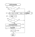
Fig. 8 illustrates the supply control procedure of energy.
As can be seen from Figure 8, at first in step 100, go out nitric oxide amount Q (NO) according to image calculation shown in Figure 6.Then in step 101, calculate cumulative amount ∑ Q by the Q (NO) that on ∑ Q, adds up.Judge in step 102 that then whether cumulative amount ∑ Q surpasses set amount QX, when ∑ Q>QX, enter step 103, the energy that should provide is provided.The processing of energy then is provided in step 104, follows in step 105 ∑ Q zero clearing.
Below the 2nd embodiment is illustrated, wherein, utilization offers in the combustion chamber 5 or the energy that should provide is provided the reducing agent in the waste gas, under rare air-fuel ratio state, burn, and when exhaust gas purification catalyst 20 temperature are higher than by the fiducial temperature of exhaust gas purification catalyst 20 decisions, removing the oxonium ion (O that remains on the exhaust gas purification catalyst 20 from exhaust gas purification catalyst 20
-) time, by putting in 5 to burning or reducing agent being provided in the waste gas, with the air-fuel ratio in the needle pattern enriching combustion chamber 5 or the air-fuel ratio of waste gas.
In the case, can be by reducing agent be provided, with the air-fuel ratio in the periodicity enriching combustion chamber 5 or the air-fuel ratio of waste gas, for example at regular intervals, or the aggregate-value of the rotating speed of internal combustion engine is when whenever surpassing setting value, or the operating range of vehicle enriching air-fuel ratio when whenever surpassing certain distance.
In addition, also can be in the 2nd embodiment according to the oxonium ion (O that remains on the exhaust gas purification catalyst 20
-) and the accumulative total total amount of nitric oxide (NO) carry out the enriching control of air-fuel ratio.
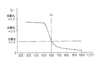
Fig. 9 illustrates the situation when carrying out the control of this kind enriching.
That is, as shown in Figure 9, as the oxonium ion (O that remains on the exhaust gas purification catalyst 20
-) and the total amount ∑ Q that adds up of nitric oxide (NO) when surpassing set amount QX, then in needle pattern enriching combustion chamber 5 or the air-fuel ratio A/F of waste gas, can remove the oxonium ion (O that remains on the exhaust gas purification catalyst 20 like this by providing reducing agent in combustion chamber 5 or in the waste gas
-).
In this embodiment, used the fuel of hydrocarbon-containiproducts etc. as reducing agent, in the case, the fuel that works as reducing agent is the fuel meat with respect to the chemically correct fuel surplus.That is, with regard to Fig. 9, the part of representing with hatching that is richer than chemically correct fuel one side represents to reduce dosage Qr.This reducing agent can be provided in the combustion chamber 5 by the emitted dose that increases Fuelinjection nozzle 6, also can offer from the waste gas that discharge combustion chamber 5.
When under rare air-fuel ratio state, burning, and when the temperature of exhaust gas purification catalyst 20 is higher than by the fiducial temperature of exhaust gas purification catalyst 20 decisions, if provide to exhaust gas purification catalyst 20 to make the partial oxygen that remains on the exhaust gas purification catalyst 20 break away from the required reducing agent of exhaust gas purification catalyst 20, then all the other oxygen that remain on the exhaust gas purification catalyst 20 can be disposed from exhaust gas purification catalyst 20.In more detail the phenomenon of this moment is described with reference to Figure 10.
Figure 10 illustrates when the air-fuel ratio A/F of the waste gas of inflow exhaust gas catalyst for clarifying 20 being maintained rare air-fuel ratio following time of state and the variation and the NO of the oxygen concentration (%) from the waste gas that exhaust gas purification catalyst 20 flows out during with the needle pattern enriching
xThe variation of concentration (p.p.m.).
As mentioned above, when by under rare air-fuel ratio state, burning, when the temperature of exhaust gas purification catalyst 20 is higher than fiducial temperature, keeping oxonium ion (O on the exhaust gas purification catalyst 20
-) and nitric oxide (NO), in addition, also keeping stored oxygen on the exhaust gas purification catalyst 20.But on exhaust gas purification catalyst 20, there is nitrate ion (NO hardly
3 -).
If under this state, switch to densely by rare air-fuel ratio, then remain on a part of oxonium ion (O on the exhaust gas purification catalyst 20
-) will break away from superpower alkaline point, at these oxonium ions (O
-) the exciting of disengaging effect under, remaining oxonium ion (O
-) also can break away from the lump.Generally speaking, do not fire oxygen though still contain in the waste gas under the dense situation of air-fuel ratio A/F, do not fire oxygen if ignore this kind, then air-fuel ratio A/F is switched to when dense by rare, if common catalyst, the oxygen concentration of exhaust gases that then flows out from catalyst is zero.
Yet employed exhaust gas purification catalyst 20 among the present invention because air-fuel ratio A/F is switched to when dense by rare, remains on the oxonium ion (O on the exhaust gas purification catalyst 20
-) break away from, thereby this moment the oxygen concentration from the waste gas that exhaust gas purification catalyst 20 flows out as shown in figure 10, the oxonium ion (O that is broken away from
-) influence and non-vanishing.That is, when air-fuel ratio A/F is switched to when dense by rare, though a part of oxonium ion (O that breaks away from
-) be reduced, but the most of oxonium ion (O that breaks away from
-) be not reduced the agent reduction, but with oxygen molecule (O
2) form from exhaust gas purification catalyst 20, discharge, thereby as shown in figure 10, when air-fuel ratio A/F is switched to when dense from rare, the oxygen concentration in the waste gas that flows out from exhaust gas purification catalyst 20 is a certain amount of.Then, because the oxonium ion (O that breaks away from
-) amount along with the time tails off, its oxygen concentration reduces to zero as shown in figure 10 gradually, in case reduce to zero, after air-fuel ratio A/F be in dense air-fuel ratio during in, oxygen concentration maintains above freezing.
On the other hand, when air-fuel ratio A/F is switched to when dense by rare, the part nitric oxide (NO) that remains on the superpower alkalescence point of exhaust gas purification catalyst 20 is decomposed the oxonium ion (O after the decomposition
-) break away from.In addition, remaining nitric oxide this moment (NO) is reduced agent and reduces, and is decomposed into nitrogen and carbon dioxide, in addition, is stored in the oxygen (O in the exhaust gas purification catalyst 20
2 -) also be reduced agent reduction.Thereby as shown in figure 10, air-fuel ratio be in dense air-fuel ratio during in, the NO in the waste gas that from exhaust gas purification catalyst 20, flows out
xConcentration is zero.
As mentioned above, one provide the reducing agent can be with a part of oxonium ion (O
-) remove from exhaust gas purification catalyst 20, under the exciting of this scavenging action, also can be with all the other oxonium ion (O that remain on the exhaust gas purification catalyst 20
-) from exhaust gas purification catalyst 20, remove in the lump.In addition, one provides reducing agent, can will be adsorbed on nitric oxide (NO) reduction on the exhaust gas purification catalyst 20.Thereby we can say that the energy that utilizes the reducing agent generation to provide is extremely desirable.
Figure 11 represents the relation between the temperature T C of the reduction dosage Qr that represents with equivalent proportion and exhaust gas purification catalyst 20, when being used for for the purifying property that recovers exhaust gas purification catalyst 20 the enriching air-fuel ratio.Wherein, when utilizing reducing agent reduction nitric oxide (NO), with the required reduction dosage of nitric oxide (NO) that is generated in reduction is during the air-fuel ratio of air-fuel ratio in the next enriching combustion chamber 5 or waste gas after the air-fuel ratio of air-fuel ratio in the temporary transient enriching combustion chamber 5 or waste gas, the equivalent proportion that is called reducing agent/NO is 1 reduction dosage Qr.In other words, suppose that nitric oxide (NO) in the waste gas is all with nitrate ion (NO
3 -) form when being absorbed by exhaust gas purification catalyst 20, will reduce this absorbed nitrate ion (NO in theory
3 -) the amount Qr of required reducing agent is called the reduction dosage of equivalent proportion=1.
As can be seen from Figure 11, when the temperature T C of exhaust gas purification catalyst 20 was higher than fiducial temperature Ts, the equivalent proportion of reduction dosage was less than 1.0.In other words, when the temperature T C of exhaust gas purification catalyst 20 is higher than fiducial temperature Ts, in order to remove the oxonium ion (O that remains on the exhaust gas purification catalyst 20
-) and in the enriching combustion chamber reduction dosage Qr the during air-fuel ratio of the air-fuel ratio in 5 or waste gas be less than reduction in from the air-fuel ratio of air-fuel ratio in the last time enriching combustion chamber 5 or waste gas to this enriching combustion chamber 5 air-fuel ratio or the air-fuel ratio of waste gas during in the required reduction dosage of nitric oxide (NO) that generated, promptly be less than equivalent proportion and be 1.0 reduction dosage.
In the embodiment that uses exhaust gas purification catalyst of the present invention, can be to purify NO under the high temperature about 1000 ℃ at the temperature T C of exhaust gas purification catalyst 20
x, when the temperature T C at exhaust gas purification catalyst 20 is under the high temperature about 1000 ℃ during the enriching air-fuel ratio, it is the purifying property that the reducing agent of the amount below 1.0 can recover exhaust gas purification catalyst 20 that equivalent proportion is provided.That is, be less than the NO that reducing agent that reduction enters nitric oxide (NO) aequum in the exhaust gas purification catalyst 20 can recover exhaust gas purification catalyst 20 by providing
xPurifying property, thereby can reduce and be used to recover NO
xThe Fuel Consumption of purifying property.
Therefore, as can be seen from Figure 11, the amount Qr of the reducing agent that should provide during the enriching air-fuel ratio, when the temperature T C of exhaust gas purification catalyst 20 is 800 ℃ of left and right sides, only need about 1/3rd of the required reduction dosage of nitric oxide (NO) contained in the waste gas of reduction inflow exhaust gas catalyst for clarifying 20, be that equivalent proportion is about 1/3rd of 1.0 a reduction dosage, when being 900 ℃ of left and right sides, the temperature T C of exhaust gas purification catalyst 20 only need reduce about 1/4th of the contained required reduction dosage of nitric oxide (NO) in the waste gas of inflow exhaust gas catalyst for clarifying 20, when the temperature T C of exhaust gas purification catalyst 20 is 1000 ℃ of left and right sides, only need reduction to flow into about the sixth of the required reduction dosage of nitric oxide (NO) contained in the waste gas that absorbs decomposition catalyst 20.That is, from Fig. 9 and Figure 11 as can be known, in order to remove the oxonium ion (O that remains on the exhaust gas purification catalyst 20
-) and the reduction dosage Qr that provides can raise along with the temperature T C of exhaust gas purification catalyst 20 and reduce.
On the other hand, when the temperature T C of exhaust gas purification catalyst 20 was lower than fiducial temperature Ts, the amount Qr of the reducing agent that should provide during the enriching air-fuel ratio was that equivalent proportion is the reduction dosage more than 1.0 as shown in figure 10.That is, as indicated above, when under rare air-fuel ratio state, burning and the temperature T C of exhaust gas purification catalyst 20 when being lower than fiducial temperature Ts, on the superpower alkalescence point of exhaust gas purification catalyst 20, still keeping oxonium ion (O
-) and nitric oxide (NO), in addition, on exhaust gas purification catalyst 20, still keeping the oxygen that stores.But, at this moment the nitric oxide (NO) in the waste gas becomes nitrate ion (NO on exhaust gas purification catalyst 20
3 -), therefore, a large amount of nitrate ion (NO are arranged on the exhaust gas purification catalyst 20
3 -), and remain on oxonium ion (O on the exhaust gas purification catalyst 20
-) and nitric oxide (NO) seldom.That is, when the temperature T C of exhaust gas purification catalyst 20 was lower than fiducial temperature Ts, the major part in the nitric oxide in the waste gas (NO) was with nitrate ion (NO
3 -) form absorbed by exhaust gas purification catalyst 20, thereby, but the NO in the purifying exhaust air
x
At this moment if enriching air-fuel ratio, the then nitrate ion (NO that exhaust gas purification catalyst 20 can be absorbed
3 -) and nitric oxide (NO) reduction.Yet because the nitrate ion (NO that adopts reducing agent to carry out this moment
3 -) reduction efficiency be not 100%, thereby in order to reduce the nitrate ion (NO that exhaust gas purification catalyst 20 absorbed
3 -) need be than the nitrate ion (NO of reduction exhaust gas purification catalyst 20 absorptions
3 -) and the required reduction dosage of nitric oxide (NO) also want many reducing agents.Thereby as mentioned above, it is reduction dosage more than 1.0 that the reduction dosage Qr that provides during the enriching air-fuel ratio can be set at equivalent proportion.
Even the nitric oxide amount Q (NO) that when the temperature T C of exhaust gas purification catalyst 20 is lower than fiducial temperature Ts, still can add up and go out according to image calculation shown in Figure 6, as shown in figure 12, when this cumulative amount ∑ Q (NO) exceeds allowance MAX, temporary transient enriching air-fuel ratio A/F.Can recover the purifying property of exhaust gas purification catalyst 20 like this.Relatively Figure 12 and Fig. 9 as can be known, the reduction dosage Qr of this moment compare with situation shown in Figure 9 increased many.In addition, can find out also that the reducing agent Qr of this moment does not also rely on the temperature T C of exhaust gas purification catalyst 20.
Figure 13 represents the supply control procedure of reducing agent.
With reference to Figure 13, judge in step 200 at first whether the temperature T C on the exhaust gas purification catalyst 20 is higher than fiducial temperature Ts.When TC>Ts, then enter step 201, remove the oxygen that remains on the exhaust gas purification catalyst 20.Promptly in step 201, go out nitric oxide amount Q (NO) according to image calculation shown in Figure 6.Then in step 203, upward calculate cumulative amount ∑ Q by Q (NO) being added to ∑ Q.Judge in step 204 that then whether cumulative amount ∑ Q surpasses set amount QX, when ∑ Q>QX, then enter step 205, the reduction dosage that should provide is provided.Then in step 206 by providing reducing agent to handle with the enriching air-fuel ratio, then in step 207 with ∑ Q zero clearing.
On the other hand, when in step 200, being judged as TC≤Ts, then enter step 209, carry out the NO reduction and handle, the nitrate ion (NO that is absorbed with reduction exhaust gas purification catalyst 20
3 -) and nitric oxide (NO).This NO reduction is handled as shown in figure 14.With reference to Figure 14, at first in step 210 according to the image shown in Figure 6 nitric oxide amount Q (NO) that adds up, then in step 211, calculate cumulative amount ∑ Q (NO) on the ∑ Q (NO) by Q (NO) is added to.Judge in step 212 that then whether cumulative amount ∑ Q (NO) surpasses allowance (MAX), when ∑ Q (NO)>MAX, enter step 213, the reduction dosage that should provide is provided.Then, carry out the processing of enriching air-fuel ratio, follow in step 215 ∑ Q (NO) zero clearing by in step 214, supplying with reducing agent.
As indicated above, when the temperature T C of exhaust gas purification catalyst 20 is higher than fiducial temperature Ts, the reduction dosage Qr in the time of can be according to the corresponding minimizing enriching of the rising degree air-fuel ratio of the temperature T C of exhaust gas purification catalyst 20.This means, under the constant substantially situation of reduction dosage Qr, can be according to the time interval till the next enriching air-fuel ratio after the corresponding prolongation enriching of the rising degree air-fuel ratio of the temperature T C of exhaust gas purification catalyst 20.
Thereby as shown in figure 15, in the 3rd embodiment that adopts exhaust gas purification catalyst of the present invention, will be in order to remove the oxonium ion (O that remains on the exhaust gas purification catalyst 20
-) and after the air-fuel ratio of air-fuel ratio in the enriching combustion chamber 5 or waste gas the time interval tX of the air-fuel ratio of the air-fuel ratio in the next enriching combustion chamber 5 or waste gas along with the corresponding increase of rising degree of the temperature T C of exhaust gas purification catalyst 20.
Figure 16 represents to be used to carry out the supply control procedure of the reducing agent of the 3rd embodiment.
With reference to Figure 16, judge in step 220 at first whether the temperature T C of exhaust gas purification catalyst 20 is higher than fiducial temperature Ts.When TC>Ts, enter step 221, will be added on the ∑ t to the time Δ t of this cycle of treatment, calculate elapsed time ∑ t thus from cycle of treatment last time.Then in step 222, calculate target elapsed time tX according to Figure 13.Judge in step 223 that then whether elapsed time ∑ t surpasses target elapsed time tX, when ∑ t>tX, enter step 224, the reduction dosage that should provide is provided.The then processing by providing reducing agent to carry out the enriching air-fuel ratio in step 225 is followed in step 226 ∑ t zero clearing.
On the other hand, when in step 220, being judged as TC≤Ts, enter step 208, implement NO reduction shown in Figure 14 and handle.
Figure 17 illustrates the 4th embodiment.As shown in figure 17, in this embodiment, configuration is used for detecting the NO of the waste gas of exhaust gas purification catalyst 20 in the blast pipe 43 that is in exhaust gas purification catalyst 20 downstreams
xThe NO of concentration
xConcentration sensor 44.
Superpower alkalescence at exhaust gas purification catalyst 20 is put as yet not by oxonium ion (O
-) bury during in since waste gas in contained NO
xCaught by exhaust gas purification catalyst 20, thereby contain NO hardly in the waste gas that from exhaust gas purification catalyst 20, flows out
xYet, in case quite a few is arranged by oxonium ion (O in the superpower alkalescence point of exhaust gas purification catalyst 20
-) bury, then do not caught by exhaust gas purification catalyst 20, and the direct NO by exhaust gas purification catalyst 20
xAmount can increase gradually.Thereby in the 4th embodiment, the NO in the waste gas that from exhaust gas purification catalyst 20, flows out
xWhen concentration surpassed permissible value, then being judged as superpower alkalescence point had quite a few own by oxonium ion (O
-) bury, the air-fuel ratio of the waste gas of inflow exhaust gas catalyst for clarifying 20 is thickened by rare with needle pattern.
Figure 18 represents to be used to implement the supply control procedure of the reducing agent of the 4th embodiment.
With reference to Figure 18, at first in step 230, utilize NO
x Concentration sensor 44 detects the NO in the waste gas that flows out from exhaust gas purification catalyst 20
xConcentration De.Then in step 231, judge NO
xThe NO that concentration sensor 44 is detected
xWhether concentration De is greater than permissible value DX.When De≤DX, finish this cycle of treatment.In contrast, when De>DX, then enter step 232, judge whether the temperature T C of exhaust gas purification catalyst 20 is higher than fiducial temperature Ts.When TC>Ts, enter step 233, the reduction dosage that should provide is provided.Follow in step 234 by providing reducing agent to carry out the processing of enriching air-fuel ratio.This moment, the amount of the reducing agent that provides was less than equivalent proportion=1 o'clock.
On the other hand, when in step 232, judging TC≤Ts, then enter step 235, the reduction dosage that should provide is provided.Then, in step 236 by providing reducing agent to carry out the processing of enriching air-fuel ratio.This moment the reducing agent that provides amount more than equivalent proportion=1 o'clock.
Figure 19 illustrates another embodiment.In the present embodiment, shown in dotted line, exhaust gas purification catalyst was held in 50 years on the internal face of combustion chambers such as end face 5 of the internal face of cylinder cover 3 and piston 4, or exhaust gas purification catalyst was held in 51 years on the internal face of exhaust steam passages such as internal face of the internal face of exhaust outlet 11 and exhaust manifold 19.When on the internal face that exhaust gas purification catalyst was held in combustion chamber 5 in 50 years, burning gases or burnt gas in the combustion chamber 5 contact with exhaust gas purification catalyst 50, contained nitrogen oxide in above-mentioned burning gases or the burnt gas, mainly be nitric oxide NO, be decomposed into nitrogen (N) and oxygen (O) after being adsorbed onto on the exhaust gas purification catalyst 50, when on the internal face that exhaust gas purification catalyst 51 is supported at exhaust steam passage, 5 waste gas of discharging contact with exhaust gas purification catalyst 51 from the combustion chamber, are decomposed into nitrogen (N) and oxygen (O) after contained nitric oxide (NO) is adsorbed onto on the exhaust gas purification catalyst 51 in this waste gas.
In the embodiment shown in Figure 20, configuration reducing agent supply valve 52 in the exhaust manifold 19 that is in exhaust gas purification catalyst 20 upstreams when needing the air-fuel ratio of enriching waste gas, provides reducing agent by this reducing agent supply valve 52 to waste gas.
Situation when Figure 21 represents to apply the present invention to compression ignition engine.In Figure 21, represent the formation identical with spark-ignited internal combustion engine shown in Figure 3 with same numeral.In Figure 21, the 1st, body of the internal-combustion engine, the 5th, the combustion chamber of each cylinder, the 6th, be used for the electric-controlled type Fuelinjection nozzle of burner oil in each combustion chamber 5 respectively, 13a is an inlet manifold, the 19th, exhaust manifold.Inlet manifold 13a is connected via the outlet of admission line 14 with the compressor 53a of exhaust-driven turbo-charger exhaust-gas turbo charger 53, and the inlet of compressor 53a is connected with air cleaner 15.Configuration section valve 17 in admission line 14, and around admission line 14, dispose the cooling device 54 that is used to cool off the suction air that in admission line 14, flows.On the other hand, exhaust manifold 19 is connected with the inlet of the exhaust gas turbine 53b of exhaust-driven turbo-charger exhaust-gas turbo charger 53, and the outlet of exhaust gas turbine 53b is connected with the catalytic converter 21 that is built-in with exhaust gas purification catalyst 20.Configuration reducing agent supply valve 55 provides the reducing agent that is made of hydrocarbon and so on for the air-fuel ratio of enriching waste gas in the set portion outlet of exhaust manifold 19.Exhaust manifold 19 and inlet manifold 13a are connected to each other via EGR passage 22, configuration electric-controlled type EGR control valve 23 in EGR passage 22.And configuration is used to cool off the cooling device 24 of the EGR gas that flows in EGR passage 22 around EGR passage 22.In addition, each Fuelinjection nozzle 6 is via fuel feed pipe 25 rail 26 connections together, and the electric-controlled type petrolift 27 variable by discharge rate provides fuel in this common rail 26.
In this compression ignition engine, under rare air-fuel ratio state, continue to burn, when the air-fuel ratio that makes waste gas for the purifying property that recovers exhaust gas purification catalyst 20 during, in waste gas, provide reducing agent by reducing agent supply valve 55 with periodicity needle pattern enriching.
And in this compression ignition engine, when the temperature T C of exhaust gas purification catalyst 20 is higher than fiducial temperature Ts by exhaust gas purification catalyst 20 decision, periodically the amount of the reducing agent that provides be less than reduction from last time provide after the reducing agent this provide reducing agent during the NO of interior inflow exhaust gas catalyst for clarifying 20
xRequired reduction dosage; When the temperature T C of exhaust gas purification catalyst 20 is lower than fiducial temperature Ts by exhaust gas purification catalyst 20 decision, periodically the amount of the reducing agent that provides more than reduction from last time provide after the reducing agent this provide reducing agent during the NO of interior inflow exhaust gas catalyst for clarifying 20
xRequired reduction dosage.
Below embodiment shown in Figure 21 is illustrated, wherein, the configuration particulate filter forms the exhaust gas purification catalyst layer to replace exhaust gas purification catalyst 20 on this particulate filter.
Figure 22 (A) and Figure 22 (B) illustrate the structure of this particulate filter.Figure 22 (A) is the front view of particulate filter, and Figure 22 (B) is the sectional view of particulate filter.Shown in Figure 21 A and Figure 21 B, particulate filter has cellular structure, has a plurality of exhaust steam passages 60,61 that extend parallel to each other.These exhaust steam passages comprise: the waste gas flow pass 61 that waste gas flow channel 60 that downstream is sealed by cock 62 and upstream extremity are sealed by cock 63.The part of band hatching is represented cock 63 among Figure 22 (A).Therefore waste gas flow channel 60 and waste gas flow pass 61 pass through dividing plate 64 alternate configurations of thin-walled each other.In other words, configuration waste gas flow channel 60 and waste gas flow pass 61 make each waste gas flow channel 60 be surrounded by 4 waste gas flow pass 61, and each waste gas flow pass 61 is surrounded by 4 waste gas flow channels 60 equally.
Particulate filter is for example formed by the porous material of cordierite and so on, therefore, shown in arrow among Figure 22 (B), flow into waste gas in the waste gas flow channel 60 dividing plate 64 around passing after, from adjacent waste gas flow pass 61, flow out.In this embodiment, in the peripheral wall surface of each waste gas flow channel 60 and each waste gas flow pass 61, promptly all form the exhaust gas purification catalyst layer on the both side surface of each dividing plate 64 and on the micropore internal face in the dividing plate 64.
In this embodiment, recover the NO of exhaust gas purification catalyst when needs
xDuring purifying property, but the air-fuel ratio of same enriching waste gas.And in this embodiment, particulate contained in the waste gas is caught by particulate filter, can utilize the heat of waste gas that captive particulate is burnt successively.When a large amount of particulates is deposited on the particulate filter, reducing agent then is provided and waste gas is heated up, make the particulate ignition of accumulation thus.
The following describes a kind of low-temperature combustion method, this low-temperature combustion method is applied in compression ignition engine in order to recover the NO of exhaust gas purification catalyst
xWhen purifying property and air-fuel ratio in the enriching combustion chamber.
In compression ignition engine shown in Figure 21, lead (EGR gas flow/(EGR gas flow+suction air capacity)) if increase EGR, then the generating capacity of smog increases gradually and reaches peak value, leads if further improve EGR, and then the generating capacity of smog sharply descends on the contrary.Describe with reference to Figure 23, the EGR when Figure 23 represents that the cooling degree of EGR gas changes lead and smog between relation.And the curve A among Figure 23 is represented powerful cooling EGR gas and the situation when the EGR gas temperature maintained 90 ℃ of left and right sides, the situation the when situation when curve B is represented to utilize small cooling device to cool off EGR gas, curve C are represented not force to cool off EGR gas.
Shown in the curve A of Figure 23, under the situation of brute force cooling EGR gas, lead on 50% position at EGR, the smog generating capacity reaches peak value; At this moment roughly be set in more than 55% as if EGR is led, then produce smog hardly.In addition, shown in the curve B of Figure 23, under the situation of cooling off EGR gas a little, lead at EGR that the smog generating capacity reaches peak value on a little higher than 50% the position; At this moment roughly be set in more than 65% as if EGR is led, then produce smog hardly.In addition, shown in the curve C of Figure 23, under the situation of not forcing cooling EGR gas, leading at EGR is near 55% the position, and the smog generating capacity reaches peak value; Roughly be set in 70% or more as if EGR is led this moment, then produces smog hardly.
As mentioned above, then produce smog more than 55% hardly as if EGR is led to be set at, its reason is, because the heat-absorbing action of EGR gas, fuel during burning and gas temperature on every side are very not high, promptly, carry out low-temperature burning, consequently, hydrocarbon fails to generate coal smoke.
This low-temperature burning has following characteristics: irrelevant with air-fuel ratio, and can suppress smog and produce, and can reduce NO
xGeneration.That is, though when the enriching air-fuel ratio fuel surplus because ignition temperature is controlled at low temperature, thereby superfluous fuel do not produce coal smoke, so can not produce smog.And, at this moment, NO
xGeneration also few.In addition, when average air-fuel ratio is thin, perhaps when air-fuel ratio is chemically correct fuel, though produce a spot of coal smoke along with the rising of ignition temperature, but owing under low-temperature burning, ignition temperature can be controlled at lower temperature, thereby do not produce smog fully, NO
xAlso produce few.
In addition, when carrying out this low-temperature burning, though fuel and gas temperature step-down on every side thereof, the temperature of waste gas but raises.Be explained with reference to Figure 24 (A) and Figure 24 (B).
Average gas temperature T g in the combustion chamber 5 when the solid line of Figure 24 (A) is represented to carry out low-temperature burning and the relation between the crank angle; Average gas temperature T g in the combustion chamber 5 when the dotted line of Figure 24 (A) is represented to carry out normal combustion and the relation between the crank angle.And, the relation between the fuel the when solid line of Figure 24 (B) is represented to carry out low-temperature burning and gas temperature Tf on every side and the crank angle; Relation between fuel when the dotted line of Figure 24 (B) is represented to carry out normal combustion and gas temperature Tf on every side and the crank angle.
Compare when carrying out normal combustion when carrying out low-temperature burning, the EGR gas flow is big, therefore shown in Figure 24 (A), before compression top center, during being compression travel, the average gas temperature T g when the average gas temperature T g the during low-temperature burning represented with solid line is higher than the normal combustion that is represented by dotted lines.And this moment, shown in Figure 24 (B), fuel and gas temperature Tf on every side thereof are identical substantially with average gas temperature T g.
Then take fire near compression top center, when carrying out low-temperature burning in the case, shown in the solid line of Figure 24 (B), because the heat-absorbing action of EGR gas, fuel and gas temperature Tf on every side thereof are very not high.In contrast, under the situation of carrying out normal combustion, owing to have a large amount of oxygen around the fuel, so shown in the dotted line of Figure 24 (B), fuel and gas temperature Tf on every side thereof are high.As mentioned above, it is high when though fuel and gas temperature Tf on every side thereof are than low-temperature burning during normal combustion, but when the temperature that accounts for most remaining gas is lower than low-temperature burning when being normal combustion on the contrary, therefore shown in Figure 24 (A), average gas temperature T g near the compression top center the combustion chamber 5 is when being higher than normal combustion when low-temperature burning.Consequently, shown in Figure 24 (A), the burnt gas temperature in the combustion chamber 5 after burning finishes, when being higher than normal combustion when low-temperature burning, thereby EGT rises when carrying out low-temperature burning.
But, if the torque TQ that requires of internal combustion engine uprises, promptly fuel injection amount increases, and the gas temperature around the fuel during then owing to burning reaches raises, thereby is difficult to carry out low-temperature burning.That is when, low-temperature burning only limits to burn in the less internal combustion engine of the caloric value that produces low load operation.
In Figure 25, it is the operation range of low-temperature burning that area I represents to carry out the 1st burning, and wherein said the 1st burning is the non-active gas amount when the non-active gas amount of combustion chamber 5 reaches peak value more than the coal smoke generation; It is the operation range of normal combustion that area I I represents to carry out the 2nd burning, and wherein said the 2nd burning is the non-active gas amount when the non-active gas amount of combustion chamber is less than the coal smoke generation and reaches peak value.
Figure 26 is illustrated in the target air-fuel ratio A/F when carrying out low-temperature burning among the operation range I, and aperture, the aperture of EGR control valve 23, the EGR that Figure 27 is illustrated in air throttle corresponding with requiring torque TQ when carrying out low-temperature burning among the operation range I 17 leads, air-fuel ratio, injection beginning time θ S, spray concluding time θ E and emitted dose.In addition, in Figure 27, also express the aperture etc. of the air throttle 17 when in operation range II, carrying out normal combustion in the lump.
From Figure 26 and Figure 27 as can be known, when carrying out low-temperature burning in operation range I, EGR can be led and be set in more than 55%, air-fuel ratio A/F can be set at the rare air-fuel ratio about 15.5 to 18.As above-mentioned, when in operation range I, carrying out low-temperature burning, even the enriching air-fuel ratio also produces smog hardly.
As mentioned above, when carrying out low-temperature burning, can enriching empty combustion and produce smog hardly.Therefore, as NO for the recovery exhaust gas purification catalyst
xCatharsis and when needing the enriching air-fuel ratio, can carry out low-temperature burning, thus under the low-temperature burning state enriching air-fuel ratio.
In addition, as mentioned above, when carrying out low-temperature burning, then EGT rises.Thereby, when needing the rising EGT, also can carry out low-temperature burning for the particulate ignition that makes accumulation.
Embodiment
Make surfactant solution in volume is the beaker of 3L, dripping therein is dissolved into the aqueous solution in 140 parts of the distilled water with 0.03 molar nitric acid lanthanum, and stirs modulation microemulsion liquid.Then, dripping is dissolved into solution in 200 parts of the cyclohexanes with 0.12 mole of four n-butoxy zirconium, carries out the hydrolysis of four n-butoxy zirconiums.Generate the sediment of white at once.In order to control the aggegation of precipitation, utilize ammoniacal liquor pH value be adjusted to 8.5 thereafter.Thereafter continuous stirring is 1 hour, carries out the slaking of product.Filtrated stock cleans being deposited in the ethanol of obtaining three times, after a dry evening under 80 ℃ the state, burns till 2 hours with 200 ℃ in air, obtains comprising the composite oxides (lanthanum Zirconium oxide) of lanthanum and zirconium.The mol ratio of the La/Zr of these composite oxides is 1/4.
Measure the lanthanum Zirconium oxide that obtains like this by the X-ray diffraction method, obtain the face interval of (111) face.Its result as shown in figure 28.And in order to compare, Figure 28 has still gone out the corresponding data of the same lanthanum Zirconium oxide of the coprecipitation of previous methods and alkoxide process manufacturing.
In Figure 28, straight line shown in the solid line is to be connected ZrO
2(the La containing ratio is 0) and LaZrO
3.5Straight line between (111) face of theoretical lattice in the composition of (La containing ratio 50%) value at interval, the face in the calculating of each composition (La containing ratio) of expression at interval.What coprecipitation or alkoxide process in the past obtained is the lattice paprmeter shorter than theoretical value, represents that most of La does not replace ZrO
2Lattice.To this, lanthanum Zirconium oxide of the present invention is complete face interval according to theoretical value, La
3+Ion is almost completely replaced ZrO
2Lattice.
Secondly, the lanthanum Zirconium oxide for making among the embodiment 1 utilizes commonsense method to be coated on the monolithic substrate, and makes the platinum of holding 1 weight % its year, and carries and hold with lanthanum with the caesium of molal quantity as alkali metal, obtains exhaust gas purification catalyst of the present invention.And, as a comparison, use the lanthanum Zirconium oxide that obtains by coprecipitation and alkoxide process, and make equally and hold platinum and caesium its year.
High temperature NO for these catalyst
XAbsorbent properties are discussed.Experiment is in 600 ℃ reducing atmosphere behind the reducing catalyst, at NO714ppm+O
23%/N
2Under the balance conducting, cool to 100 ℃, measuring N O from 750 ℃ with 20 ℃/minute speed
XReduced rate.The result as shown in figure 29.
As shown in figure 29, clearly, when utilizing catalyst in the past, NO more than 700 ℃ the time
xHold facility suddenly disappear, with respect to this, when utilizing catalyst of the present invention, even also can keep NO at 1000 ℃ high temperature
x
Claims (9)
1. exhaust gas purification catalyst, upload at crystalline zirconium mixed oxide and to hold alkali metal and noble metal, it is characterized in that, above-mentioned zirconium mixed oxide is selected from least a element substitution part zirconium of the rare earth metal of trivalent, by this element substitution, the extension of lattice roughly becomes theoretical value.
2. exhaust gas purification catalyst as claimed in claim 1, the described at least a element that is selected from the rare earth metal of trivalent is a benchmark with the total mole number of all metallic elements in the zirconium mixed oxide, has 5~50 moles of %.
3. exhaust gas purification catalyst as claimed in claim 1, a part of zirconium is replaced by lanthanum.
4. it is caesium that exhaust gas purification catalyst as claimed in claim 1, zirconium mixed oxide are uploaded the described alkali metal of holding.
5. it is platinum that exhaust gas purification catalyst as claimed in claim 1, zirconium mixed oxide are uploaded the described noble metal of holding.
6. the manufacture method of the described exhaust gas purification catalyst of claim 1, be manufactured on crystalline zirconium mixed oxide and upload the exhaust gas purification catalyst of holding alkali metal and noble metal, it is characterized in that, by making the organic facies after hydrolysis generates the organic compound dissolving of hydroxide of zirconium, contact as the water that ion is included with second element of the rare earth metal that will be selected from trivalent, generate in the process of hydroxide of zirconium at the hydrolysis of the zirconium organic compound by its interface, in this product, introduce second element, the complex hydroxide that is fired into, obtain the composite oxides of the zirconium and second element, and then make and hold alkali metal and noble metal its year.
7. the manufacture method of exhaust gas purification catalyst according to claim 6, described hydrolysis and the organic compound that generates the hydroxide of zirconium are a kind of in selected among zirconium alkoxide, the acetylacetone,2,4-pentanedione zirconium complex.
8. the manufacture method of exhaust gas purification catalyst according to claim 6, described hydrolysis and the organic compound that generates the hydroxide of zirconium is four n-butoxy zirconiums.
9. the manufacture method of exhaust gas purification catalyst according to claim 6, described second element is a lanthanum.
Applications Claiming Priority (2)
| Application Number | Priority Date | Filing Date | Title |
|---|---|---|---|
| JP2003364852A JP4120559B2 (en) | 2003-10-24 | 2003-10-24 | Exhaust gas purification catalyst |
| JP364852/2003 | 2003-10-24 |
Publications (2)
| Publication Number | Publication Date |
|---|---|
| CN1886194A CN1886194A (en) | 2006-12-27 |
| CN100586559C true CN100586559C (en) | 2010-02-03 |
Family
ID=34510134
Family Applications (1)
| Application Number | Title | Priority Date | Filing Date |
|---|---|---|---|
| CN200480034776A Expired - Fee Related CN100586559C (en) | 2003-10-24 | 2004-10-14 | Catalyst for exhaust gas cleaning |
Country Status (5)
| Country | Link |
|---|---|
| US (1) | US20070066479A1 (en) |
| EP (1) | EP1681096B1 (en) |
| JP (1) | JP4120559B2 (en) |
| CN (1) | CN100586559C (en) |
| WO (1) | WO2005039759A1 (en) |
Families Citing this family (8)
| Publication number | Priority date | Publication date | Assignee | Title |
|---|---|---|---|---|
| JP4325648B2 (en) | 2005-10-24 | 2009-09-02 | トヨタ自動車株式会社 | Catalyst carrier and exhaust gas purification catalyst |
| JP4881758B2 (en) * | 2006-04-28 | 2012-02-22 | 日産自動車株式会社 | Exhaust gas purification catalyst and method for producing the same |
| EP1941945B1 (en) | 2007-01-05 | 2012-01-18 | Kabushiki Kaisha Toyota Chuo Kenkyusho | Catalyst for removing particulate matter and method using the same for removing particulate matter |
| US20090264283A1 (en) * | 2008-04-16 | 2009-10-22 | Basf Catalysts Llc | Stabilized Iridium and Ruthenium Catalysts |
| FR2939695B1 (en) | 2008-12-17 | 2011-12-30 | Saint Gobain Ct Recherches | PURIFICATION STRUCTURE INCORPORATING A CATALYSIS SYSTEM SUPPORTED BY A REDUCED ZIRCONY. |
| US8003567B2 (en) * | 2009-08-17 | 2011-08-23 | Honda Motor Co., Ltd. | Nanocomposite support materials |
| US10232352B2 (en) * | 2015-03-20 | 2019-03-19 | Haldor Topsøe A/S | Catalyzed ceramic candle filter and method of cleaning process off- or exhaust gases |
| WO2018035434A1 (en) * | 2016-08-19 | 2018-02-22 | Kohler Co. | System and method for low co emission engine |
Citations (1)
| Publication number | Priority date | Publication date | Assignee | Title |
|---|---|---|---|---|
| JP2003001109A (en) * | 2001-06-26 | 2003-01-07 | Daihatsu Motor Co Ltd | Catalyst for purifying exhaust gas |
Family Cites Families (18)
| Publication number | Priority date | Publication date | Assignee | Title |
|---|---|---|---|---|
| JPH02175602A (en) * | 1988-12-28 | 1990-07-06 | Ricoh Co Ltd | Production of ultrafine particle metal oxide composition and ultrafine particle zirconium oxide composition obtained thereby |
| US5747410A (en) * | 1992-07-03 | 1998-05-05 | Kabushiki Kaisha Riken | Exhaust gas cleaner and method of cleaning exhaust gas |
| JPH06178937A (en) * | 1992-10-15 | 1994-06-28 | Riken Corp | Catalyst for removing nitrogen oxides and method of removing the same |
| JP4098835B2 (en) * | 1993-12-07 | 2008-06-11 | トヨタ自動車株式会社 | Exhaust gas purification catalyst |
| JPH08281106A (en) * | 1995-04-11 | 1996-10-29 | Nissan Motor Co Ltd | Catalyst for purifying exhaust gas and its production |
| JPH0924274A (en) * | 1995-05-09 | 1997-01-28 | Hitachi Ltd | Catalyst and system for purifying exhaust gas |
| JP3498453B2 (en) * | 1995-11-27 | 2004-02-16 | 日産自動車株式会社 | Exhaust gas purification catalyst and method for producing the same |
| JP4053623B2 (en) | 1996-12-27 | 2008-02-27 | 阿南化成株式会社 | Zirconium-cerium composite oxide and method for producing the same |
| JP3466856B2 (en) * | 1997-02-05 | 2003-11-17 | トヨタ自動車株式会社 | Exhaust gas purification catalyst and method for producing the same |
| JP2001170487A (en) * | 1999-12-15 | 2001-06-26 | Toyota Central Res & Dev Lab Inc | Catalyst for purifying exhaust gas and method for purifying exhaust gas |
| US6511642B1 (en) * | 1999-01-12 | 2003-01-28 | Kabushiki Kaisha Toyota Chuo Kenkyusho | Porous material, catalyst, method of producing the porous material and method for purifying exhaust gas |
| EP1172139B1 (en) * | 2000-07-14 | 2006-10-11 | Kabushiki Kaisha Toyota Chuo Kenkyusho | Catalyst for purifying exhaust gas |
| JP3758487B2 (en) * | 2000-09-08 | 2006-03-22 | トヨタ自動車株式会社 | Absorption reduction type NOx purification catalyst |
| US7285259B2 (en) | 2001-05-23 | 2007-10-23 | Ecaps | Sintering resistant catalyst material and a method for the preparation thereof |
| JP4228278B2 (en) * | 2002-03-19 | 2009-02-25 | トヨタ自動車株式会社 | Exhaust gas purification catalyst |
| JP3758601B2 (en) * | 2002-05-15 | 2006-03-22 | トヨタ自動車株式会社 | NOx storage reduction catalyst |
| JP4812233B2 (en) | 2003-02-28 | 2011-11-09 | トヨタ自動車株式会社 | Method for producing composite oxide |
| EP1479651B2 (en) * | 2003-05-21 | 2017-07-19 | Toyota Jidosha Kabushiki Kaisha | Method for production of porous composite oxide |
-
2003
- 2003-10-24 JP JP2003364852A patent/JP4120559B2/en not_active Expired - Fee Related
-
2004
- 2004-10-14 CN CN200480034776A patent/CN100586559C/en not_active Expired - Fee Related
- 2004-10-14 US US10/576,025 patent/US20070066479A1/en not_active Abandoned
- 2004-10-14 EP EP04792725A patent/EP1681096B1/en not_active Expired - Fee Related
- 2004-10-14 WO PCT/JP2004/015575 patent/WO2005039759A1/en active Search and Examination
Patent Citations (1)
| Publication number | Priority date | Publication date | Assignee | Title |
|---|---|---|---|---|
| JP2003001109A (en) * | 2001-06-26 | 2003-01-07 | Daihatsu Motor Co Ltd | Catalyst for purifying exhaust gas |
Also Published As
| Publication number | Publication date |
|---|---|
| US20070066479A1 (en) | 2007-03-22 |
| WO2005039759A1 (en) | 2005-05-06 |
| EP1681096B1 (en) | 2012-11-21 |
| EP1681096A4 (en) | 2010-09-15 |
| JP4120559B2 (en) | 2008-07-16 |
| EP1681096A1 (en) | 2006-07-19 |
| CN1886194A (en) | 2006-12-27 |
| JP2005125254A (en) | 2005-05-19 |
Similar Documents
| Publication | Publication Date | Title |
|---|---|---|
| CN101292077B (en) | Exhaust cleaner for internal combustion engine | |
| CN100398789C (en) | Exhaust gas cleaning method and apparatus thereof | |
| CN100420829C (en) | Exhaust emission purification apparatus of compression ignition type internal combustion engine | |
| RU2480592C1 (en) | Cleaning system of exhaust gas of internal combustion engine | |
| US7375054B2 (en) | Exhaust gas treatment catalyst and exhaust gas treatment method | |
| JP4270224B2 (en) | Exhaust gas purification device for internal combustion engine | |
| CN1676893A (en) | Exhaust gas cleaning device | |
| CN101542085A (en) | Exhaust cleaner for internal combustion engine | |
| CN102859136A (en) | Exhaust gas purification device for internal combustion engine | |
| KR100841427B1 (en) | Exhaust purification system of internal combustion engine | |
| CN101784764B (en) | Exhaust gas purification apparatus for internal combustion engine and method of controlling the same | |
| CN102223951A (en) | Particulate substance removing material, particulate substance removing filter catalyst using particulate substance removing material, and method for regenerating particulate substance removing filter catalyst | |
| KR20020024595A (en) | Exhaust gas cleaning device for internal combustion engines | |
| CN100586559C (en) | Catalyst for exhaust gas cleaning | |
| CN100449123C (en) | Method of purifying exhaust from internal combustion engine and exhaust purification equipment | |
| CN100582454C (en) | Exhaust purifier for internal combustion engine | |
| US11007480B2 (en) | Exhaust gas purification system | |
| JP2003193822A (en) | Exhaust emission control device for internal combustion engine | |
| JP2001336414A (en) | Method for purifying exhaust gas and its apparatus | |
| CN101006252A (en) | Reductant addition in exhaust system comprising nox-absorbent | |
| CN103154454B (en) | Exhaust gas purifying device for internal combustion engine | |
| CN101542086B (en) | Exhaust purification device for internal combustion engine | |
| JP2003049631A (en) | Exhaust emission control device | |
| JP5142086B2 (en) | Exhaust purification system | |
| JP2002364339A (en) | Exhaust emission control device and exhaust emission control method |
Legal Events
| Date | Code | Title | Description |
|---|---|---|---|
| C06 | Publication | ||
| PB01 | Publication | ||
| C10 | Entry into substantive examination | ||
| SE01 | Entry into force of request for substantive examination | ||
| C14 | Grant of patent or utility model | ||
| GR01 | Patent grant | ||
| CF01 | Termination of patent right due to non-payment of annual fee | ||
| CF01 | Termination of patent right due to non-payment of annual fee |
Granted publication date: 20100203 Termination date: 20171014 |