CN100559825C - The method of image processing apparatus and control image processing apparatus - Google Patents
The method of image processing apparatus and control image processing apparatus Download PDFInfo
- Publication number
- CN100559825C CN100559825C CNB200710129780XA CN200710129780A CN100559825C CN 100559825 C CN100559825 C CN 100559825C CN B200710129780X A CNB200710129780X A CN B200710129780XA CN 200710129780 A CN200710129780 A CN 200710129780A CN 100559825 C CN100559825 C CN 100559825C
- Authority
- CN
- China
- Prior art keywords
- paper
- zone
- finger print
- print information
- area ratio
- Prior art date
- Legal status (The legal status is an assumption and is not a legal conclusion. Google has not performed a legal analysis and makes no representation as to the accuracy of the status listed.)
- Expired - Fee Related
Links
Images


Classifications
-
- G—PHYSICS
- G07—CHECKING-DEVICES
- G07D—HANDLING OF COINS OR VALUABLE PAPERS, e.g. TESTING, SORTING BY DENOMINATIONS, COUNTING, DISPENSING, CHANGING OR DEPOSITING
- G07D7/00—Testing specially adapted to determine the identity or genuineness of valuable papers or for segregating those which are unacceptable, e.g. banknotes that are alien to a currency
- G07D7/20—Testing patterns thereon
- G07D7/202—Testing patterns thereon using pattern matching
- G07D7/2033—Matching unique patterns, i.e. patterns that are unique to each individual paper
-
- G—PHYSICS
- G06—COMPUTING; CALCULATING OR COUNTING
- G06V—IMAGE OR VIDEO RECOGNITION OR UNDERSTANDING
- G06V20/00—Scenes; Scene-specific elements
- G06V20/80—Recognising image objects characterised by unique random patterns
-
- G—PHYSICS
- G06—COMPUTING; CALCULATING OR COUNTING
- G06V—IMAGE OR VIDEO RECOGNITION OR UNDERSTANDING
- G06V30/00—Character recognition; Recognising digital ink; Document-oriented image-based pattern recognition
- G06V30/10—Character recognition
- G06V30/14—Image acquisition
- G06V30/1444—Selective acquisition, locating or processing of specific regions, e.g. highlighted text, fiducial marks or predetermined fields
-
- G—PHYSICS
- G06—COMPUTING; CALCULATING OR COUNTING
- G06V—IMAGE OR VIDEO RECOGNITION OR UNDERSTANDING
- G06V30/00—Character recognition; Recognising digital ink; Document-oriented image-based pattern recognition
- G06V30/10—Character recognition
- G06V30/18—Extraction of features or characteristics of the image
- G06V30/18086—Extraction of features or characteristics of the image by performing operations within image blocks or by using histograms
-
- G—PHYSICS
- G06—COMPUTING; CALCULATING OR COUNTING
- G06V—IMAGE OR VIDEO RECOGNITION OR UNDERSTANDING
- G06V30/00—Character recognition; Recognising digital ink; Document-oriented image-based pattern recognition
- G06V30/10—Character recognition
Abstract
The invention discloses the method for a kind of image processing apparatus and control image processing apparatus.It is based on the view data of input, and search wherein is equipped with a little area ratio greater than the second area ratio and less than the zone of first area ratio, and obtains the paper finger print information from the zone of finding by search.
Description
Technical field
The present invention relates to a kind of can the handling of paper finger print information image processing apparatus, method, program and the storage medium of control image processing apparatus of (below be also referred to as the paper fingerprint).
Background technology
Paper is that crossed fiber about 20 to 30 microns forms by having width.Crossed fiber forms random pattern.This random pattern is unique for every paper, is similar to fingerprint.This random pattern on the paper is also referred to as the paper finger print information.
Because the paper finger print information is unique for every paper,, so just can be advantageously used in determining that subsequently paper is ' original paper ' or ' counterfeit ' " by registration " original paper that I provide is the paper with this certain paper finger print information ".Term " counterfeit " comprises " copy of original paper ".
According to opening disclosed technology among the 2004-112644 the Japanese documentation spy, when making original paper, with reference to the mark that appends on the original paper paper, the zone that has a preset distance with this mark as the reference position is defined as the paper finger print information and obtains the zone.And according to disclosed technology in the document, the paper finger print information obtains the zone acquisition from the paper finger print information of regulation.And according to disclosed technology in the document, the paper finger print information is encoded with the generation coded image, and this coded image is printed on the paper of original paper.
And according to the 58th section the description of opening 2005-038389 the Japanese documentation spy, it thinks preferably based on print data, judges the scope that toner in the recording paper etc. is not attached, and sets the paper finger print information and obtain the zone in this scope.
When the paper finger print information obtains the zone according to when the Japanese documentation spy opens that disclosed technology is set among the 2004-112644, all black zone that therefrom can not obtain the paper finger print information might be set to the paper finger print information and obtain the zone.The all black zone that therefrom can not obtain paper finger print information (even or obtained the paper finger print information, also can fail in the time of relatively) might be set to the paper finger print information and obtain the zone and be one problem to be solved is arranged.
When the paper finger print information obtains the zone according to when the Japanese documentation spy opens that disclosed technology is come regulation among the 2005-038389, the whole white zone might be set to the paper finger print information and obtain the zone.The whole white zone might be cut out down and be attached on other a piece of paper by the third party of malice.When this happens, a piece of paper can be identified as original paper in addition.
Summary of the invention
According to an aspect of the present invention, a kind of image processing apparatus is provided, it comprises search unit and acquiring unit, search unit is based on the view data of input, on the paper that will be printed from view data, search wherein is equipped with a little area ratio greater than the second predetermined area ratio and less than the zone of the first predetermined area ratio; Acquiring unit is from as the Search Results of search unit and obtain the paper finger print information from the zone that paper finds.Wherein, the first predetermined area ratio is greater than the second predetermined area ratio.
Further feature of the present invention will clear record in below with reference to the description of the embodiment of accompanying drawing.
Description of drawings
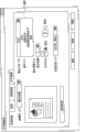
Fig. 1 is the figure that the configured in one piece of image formation system is shown;
Fig. 2 is the external view of the input-output apparatus of image processing system;
Fig. 3 is the figure that the configured in one piece of image processing system is shown;
Fig. 4 is the figure that block data is shown;
Fig. 5 is the block diagram of scanner image processor;
Fig. 6 is the block diagram of printer image processor;
Fig. 7 is the schematic diagram that duplicates screen-picture of operating unit;
Fig. 8 is by the flow chart of paper finger print information acquiring unit in the processing of S1602 execution shown in Figure 16;
Fig. 9 is the flow chart in the processing of S1703 execution shown in Figure 17;
Figure 10 is the flow chart that the paper finger print information obtains the processing that main frame is carried out in the processing during printing;
Figure 11 is the flow chart that obtains the processing that image processing system is carried out in the processing during printing at the paper fingerprint;
Figure 12 obtains the schematic diagram that drives screen-picture in the processing on the main frame at the paper finger print information during printing;
Figure 13 illustrates the figure that the paper finger print information obtains the zone;
Figure 14 determines that the paper finger print information obtains the flow chart of the processing in zone;
Figure 15 is used to explain that paper finger print information shown in Figure 13 obtains the figure of the view data in zone;
Figure 16 is the flow chart of the processing of registration paper finger print information in first specific embodiment of the present invention;
Figure 17 is the flow chart that compares the processing of paper finger print information in first embodiment;
Figure 18 determines that in second specific embodiment of the present invention the paper finger print information obtains the flow chart of the processing in zone;
Figure 19 A and 19B illustrate the paper finger print information of having registered and the figure of the current paper finger print information that obtains;
Figure 20 A is the figure that is used to explain the error that how to obtain the paper finger print information to 20D;
Figure 21 A and 21B are the figure that is used to explain the error that how to obtain the paper finger print information;
Figure 22 A and 22B are the figure that is used to explain the error that how to obtain the paper finger print information.
Embodiment
In conjunction with Figure of description specific embodiments of the invention are described now.
First embodiment
Print system (Fig. 1)
Now, describe first specific embodiment of the present invention in detail in conjunction with Figure of description.Fig. 1 is the block diagram of configuration that the print system of first embodiment is shown.In this system, main frame 40 and three image processing systems 10,20 and 30 are connected to Local Area Network 50.Yet the quantity of the main frame of print system of the present invention and the quantity of image processing system are not limited to these quantity.In addition, although use LAN to connect in the present embodiment, be not limited to LAN, the network of any kind all can be used such as Centronics bus or SCSI bus such as usb bus or parallel transmission bus such as wide area network (WAN) (public network), serial transmission bus.
Main frame (hereinafter referred to as PC) 40 has the function of personal computer.PC40 can pass through LAN 50 or WAN, comes swap file or Email according to file transfer protocol (FTP) (FTP) or SMB (SMB) agreement.In addition, PC 40 can send print command for image processing system 10,20 and 30 by printed driver.
Image processing system 10 and 20 has identical configuration.
Image processing system 10 comprises the scanner 13 as image input device, as the printer 14 of image output device, and the controller unit 11 of integrated operation of control image processing system 10, and as the operating unit 12 of user interface (UI).
Image processing system 20 comprises the scanner 23 as image input device, as the printer 24 of image output device, and the controller unit 21 of integrated operation of control image processing system 20, and as the operating unit 22 of user interface (UI).
Image processing system 30 comprises the printer 33 as image output device, the controller unit 31 of integrated operation of control image processing system 30, and as the operating unit 32 of user interface (UI).Be different from image processing system 10 and 20, image processing system 30 does not comprise scanner.
For simplicity, in the description of following image processing system 10 and 20, will describe in detail image processing system 10.
Image processing system 10 (Fig. 2)
Fig. 2 shows the external view of image processing system 10.Scanner 13 comprises a plurality of charge-coupled device (CCD)s.If the sensitivity difference of each CCD, even the intensity of some pixels on the original document is identical, the intensity of pixel also can be identified as different intensity.Therefore, scanner at first exposes and scans even white panel, catoptrical amount is converted to the signal of telecommunication, and the signal of telecommunication is outputed to controller unit 11.As described later, the difference of the sensitivity between each CCD is discerned in the shading correction unit 500 in the controller unit 11 based on the signal of telecommunication that obtains from each CCD.Subsequently, the value of the signal of telecommunication that obtains by the image on the scanning original document is proofreaied and correct in shading correction unit 500.In addition, shading correction unit 500 is adjusted gain based on reception from the gain adjustment information of the central processing unit (CPU) 301 of controller unit 11, and this will describe after a while.0 to 255 the value how value be used to adjust the signal of telecommunication that obtains by exposure and scanning original document is converted into luminance signal is adjusted in gain.This gain adjustment allows the value of the signal of telecommunication that will obtain by exposure and scanning original document to be converted to the higher value of luminance signal or the smaller value of luminance signal.Then, use description to scan the configuration of the image on the original document.
In scanner 13, the reverberation that obtains by the image on exposure and the scanning original document is imported into CCD, and picture signal is converted to the signal of telecommunication.Further, the signal of telecommunication is converted into the luminance signal of rgb color component, and this luminance signal is output to controller unit 11 as view data.
Original document is placed on the pallet 202 of original document document feeder 201.When the user sends when reading sign on from operating unit 12, controller unit 11 beacon scanning instrument 13 read original document.One receives instruction, and scanner 13 connects the paper paper feed of a ground with original document from 202 1 on the pallet of original document document feeder 201, and reads the paper of original document.Original document can read by being placed on the glass platen (not shown) and scanning original document by moving exposure equipment, rather than by original document document feeder 201 automatic paper feeds.
The detailed description of controller unit 11 (Fig. 3)
Fig. 3 is the block diagram of configuration that the controller unit 11 of image processing system 10 is shown in further detail.
Controller unit 11 is electrically connected to scanner 13 and printer 14.In addition, controller unit 11 also is connected to PC 40 and other external equipment by LAN 50 or WAN 331.Therefore, can carry out the input and output of view data and facility information.
Central processing unit (CPU) 301 bases are stored in the control program in the read-only memory (ROM) 303 etc., and implementation is to total control of the access of the various device of connection and total control of implementation various processing of execution in controller unit 11.Random-access memory (ram) 302 is the operated system working storage that are used for CPU 301, and is used for temporarily storing image data.Even RAM 302 is by dynamic ram (DRAM) formation that is dropped at the static RAM (SRAM) (SRAM) that also can keep memory contents after the outage and when outage back memory contents.ROM 303 memory device boot etc.Hard disk drive (HDD) 304 allows storage system software, view data or the like.
Operating unit interface 305 is the interfaces that system bus 310 are connected to operating unit 12.Operating unit interface 305 receives the view data that is used at the image of operating unit 12 demonstrations from system bus 310, and view data is outputed to operating unit 12.In addition, operating unit interface 305 will output to system bus 310 from the information of operating unit 12 inputs.
The view data that scanner image processor 312 is proofreaied and correct, handled or editor receives from scanner 13 by scanner interface 311.Scanner image processor 312 detects the view data that receives and is expression colored original document or black and white original document, is text original document or picture original document or the like.Subsequently, scanner image processor 312 additional representation are to the result's of view data detection information.Additional information will be called as attribute data.To describe the processing that scanner image processor 312 is carried out after a while in detail.
The view data that printer image processor 315 receives from expander 316, and with reference to the attribute data that appends to view data, to the view data carries out image processing.View data after the processing is output to printer 14 by printer interface 314.To describe the processing that printer image processor 315 is carried out after a while in detail.
317 pairs of view data of image converter are carried out intended conversion.Image converter 317 comprises following parts.
The view data that expander 318 expansions receive.The view data that compressor reducer 319 compressions receive.The view data that circulator 320 rotations receive.The resolution (for example being transformed into 200dpi) of the view data that scaler 321 conversions receive from 600dpi.The color space of the view data that color space converter 322 conversions receive.Color space converter 322 can use matrix or table to carry out known background excision or carry out known record conversion (being transformed into CMY from RGB) or known output colour correction (CMY is to CMYK).Two-value is converted to 256 rank view data to many-valued transducer 323 with the binary image data that receives.On the contrary, many-valuedly handle by for example error diffusion, the 256 rank view data that receive are converted to binary image data to two value transducers 324.
Page-description language (PDL) intermediate data that code data produced of transmissions such as raster image processor (RIP) 328 reception PC 40, and from this intermediate data generation (many-valued) data bitmap.The intermediate data of handling through RIP 328 can be compressed by compressor reducer 329.
The detailed description of scanner image processor 312 (Fig. 5)
Fig. 5 shows the internal configurations of scanner image processor 312;
The 500 pairs of luminance signals in shading correction unit are carried out shading correction.As previously mentioned, shading correction is used to prevent that sensitivity difference owing to above-mentioned CCD from bringing the incorrect identification for the brightness degree of original document.In addition as previously mentioned, shading correction unit 500 can be according to the indication adjustment gain from CPU 301.
Subsequently, luminance signal is converted to the normal brightness signal of the filter color that does not rely on CCD by mask process device 501.
The brightness data sampling of each pixel of the view data of 503 pairs of receptions of histogram generator.More specifically, histogram generator 503 is on main scanning direction and sub scanning direction, with preset space length, to the brightness data sampling in the rectangular area that is centered on by starting point and terminating point of being appointed as main scanning direction and sub scanning direction separately.Subsequently, histogram generator 503 produces histogram data based on sampling result.Histogram data is used for estimation background level when carrying out the excision of background.Input gammate 504 use tables etc. are converted to the non-linear brightness data with the data that receive.
That each pixel that colour/black and white detector 505 detects the view data that receives has a color or black and white, and the result that will detect appends on the view data as colour/black and white detection signal (part of attribute data).
Text/picture detector 506 based on each pixel of the pixel value inspection image data of the pixel value of this pixel and its neighbor be form the pixel of character, form point pixel, form the pixel of character in the point or form the pixel of plane picture.When pixel did not drop in above any class, this pixel was to form the pixel of white portion.Subsequently, the result of detection is used as text/picture detection signal (part of attribute data) and appends on the view data.
Paper finger print information acquiring unit 507 determines that from the rgb image data that shading correction unit 500 is imported suitable zone obtains the zone as the paper finger print information, and obtains the view data that this paper finger print information obtains the zone.To describe that appropriate area is defined as the method that the paper finger print information obtains the zone with reference to Figure 13 and Figure 15 after a while.
Fig. 8 obtains the flow chart of processing by paper finger print information acquiring unit 507 performed paper finger print informations.
At step S801, the view data that paper finger print information acquiring unit 507 obtains is converted into the gray level image data.At step S802, generation will be used for the mask data of comparison.In mask data, from the represented image of the gray level image data that among step S801, obtain, removed and to have produced the factor of incorrect identification, such as printing or hand-written character etc.The binary data that mask data is made up of the bit of using " 0 " or " 1 " expression respectively.In the gray level image data, greater than (promptly brighter) or equal the pixel of first threshold, the value of mask data is set to " 1 " for each its brightness value.On the other hand, for the pixel of each its brightness value less than first threshold, the value of mask data is set to " 0 ".This processing is carried out each pixel that is included in the gray level image data.At step S803, gray level image data that obtain after will changing in step S801 and the mask data that produces at step S802 are acquired as the paper finger print information.Although the gray level image data that obtain at step S801 can be called as the paper finger print information, in the present embodiment, these two data are called as the paper finger print information.
Paper finger print information acquiring unit 507 sends to RAM 302 by the data/address bus (not shown) with the paper finger print information that the paper finger print information obtains the zone.
The detailed description of printer image processor 315 (Fig. 6)
Fig. 6 shows the flow process of the processing of printer image processor 315 execution.
The histogram that background excision processor 601 uses scanner image processor 312 to produce excises the background of view data.Black and white generator 602 is converted to monochrome data with color data.Record transducer 603 is carried out the conversion of brightness concentration.For example, record transducer 603 will be imported rgb image data and be converted to the CMY view data.Output color correction unit 604 is proofreaied and correct the output color.For example, output color correction unit 604 use tables or matrix are converted to the CMYK view data with the CMY view data of input.Output gammate 605 is carried out and is proofreaied and correct, so that the reflected intensity value of duplicating after the output is proportional with the signal value that is input to this output gammate 605.Halftoning correcting unit 606 is according to carrying out halftone process by the contrast quantity that printer is used to export expression.For example, halftoning correcting unit 606 will be converted to the view data on two-value or 32 rank with the view data that the high-order mileometer adjustment is shown.
Each processing unit in scanner image processor 312 and the printer image processor 315 can not deal with the view data that receives just output.Below, handle the unit Data transmission and will not be called as " data are transmitted through processing unit " through certain its execution processing.
Paper finger print information registration process
Paper finger print information comparison process
Fig. 9 is the flow chart of paper finger print information comparison process.CPU 301 controls for the flow process of each step in this flow chart on the whole.
At step S901, fetch the paper finger print information of in server, having registered.
At step S902, compare from paper finger print information acquiring unit 507 paper finger print information (the paper finger print information that promptly just has been extracted) that receives and the paper finger print information of fetching at step S901 (the paper finger print information that promptly has been registered).Before comparing these paper finger print informations, consider that paper finger print information that has been registered and the paper finger print information that just has been extracted might obtain from diverse location, offset is proofreaied and correct by following manner.
The correction of offset
At first, in order to following equation (1) try to achieve error E between (2n-1) * (2m-1) individual two paper finger print informations (i, j) ((i j), represents the offset between two paper finger print informations):
In equation (1), α
1Be illustrated in the mask data in the paper finger print information (the paper finger print information of promptly having registered) that step S901 fetches.f
1Be illustrated in the gray level image data in the paper finger print data of fetching among the step S901 (the paper finger print information of promptly having registered).α
2Be illustrated in the mask data from the paper finger print information (the paper finger print information that promptly just has been extracted) that paper finger print information acquiring unit 507 receives among the step S902.f
2Be illustrated in the gray level image data from the paper finger print information (the paper finger print information that promptly just has been extracted) that paper finger print information acquiring unit 507 receives among the step S902.
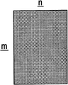
With reference to Figure 19,20,21 and 22 concrete grammar is described.Figure 19 A and 19B show the paper finger print information and the current paper finger print information that obtains of having registered, and each free laterally n * vertically m pixel formed.
In the function of equation (1) expression, i and j by respectively (n+1) in the scope of (n-1) and (m+1) moving in the scope of (m-1) individual element, therefore try to achieve error E between (2n-1) * (2m-1) individual paper finger print information of having registered and the current paper finger print information that obtains (i, j).Promptly try to achieve error E (n+1 ,-m+1) to E (n-1, m-1).
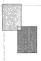
A upper left situation that pixel is overlapping in pixel that Figure 20 A shows in the current paper finger print information that obtains its bottom right only and the paper finger print information of having registered.In this case, the value representation that the represented function of equation (1) is tried to achieve be E (n+1 ,-m+1).Figure 20 B shows the current paper finger print information that obtains with respect to the move right situation of a pixel of the situation shown in Figure 20 A.In this case, the value representation that the represented function of equation (1) is tried to achieve be E (n+2 ,-m+1).Similarly, on one side the mobile current paper finger print information that obtains, one side error of calculation.Figure 20 C shows the current paper finger print information that obtains and is moved until overlapping with the paper finger print information of having registered, thus the situation of the error of trying to achieve (0 ,-(m-1)).In addition, Figure 20 D shows the current paper finger print information that obtains and is moved into right-hand member, thereby tries to achieve error E (n-1 ,-m+1) situation.As mentioned above, along with the current paper finger print information that obtains is laterally moved, (i, j) i in is added 1 to E one by one.
Similarly, Figure 21 A shows the current paper finger print information that obtains and vertically moves down a pixel, thereby tries to achieve error E (n+1 ,-m+2) situation.
And then Figure 21 B shows the current paper finger print information that obtains and is moved into right-hand member from the state of Figure 21 A, thereby tries to achieve error E (n-1 ,-m+2) situation.
It is situation about obtaining from consistent position with the current paper finger print information that obtains that Figure 22 A shows the finger print information of having registered.(i, value j) is represented as E (0,0) to error E in this case.
Similarly, on one side mobile image make the paper finger print information sheet pixel that overlaps each other at least, the error of calculation on one side.Finally, shown in Figure 22 B, try to achieve error E (n-1, m-1).
By like this, try to achieve (2n-1) * (2m-1) individual error E (i, set j).
Now, in order to understand the implication of equation (1), will consider wherein i=0 and j=0, α
1(x, y)=1 (wherein x=0 to n and y=0 to m), and α
2(x-i, y-j)=1 situation of (wherein x=0 to n and y=0 to m).Promptly try to achieve at α
1(x, y)=1 (wherein x=0 to n and y=0 to m), and α
2(x-i, y-j)=1 error E (0,0) under the situation of (wherein x=0 to n and y=0 to m).
I=0 and j=0 represent that shown in Figure 22 A, paper finger print information of having registered and the current paper finger print information that obtains obtain from consistent location.
α
1(all pixels in the paper finger print information of having registered all are bright for x, y)=1 (wherein x=0 to n and y=0 to m) expression.When the paper finger print information of promptly having registered was acquired, obtaining at the paper finger print information did not have the look material such as toner, ink in the zone, do not have dust yet.
α
2(all pixels in the current paper finger print information that obtains all are bright for x-i, y-j)=1 (wherein x=0 to n and y=0 to m) expression.Be the current paper finger print information that obtains when being acquired, obtaining at the paper finger print information does not have the look material such as toner or ink in the zone, do not have dust yet.As mentioned above, work as α
1(x, y)=1 and α
2(x-i y-j)=1 satisfies for all pixels, and equation (1) can be rewritten as following equation (2)
In equation (2), { f
1(x, y)-f
2(x, y) }
2Be illustrated in the gray level image data of the paper finger print information of having registered and the difference between the gray level image data of the current paper finger print information that obtains square.Therefore, equation (2) be illustrated in two paper finger print informations between each pixel difference square summation.Be f
1(x, y) and f
2(x, y) similarly pixel quantity is many more, and the value of E (0,0) is more little.
With above-mentioned method of trying to achieve error E (0,0) similarly, try to achieve other error E (i, j).Because E (0,0) value is along with for f
1(x, y) and f
2(x, y) the similarly increase of pixel quantity and reducing, when E (k, 1)=min{E (i, j) } time, obtain the position of the paper finger print information of having registered as can be known and obtain between the position of the current paper finger print information that obtains, (k, 1) is moved away from each other.
The implication of α
The branch subrepresentation of equation (1) is with { f
1(x, y)-f
2(x-i, y-j) }
2Multiply by α
1And α
2Result's (more accurately, trying to achieve sum of products) by the ∑ symbol.Each α
1And α
2Have 0 value for dense color pixel, and have 1 value for the pixel of light colour.
Therefore, work as α
1And α
2One of (or the two) be 0 o'clock, α
1α
2{ f
1(x, y)-f
2(x-i, y-j) }
2Be 0.
Promptly when the object pixel in arbitrary (or the two) paper finger print information sheet has dense color, do not consider the strength difference on this pixel, do not have thereon pixel thereby not will consider dust or look material.
By this processing, the quantity of the item that adds by the ∑ symbol changes.Therefore, this summation is divided by total quantity ∑ α
1(x, y) α
2(x-i is y-j) to standardize.For the ∑ α in the denominator in equation (1)
1(x, y) α
2(x-i, y-j) become 0 error E (i, j), be not included in the error set E that describes subsequently ((n-1) ,-(m-1)) to E (n-1, m-1) in.
Determine the method for matching degree
As discussed previously, when E (k, 1)=min{E (i, j) } time, obtain the position of the paper finger print information of having registered and the position that obtains the current paper finger print information that obtains as can be known, relative to each other be removed (k, 1).
Then, (i j) tries to achieve the value (this value is called as " matching degree ") of two paper finger print information similarity degrees of expression by use error E (k, 1) and other error E.
At first, the set of the error of trying to achieve from the function of equation (1) expression (E (0,0)=10 for example
*, E (0,1)=50, E (1,0)=50, E (1,1)=50) in, mean value (40) tried to achieve.…(A)
*Symbol is not represented any value, only is used to cause the attention to correlation.The reason that arouses attention will described after a while.
Subsequently, from mean value (40), deduct each error (10
*, 50,50,50) and try to achieve a new set (30
*,-10 ,-10 ,-10).…(B)。
Subsequently, try to achieve standard deviation (30 * 30+10 * 10+10 * 10+10 * 10=1200,1200/4=300, √ 300=10 √ 3 ≈ 17) based on new set.Subsequently, the value in new set is divided by 17, and tries to achieve (1
*,-1 ,-1 ,-1).…(C)
Maximum in these values is confirmed as matching degree (1
*).This value 1
*Be and error E (0,0)=10
*Corresponding value.At this moment, E (0,0) be satisfy E (0,0)=min{E (i, j) } value.
Determine the summary of the method for matching degree
In the processing of determining matching degree, the error amount of minimum and the degree of deviation (A and B) of mean error value in the error of calculation set.
Subsequently, the degree of deviation is tried to achieve matching degree (C) divided by standard deviation.
Finally, matching degree and threshold value are compared, obtain comparative result (D).
Standard deviation is meant the average of difference between each error and the mean value.Be that standard deviation refers to the approximate whole degree of variation in this set.
By (i, j) (i, j} have middle min{E how little (being significantly little or slightly little) divided by representing the whole value that makes a variation, can be identified in to gather E with above-mentioned degree of variation.
When min{E (i, j) } (i, when obviously very little, matching degree is confirmed as effectively, otherwise is confirmed as invalid (D) in j) at set E.
When min{E (i, j) } set E (i, in j) when obviously very little matching degree be confirmed as effective reason
Now, suppose that the paper finger print information of having registered obtains from identical paper with the current paper finger print information that obtains.
At this moment, suppose to exist certain offset that the paper finger print information and the current paper finger print information that obtains of having registered are mated well.In this offset, because paper finger print information of having registered and the current paper finger print information that obtains mate well, (i j) should be very little for E.
On the other hand, even when the very little variation of offset generation, paper finger print information of having registered and the current paper finger print information that obtains have not just had correlation fully.Like this, (i j) should be very big value to E.
Therefore, " two paper finger print informations obtain from identical paper " this condition with " minimum E (and i, j) set E (i, obviously very little in j) " this term harmonization.
Turn back to the description of paper finger print information comparison process now.
In step S903, matching degree and predetermined threshold between two paper finger print informations that will obtain in step S902 compare, and determine that matching degree is " effectively " or engineering noise.Matching degree is also sometimes referred to as similarity.In addition, the result of matching degree and predetermined threshold comparison is called as comparative result sometimes.
It more than is description to controller unit 11.
The description of function screen picture
Fig. 7 shows the initial screen of image processing system 10.Whether zone 701 presentation videos formation device 10 is ready to duplicate and represents duplicating the setting of umber.Original document selector button 704 is used to select the original document kind.When pressing this button, show from three patterns to be the ejection display menu of selecting Text Mode, picture mode and the text/picture pattern.Conclusion button 706 is used to specify the various settings about finishing.The two-sided button 707 that is provided with is used to specify the setting of reading with duplex printing about two-sided.Read mode button 702 is used to select the original document read mode.When pressing this button, show that from three patterns be the ejection display menu of selecting color mode, white-black pattern and automatic (ACS) pattern.Color mode is selected for color photocopying, and white-black pattern is selected for black and white copying.When the ACS pattern was selected, copy mode was determined according to previous described black and white/colored detection signal.
Paper finger print information register button 708 is the buttons that are used to select paper finger print information registration process.Paper finger print information registration process will described after a while.Paper finger print information compare button 709 is the buttons that are used to select paper finger print information comparison process.Paper finger print information comparison process will described after a while.
Then, will paper finger print information registration process performed when paper finger print information register button 708 shown in Figure 7 is pressed by the user and pressed start key subsequently be described with reference to Figure 16.
At step S1601, CPU 301 carries out control, and the view data of the original document that feasible expression scanner 13 reads is sent to scanner image processor 312 by scanner interface 311.
At step S1602, the gain adjustment value that scanner processor 312 is provided with less than common gain adjustment value for shading correction unit 500.Subsequently, be output to paper finger print information acquiring unit 507 by the brightness value of view data being used little gain adjustment value acquisition.Subsequently, based on dateout, paper finger print information acquiring unit 507 obtains the paper finger print information.The paper finger print information that obtains is sent to RAM 302 by the data/address bus (not shown).
In the technology of obtaining the paper finger print information,, obtain darker view data relatively in order from white portion, to obtain the fiber pattern.Therefore, in the present embodiment, be provided with less than the gain adjustment value of gain adjustment value usually, thereby can obtain to be used to obtain the dark view data of paper finger print information by scanner image processor 312.Yet the method that obtains dark view data is not limited to this method.For example, also can adopt the method that reduces the total amount of light in scan period.
At step S1603, CPU 301 request servers send the management number, and will manage information that number and paper finger print information and expression paper finger print information obtain the zone and set up related and be registered in the server.This expression paper finger print information obtains the positional information that regional information is meant the position that obtains the paper finger print information.
At step S1604, CPU 301 carries out control, makes the management number be displayed on the screen.
The operation of when the button that is used for paper finger print information comparison process is pressed, carrying out
Then, will describe after paper finger print information compare button 709 shown in Figure 7 is pressed with reference to Figure 17, and the operation of carrying out after after the input manager number, pressing start key subsequently.
At step S1701, CPU 301 carries out control, and the view data of the original document that feasible expression scanner 13 reads is sent to scanner image processor 312 by scanner interface 311.
At step S1702,312 pairs of view data of scanner image processor are carried out processing shown in Figure 5, produce new view data and attribute data.In addition, scanner image processor 312 appends to attribute data on the view data.
In addition, at step S1702, CPU 301 determines that based on the management number of input the paper finger print information obtains the zone.Subsequently, the paper finger print information acquiring unit 507 in the scanner image processor 312 obtains the zone from the above-mentioned paper finger print information that is determined and obtains the paper finger print information.Subsequently, paper finger print information acquiring unit 507 sends to RAM 302 by the data/address bus (not shown) with the paper finger print information.
In addition, at step S1702, obtain the paper finger print information that is associated with the input manager number of in server, registering.Subsequently, this paper finger print information is sent to RAM302 by the data/address bus (not shown).
At step S1703, CPU 103 will compare by paper finger print information acquiring unit 507 paper finger print information that obtains and the paper finger print information of registering in server.This comparison process formerly is described to the paper finger print information comparison process with reference to figure 9.
At step S1704, CPU 301 carries out control, makes the result (effective or invalid) of paper finger print information comparison process be displayed on the display screen of operating unit 12.
Paper finger print information registration process when printing (carrying out) by main frame
More than described and when duplicating, obtained the paper finger print information and in server, register the method for this paper finger print information.Then, use description to the processing of when printing, obtaining the paper finger print information and registering this paper finger print information.
Now, will the handling process that main frame 40 sends to print command by printed driver one of image processing system 10,20 and 30 be described with reference to flow chart shown in Figure 10.Step S3001 in this flow chart to S3003 by the total control of the CPU in the main frame 40.On the other hand, step S3004 is by the total control of the CPU on the image processing system 10 301.
At step S3001, the user sets setting of printing on the printed driver of main frame 40.Figure 12 shows the example of the screen-picture of printed driver demonstration.The user selects the output type wanted from output type drop-down menu 3201.For example, print when the user wants routine, the user can select " printing ".When the user wants " paper fingerprint registration printing ", user's selection " the paper fingerprint is registered printing ".Selected " registration of paper fingerprint is printed " in this hypothesis.After the user specified output type and clicks " determining " button by drop-down menu 3201, the CPU prompting user of main frame 40 inputed password.
At step S3002, the CPU of main frame 40 detects the password of user's input.Subsequently, processing is transferred to step S3003.
At step S3003, print data and password are sent to the image processing system (for example image processing system 10) of appointment together.
At step S3004, image processing system 10 receives print data, and analyzes print data to produce intermediate data.Subsequently, image processing system 10 is based on the intermediate data generation view data.Subsequently, image processing system 10 is carried out control, makes the CPU 301 of image processing system 10 that view data is stored among the HDD 304 temporarily.
Paper finger print information registration process when printing (carrying out) by image processing system
Then, will the processing of carrying out after the processing that follow flow chart shown in Figure 10 be described with reference to Figure 11.Each step in the flow chart shown in Figure 11 is by the total control of the CPU301 of image processing system.
At first, on function screen shown in Figure 7, the user presses " system mode " button 710.When pressing " system mode " button 710, CPU 301 carries out control, makes the identification information (for example title) of interim all images data of storing be presented on the display screen.The user therefrom specifies the view data of wanting.Subsequently, CPU 301 request input passwords.When user's response request input password, CPU 301 will input password and compare with the password that is provided with at step S3001.When these password couplings, the view data that CPU 301 identification users want.The identification of the view data that this user wants is carried out at step S3101 by CPU 301.
Subsequently, at step S3102, CPU 301 determines to obtain the zone of paper finger print information based on the view data that the user wants.Be that CPU 301 is defined as the paper finger print information with appropriate area and obtains the zone.Describe definite paper finger print information below with reference to Figure 13 and 15 and obtain the method in zone.
At step S3103, CPU 301 is in the message that shows " please place the paper that is used to print and scan paper on the original text platform " on the operating unit 12.In response, the user places on the original text platform and is used for the paper of printout, and presses " determining " key.
At step S3104, the paper on the scanner 13 scanning copy platforms.Then, scanner 13 will send to scanner image processor 312 by scanner interface 311 by the data that scanning obtains.The gain adjustment value that scanner image processor 312 is provided with less than common gain adjustment value for shading correction unit 500.By this set, scanner image processor 312 is applied to little gain adjustment value on the data that obtain by scanning.Subsequently, the luminance signal that obtains is output to paper finger print information acquiring unit 507.
At step S3105, CPU 301 checks that whether all luminance signal all greater than (brighter) or equal predetermined value.In other words, CPU 301 determines among the value of luminance signal whether any value less than predetermined value is arranged.
When any value was arranged in the value in luminance signal less than (secretly in) predetermined value, because the scanning paper that might be used for printing is not blank (step S3105 not), therefore, CPU301 carried out control and makes show alarm on display screen.When the user owing to changing the indication of paper or other reason and rescan, the user rescans in step S3106 indication, step S3104 is carried out once more like this.
On the other hand, when all values of determining luminance signal at step S3105 greater than (brighter) or when equaling predetermined value, the scanning paper that is used for printing is blank (step S3105 is), and handles and change step S3107 over to.
At step S3107, CPU 301 request servers send the management number, and carry out control, and the information that makes management information and paper finger print information and expression paper finger print information obtain the zone is set up related, and is registered in the server.
At step S3108, CPU 301 carries out control, makes the message of " please placing the paper that has scanned on the manual paper feeding pallet " be displayed on the screen.
In response, the user takes away the print paper that obtains its paper finger print information from the original text platform, and places this print paper at step S3109 in the manual paper feeding pallet.
Subsequently, at step S3110, be output on the paper of placing on the manual paper feeding pallet corresponding to the image of view data.When this was finished dealing with, CPU 301 carries out control made the management number be displayed on the screen.
Determine that the paper finger print information obtains the method in zone
Figure 14 determines that the paper finger print information obtains the flow chart of the method in zone.Each step in this flow chart is by the total control of CPU 301.This flow chart shows the appropriate area that search is used to obtain the paper finger print information, and this appropriate area is obtained the processing in zone as the paper finger print information.
At step S3601, CPU 301 carries out control makes the zone on the paper be divided into zone 1 to n.Zone after the division all has identical size, and this size just in time is to obtain the size that the zone is fit to as the paper finger print information.
At step S3602, CPU301 is provided with k=1.
At step S3603, whether CPU 301 checks k=n.When k=n (being among the step S3603), handle changing step S3608 over to.At step S3608, definite failure that CPU 301 execution controls make the expression paper information obtain the zone is displayed on the screen.
When determining that at step S3603 k is not equal to n (among the step S3603 not), handle changing step S3604 over to.At step S3604, k zone is set to the target area.Subsequently, check whether the target area is paper end regions (zone within promptly from the paper end to preset distance).When the target area is the paper end regions (being among the step S3604), handle turning back to step S3603.When the target area is not the paper end regions (among the step S3604 not), handle changing step S3605 over to.
In step S3605, check whether the target area is close to the line of demarcation (zone within from the line of demarcation to the preset distance) with the paper five equilibrium.More specifically, for example, be defined as adjacent domain apart from the zone within the 1cm of line of demarcation.When adjacent sub boundary line, target area (being among the step S3605), handle turning back to step S3603.When the target area is not contiguous marginal zone (among the step S3605 not), handle changing step S3606 over to.
At step S3606, check that based on view data whether the area ratio of target area mid-a bit (or will be equipped with a little) is more than or equal to the first predetermined area ratio (higher area ratio).As the area ratio of determining target area mid-a bit (or will be equipped with a little) during (being among the step S3606), handle turning back to step S3603 more than or equal to the first predetermined area ratio.When the area ratio of determining target area mid-a bit (or will be equipped with a little) during, handle changing step S3607 over to not more than or equal to the first predetermined area ratio (among the step S3606 not).This processing is used to get rid of all black zone.
Described in prior art relevant paragraph before, the pattern of crossed fiber is to read in the zone of white pixel basically.Therefore, all black zone is not suitable for does the paper finger print information and obtains the zone, therefore should get rid of all black zone.
At step S3607, check that based on view data whether the area ratio of target area mid-a bit (or will be equipped with a little) is greater than the second predetermined area ratio (lower side amasss ratio).As the area ratio of determining target area mid-a bit (or will be equipped with a little) during (among the step S3607 not), handle turning back to step S3603 not greater than the second predetermined area ratio regional.When the area ratio of determining target area mid-a bit (or will be equipped with a little) during (being among the step S3607), handle changing step S3609 over to greater than the second predetermined area ratio regional.This processing is used to get rid of white portion.
The reason of carrying out this processing is, because white portion might be cut and be appended on other a piece of paper, makes white portion not be suitable for as the paper finger print information and obtains the zone.
At step S3609, be confirmed as suitable paper finger print information by the definite zone of each step of front and obtain the zone.
At last, the method for trying to achieve the area ratio in the zone that is equipped with point (or will be equipped with a little) based on view data will be described.
At first, the mean concentration of target area is defined as (" scope of brightness value "-" brightness value of each pixel in the target area ") * " being included in the pixel quantity in the target area ".When the brightness value that only may obtain a color (Y of YUV) during as the brightness value of each pixel in the target area, for example " scope of brightness value " is 255.When the brightness value of each pixel in the target area was the brightness value of three colors (among the RGB whole), for example " scope of brightness value " was 255 * 3.
Subsequently, at step S3606 and S3607, the value of this mean concentration and the first predetermined area ratio and the second predetermined area ratio compare.The value of area ratio and mean concentration is converted into the value of same units to compare.
The paper finger print information obtains the example in zone
The view data of supposing temporarily to be stored among the HDD is a view data shown in Figure 15.
When obtaining the paper finger print information from certain zone, when still being all black zone according to this zone of view data, matching degree becomes very low relatively the time.Therefore, it is inappropriate all black zone being obtained the zone as the paper fingerprint.
Therefore, based on the view data that the user wants, CPU 301 specifies the area ratio that is equipped with a little to obtain prohibited area more than or equal to each of first area ratio is regional for the paper finger print information.
In addition, CPU 301 specifies each zone of the paper end regions of corresponding output paper to obtain prohibited area for the paper finger print information.This is because the zone of the paper end regions of corresponding output paper is cut through regular meeting.To obtain the zone cut and when appending to other a piece of paper when the paper finger print information, and the paper finger print information obtains the zone and will be interpreted as on other a piece of paper.
In addition, CPU 301 specifies contiguous marginal each zone with the output paper five equilibrium to obtain prohibited area for the paper finger print information.This is because the user might be at the folding output paper in the middle part of output paper.When output paper is folded, matching degree can reduce, thereby incorrect judgement can take place.
In the zone except the zone of above-mentioned appointment, be equipped with a little area ratio and be confirmed as the paper finger print information less than the zone of predetermined area ratio and obtain the zone.
The view data of supposing temporarily to be stored among the HDD is a view data shown in Figure 13, with reference to Figure 15, stamps the zone of oblique line and all black zone of bottom and is designated as paper finger print information acquisition prohibited area.Other zone obtains the candidate region in zone as the paper finger print information.
In above-mentioned example, suppose output paper for being folded into two parts, make the contiguous marginal zone of branch paper of waiting be designated as paper finger print information acquisition prohibited area.Yet the paper finger print information obtains prohibited area and can determine according to the size of output paper.For example, under the situation of A3 output paper, might suppose that paper will be folded into four parts, determine that the paper finger print information obtains prohibited area.
In addition, can determine that the paper finger print information obtains prohibited area based on paper type.For example, because common being difficult to folding cardboard is two parts, therefore, can not be appointed as paper finger print information acquisition prohibited area with being close to marginal zone.
As mentioned above, according to first embodiment, the view data that is transfused to is divided into a plurality of zones (1 to n), and divides the zone that forms and satisfied the zone of condition after a while from regional 1 beginning search successively.When finding satisfy condition regional, this zone is confirmed as the paper finger print information and obtains the zone.
Condition is summarized as follows:
Condition 1: the zone is not the paper end regions.
Condition 2: the zone is not contiguous marginal zone.
Condition 3: the zone is not the whole white zone.
Condition 4: the zone is not all black zone.
Handle in order to carry out fast, condition 3 and 4 this owing to need determine to be equipped with a little area ratio and become more numerous and diverse processing and in step after a while, carry out, and condition 1 and 2 this not numerous and diverse processing are carried out in the step than morning.
As long as find a zone of satisfying all these conditions, just finish to determine that the paper finger print information obtains the processing in zone.
Second embodiment
Yet, when up in back very the time (for example (n-1) individual zone or n zone) just find when satisfying all conditions regional, can take for a long time according to the processing of first specific embodiment.
On the contrary,, allow the user allow to select desired region, and check whether this desired region satisfies above-mentioned all conditions according to second specific embodiment of the present invention.When all conditions is satisfied in this zone, finish to determine that the paper finger print information obtains the processing in zone.
By so above-mentioned, just allow the user to select desired region from beginning, can reduce to be used for finding the time in the zone of satisfying all conditions.
In addition, can from the zone of user expectation, obtain the paper finger print information.
Figure 18 determines that in the second embodiment of the present invention paper finger print information obtains the flow chart of the processing in zone.
The step of this flow chart is by the total control of CPU 301.
At step S1801, CPU 301 is presented at the image of correspondence image data on the display screen of operating unit 12.In addition, CPU 301 display messages, the prompting user selects the paper finger print information of expectation to obtain the zone from above-mentioned image.When the conduct response, when the user had selected desired region, CPU 301 should select the zone to be set to the target area.
At step S1802, check whether the target area is the paper end regions.When definite target area is not the paper end regions, handle changing step S 1803 over to.When definite target area is the paper end regions, handle changing step S1806 (alarm 1) over to.
At step S1803, check whether the target area is contiguous marginal zone with the paper five equilibrium.When the target area is not contiguous marginal zone, handle changing step S 1804 over to.When the target area is contiguous marginal zone, handle changing step S1807 (alarm 2) over to.
At step S1804, check that based on view data whether the area ratio of target area mid-a bit (or will be equipped with a little) is more than or equal to the first predetermined area ratio (higher area ratio).As the area ratio of determining target area mid-a bit (or will be equipped with a little) during (among the step S1804 not), handle changing step S1805 over to not more than or equal to the first predetermined area ratio.Otherwise, handle changing step S1808 (alarm 3) over to.This processing is used to get rid of all black zone.
Described in prior art relevant paragraph before, basically, the pattern of crossed fiber is to read in the zone of white pixel.Therefore, all black zone is not suitable as the paper finger print information and obtains the zone, therefore should get rid of all black zone.
At step S1805, check that based on view data whether the area ratio of target area mid-a bit (or will be equipped with a little) is greater than the second predetermined area ratio (lower side amasss ratio).As the area ratio of determining target area mid-a bit (or will be equipped with a little) during (being among the step S1805), handle changing step S1810 over to greater than the second predetermined area ratio.Otherwise, handle changing step S1809 (alarm 4) over to.This processing is used to get rid of white portion.
Described in prior art relevant paragraph before, white portion might be cut and be appended on other a piece of paper.Therefore, white portion is not suitable for as the paper finger print information and obtains the zone
At step S1810, the zone of user's appointment is confirmed as suitable paper finger print information and obtains the zone.
At step S1806, CPU 301 carries out control to require the user to select the zone of more close central authorities by display screen.
At step S1807, CPU 301 carries out control to require the user to select the zone of more close paper end by display screen.
At step S1808, CPU 301 carries out control to require the user to select more white region by display screen.
At step S1809, CPU 301 carries out control to require the user to select more black region by display screen.
When as for the response of step S1806 to the message of S1809, the user selects new when regional, and processing turning back to step S1801.
When as for the response of step S1806 to the message of S1809, the user selects " selecting regional automatically ", and processing so shown in Figure 180 is withdrawed from, and processing shown in Figure 14 begins.That is, use the processing of under the situation of first embodiment, describing.
Although the user is allowed to freely select the paper finger print information to obtain the zone at step S1801 in the present embodiment, in addition, when the user carry out the paper finger print information obtain the zone selection the time, can force following restriction (1) and (2):
(1) the paper end regions becomes and becomes the ash demonstration, to forbid selection.
(2) being close to marginal zone becomes the demonstration of change ash, to forbid selection.
In this case, step S1802 and S1803 can omit from flow chart shown in Figure 180.This is used to improve the speed of processing.
In addition, at step S1801, can be on display screen display message come the requirement user to select neither too black be not again too white zone.
Other embodiment
The present invention both can be applied to the system that is made up of multiple arrangement (for example computer, interface equipment, reader, printer etc.) also can be applied to independent device (multi-functional set composite, printer, facsimile machine etc.).
In addition, also can be by allowing computer read and carrying out the program code that is stored on the storage medium and realize the present invention, the program in the flow chart that the said procedure coded representation is described in the content of the various embodiments described above.In this case, the function of each embodiment embodies by the program code that reads from storage medium.
The storage medium that is used to provide program code can be for example floppy disk, hard disk, CD, magneto optical disk, CD-ROM, CD-R, tape, Nonvolatile memory card or ROM.
Though invention has been described with reference to specific embodiment, should be understood that to the invention is not restricted to disclosed specific embodiment.The scope of claim is the explanation that gives broad sense, makes it cover all modifications, equivalent structure and function.
Claims (9)
1. an image processing apparatus is characterized in that, comprising:
Search unit is used for the view data according to input, and on the paper that will be printed from view data, search wherein is equipped with a little area ratio greater than the second predetermined area ratio and less than the zone of the first predetermined area ratio;
Acquiring unit is used for from obtain the paper finger print information as the Search Results of search unit and from the zone that paper finds;
Wherein the first predetermined area ratio is greater than the second predetermined area ratio.
2. image processing apparatus according to claim 1, it is characterized in that, described search unit is used for the zone of the line of demarcation of the paper that will be printed from sub image datas such as distances more than or equal to distance to a declared goal, and search wherein is equipped with a little area ratio greater than the second predetermined area ratio and less than the zone of the first predetermined area ratio.
3. image processing apparatus according to claim 2 is characterized in that it also comprises determining unit, and the type that is used for the paper that will be printed according to view data is determined above-mentioned distance to a declared goal.
4. image processing apparatus according to claim 1, it is characterized in that, described search unit, be used for the zone of the end of the paper that will be printed from the distance view data more than or equal to distance to a declared goal, search wherein is equipped with a little area ratio greater than the second predetermined area ratio and less than the zone of the first predetermined area ratio.
5. an image processing apparatus is characterized in that, comprising:
Division unit is used for input image data is divided into a plurality of zones;
Inspection unit is used for checking each zone in a plurality of zones that the division by division unit forms, and whether the end of the paper that will be printed apart from view data is more than or equal to preset distance;
Acquiring unit is used for being defined as the zone of the end of the paper that will be printed apart from view data more than or equal to preset distance from being examined the unit, obtains the paper finger print information.
6. image processing apparatus as claimed in claim 5 is characterized in that, described preset distance is to determine according to the paper type that view data will be printed.
7. a method of controlling image processing apparatus is characterized in that, this method may further comprise the steps:
The step that input image data is divided into a plurality of zones;
Whether the end of the paper that each zone in a plurality of zones that the division of inspection by division unit forms will be printed apart from view data is more than or equal to the step of preset distance;
From the zone of end more than or equal to preset distance of the paper that is confirmed as by inspection will being printed apart from view data, obtain the step of paper finger print information.
8. control image processing apparatus method according to claim 7 is characterized in that described preset distance is to determine according to the paper type that view data will be printed.
9. a method of controlling image processing apparatus is characterized in that, this method may further comprise the steps:
The step that input image data is divided into a plurality of zones;
Whether the end of the paper that each zone in a plurality of zones that inspection forms by divide image data will be printed apart from view data is more than or equal to the step of first distance;
Whether the line of demarcation that inspection is confirmed as having the paper that each the zone sub image data such as distance grade more than or equal to the distance of first distance will be printed is more than or equal to the step of second distance;
Inspection is confirmed as having each zone more than or equal to the distance of second distance, wherein is equipped with a little area ratio whether greater than the second predetermined area ratio and less than the step of the first predetermined area ratio;
From being confirmed as wherein being equipped with a little area ratio greater than the second predetermined area ratio and less than the step that obtains the paper finger print information the zone of the first predetermined area ratio.
Applications Claiming Priority (2)
| Application Number | Priority Date | Filing Date | Title |
|---|---|---|---|
| JP2006203373 | 2006-07-26 | ||
| JP2006203373A JP4709090B2 (en) | 2006-07-26 | 2006-07-26 | Image processing apparatus, image processing apparatus control method, and program |
Publications (2)
| Publication Number | Publication Date |
|---|---|
| CN101115125A CN101115125A (en) | 2008-01-30 |
| CN100559825C true CN100559825C (en) | 2009-11-11 |
Family
ID=38986386
Family Applications (1)
| Application Number | Title | Priority Date | Filing Date |
|---|---|---|---|
| CNB200710129780XA Expired - Fee Related CN100559825C (en) | 2006-07-26 | 2007-07-26 | The method of image processing apparatus and control image processing apparatus |
Country Status (3)
| Country | Link |
|---|---|
| US (1) | US8077342B2 (en) |
| JP (1) | JP4709090B2 (en) |
| CN (1) | CN100559825C (en) |
Families Citing this family (6)
| Publication number | Priority date | Publication date | Assignee | Title |
|---|---|---|---|---|
| EP1739947B1 (en) * | 2005-06-30 | 2013-10-02 | Canon Kabushiki Kaisha | Density determination method, image forming apparatus, and image processing system |
| EP2126841A2 (en) * | 2007-01-16 | 2009-12-02 | Optasia Medical, Limited | Image processing systems and methods |
| JP4362613B2 (en) * | 2007-07-20 | 2009-11-11 | シャープ株式会社 | Scanner device and information display system including the scanner device |
| US7957173B2 (en) | 2008-10-14 | 2011-06-07 | Mosaid Technologies Incorporated | Composite memory having a bridging device for connecting discrete memory devices to a system |
| US8549209B2 (en) * | 2008-11-04 | 2013-10-01 | Mosaid Technologies Incorporated | Bridging device having a configurable virtual page size |
| US11715314B2 (en) * | 2020-07-07 | 2023-08-01 | Xerox Corporation | Performance improvement with object detection for software based image path |
Family Cites Families (16)
| Publication number | Priority date | Publication date | Assignee | Title |
|---|---|---|---|---|
| JPH11331626A (en) * | 1998-03-09 | 1999-11-30 | Minolta Co Ltd | Image processor |
| JP2001103288A (en) * | 1999-09-30 | 2001-04-13 | Canon Inc | Image processing device and image processing method |
| US7372594B1 (en) * | 1999-09-30 | 2008-05-13 | Canon Kabushiki Kaisha | Image processing apparatus and method, and storage medium |
| JP3610269B2 (en) * | 1999-09-30 | 2005-01-12 | キヤノン株式会社 | Image processing apparatus and image processing method |
| JP3919618B2 (en) * | 2002-07-10 | 2007-05-30 | キヤノン株式会社 | Recording medium discrimination method, program, storage medium, and recording apparatus |
| JP2004042371A (en) * | 2002-07-10 | 2004-02-12 | Canon Inc | Method and program for determining recording medium, recording medium and recorder |
| JP2004112644A (en) | 2002-09-20 | 2004-04-08 | Fuji Xerox Co Ltd | Original-registering device, original-confirming device, and mark for collating original |
| JP4103826B2 (en) * | 2003-06-24 | 2008-06-18 | 富士ゼロックス株式会社 | Authenticity determination method, apparatus and program |
| JP4655615B2 (en) * | 2004-12-10 | 2011-03-23 | 富士ゼロックス株式会社 | Solid identification device and program |
| WO2007012816A1 (en) * | 2005-07-27 | 2007-02-01 | Ingenia Technology Limited | Verification of authenticity |
| US7731435B2 (en) * | 2005-08-12 | 2010-06-08 | Ricoh Company, Ltd. | Techniques for printing with integrated paper sheet identification |
| US7809156B2 (en) * | 2005-08-12 | 2010-10-05 | Ricoh Company, Ltd. | Techniques for generating and using a fingerprint for an article |
| GB2429950B (en) * | 2005-09-08 | 2007-08-22 | Ingenia Holdings | Copying |
| JP4836260B2 (en) * | 2006-12-05 | 2011-12-14 | キヤノン株式会社 | Image forming apparatus, image forming method, recording medium, and program |
| JP4812106B2 (en) * | 2006-12-05 | 2011-11-09 | キヤノン株式会社 | Image reading apparatus and control method thereof |
| US7865124B2 (en) * | 2007-03-30 | 2011-01-04 | Ricoh Company, Ltd. | Pre-scanning printer with paper fingerprinting |
-
2006
- 2006-07-26 JP JP2006203373A patent/JP4709090B2/en not_active Expired - Fee Related
-
2007
- 2007-07-16 US US11/778,370 patent/US8077342B2/en not_active Expired - Fee Related
- 2007-07-26 CN CNB200710129780XA patent/CN100559825C/en not_active Expired - Fee Related
Also Published As
| Publication number | Publication date |
|---|---|
| JP4709090B2 (en) | 2011-06-22 |
| JP2008034944A (en) | 2008-02-14 |
| CN101115125A (en) | 2008-01-30 |
| US8077342B2 (en) | 2011-12-13 |
| US20080025637A1 (en) | 2008-01-31 |
Similar Documents
| Publication | Publication Date | Title |
|---|---|---|
| US7509060B2 (en) | Density determination method, image forming apparatus, and image processing system | |
| CN101197895B (en) | Image processing apparatus and method | |
| CN101296286B (en) | Image forming device | |
| CN101110890B (en) | Image processing apparatus and control method thereof | |
| CN100508547C (en) | Image processing apparatus and image processing method | |
| CN101197897B (en) | Image processing apparatus and image processing method | |
| US6370258B1 (en) | Image processing apparatus and method | |
| CN100505821C (en) | Image processing apparatus, method for controlling same | |
| CN100559825C (en) | The method of image processing apparatus and control image processing apparatus | |
| US8019113B2 (en) | Image processing apparatus, control method therefore, program, and storage medium | |
| CN101197896B (en) | Image processing apparatus, image processing method | |
| JP4812106B2 (en) | Image reading apparatus and control method thereof | |
| US8165338B2 (en) | Image processing apparatus and control method thereof | |
| US8189208B2 (en) | Image processing apparatus, controlling method of image processing apparatus, program and storage medium | |
| US20100053656A1 (en) | Image processing apparatus capable of processing color image, image processing method and storage medium storing image processing program | |
| JP3093493B2 (en) | Image storage and retrieval device | |
| JP3530556B2 (en) | Image forming apparatus and image forming method | |
| JP2008148263A (en) | Image forming apparatus, and its control method | |
| JP3305019B2 (en) | Image processing system and control method for image processing system | |
| JP2008141680A (en) | Image forming apparatus, and control method of image forming apparatus | |
| CN101193191A (en) | Information processing apparatus and control method thereof | |
| JP2010239204A (en) | Image processor, image processing method, program, and storage medium | |
| JP2009267610A (en) | Image processing device and image processing method | |
| JP2008310027A (en) | Image forming apparatus, image forming method, recording medium and program | |
| JP2008244611A (en) | Image processing unit and image processing method |
Legal Events
| Date | Code | Title | Description |
|---|---|---|---|
| C06 | Publication | ||
| PB01 | Publication | ||
| C10 | Entry into substantive examination | ||
| SE01 | Entry into force of request for substantive examination | ||
| C14 | Grant of patent or utility model | ||
| GR01 | Patent grant | ||
| CF01 | Termination of patent right due to non-payment of annual fee | ||
| CF01 | Termination of patent right due to non-payment of annual fee |
Granted publication date: 20091111 Termination date: 20180726 |