CN100554868C - Position-measurement device - Google Patents
Position-measurement device Download PDFInfo
- Publication number
- CN100554868C CN100554868C CNB2006100996840A CN200610099684A CN100554868C CN 100554868 C CN100554868 C CN 100554868C CN B2006100996840 A CNB2006100996840 A CN B2006100996840A CN 200610099684 A CN200610099684 A CN 200610099684A CN 100554868 C CN100554868 C CN 100554868C
- Authority
- CN
- China
- Prior art keywords
- measuring body
- optical grating
- divided beams
- measurement
- measurement device
- Prior art date
- Legal status (The legal status is an assumption and is not a legal conclusion. Google has not performed a legal analysis and makes no representation as to the accuracy of the status listed.)
- Active
Links
- 238000005259 measurement Methods 0.000 title claims abstract description 112
- 230000003287 optical effect Effects 0.000 claims abstract description 121
- 238000010276 construction Methods 0.000 claims abstract description 104
- 230000009471 action Effects 0.000 claims abstract description 33
- 239000000758 substrate Substances 0.000 claims description 15
- 230000000694 effects Effects 0.000 claims description 11
- 230000010287 polarization Effects 0.000 claims description 11
- 238000001514 detection method Methods 0.000 claims description 10
- 238000006073 displacement reaction Methods 0.000 claims description 8
- 238000000926 separation method Methods 0.000 claims description 8
- 230000008859 change Effects 0.000 claims description 3
- 230000007246 mechanism Effects 0.000 claims description 2
- 238000000034 method Methods 0.000 description 5
- 230000010363 phase shift Effects 0.000 description 4
- 230000008901 benefit Effects 0.000 description 3
- 238000007639 printing Methods 0.000 description 3
- 230000033228 biological regulation Effects 0.000 description 2
- 230000015572 biosynthetic process Effects 0.000 description 2
- 239000004020 conductor Substances 0.000 description 2
- 230000001447 compensatory effect Effects 0.000 description 1
- 230000008878 coupling Effects 0.000 description 1
- 238000010168 coupling process Methods 0.000 description 1
- 238000005859 coupling reaction Methods 0.000 description 1
- 238000010586 diagram Methods 0.000 description 1
- 238000005516 engineering process Methods 0.000 description 1
- 230000002349 favourable effect Effects 0.000 description 1
- 239000011521 glass Substances 0.000 description 1
- 230000002452 interceptive effect Effects 0.000 description 1
- 230000000737 periodic effect Effects 0.000 description 1
- 230000005622 photoelectricity Effects 0.000 description 1
- 230000001902 propagating effect Effects 0.000 description 1
- 230000011514 reflex Effects 0.000 description 1
Images


Classifications
-
- G—PHYSICS
- G01—MEASURING; TESTING
- G01D—MEASURING NOT SPECIALLY ADAPTED FOR A SPECIFIC VARIABLE; ARRANGEMENTS FOR MEASURING TWO OR MORE VARIABLES NOT COVERED IN A SINGLE OTHER SUBCLASS; TARIFF METERING APPARATUS; MEASURING OR TESTING NOT OTHERWISE PROVIDED FOR
- G01D5/00—Mechanical means for transferring the output of a sensing member; Means for converting the output of a sensing member to another variable where the form or nature of the sensing member does not constrain the means for converting; Transducers not specially adapted for a specific variable
- G01D5/26—Mechanical means for transferring the output of a sensing member; Means for converting the output of a sensing member to another variable where the form or nature of the sensing member does not constrain the means for converting; Transducers not specially adapted for a specific variable characterised by optical transfer means, i.e. using infrared, visible, or ultraviolet light
- G01D5/32—Mechanical means for transferring the output of a sensing member; Means for converting the output of a sensing member to another variable where the form or nature of the sensing member does not constrain the means for converting; Transducers not specially adapted for a specific variable characterised by optical transfer means, i.e. using infrared, visible, or ultraviolet light with attenuation or whole or partial obturation of beams of light
- G01D5/34—Mechanical means for transferring the output of a sensing member; Means for converting the output of a sensing member to another variable where the form or nature of the sensing member does not constrain the means for converting; Transducers not specially adapted for a specific variable characterised by optical transfer means, i.e. using infrared, visible, or ultraviolet light with attenuation or whole or partial obturation of beams of light the beams of light being detected by photocells
- G01D5/36—Forming the light into pulses
- G01D5/38—Forming the light into pulses by diffraction gratings
-
- G—PHYSICS
- G01—MEASURING; TESTING
- G01D—MEASURING NOT SPECIALLY ADAPTED FOR A SPECIFIC VARIABLE; ARRANGEMENTS FOR MEASURING TWO OR MORE VARIABLES NOT COVERED IN A SINGLE OTHER SUBCLASS; TARIFF METERING APPARATUS; MEASURING OR TESTING NOT OTHERWISE PROVIDED FOR
- G01D5/00—Mechanical means for transferring the output of a sensing member; Means for converting the output of a sensing member to another variable where the form or nature of the sensing member does not constrain the means for converting; Transducers not specially adapted for a specific variable
- G01D5/26—Mechanical means for transferring the output of a sensing member; Means for converting the output of a sensing member to another variable where the form or nature of the sensing member does not constrain the means for converting; Transducers not specially adapted for a specific variable characterised by optical transfer means, i.e. using infrared, visible, or ultraviolet light
- G01D5/32—Mechanical means for transferring the output of a sensing member; Means for converting the output of a sensing member to another variable where the form or nature of the sensing member does not constrain the means for converting; Transducers not specially adapted for a specific variable characterised by optical transfer means, i.e. using infrared, visible, or ultraviolet light with attenuation or whole or partial obturation of beams of light
- G01D5/34—Mechanical means for transferring the output of a sensing member; Means for converting the output of a sensing member to another variable where the form or nature of the sensing member does not constrain the means for converting; Transducers not specially adapted for a specific variable characterised by optical transfer means, i.e. using infrared, visible, or ultraviolet light with attenuation or whole or partial obturation of beams of light the beams of light being detected by photocells
- G01D5/347—Mechanical means for transferring the output of a sensing member; Means for converting the output of a sensing member to another variable where the form or nature of the sensing member does not constrain the means for converting; Transducers not specially adapted for a specific variable characterised by optical transfer means, i.e. using infrared, visible, or ultraviolet light with attenuation or whole or partial obturation of beams of light the beams of light being detected by photocells using displacement encoding scales
- G01D5/34707—Scales; Discs, e.g. fixation, fabrication, compensation
- G01D5/34715—Scale reading or illumination devices
Landscapes
- Physics & Mathematics (AREA)
- General Physics & Mathematics (AREA)
- Optical Transform (AREA)
- Length Measuring Devices By Optical Means (AREA)
Abstract
The present invention relates to a position-measurement device that is used to obtain a scanning element and a relative position of mobile measuring body at least one direction of measurement.This scanning element comprises a plurality of optical grating constructions and at least one reflecting element.Described element is arranged on the scanning element the inside, feasible light beam by the measuring body diffraction passes first optical grating construction in scanning element, then be apparent on the reflecting element, be implemented in a retroeflection on the measuring body direction by reflecting element and make divided beams pass second optical grating construction then and then be apparent on the measuring body again.Constitute first and second optical grating constructions like this, make divided beams for the first time and for the second time by the time produce a definite lens refraction action for divided beams.
Description
Technical field
The present invention relates to a kind of position-measurement device.
Background technology
For example by WO 02,/23 131 known such position-measurement device.This device also comprises a relatively-movable scanning element at least one direction of measurement except a measuring body that for example is made of the luminous dip stick of straight line.At the detecting unit that a plurality of photoelectricity also are set except a raster on the scanning element side, comprising the optical reflection element of at least one retroreflector form.Realize divided beams retroeflection on the direction of measuring body of reflecting first by measuring body by this retroreflector.There before the divided beams of interfering finally arrives detecting device and produces the sweep signal of modulation according to displacement there, divided beams is then reflected for the second time then.Reflecting element is made of the roof prism with optics retroeflection function in this position-measurement device.For example by known other the position-measurement device of document EP 387 520 B1 or EP 1 347271 A1 with the optical reflection element that constitutes by lens type retroeflection element.
The reflecting element that is changed to the basis by the known prism with different of the prior art of position-measurement device is bothersome relatively for the structure member of processing.Make this structure member make relatively largely and therefore strengthen undesirably scanning element for this reason.
Summary of the invention
The objective of the invention is, realize a position-measurement device, wherein guarantee a compact as far as possible scanning element structure.
This purpose is achieved by a kind of position-measurement device according to the present invention.
This position-measurement device comprises:
-measuring body and
-with respect to the scanning element that measuring body moves at least one direction of measurement, wherein this scanning element comprises a plurality of optical grating constructions and at least one reflecting element, wherein
-described position measurement mechanism can obtain the relative position of scanning element with respect to measuring body,
It is characterized in that,
-described a plurality of optical grating constructions and described at least one reflecting element are arranged on the scanning element the inside, make and on the direction of scanning element, propagating by the light beam of measuring body diffraction, these light beams pass first optical grating construction there, then be apparent on the reflecting element, be implemented in retroeflection on the direction of measuring body by reflecting element, and pass second optical grating construction by the divided beams that the retroeflection on the direction of measuring body is reflected and also then on measuring body, manifest again, and
-wherein construct first and second optical grating constructions, make described divided beams respectively by the time lens refraction action that on described divided beams, produce to determine.
Give favourable embodiment according to position-measurement device of the present invention.
According to the present invention's regulation, described element is arranged on the scanning element the inside, makes and propagate on the scanning element direction on the beam diffraction ground that produces on the measuring body that these light beams pass first optical grating construction there.Then divided beams arrives reflecting element, by the retroeflection of reflecting element realization on the measuring body direction, makes divided beams pass second optical grating construction also again on measuring body afterwards.Construct first and second optical grating constructions at this, make divided beams for the first time by and for the second time by the time on divided beams, produce a definite lens refraction action.
Replace the retroeflection element based on prism complicated and that large volume constitutes to use a structural unit according to the present invention in scanning element, it is made up of one or more simple reflecting elements and first and second optical grating constructions with definite optical lens refraction action.Bearing the function that a retroeflection function is also being born a raster simultaneously at this optical grating construction.Can realize a planar structure of this structural unit thus, it also can realize the simple and economic assembling of this structural unit.
Described optical grating construction and at least one reflecting element can be arranged on different parts, for example on reflecting plate and the scanning board.But equally also can realize the one-piece construction of a compactness, wherein optical grating construction and at least one reflecting element are arranged on the unique support substrate.
By first optical grating construction time, be preferably on the direction of measurement and produce one with the deflecting action of incident direction antiparallel orientations and produce one perpendicular to the focussing force of direction of measurement towards reflecting element as the lens refraction action.By second optical grating construction time, produce a deflecting action and the collimating effect on direction of measurement perpendicular to direction of measurement as the lens refraction action.
Preferably in addition constitute described first and second optical grating constructions, make pass through the deflecting action that produced for the first time and for the second time by the time producing on first and second optical grating constructions one divided beams manifest a little between pattern displacement.
First and second optical grating constructions are made of phase grating in an embodiment in the cards, and they suppress 0 order diffraction level (Beugungsordnung).
Particularly advantageous is that described first and second optical grating constructions are made of light (geblazt) phase grating, and it has high-level efficiency in+1 order diffraction level or in-1 order diffraction level.
Can make described first and second optical grating constructions have crooked grid stroke at this, they equidistantly are provided with on direction of measurement.
Constitute by the flat mirror reflects device at least one reflecting element described in the embodiment in the cards.
Described flat mirror reflects device preferably is parallel to measuring body and is arranged on the scanning element the inside.
Comprise a transparent support substrate in scanning element described in the advantageous embodiments, in the face of on the side of measuring body first and second optical grating constructions are set at it.At least one flat mirror reflects device or be arranged on the side in contrast to this of support substrate, wherein the reflecting surface of this flat mirror reflects device is aimed at the measuring body direction.Also can select to make at least one flat mirror reflects device to be arranged on the same side of support substrate, wherein the reflecting surface of flat mirror reflects device is back to measuring body.
Preferably constitute described first and second optical grating constructions, make after manifesting on the measuring body, on the scanning element direction, propagate collimatedly for the second time a first time at the collimation divided beams that manifests on the measuring body.
Different optical grating constructions has the focal length corresponding to the optical range between optical grating construction and the reflecting element in an advantageous manner.
In according to an embodiment in the cards of position-measurement device of the present invention, constitute described scanning element, make the light beam that sends by a light source on measuring body, manifest for the first time, measuring body is made of reflective diffraction grating, be separated into the divided beams of two retroeflections to scanning element there, they are corresponding to two different orders of diffraction.The divided beams of two retroeflections passes two first optical grating constructions and obtains a deflecting action and one focussing force perpendicular to direction of measurement with the incident direction antiparallel orientations at this on the direction of two reflecting elements in scanning element.The divided beams of this deflection and focusing is mapped on the reflecting element and obtains the retroeflection on the measuring body direction.The divided beams of two retroeflections on the measuring body direction, pass two second optical grating constructions and obtain simultaneously one on direction of measurement deflecting action and one only perpendicular to the collimating effect of direction of measurement.Two divided beams are mapped on the measuring body again, make divided beams produce new diffraction and retroeflection there on the direction of scanning element.
In according to the embodiment of a replacement of position-measurement device of the present invention, constitute described scanning element, make the light beam that sends by a light source on measuring body, manifest for the first time, measuring body is made of reflective diffraction grating, be separated into the divided beams of two retroeflections to scanning element there, they are corresponding to two different orders of diffraction.The divided beams of two retroeflections passes two first optical grating constructions and obtains one with the deflecting action of incident direction antiparallel orientations and at direction of measurement and perpendicular to the focussing force on the direction of measurement at this on the direction of two reflecting elements in scanning element.The divided beams of this deflection and focusing is mapped on the reflecting element and obtains the retroeflection on the measuring body direction.The divided beams of two retroeflections on the measuring body direction, pass two second optical grating constructions and obtain simultaneously one on direction of measurement deflecting action and one not only at direction of measurement but also perpendicular to the collimating effect of direction of measurement.Two divided beams are mapped on the measuring body again, make divided beams produce new diffraction and retroeflection there on the direction of scanning element.
A flexible program regulation in the cards according to position-measurement device of the present invention, separate on the grating at one perpendicular to the divided beams stack ground of retroeflection after the retroeflection of scanning element direction by measuring body for the second time and to manifest, be implemented in the separation on a plurality of direction in spaces there and on a plurality of detecting devices of the divided beams that separates on the different spaces direction, manifest at a photoelectric detection system.Under the situation of scanning element and measuring body relative motion, realize a sweep signal of modulating there respectively according to displacement.
In this flexible program, can stipulate, the element of optics polarization perhaps is set in light path between the reflecting element and second optical grating construction or between second optical grating construction and measuring body, divided beams on reflecting element after the retroeflection by the optics polarization element and make the linearly polarized divided beams change into the divided beams of circular polarisation.
For the sweep signal that produces phase shift also can be stipulated, perhaps two first select differently slightly with the average grating constant of two second optical grating constructions with the grating constant of measuring body or the grating lines of two first and two second optical grating constructions with a grating lines setting that departs from 0 ° angle with respect to measuring body.
Has the effective window of an optics position in this external light path according to position-measurement device of the present invention, the light beam that is sent by light source was passing this window position for the first time before manifesting on the measuring body, wherein in the effective window of optics position a deflection grating is set, its grating lines are parallel to direction of measurement and extend.
Description of drawings
By means of explaining other details of the present invention and advantage for the description of embodiment below in conjunction with accompanying drawing.In the accompanying drawing:
Fig. 1 is the first according to the scanning light path of first embodiment of position-measurement device of the present invention;
Fig. 2 is the second portion according to the scanning light path of first embodiment of position-measurement device of the present invention;
Fig. 3 is another view according to the scanning light path of first embodiment of position-measurement device of the present invention;
Fig. 4 is the vertical view according to the scanning board of first embodiment of position-measurement device of the present invention;
Fig. 5 is the vertical view according to the reflecting plate of first embodiment of position-measurement device of the present invention;
Fig. 6 a and 6b are respectively the flexible program selected that is used to constitute reflecting element and optical grating construction in the scanning element of first embodiment;
Fig. 7 is the scanning light path figure according to another flexible program of first embodiment of position-measurement device of the present invention;
Fig. 8 is the vertical view of the scanning board of the position-measurement device among Fig. 7;
Fig. 9 is the vertical view of the rotor of the position-measurement device among Fig. 7;
Figure 10 is the first according to the scanning light path of second embodiment of position-measurement device of the present invention;
Figure 11 is the second portion according to the scanning light path of second embodiment of position-measurement device of the present invention;
Figure 12 is another view according to the scanning light path of second embodiment of position-measurement device of the present invention.
Embodiment
By means of first embodiment of Fig. 1-5 description according to position-measurement device of the present invention, this position-measurement device is made of luminescent system below.At this Fig. 1 and 2 the side view of part scanning light path in the x-z plane is shown with synoptic diagram respectively, and Fig. 3 illustrates the scanning light path figure of scanning light path in the y-z plane.Shown in Figure 1 from the scanning light path of light source 21 up to reflecting element 26.1 or 26.2, Fig. 2 illustrates from reflecting element 26.1 or 26.2 until the scanning light path of the detecting element 29.1,29.2,29.3 of photoelectric detection system.Figure 4 and 5 illustrate scanning board 25 and reflecting plate 23 and the vertical view that is positioned at the optical element respectively there.
Comprise a measuring body 10 and a scanning element 20 that at least one direction of measurement x, relatively moves according to position-measurement device of the present invention.By measuring body 10 and scanning element 20 in known manner with method coupling to determine the object of its relative position by means of position-measurement device.At this for example can be a machine parts, must accurately obtain its position; The sweep signal or the position data that produce by position-measurement device are for example continued to handle in order to control machine by a unshowned postorder circuit (Folgeelektronik) or analytic unit.
A position-measurement device is shown in the embodiment shown, is used for by a linearly extended measuring body detection of straight lines motion; Can certainly be according to thought of the present invention to serve as the position-measurement device that a rotation is realized on the basis.
Below by means of the basic scanning light path of Fig. 1-5 description according to first embodiment of position-measurement device of the present invention.
In the embodiment shown by light source 21, for example the linearly polarized light beam that sends of laser diode promptly converts a parallel light beam at first by a collimating mirror 22 collimations.Then make this light beam pass the invalid window position 28.1,27 of the optics with a scanning board 25 of a reflecting plate 23.By a tabular transparent support substrate, for example form, a series of optical elements are set, at reflecting plate 23 shown in this example and scanning board 25 thereon as reflecting element 26.1,26.2 and optical grating construction 24.1-24.4,32 by glass.Also to be described in detail in the concrete function of optical elements different in the scanning light path below.
Then make the light beam of collimation be mapped to measuring body 10 for the first time, it is made of the reflective chi of straight line in this embodiment.This measuring body 10 comprises the scale zone structure in a cycle of extending on direction of measurement x, it has different optical characteristics.Measuring body 10 is reflection-diffraction grating in the present embodiment, and its grating lines extend upward at given y in the measuring body plane; Also can be called so-called line orientations y below to this.
Be divided into two divided beams when the light beam of incident occurs on measuring body 10, the order of diffraction of their conducts+/-1 grade is in retroeflection on the direction of scanning element 20.Divided beams passes first optical grating construction 24.1,24.2 respectively in scanning element 20, and they are arranged on the scanning board 25 there.First optical grating construction 24.1,24.2 applies a definite optical lens refraction action according to the present invention for the divided beams that passes.Relate in one aspect to a deflecting action of determining at this, wherein make divided beams and incident direction antiparallel ground (antiparallel) at direction of measurement x upper deflecting for divided beams.On the other hand for divided beams relate to one on perpendicular to direction of measurement, promptly y to or on the line orientations of measuring body 10, divide the focussing force that is clipped to rearmounted reflecting element 26.1,26.2.Described focussing force on line orientations y shown in Figure 3; The foregoing deflecting action and the main direction of propagation of two divided beams of expression in Fig. 1.
In order to realize this lens refraction action of first optical grating construction 24.1,24.2, first optical grating construction 24.1,24.2 is made of on scanning board 25 so-called axle outside cylinder lens (offaxis-Zylinderlinsen).Its focal length corresponding to the optical range of reflecting plate 23.The main beam that the divided beams that makes focusing is played in the formation of this optical characteristics of first optical grating construction 24.1,24.2 is being mapped on the reflecting plate 23 with a definite angle on the line orientations y and is being created in the effect of the divided beams apart of incident and reflection on the reflecting plate 23 thus; To this referring to Fig. 3.
The vertical view of scanning board shown in Figure 4 25 and first optical grating construction 24.1,24.2 disposed thereon.As can be seen, first optical grating construction 24.1,24.2 has crooked grid stroke respectively, and they equidistantly are provided with on direction of measurement x.First optical grating construction 24.1,24.2 preferably is made of phase grating, and they suppress 0 order diffraction level; Particularly advantageous is so-called bright phase grating, and they have a high-level efficiency in+1 order of diffraction or in-1 order of diffraction.
Then make the divided beams of this deflection and focusing arrive reflecting element 26.1,26.2, they are arranged in the embodiment shown on the end face of reflecting plate 23 and by the flat mirror reflects device and constitute.
Realize that by reflecting element 26.1,26.2 divided beams is in a retroeflection on measuring body 10 directions.Before divided beams arrives measuring body 10 for the second time, these divided beams at first also pass the optics polarization element 31.1 of a λ/4 plate forms respectively in scanning element 20 in the embodiment shown, 31.2 also then pass second optical grating construction 24.3,24.4, they are arranged on the scanning board 25 equally.To this still referring to accompanying drawing 3.
Produce the divided beams of circular polarisation on the contrary by optics polarization element 31.1,31.2 respectively by the linearly polarized divided beams.Second optical grating construction 24.3,24.4 has a definite lens refraction action equally for the divided beams that passes.The divided beams of this circular polarisation obtain one in the deflecting action on the direction of measurement x and at least one perpendicular to direction of measurement x, i.e. collimating effect on line orientations y.Second optical grating construction 24.3,24.4 preferably is made of so-called axle outer lens in this embodiment; Its leeway please refer to first optical grating construction 24.1,24.2 for the corresponding formation of present embodiment.
Because the described deflecting action that produces for the first time with for the second time by optical grating construction 24.1-24.4 the time makes divided beams produce the pattern displacement between first and second of divided beams manifests a little on the first and second optical grating construction 24.1-24.4.
Then make by second optical grating construction 24.3,24.4 the divided beams of the deflection and (part) collimation that makes progress at y at least arrives measuring body 10 for the second time like this, makes divided beams produce new diffraction and retroeflection with the form of+/-1 order diffraction level on the direction of scanning element 20 there.On measuring body 10 reflection back perpendicular to the divided beams of the direction retroeflection of scanning element 20 as stack, remain the linearly polarized light beam now and enter and separate grating 32, separate grating and be arranged on the scanning board 25.The relative position that depends on measuring body 10 and scanning element 20 in the polarised direction of separating the light beam that occurs on the grating 32.If measuring body 10 for example moves 1/4th of its grating constant on direction of measurement x, then since produced produce one 360 ° the phase shift between the divided beams of stack at the diffraction second time in+/-1 order diffraction level on the measuring body 10.The polarised direction of the linear polarization light beam that is produced changes 180 °, this in the sweep signal that is produced corresponding to a signal period.
The separation grating 32 of described example has a periodic separation structure on direction of measurement x, and its line-dividing extends upward at y.On separation grating 32, make the light beam of incident on three different direction in spaces, produce separation as shown in the figure.Locate the detecting element 29.1-29.3 of a photoelectric detection system on different direction in spaces respectively, the light beam of separation arrives on the detecting element later at the invalid window position of passing on the reflecting plate 23 28.2 of optics.Produce the sweep signal of modulating according to displacement under the situation that measuring body 10 and scanning element 20 relatively move on detecting element 29.1-29.3, they proceed to handle with method in known manner.The optics polarization element 30.1-30.3 of another polarizer form is set respectively in the front of detecting element 29.1-29.3, is used in this way producing three to differ+sweep signal of/-120 ° of phase places with method.
The great advantage of described position-measurement device is, replaces being used for realizing can combine with the simple plane mirror reflection device optical grating construction of the first and second optical grating construction forms of using a best diffraction of the complicated prism of deflection and raster function at the scanning light path of scanning element.
Described first embodiment can also change within the scope of the invention or replenish; Some variation schemes of brief description.
Can make the optics polarization element 31.1 that plays the divided beams that makes the linearly polarized divided beams convert opposite circular polarisation to, 31.2 be not arranged on reflecting element 26.1,26.2 with second optical grating construction 24.3,24.4 between, but in follow-up light path, just be arranged between second optical grating construction 24.3,24.4 and the measuring body 10.
Reflecting element 26.1,26.2 also is arranged on the bottom surface of reflecting plate 23 fully.
Replace the above-mentioned optics polarization flexible program that is used to produce the sweep signal of phase shift also can select to produce same signal within the scope of the invention.Can consider known so-called vernier (Vernier) or Ah (Moir é) scanning theory not for this reason, wherein select the angular orientation (Moir é system) that makes measuring body and the grating constant different slightly (Vernier systems) or the selection of first and second optical grating constructions have a little difference.Produce the striated pattern of one-period in detection plane, it is modulated according to displacement and can be by known mode and method scanning.
Save in this embodiment described first embodiment all optics polarization structure parts, be above-mentioned λ/4 plates 31.1,31.2, polarizer 30.1,30.2,30.3 and separate grating 32.In the detection plane of this embodiment, for example can locate a so-called pick-up unit that forms structure, be implemented in the scanning of the striated pattern that the there produces and convert thereof into the sweep signal of phase shift by it.The optical grating construction that also can select to use optical texture parts such as cylindrical lens array in this embodiment or combine with area detector except that the flexible program of this detection is used to scan striated pattern.
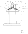
In another version, can in scanning element, stipulate according to first embodiment of position-measurement device of the present invention, replace scanning board separately and reflecting plate to select the structure of an integral body, wherein only have a unique transparent rack substrate, different optical grating constructions not only is set thereon but also reflecting element is set.In Fig. 6 a and 6b, schematically illustrate respective embodiments.
View with prior figures 3 in the example of Fig. 6 a seemingly is illustrated in the corresponding construction parts in the scanning light path in the y-z plane with a partial view.The element that replaces independently being used for scanning board and reflecting plate has a unique transparent support substrate 40, in its bottom surface or in the face of on the side of unshowned measuring body first and second optical grating constructions 44.1,44.2 is set.Still the reflecting element 46.1 that is made of simple plane mirror reflection device is being set on the opposite side or on the end face of support substrate 40.
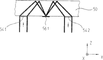
Fig. 6 b illustrates an integrally-built similar variation scheme.Still have only a unique transparent support substrate 50, wherein optically important element and reflecting element 56.1 with first and second optical grating constructions, 54.1,54.2 forms all are arranged on the bottom surface of support substrate.Divided beams required deflection on the opposite end face of support substrate 50 for example can realize by other reflecting element or the reflection horizon that are positioned at the there.
If for according to the one-piece construction light beam gradient of Fig. 6 a or Fig. 6 b in support substrate 50 because corresponding trickle optical grating construction 44.1,44.2,54.1,54.2 and sufficiently big produces total reflection thus, then can save fully and settle the reflection horizon.Trickleer optical grating construction 44.1,44.2,54.1,54.2 provides significant advantage at this, produces the order of diffraction still less and keep more luminous power thus in the desired order of diffraction.
Another alternate embodiments is to make light source be combined in the scanning element the inside forcibly as described in the above-mentioned example.Light source is provided with away from scanning element ground and make diffracted beam by optical conductors carry to scanning element.
Be effectively too for the detecting element of photoelectric detection system in addition, that is, they equally can be spatially be provided with dividually with oneself scanning element.Make the divided beams of wanting detected for example arrive detecting element then by optical conductors carry.
In Fig. 7-9, schematically illustrate another flexible program of first embodiment.Function components identical at this this embodiment is represented by the Reference numeral consistent with above-mentioned example.Below the part different with above-mentioned example only described, remainder please refer to the foregoing description.
In this flexible program, stipulate, in for the light path in the above-mentioned example, in the invalid window of the optics position 27,28.1,28.2 of scanning board and reflecting plate 25,23 deflection grating 27.1,28.3 is set respectively.Described deflection grating 27.1,28.3 has line-dividing respectively, and they are arranged on y upwards and extend periodically on direction of measurement x.It is consistent selecting the periodicity of two deflection gratings 27.1,28.3 in the effective window of optics position.
The existence in light path in the respective window position of scanning board and reflecting plate 23,25 of this deflection grating 27.1,28.3 has the effect of possible wavelength variations that can compensatory light.In addition, manifest when moving o'clock in first and second optical grating constructions when first and second, this just means that seemingly effectively measurement point moves, because the possible wavelength variations of the first and second optical grating construction 24.1-24.4 that diffraction ground constitutes may play a beam deviation of not expecting in the effect of y to top offset.It is constant that the layout of described deflection grating 27.1,28.3 manifests the beam deviation or the effective measurement point of a little also remaining valid thus as the possible wavelength variations acting in opposition of making of defined in first and second.
Certainly also can combine and realize different, the embodiment of selection discussed above with this flexible program.
Below by means of second embodiment of Figure 10-12 description according to position-measurement device of the present invention.Basic structure and scanning light path route according to this embodiment of position-measurement device of the present invention are identical with described first embodiment basically.Therefore important difference is only described below.
First optical grating construction 124.1,124.2 as the lens refraction action except the function according to first example of Fig. 1-5 also have one additional for the focussing force of the divided beams that passes through on direction of measurement x.This point for example in Figure 10 as can be seen.First optical grating construction constitutes at this axle outer lens as the respective design size, its focal length corresponding to the optical range of reflecting plate 123.The main beam that the divided beams that makes focusing is played in this design of the optical characteristics of first optical grating construction 124.1,124.2 vertically arrives the effect of reflecting plate 123 on direction of measurement x, and is in a definite angle on line orientations y.Select this angle, make incident and the divided beams that reflexes on the reflecting plate 123 still upwards realize an apart at y.At reflecting element 126.1,126.2 pass second optical grating construction 124.3 after the last reflection, 124.4 the time described divided beams still obtain one with at optical lens refraction action identical described in the above-mentioned example, that is, realize a collimation with antiparallel deflection of incident direction and divided beams.
First optical grating construction 124.1,124.2 that constitutes as the axle outer lens makes each divided beams focus on the direction x of two sides at this in this embodiment, y last and so with its optical lens refraction action corresponding to common cylindrosymmetric lens.Be that the axle outside cylinder lens of first example only upwards have the lensing of a focussing force form at y in this difference.
For according to the concrete function of this embodiment of position-measurement device of the present invention importantly, described reflecting plate 123 is parallel to the measuring body setting as far as possible in addition.
Therefore the additional optics by first optical grating construction acts on the reflection function of realizing the optics that the acting in conjunction in the scanning light path is formed by optical grating construction 124.1-124.4 and reflecting element 126.1,126.2 among this embodiment.Replace one such with at present by same reflection functions of realizing such as bothersome triangular prisms, identical optical effect is realized by the obvious simple diffraction element that constitutes.
And embodiment also can realize the selectable measure that all are above-mentioned hereto,, also has various flexible programs for this embodiment according to position-measurement device of the present invention in scope of the present invention that is.
To point out at last, replace above-mentioned reflective position-measurement device and also constitute the printing opacity position-measurement device certainly according to the present invention.For example the device of the scan-side of forming by first optical grating construction, reflecting plate and second optical grating construction also can be used for making from the divided beams of printing opacity measuring body its for the first time by this measuring body later on again deflection turn back to printing opacity measuring body etc.Corresponding scanning element must be surrounded measuring body with method in known manner.
Claims (20)
1. position-measurement device comprises:
-measuring body and
-with respect to the scanning element that measuring body moves at least one direction of measurement, wherein this scanning element comprises a plurality of optical grating constructions and at least one reflecting element, wherein
-described position measurement mechanism can obtain the relative position of scanning element with respect to measuring body,
It is characterized in that,
-described a plurality of optical grating constructions and described at least one reflecting element are arranged on scanning element (20; 120) the inside makes by measuring body (10; 110) light beam of diffraction is towards scanning element (20; 120) propagate on the direction, these light beams pass first optical grating construction (24.1,24.2 there; 124.1,124.2), then be apparent in reflecting element (26.1,26.2; 126.1,126.2) on, be implemented in towards measuring body (10 by reflecting element; 110) retroeflection on the direction, and pass second optical grating construction (24.3,24.4 by the divided beams that the retroeflection on the direction of measuring body is reflected; 124.3,124.4) and then again in measuring body (10; 110) manifest on, and
-wherein construct first and second optical grating constructions (24.1,24.2; 24.3,24.4; 124.1,124.2; 124.3,124.4), make described divided beams respectively by the time lens refraction action that on described divided beams, produce to determine.
2. position-measurement device as claimed in claim 1 is characterized in that, constructs described first and second optical grating constructions (24.1,24.2; 24.3,24.4; 124.1,124.2; 124.3,124.4), make
-passing through first optical grating construction (24.1,24.2; 124.1,124.2) time, as the lens refraction action produce with the deflecting action on direction of measurement (x) of incident direction antiparallel orientations and perpendicular to direction of measurement towards reflecting element (26.1,26.2; 126.1,126.2) focussing force and
-passing through second optical grating construction (24.3,24.4; 124.3,124.4) time, as the lens refraction action be created on the direction of measurement (x) deflecting action and at least perpendicular to the collimating effect of direction of measurement.
3. position-measurement device as claimed in claim 2 is characterized in that, constructs described first and second optical grating constructions (24.1,24.2; 24.3,24.4; 124.1,124.2; 124.3,124.4), make that the deflecting action that passes through to be produced is at first and second optical grating constructions (24.1,24.2 when passing through for the first time and for the second time; 24.3,24.4; 124.1,124.2; 124.3,124.4) on be created in the divided beams that reflects by the retroeflection on the direction of measuring body manifest a little between beam deviation.
4. position-measurement device as claimed in claim 1 is characterized in that, described first and second optical grating constructions (24.1,24.2; 24.3,24.4; 124.1,124.2; 124.3,124.4) constitute by phase grating, they suppress 0 order diffraction level.
5. position-measurement device as claimed in claim 4 is characterized in that, described first and second optical grating constructions (24.1,24.2; 24.3,24.4; 124.1,124.2; 124.3,124.4) constitute by the phase grating of light, it has high-level efficiency in+1 order diffraction level or in-1 order diffraction level.
6. position-measurement device as claimed in claim 1 is characterized in that, described first and second optical grating constructions (24.1,24.2; 24.3,24.4; 124.1,124.2; 124.3,124.4) and have crooked grid stroke, they equidistantly are provided with on direction of measurement (x).
7. position-measurement device as claimed in claim 1 is characterized in that, described at least one reflecting element (26.1,26.2; 126.1,126.2) constitute by the flat mirror reflects device.
8. position-measurement device as claimed in claim 7 is characterized in that, described flat mirror reflects device is parallel to measuring body (10; 110) be arranged on scanning element (20; 120) the inside.
9. position-measurement device as claimed in claim 7 is characterized in that, described scanning element comprises a transparent support substrate (40; 50), in the face of on the side of measuring body first and second optical grating constructions (44.1,44.2 are set at it; 54.1,54.2) and make flat mirror reflects device (46.1,56.1) or
-be arranged on support substrate (40) and the side in the face of the side thereof opposite of measuring body, wherein the reflecting surface of flat mirror reflects device (46.1) towards the direction of measuring body directed or
-be arranged on the same side of support substrate (50), wherein the reflecting surface of flat mirror reflects device (56.1) is back to measuring body.
10. position-measurement device as claimed in claim 1 is characterized in that, constructs described first and second optical grating constructions (24.1,24.2; 24.3,24.4; 124.1,124.2; 124.3,124.4), make a first time in measuring body (10; 110) divided beams of the collimation that go up to produce for the second time in measuring body (10; 110) go up to arrive after collimatedly towards scanning element (20; 120) propagate on the direction.
11. position-measurement device as claimed in claim 1 is characterized in that, described optical grating construction (24.1,24.2; 24.3,24.4; 124.1,124.2; 124.3,124.4) and have focal length, they are corresponding to optical grating construction (24.1,24.2; 24.3,24.4; 124.1,124.2; 124.3,124.4) and reflecting element (26.1,26.2; 126.1,126.2) between optical range.
12. position-measurement device as claimed in claim 2 is characterized in that, constructs described scanning element (20), makes by a light source (21) emitted light beams
-on measuring body (10), manifesting for the first time, measuring body is made of reflective diffraction grating, is separated into the divided beams of two retroeflections to scanning element (20) there, and divided beams is corresponding to two different orders of diffraction,
The divided beams of-two retroeflections in scanning element (20) towards two reflecting elements (26.1,26.2) direction on pass two first optical grating constructions (24.1,24.2) and obtain with the deflecting action of incident direction antiparallel orientations and only perpendicular to the focussing force of direction of measurement (x) at this
The divided beams of-deflection and focusing like this arrives reflecting element (26.1,26.2) and in retroeflection on the direction of measuring body (10),
The divided beams of-two retroeflections on the direction of measuring body (10), pass two second optical grating constructions (24.3,24.4) and this carry out on direction of measurement (x) deflecting action and only perpendicular to the collimating effect of direction of measurement (x),
-two divided beams manifest on measuring body (10) again, make divided beams produce new diffraction and retroeflection there on the direction of scanning element (20).
13. position-measurement device as claimed in claim 2 is characterized in that, constructs described scanning element (120), makes by light source (121) emitted light beams
-on measuring body (10), manifesting for the first time, this measuring body is made of reflective diffraction grating, is separated into the divided beams of two retroeflections to scanning element (120) there, and they are corresponding to two different orders of diffraction,
The divided beams of-two retroeflections in scanning element towards two reflecting elements (126.1,126.2) direction on pass two first optical grating constructions (124.1,124.2) and obtain with the deflecting action of incident direction antiparallel orientations and not only go up but also perpendicular to the focussing force of direction of measurement (x) at direction of measurement (x) at this
-make the divided beams of this deflection and focusing arrive reflecting element (126.1,126.2) then and in retroeflection on the direction of measuring body (110),
-make the divided beams of two retroeflections on the direction of measuring body (11), pass two second optical grating constructions (124.3 then, 124.4) and this obtain on direction of measurement deflecting action and not only at direction of measurement (x) but also perpendicular to the collimating effect of direction of measurement (x)
-and then two divided beams are arrived on the measuring body (110), realize that there divided beams is in diffraction again and retroeflection on scanning element (120) direction.
14. position-measurement device as claimed in claim 12 is characterized in that, for the second time by measuring body (10; 110) vertically towards scanning element (20; 120) direction retroeflection makes the divided beams stack ground of retroeflection separate grating (32 later on; 132) manifest on, be implemented in the separation on a plurality of direction in spaces there and the divided beams that on the different spaces direction, separates at a plurality of detecting devices (29.1,29.2,29.3 of photoelectric detection system; 129.1,129.2,129.3) on manifest, there in scanning element (20; 120) with measuring body (10; 110) realize the sweep signal of modulating under the situation of relative motion respectively according to displacement.
15. position-measurement device as claimed in claim 13 is characterized in that, for the second time by measuring body (10; 110) vertically towards scanning element (20; 120) direction retroeflection makes the divided beams stack ground of retroeflection separate grating (32 later on; 132) manifest on, be implemented in the separation on a plurality of direction in spaces there and the divided beams that on the different spaces direction, separates at a plurality of detecting devices (29.1,29.2,29.3 of photoelectric detection system; 129.1,129.2,129.3) on manifest, there in scanning element (20; 120) with measuring body (10; 110) realize the sweep signal of modulating under the situation of relative motion respectively according to displacement.
16. position-measurement device as claimed in claim 14 is characterized in that, perhaps at reflecting element (26.1,26.2; 126.1,126.2) and second optical grating construction (24.3,24.4; 124.3,124.4) between or at second optical grating construction (24.3,24.4; 124.3,124.4) and measuring body (10; The element (31.1,31.2 of optics polarization is set in light path 110); 131.1,131.2), divided beams is at reflecting element (26.1,26.2; 126.1,126.2) go up after the retroeflection by the optics polarization element and make the linearly polarized divided beams change into the divided beams of circular polarisation.
17. position-measurement device as claimed in claim 12 is characterized in that,
-or two first and two second optical grating constructions (24.1,24.2,24.3,24.4; 124.1,124.2; 124.3,124.4) average grating constant select with measuring body (10; 110) grating constant different slightly or
-two first and two second optical grating constructions (24.1,24.2,24.3,24.4; 124.1,124.2; 124.3,124.4) the grating lines to depart from 0 ° angle with respect to measuring body (10; 110) grating lines are provided with.
18. position-measurement device as claimed in claim 13 is characterized in that,
-or two first and two second optical grating constructions (24.1,24.2,24.3,24.4; 124.1,124.2; 124.3,124.4) average grating constant select with measuring body (10; 110) grating constant different slightly or
-two first and two second optical grating constructions (24.1,24.2,24.3,24.4; 124.1,124.2; 124.3,124.4) the grating lines to depart from 0 ° angle with respect to measuring body (10; 110) grating lines are provided with.
19. position-measurement device as claimed in claim 12, it is characterized in that, in light path, has the effective window of optics position (28.3), the light beam that is sent by light source (21) passed this window position before manifesting for the first time on measuring body (110), wherein in the effective window of optics position (28.3) deflection grating is set, its grating lines are parallel to direction of measurement (x) and extend.
20. position-measurement device as claimed in claim 13, it is characterized in that, in light path, has the effective window of optics position (28.3), the light beam that is sent by light source (21) passed this window position before manifesting for the first time on measuring body (110), wherein in the effective window of optics position (28.3) deflection grating is set, its grating lines are parallel to direction of measurement (x) and extend.
Applications Claiming Priority (2)
| Application Number | Priority Date | Filing Date | Title |
|---|---|---|---|
| DE102005029917A DE102005029917A1 (en) | 2005-06-28 | 2005-06-28 | Position measuring device |
| DE102005029917.2 | 2005-06-28 |
Publications (2)
| Publication Number | Publication Date |
|---|---|
| CN1892173A CN1892173A (en) | 2007-01-10 |
| CN100554868C true CN100554868C (en) | 2009-10-28 |
Family
ID=37110275
Family Applications (1)
| Application Number | Title | Priority Date | Filing Date |
|---|---|---|---|
| CNB2006100996840A Active CN100554868C (en) | 2005-06-28 | 2006-06-28 | Position-measurement device |
Country Status (6)
| Country | Link |
|---|---|
| US (1) | US7471397B2 (en) |
| EP (1) | EP1739395B1 (en) |
| JP (1) | JP5005969B2 (en) |
| CN (1) | CN100554868C (en) |
| DE (1) | DE102005029917A1 (en) |
| ES (1) | ES2610804T3 (en) |
Families Citing this family (32)
| Publication number | Priority date | Publication date | Assignee | Title |
|---|---|---|---|---|
| US7641856B2 (en) * | 2004-05-14 | 2010-01-05 | Honeywell International Inc. | Portable sample analyzer with removable cartridge |
| DE102005029917A1 (en) * | 2005-06-28 | 2007-01-04 | Dr. Johannes Heidenhain Gmbh | Position measuring device |
| DE102006042743A1 (en) | 2006-09-12 | 2008-03-27 | Dr. Johannes Heidenhain Gmbh | Position measuring device |
| DE102008008873A1 (en) * | 2007-05-16 | 2008-11-20 | Dr. Johannes Heidenhain Gmbh | Position measuring device |
| DE102007023300A1 (en) | 2007-05-16 | 2008-11-20 | Dr. Johannes Heidenhain Gmbh | Position measuring device and arrangement thereof |
| DE102008007319A1 (en) | 2008-02-02 | 2009-08-06 | Dr. Johannes Heidenhain Gmbh | Optical position measuring device |
| US7864336B2 (en) * | 2008-04-28 | 2011-01-04 | Agilent Technologies, Inc. | Compact Littrow encoder |
| WO2010047100A1 (en) * | 2008-10-23 | 2010-04-29 | 株式会社ニコン | Encoder |
| WO2011126610A2 (en) | 2010-03-30 | 2011-10-13 | Zygo Corporation | Interferometric encoder systems |
| DE102010029211A1 (en) | 2010-05-21 | 2011-11-24 | Dr. Johannes Heidenhain Gmbh | Optical position measuring device |
| NL2006743A (en) * | 2010-06-09 | 2011-12-12 | Asml Netherlands Bv | Position sensor and lithographic apparatus. |
| DE102011081879A1 (en) * | 2010-11-03 | 2012-05-03 | Dr. Johannes Heidenhain Gmbh | Optical angle measuring device |
| DE102010043469A1 (en) * | 2010-11-05 | 2012-05-10 | Dr. Johannes Heidenhain Gmbh | Optical position measuring device |
| DE102011082156A1 (en) * | 2010-12-16 | 2012-06-21 | Dr. Johannes Heidenhain Gmbh | Optical position measuring device |
| WO2012106246A2 (en) | 2011-02-01 | 2012-08-09 | Zygo Corporation | Interferometric heterodyne optical encoder system |
| DE102011005937B4 (en) * | 2011-03-23 | 2020-10-22 | Dr. Johannes Heidenhain Gmbh | Device for interferential distance measurement |
| DE102011076178B4 (en) * | 2011-05-20 | 2022-03-31 | Dr. Johannes Heidenhain Gmbh | position measuring device |
| WO2013036498A1 (en) * | 2011-09-06 | 2013-03-14 | Nikon Corporation | High contrast encoder head |
| WO2013070957A1 (en) | 2011-11-09 | 2013-05-16 | Zygo Corporation | Compact encoder head for interferometric encoder system |
| EP2776792B1 (en) | 2011-11-09 | 2016-08-10 | Zygo Corporation | Double pass interferometric encoder system |
| DE102012204572A1 (en) * | 2012-03-22 | 2013-09-26 | Dr. Johannes Heidenhain Gmbh | Position measuring device and arrangement with such a position measuring device |
| TWI516746B (en) | 2012-04-20 | 2016-01-11 | 賽格股份有限公司 | Method, apparatus, and computer-program product for performing non-harmonic cyclic error compensation in interferometric encoder systems and lithography systems |
| DE102012210309A1 (en) * | 2012-06-19 | 2013-12-19 | Dr. Johannes Heidenhain Gmbh | Position measuring device |
| DE102013222383A1 (en) * | 2013-02-06 | 2014-08-07 | Dr. Johannes Heidenhain Gmbh | Optical position measuring device |
| DE102013211758A1 (en) * | 2013-06-21 | 2014-12-24 | Dr. Johannes Heidenhain Gmbh | interferometer |
| TWI627379B (en) | 2013-10-07 | 2018-06-21 | 德商強那斯海登翰博士有限公司 | Optical position-measuring device |
| DE102013220190B4 (en) * | 2013-10-07 | 2021-08-12 | Dr. Johannes Heidenhain Gmbh | Measuring graduation and photoelectric position measuring device with this measuring graduation |
| JP6593868B2 (en) * | 2015-07-28 | 2019-10-23 | 株式会社ミツトヨ | Displacement detector |
| CN106813578B (en) * | 2015-11-30 | 2019-02-22 | 上海微电子装备(集团)股份有限公司 | A kind of two-dimensional grating measuring system |
| DE102016200847A1 (en) * | 2016-01-21 | 2017-07-27 | Dr. Johannes Heidenhain Gesellschaft Mit Beschränkter Haftung | Optical position measuring device |
| JP2018066629A (en) * | 2016-10-19 | 2018-04-26 | 太陽誘電株式会社 | Load cell |
| US10648838B2 (en) | 2017-06-29 | 2020-05-12 | Mitutoyo Corporation | Contamination and defect resistant rotary optical encoder configuration including a rotary scale with yawed scale grating bars and structured illumination generating arrangement with a beam deflector configuration |
Family Cites Families (13)
| Publication number | Priority date | Publication date | Assignee | Title |
|---|---|---|---|---|
| JPH02504553A (en) * | 1987-12-15 | 1990-12-20 | レニショウ パブリック リミテッド カンパニー | Photoelectric scale reader |
| DE3905730C2 (en) * | 1989-02-24 | 1995-06-14 | Heidenhain Gmbh Dr Johannes | Position measuring device |
| US5079418A (en) | 1990-02-20 | 1992-01-07 | Dr. Johannes Heidenhain Gmbh | Position measuring apparatus with reflection |
| JP3478567B2 (en) * | 1992-09-25 | 2003-12-15 | キヤノン株式会社 | Rotation information detection device |
| JP3028716B2 (en) * | 1993-09-29 | 2000-04-04 | キヤノン株式会社 | Optical displacement sensor |
| JP3530573B2 (en) * | 1994-04-27 | 2004-05-24 | キヤノン株式会社 | Optical displacement sensor |
| DE19748802B4 (en) * | 1996-11-20 | 2010-09-09 | Dr. Johannes Heidenhain Gmbh | Optical position measuring device |
| WO2002023131A1 (en) * | 2000-09-14 | 2002-03-21 | Dr. Johannes Heidenhain Gmbh | Position measuring device |
| US20030174343A1 (en) * | 2002-03-18 | 2003-09-18 | Mitutoyo Corporation | Optical displacement sensing device with reduced sensitivity to misalignment |
| EP1347271B1 (en) | 2002-03-18 | 2012-01-11 | Mitutoyo Corporation | Optical displacement sensing device with reduced sensitivity to misalignment |
| JP4722474B2 (en) * | 2004-12-24 | 2011-07-13 | 株式会社ミツトヨ | Displacement detector |
| DE102005029917A1 (en) * | 2005-06-28 | 2007-01-04 | Dr. Johannes Heidenhain Gmbh | Position measuring device |
| JP5147368B2 (en) * | 2006-11-20 | 2013-02-20 | ドクトル・ヨハネス・ハイデンハイン・ゲゼルシヤフト・ミツト・ベシユレンクテル・ハフツング | Encoder |
-
2005
- 2005-06-28 DE DE102005029917A patent/DE102005029917A1/en not_active Withdrawn
-
2006
- 2006-06-13 EP EP06012138.1A patent/EP1739395B1/en active Active
- 2006-06-13 ES ES06012138.1T patent/ES2610804T3/en active Active
- 2006-06-27 JP JP2006176321A patent/JP5005969B2/en active Active
- 2006-06-28 CN CNB2006100996840A patent/CN100554868C/en active Active
- 2006-06-28 US US11/478,168 patent/US7471397B2/en active Active
Also Published As
| Publication number | Publication date |
|---|---|
| US20070013920A1 (en) | 2007-01-18 |
| ES2610804T3 (en) | 2017-05-03 |
| US7471397B2 (en) | 2008-12-30 |
| CN1892173A (en) | 2007-01-10 |
| EP1739395B1 (en) | 2016-12-14 |
| JP2007010659A (en) | 2007-01-18 |
| JP5005969B2 (en) | 2012-08-22 |
| EP1739395A3 (en) | 2015-03-25 |
| EP1739395A2 (en) | 2007-01-03 |
| DE102005029917A1 (en) | 2007-01-04 |
Similar Documents
| Publication | Publication Date | Title |
|---|---|---|
| CN100554868C (en) | Position-measurement device | |
| JP5100266B2 (en) | Encoder | |
| US7907286B2 (en) | Optical position-measuring device | |
| JP5710105B2 (en) | Optical position measuring device | |
| US7193204B2 (en) | Multi-track optical encoder employing beam divider | |
| CN101067560B (en) | Position measuring device | |
| US9766098B2 (en) | Optical position measuring instrument | |
| CN100535767C (en) | Focusing leveling measuring method and device | |
| CN100541115C (en) | Appearance inspection device and method | |
| JP2021510814A (en) | Laser radar and its operation method | |
| US7480060B2 (en) | Interferometric optical position encoder employing spatial filtering of diffraction orders for improved accuracy | |
| JP2003279385A (en) | Optical device and method for detecting displacement | |
| EP3124924B2 (en) | Displacement detecting device | |
| JPH0130089B2 (en) | ||
| US9068811B2 (en) | Device for determining distance interferometrically | |
| CN101308013B (en) | Position measuring device | |
| US8222594B2 (en) | Encoder that optically detects positional information of a movable body by changing a path length through periodic oscillation of an optical element | |
| JP2002243503A (en) | Optical encoder | |
| AU2001298040B2 (en) | Optical telemeter | |
| JP2004271508A (en) | Encoder assembly | |
| SU1307230A1 (en) | Optronic device for monitoring object position | |
| JP2015081794A (en) | Photoelectric encoder | |
| KR20200139564A (en) | Compact line laser apparatus | |
| JP3222295B2 (en) | Optical displacement sensor | |
| JP5096237B2 (en) | Photoelectric encoder |
Legal Events
| Date | Code | Title | Description |
|---|---|---|---|
| C06 | Publication | ||
| PB01 | Publication | ||
| C10 | Entry into substantive examination | ||
| SE01 | Entry into force of request for substantive examination | ||
| C14 | Grant of patent or utility model | ||
| GR01 | Patent grant |