CN100554006C - The tire that is used for vehicle - Google Patents
The tire that is used for vehicle Download PDFInfo
- Publication number
- CN100554006C CN100554006C CNB2004800421772A CN200480042177A CN100554006C CN 100554006 C CN100554006 C CN 100554006C CN B2004800421772 A CNB2004800421772 A CN B2004800421772A CN 200480042177 A CN200480042177 A CN 200480042177A CN 100554006 C CN100554006 C CN 100554006C
- Authority
- CN
- China
- Prior art keywords
- tire
- tire according
- film
- tyre surface
- tyre
- Prior art date
- Legal status (The legal status is an assumption and is not a legal conclusion. Google has not performed a legal analysis and makes no representation as to the accuracy of the status listed.)
- Expired - Fee Related
Links
Images


Classifications
-
- B—PERFORMING OPERATIONS; TRANSPORTING
- B60—VEHICLES IN GENERAL
- B60C—VEHICLE TYRES; TYRE INFLATION; TYRE CHANGING; CONNECTING VALVES TO INFLATABLE ELASTIC BODIES IN GENERAL; DEVICES OR ARRANGEMENTS RELATED TO TYRES
- B60C7/00—Non-inflatable or solid tyres
- B60C7/22—Non-inflatable or solid tyres having inlays other than for increasing resiliency, e.g. for armouring
-
- B—PERFORMING OPERATIONS; TRANSPORTING
- B60—VEHICLES IN GENERAL
- B60C—VEHICLE TYRES; TYRE INFLATION; TYRE CHANGING; CONNECTING VALVES TO INFLATABLE ELASTIC BODIES IN GENERAL; DEVICES OR ARRANGEMENTS RELATED TO TYRES
- B60C11/00—Tyre tread bands; Tread patterns; Anti-skid inserts
- B60C11/14—Anti-skid inserts, e.g. vulcanised into the tread band
- B60C11/18—Anti-skid inserts, e.g. vulcanised into the tread band of strip form, e.g. metallic combs, rubber strips of different wear resistance
-
- B—PERFORMING OPERATIONS; TRANSPORTING
- B60—VEHICLES IN GENERAL
- B60C—VEHICLE TYRES; TYRE INFLATION; TYRE CHANGING; CONNECTING VALVES TO INFLATABLE ELASTIC BODIES IN GENERAL; DEVICES OR ARRANGEMENTS RELATED TO TYRES
- B60C7/00—Non-inflatable or solid tyres
- B60C7/24—Non-inflatable or solid tyres characterised by means for securing tyres on rim or wheel body
- B60C7/26—Non-inflatable or solid tyres characterised by means for securing tyres on rim or wheel body using bolts
-
- Y—GENERAL TAGGING OF NEW TECHNOLOGICAL DEVELOPMENTS; GENERAL TAGGING OF CROSS-SECTIONAL TECHNOLOGIES SPANNING OVER SEVERAL SECTIONS OF THE IPC; TECHNICAL SUBJECTS COVERED BY FORMER USPC CROSS-REFERENCE ART COLLECTIONS [XRACs] AND DIGESTS
- Y10—TECHNICAL SUBJECTS COVERED BY FORMER USPC
- Y10T—TECHNICAL SUBJECTS COVERED BY FORMER US CLASSIFICATION
- Y10T152/00—Resilient tires and wheels
- Y10T152/10—Tires, resilient
- Y10T152/10135—Armored
- Y10T152/10171—Casing construction
- Y10T152/1018—Embedded
-
- Y—GENERAL TAGGING OF NEW TECHNOLOGICAL DEVELOPMENTS; GENERAL TAGGING OF CROSS-SECTIONAL TECHNOLOGIES SPANNING OVER SEVERAL SECTIONS OF THE IPC; TECHNICAL SUBJECTS COVERED BY FORMER USPC CROSS-REFERENCE ART COLLECTIONS [XRACs] AND DIGESTS
- Y10—TECHNICAL SUBJECTS COVERED BY FORMER USPC
- Y10T—TECHNICAL SUBJECTS COVERED BY FORMER US CLASSIFICATION
- Y10T152/00—Resilient tires and wheels
- Y10T152/10—Tires, resilient
- Y10T152/10135—Armored
- Y10T152/10234—Interliners
-
- Y—GENERAL TAGGING OF NEW TECHNOLOGICAL DEVELOPMENTS; GENERAL TAGGING OF CROSS-SECTIONAL TECHNOLOGIES SPANNING OVER SEVERAL SECTIONS OF THE IPC; TECHNICAL SUBJECTS COVERED BY FORMER USPC CROSS-REFERENCE ART COLLECTIONS [XRACs] AND DIGESTS
- Y10—TECHNICAL SUBJECTS COVERED BY FORMER USPC
- Y10T—TECHNICAL SUBJECTS COVERED BY FORMER US CLASSIFICATION
- Y10T152/00—Resilient tires and wheels
- Y10T152/10—Tires, resilient
- Y10T152/10495—Pneumatic tire or inner tube
Landscapes
- Engineering & Computer Science (AREA)
- Mechanical Engineering (AREA)
- Tires In General (AREA)
- Arrangement Or Mounting Of Propulsion Units For Vehicles (AREA)
- Connection Of Motors, Electrical Generators, Mechanical Devices, And The Like (AREA)
- Polyurethanes Or Polyureas (AREA)
- Transition And Organic Metals Composition Catalysts For Addition Polymerization (AREA)
Abstract
The tire that is used for vehicle (3,30) that does not need to utilize pressure fluid to pressurize has tyre surface (16), two sidewalls (15) and is connected in two tyre beads (8) on the wheel rim of being made by elastomeric material (2), and is provided with at least one tubulose that is associated with tyre surface enhancing main body (18); Each comprises corresponding homogeneous elastic annular film (24) in the described sidewall, and the axis (13) of its straight edge line and tire (3) forms the angle (A) that is different from 90 degree; Film (24) radially stretched between tyre surface (16) and the tyre bead (3) in case under the situation that does not have the external loading effect on the tire (3) prestension.
Description
Technical field
The present invention relates to be used for the tire of vehicle.
Background technology
In being generally used for the tire field of vehicle especially for power actuated vehicle, be known that to produce and have the radially half section that is the Ω shape and comprise tyre surface and the tire of two convex sidewalls, wherein each sidewall ends in the tyre bead, and tyre bead in use can cooperate with the annulus of corresponding rim by the mode of flushing.When tire is connected on the rim, limit a Room with rim self, air or another kind of pressure fluid abrim when this chamber reuses.The pressure of the fluid in the described chamber is determined according to tyre type and the state of stress that supposition tire self can stand.
Although this known tire is used at large, they are perplexed by some shortcoming.At first, especially because their shape and they are pressurized, they have by the caused high-caliber rolling resistance of high-caliber hysteresis, wherein cause tire to be heated in use and the efficient and the reliability of tire self change uncontrollablely.
In addition, owing to need meet the particular requirement of road grasping force, comprise when water is present on the road surface, tread strip is fluted so that form a plurality of passages, these channel vertical are in the vehicle direct of travel, and begin since opening to outside tires, discharging is present in the water in tire/ground-surface interface zone.Although the existence of interconnection can be increased in the road grasping force under the wet condition on the one hand, it is tedious Noise source but then.Therefore, the type of these interconnections on the tyre surface, size and distribution are the half-way house of various requirement all the time.
In addition, known tire needs the periodic inspection inflation pressure, and this inflation pressure changes owing to inevitable seepage after through a period, and if tire be pierced and also need to change.
At last, this known tire has determined the circumferential tubular portion that the geometric configuration of rim must have does not have the hole, so that be defined for the chamber of pressure fluid, and must allow the installation charge valve.For this reason, in known solution, wheel/rim assembly has than higher weight, and it produces inevitable force of inertia, and this force of inertia not only influences acceleration but also influence braking as known.
Summary of the invention
Therefore, the object of the present invention is to provide a kind of tire that is used for vehicle, it makes and can address the above problem simple economy, and particularly feasiblely can obtain high-caliber driving comfort in its used any situation.
According to the present invention, provide and be used for the particularly tire of power actuated vehicle of vehicle, it has axis of symmetry and comprises tyre surface, two sidewalls, is connected in two tyre beads on the wheel rim of being made by elastomeric material, strengthen main body with at least one tubulose, this at least one tubulose strengthens main body and described axis coaxle, surround by described tyre surface, and between described sidewall, extend; Each comprises corresponding elastic annular film and straight edge line in the described sidewall, and the axis of this bus and tire forms the angle that is different from 90 degree; It is characterized in that described tubulose strengthens main body and comprises an endless belt and a plurality of, these pieces are supported by described endless belt in the position that is adjacent to each other, and during tire self rotates, can be pressed against each other so that the effect that is present in the compression circumference on the tire is applied resistance.
Preferably, in the tire of above qualification, the size that is parallel to described shaft centerline measurement of described tubular body is measure-alike with the tyre surface of measuring along equidirectional basically.In addition preferably, described film is stretched between described tyre surface and described tyre bead, so that carry out prestension under the situation that does not have the load on the tire.
In addition preferably, the bus of described film is assembled toward each other so that meet at the exterior point of tyre surface place.Alternatively, the bus of described film is assembled toward each other so that meet at the some place of inside tires.
Description of drawings
Describe the present invention referring now to accompanying drawing, accompanying drawing shows non-limiting examples more of the present invention, wherein:
Fig. 1 is the front view according to a preferred embodiment of the tire of indication production of the present invention;
Fig. 2 is for being installed in tire on the wheel rim according to the semisectional view of the line II-II among Fig. 1;
Fig. 3 is to be similar to the figure of Fig. 2 and is the scheme drawing of modification of the part of the tire among Fig. 1;
Fig. 4 is the scheme drawing of a modification of the thin portion of Fig. 2 and 3;
Fig. 5 is the scheme drawing that has shown the tire in the zone with different stress;
Fig. 6 is a kind of scheme drawing of modification of some thin portions of Fig. 2 and 3;
Fig. 7 is arranged at a kind of scheme drawing that passes through the another kind of modification of thin portion of the Fig. 4 in the situation of being out of shape;
Fig. 8 is the scheme drawing with the thin portion of Fig. 7 of two different function situations; And
Fig. 9 and 10 is scheme drawings of two kinds of different modification of the thin portion of Fig. 7.
The specific embodiment
In Fig. 1,1 has indicated generally and has been used for the particularly wheel assembly of power actuated vehicle (not shown) of vehicle, comprises wheel rim 2 (Fig. 2 and 3) and is installed in 2 tires 3 on one's body of wheel rim.
Tire 3 can support by wheel rim 2 load transmitted does not need to utilize the pressurization of air or other pressure fluid, and it comprises two sidewalls 15, and sidewall 15 at first is connected to tyre bead 8 and secondly is connected to tyre surface 16.Tyre bead 8, sole 16 and sidewall 15 are made by elastomeric material, will be apparent by following description.
As shown in fig. 1, particularly as shown in Fig. 2 and 3, each sidewall 15 comprises the corresponding Frusto-conical elastic annular film 24 that has straight edge line, and bus and axis 13 form the angle A that is different from 90 degree, and advantageously can change between 75 and 85.Along among Fig. 3, the bus of film 24 is assembled toward each other and towards tyre surface 16, and it is exterior more unshowned to meet at tyre surface 16 self, and in Fig. 2, and bus is dispersed so met at tire 3 in-to-ins point from wheel rim 2.
Referring to Fig. 2 and 3, film 24 has radially unmodified cross-sectional plane basically once more, and radially the half section is essentially rectangle, and, according to first embodiment, utilize unshowned lamination coating enhancing in the accompanying drawing, so that be anisotropy.The fiber of lamination coating is distributed and is oriented and prevents film 24 local deformation under quiescent load, particularly near the zone below the wheel rim 2.Especially, fiber is distributed and is oriented such that applying the difference place that tensile stress under the situation of load is present in film, is included in the dihedron 26, dihedron 26 is tangent with tyre bead 8, have 13 the top of paralleling to the axis, and be arranged at axis 13 self below in use, as shown in Figure 5.In this way, the part A (Fig. 5) that is included in the dihedron 26 of film 24 is just stretched between the appropriate section of tubular body 18 and wheel rim 2, and in fact the part B that is positioned at dihedron 26 belows of film does not suffer tensile stress, therefore can freely be out of shape under by the effect of wheel rim 2 load transmitted.Because the distortion of part B so the part that is positioned at dihedron 26 belows of tire increases, trends towards infinity (Fig. 5) at the vertical plane surface place through axis 13.The part that the part that stands tensile stress of tire promptly is included in the dihedron 26 is supporting load, thereby guarantees the elasticity that gratifying driving comfort needs.In other words, in wheel assembly 1, hang out as the part A of the known wheel rim 2 that transmits load to tire, thus " release " part B from film 24.
Modification shown in Fig. 6 relates to a tire 30, and tire 30 is different from tire 3 parts and only is that film 24 is to be made by isotropic and elastomeric material homogeneous.Advantageously, film 24 is by through handling so that bearing the poly-butadiene rubber or the polyisoprene rubber of atmospheric factor makes, perhaps when methyl during by vinyl or phenolic group replacement, by the condensation polymer of the pure and mild derivant of dimethyl silane.When static, promptly in non-deformation state, the radial dimension of each film 24 is less than the radial distance between tyre surface 16 and the respective bead 8.In the time of on being connected to tyre surface and respective bead 8, each film 24 is radially stretched, so that make in the static state that promptly lacks external stress of tire, it is by prestension fully.The level of the prestension of film 24 is selected according to the load that acts on the tire, and all makes in use in all cases, and promptly when tire was in loading condition, the part B of film 24 still had remaining tractive load.In this way, in fact the bus of film 24 remains straight line, is included in through on the vertical plane surface of tire axle.
Excessive for fear of 24 distortion of film under the situation of sudden stress, for example when wheel runs into " step ", wheel rim comprises an annulus 31 (Fig. 6) of being made by elastomeric material, annulus 31 is provided with the axis coaxle ground of wheel rim and in use towards main body 18, so that constitute the supporting member or the hill holder of main body 18 self under limiting conditions.Part 31 is by metal part 32 supportings of wheel rim, and this part 32 is by a plurality of spoke 33 supportings.
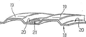
Fig. 7 and 8 partly shows tubulose and strengthens main body 35, it is associated with tyre surface 16 all the time, have basically the 13 measure-alike sizes of measuring of measuring along equidirectional that parallel to the axis with tyre surface 16, and be different from enhancing main body 18 parts and be that it has predetermined minute esd resistance of counter stress, promptly resistance depends on the stress that it suffers.Especially, tubular body 35 comprises continuous outer annular band 36 and by a plurality of 37 with 36 self-supportings.With 36 for flexible and can bear the circumferential tension effect that strengthens on the main body 35 that acts on, and the part 38 that the elastomeric material that preferably includes constitutes and a plurality of enhancing silk or fiber 39, silk or fiber 39 can or can embed in the elastomeric material part 38 without braiding.Extend with 36 whole width along tyre surface 16, integrally be connected to tyre surface 16 self, for example utilize sulphurization or gummed to connect, perhaps adopt the mode that can make that it is dismountable or separate, when tyre surface 16 reaches the limit of wear value, change tyre surface 16 separately so that allow.According to a kind of modification, be with 36 not have elastomeric material part 38, and only comprise the silk or the bar of braiding.
Referring to Fig. 7 and 8, be with 36 supporting piece 38 once more, piece 38 is by sulfuration or only be with 36 by gluing together integrally to be connected to, and stretches to the inside of tire 3, and can produce opposing acts on the circumference compression on the enhancing main body 35 during tire 3 rotates effect.Piece 37 can be made of solid body as shown in Fig. 7 and 8, perhaps as shown in Fig. 9 and 10, constitute by hollow body, be adjacent to each other and alignment so that a plurality of axial row 41 of stop block, promptly be parallel to a plurality of axial row 41 of the axis 13 of tire, and a plurality of circumferential row 42 of piece.Shown in example in, piece 37 has mutually the same size and geometric configuration, and respectively has band quadrangle pedestal in Frusto-conical form, pedestal advantageously is parallel to the axis 13 rectangle of larger skirt.Piece 37 is towards the inside of tire 3 convergent and respectively have accordingly than big base, this pedestal towards with 36 and utilize flexibly connect accordingly part 43 be connected to adjacent block 37 than big base (Fig. 8 and 9).Connecting bridge 43 defines corresponding actual hinge 44, and hinge 44 is hinged on each piece 37 on the piece that is adjacent.In the embodiment shown in Fig. 9 and 10, piece 37 has constituted the part of the cellular main body 45 of the whole flexible thermoplastic material who manufactures with flexibly connecting part 43, and main body 45 is advantageously manufactured by polypropylene or polyamide material.Substituting plot 37 is the solid body of being made by plastics or elastomeric material, and is connected to each other so that limit monolithic integral body.In two kinds of situations, the shape of piece 37 all makes if tire 3 no-loads, and then its sidewall 46 is only adjacent one another are, perhaps is pressed against each other to strengthen main body so that limit prestrain.
In use, when wheel rim 2 transmission is loaded to tire 3, the various piece that strengthens main body 35 according to them with respect to acting on different with position that the area of contact of the area supported of wheel assembly 1 occupies.Especially, in the area of contact of wheel assembly area supported, owing to be passed to the load of tyre surface 16, piece 37 is in opposite sense around the respective axis of pivot and relative to each other rotates (as shown in Fig. 8 a), and defining corresponding V-shaped groove mouth 49 each other, this notch 49 is widened towards the inside of tire 3, and in the zone about described area of contact, they are pressed against each other as shown in Fig. 8 b) so that bear the load that is passed to tire 3 by wheel rim 2.
When wheel assembly runs into (Fig. 7) when being designated as 50 " step ", perhaps when concentrated load when the outside is applied thereto, as shown in Figure 7,44 pairs on actual hinge strengthens main body and applies minimum drag towards tire 2 in-to-in deflections, so that make each piece 37 rotate one another in opposite directions, thereby each other little by little according to proportional separating of distance of itself and step 50, as shown in Figure 7.In this case, in addition, the position is defining one group of V-shaped groove mouth 49 each other near the piece 37 of step 50, can see from Fig. 7 once more, it is variable that it widens situation, and arrive maxim at step 50 places, and value is along with the distance with step 50 self increases and reduces gradually.
For the rotation of confinement block 37, especially under the situation that outstanding step is arranged, part 43 is enhanced part 52 and replaces, as shown in Figure 10.Each part 52 comprises solid tyre bead 52a, and the elastic sidewall 46 of relevant block 37 integrally extends from this tyre bead 52a.In this way, the hinge 44 that is arranged on two reality between the adjacent block 37 in the solution of Fig. 9 is just replaced by the hinge 53 of two reality and 54, they each by a paragraph qualification of the wall of the relevant block 37 adjacent with tyre bead 53.With respect to hinge 44, therefore hinge 53 and 54 moves towards the free end of piece 37, so that make that except the predetermined rotational angular of piece 37, solid tyre bead 52a applies the torque of opposing to make piece 37 rotating opening, thereby the distortion and the tyre surface 16 of restriction enhancing main body 35 are out of shape towards tire 3 in-to-ins.
Should be understood that by the fwd description compare with known solution, described wheel assembly 1 does not at first need pressurization, thereby has solved all functions and the maintenance issues that is associated with the existence of air or another kind of pressure fluid.
In addition, compare with known solution once more, described tire 3,30 has guaranteed best elasticity and the deformability when loading, and has guaranteed the minimizing that lags behind simultaneously.These special characteristics partly derive from the existence of film 24, and partly get the design characteristics of self-reinforcing main body 18 and 37.Under the situation of main body 37, particularly clearly, allow that with piece 37 tire is suitable for different condition of loading and the obstacle that runs into 36 during rolling, thereby different distortion takes place, and according to adapting according to controlled way that it stands.Therefore, even exist under the situation of sizable obstacle, tire still can obtain flow property, therefore obtains high-caliber driving comfort in any case, has identical road hold mode.
In addition, not having pressure fluid to make can provide through hole, and through hole both strengthens main body 18 and 35 by tyre surface 16 and tubulose, again by wheel rim 2, and the wall that in known solution, defines the pressure chamber by wheel rim particularly with tire.In fact, in strengthening the particular case of main body 35, clearly, can obtain through hole by removing one or more 37 or sidewall by smaller base or piece 37 self.
The passage that provides by tyre surface and tubulose enhancing main body 18 is used for double duty.At first, in fact, they allow by the hole in the wheel rim 2 14 to inside tires separately discharging be present in water in tyre surface/interface, road surface, and therefrom to outside drain.Therefore, pass tyre surface 16 and strengthen the passage 20 of main body 18 and 21 the grooving aspect that exists in tyre surface 16 self provides bigger degree of freedom, because having avoided producing conventional interconnection, it come lateral row to discharge water, they are essential in known solution so that obtain the required grasping force on the road surface, but but are N/R sound wave emissions sources.In addition, passage 20 and 21 existence make the efficient and the reliability that can reduce and control the temperature while tire self that uses tire obviously increase.For providing the sealing to hole 20, aerated materials prevented that solid body such as stone, gravel and/or sand from entering in the tire.
The chamber that need not be provided for pressure fluid has also increased the design of wheel rim 2 and the degree of freedom of production, and therefore they can have form and the geometric configuration that the tyre type of present use is not allowed.At last, the bigger degree of freedom of the form of wheel rim comprises weight that significantly reduces wheel assembly and the hysteresis that further reduces wheel assembly self.
Should be understood that by the fwd description, can make the remodeling and the modification of the protection domain that does not deviate from claim described wheel assembly 1.Particularly, can provide diverse ways that tyre bead 8 is connected to wheel rim 2, and other tubular body can be arranged on the inside of main body 18,35 or outside self contact with main body 18,35 or self separate with main body 18,35.
In addition, tubular body 18 and 35 and tyre surface 16 can save corresponding hole 20 and 21, wheel rim can save hole 14, and can comprise other through hole that for example passes flange 6.In addition, when existing, hole 20 and 21 can have and is different from very much size shown in the example and/or geometric configuration, and particularly they can have especially little axial dimension, enter in the tire to prevent external main body.
At last, film 24 can only constitute the centre or the afterbody of corresponding sidewall 15, and perhaps they can have radially variable cross-sectional plane.If film is subjected to prestension, then when " static ", their radial dimension is less than the distance between tyre bead and the tyre surface.
In addition, with regard to main body 35, clearly, piece 37 can have and is different from by described form of example and size, and the distribution of piece 37 also can be different with orientation.Particularly, can provide a plurality of continuous axial segments, they do not parallel to the axis 13, extend and are defining corresponding continuous axial notch each other along the whole width of tyre surface.In addition, in order to be adapted to the specific curvature of tyre surface 16, particularly at the shoulder place of tire, piece 37 can have the different height in each zone, particularly can have the height that reduces near described shoulder.
Claims (45)
1. the tire (3 that is used for vehicle; 30), its have axis of symmetry (13) and comprise a tyre surface (16), two sidewalls (15), two tyre beads (8) and at least one tubulose that are connected on the wheel rim of being made by elastomeric material (2) strengthen main body (18,35), it is coaxial with described axis (13) that this at least one tubulose strengthens main body (18,35), surround by described tyre surface (16), and between described sidewall (15), extend; Each comprises corresponding elastic annular film (24) and straight edge line in the described sidewall, and the axis (13) of this bus and tire (3) forms the angle (A) that is different from 90 degree; It is characterized in that described tubulose strengthens main body (35) and comprises an endless belt (36) and a plurality of (37), these pieces (37) are supported by described endless belt in the position that is adjacent to each other, and during tire self rotates, can be pressed against each other so that the effect that is present in the compression circumference on the tire is applied resistance.
2. tire according to claim 1, what it is characterized in that described tubular body (18,35) is parallel to size that described axis (13) measures measure-alike with the tyre surface of measuring along equidirectional (16) basically.
3. tire according to claim 1 and 2 is characterized in that described tubular body (18,35) has side direction through hole (21).
4. tire according to claim 3 is characterized in that the hole of some described through hole (21) for along the circumferential direction prolonging at least.
5. tire according to claim 3 is characterized in that some described through hole (21) along the circumferential direction is in alignment with each other so that form many circumferencial direction rows' hole at least.
6. tire according to claim 5 is characterized in that described tubular body (18,35) comprises the hole of the described circumferential row that at least one pair of separates each other vertically.
7. tire according to claim 1 and 2 is characterized in that described tubular body (18,35) is by respective cylindrical surperficial limit coaxial with axis (13); At least one described cylindrical surface has a kind of bus, and this bus is straight line and the axis (13) that is parallel to tire (3).
8. tire according to claim 1 and 2 is characterized in that described film (24) made by anisotropic material.
9. tire according to claim 8 is characterized in that described film (24) utilizes fiber reinforcement, and these fiber settings also are oriented and are used for preventing that film is at the loading condition local deformation.
10. tire according to claim 9, it is characterized in that described film (24) is enhanced and be included in dihedron (26) top from one's body tensile stress so that will under the quiescent load situation, be present in film (24), this dihedron (26) is tangent with tyre bead (8), has the top of parallel to the axis (13).
11. tire according to claim 1 and 2 is characterized in that the bus of described film (24) is assembled toward each other so that join at the exterior point of tyre surface (16) place.
12. tire according to claim 1 and 2 is characterized in that the bus of described film (24) is assembled toward each other so that join at tire (3) in-to-in point place.
13. tire according to claim 1 and 2 is characterized in that described film (24) has radially unmodified cross-sectional plane basically.
14. tire according to claim 13 is characterized in that described cross-sectional plane is the cross-sectional plane of substantial rectangular.
15. tire according to claim 1 and 2 is characterized in that described tyre bead (8) comprises at least one circular protrusion (9), this at least one circular protrusion (9) can engage with corresponding keep (7) when being installed in wheel rim (2) and going up.
16. tire according to claim 1 and 2 is characterized in that described tyre surface (16) comprises a plurality of holes (20) of being communicated with inside tires of being used for; Described hole (20) is arranged to corresponding with the hole (21) of the equal amount that passes described tubular body (18,35).
17. tire according to claim 16 is characterized in that described hole utilizes permeable material sealing, and can prevent that external main body from entering in the tire.
18. tire according to claim 17 is characterized in that described permeable material is an aerated materials.
19., it is characterized in that described tyre surface (16) cures on an outside face of described tubular body (18,35) according to aforementioned claim 1 or 2 described tires.
20. tire according to claim 1 and 2 is characterized in that described tyre surface (16) comprises a plurality of exterior periphery grooves (22), and described groove (22) is by a plurality of radial passages (20, the 21) internal communication with tire.
21. tire according to claim 1 and 2, it is characterized in that described film (24) is radially stretched between described tyre surface and described tyre bead (8) in case under the situation that does not have load on the tire by prestension.
22. tire according to claim 1 and 2 is characterized in that described film (24) made by the elastomeric material of homogeneous.
23. tire according to claim 22 is characterized in that described homogeneous material is an isotropic material.
24. tire according to claim 22 is characterized in that described film (24) made by poly-butadiene rubber.
25. tire according to claim 22 is characterized in that described film (24) made by polyisoprene rubber.
26. tire according to claim 22, the material that it is characterized in that manufacturing described film (24) comprises the condensation polymer of the pure and mild derivant of dimethyl silane, and wherein methyl group unit is replaced by vinyl or phenol unit.
27. tire according to claim 1 and 2 is characterized in that described (37) are outstanding towards inside tires from described endless belt (36).
28. tire according to claim 1 and 2 is characterized in that described endless belt (36) comprises a plurality of enhancing silks or bar (39).
29. tire according to claim 28 is characterized in that described endless belt (36) integrally is connected to described tyre surface (16).
30. tire according to claim 28 is characterized in that the mode that described tyre surface is connected to described endless belt (36) makes that it can be released, so that it can be replaced when arriving wear limit.
31. tire according to claim 29 is characterized in that described endless belt (36) is adhered on the described tyre surface (16).
32. tire according to claim 1 and 2 is characterized in that described (37) are tapered towards the inside of tire.
33. tire according to claim 32 is characterized in that described (37) are defining notch (49) each other, these notches (49) extend along the direction that is arranged essentially parallel to described axle (13).
34. tire according to claim 32 is characterized in that described (37) are scattered in a plurality of a plurality of axial row (41) and a plurality of circumferential row (42) that are parallel to described axis (13) of formation.
35. tire according to claim 32 is characterized in that described (37) are connected to each other by relative head (43,52), these can allow that relative to head (43,52) piece (37) relative to each other moves during tire (3) rotates.
36. tire according to claim 35 is characterized in that described relative head is actual hinge (44,53,54).
37. tire according to claim 36 is characterized in that described (37) are connected to each other by connecting bridge (43), these connecting bridges (43) define described relative head; Described (37) and described connecting bridge have constituted the part of the cellular main body of the whole flexible thermoplastic material who manufactures (45).
38. tire according to claim 36 is characterized in that it comprises solid tyre bead (52a), this installs during tyre rotation, can apply the effect of the effect of the relative displacement of opposing generation described (37).
39., it is characterized in that described solid tyre bead (52a) inserts between band (36) and the piece (37) according to the described tire of claim 38.
40. tire according to claim 1 and 2 is characterized in that described (37) are solid body.
41. tire according to claim 1 and 2 is characterized in that described (37) are hollow body.
42., it is characterized in that described tubulose strengthens main body (35) and has cellulated structure according to the described tire of claim 41.
43., it is characterized in that described (37) integrally are connected on the described band (36) by gummed or sulfuration according to the described tire of claim 38.
44. be used for the wheel rim (2) of vehicle, comprise inside part (5), two outstanding and supporting respective seat (7) so that regulate the annular radial part (6) of respective bead (8) from described inside part (5), with the tire of producing according to claim 1 (3), and wall (12), the axis (13) of wall (12) and wheel rim (2) extends between described annulus (6) coaxially, and, it is characterized in that described wall (12) comprises a plurality of through holes of for good and all opening (14) in use towards described tire (3).
45., it is characterized in that it comprises the annulus (31) coaxial and that made by elastomeric material with described axis (13) according to the described wheel rim of claim 44; Described annulus (31) defines the used radial support hill holder of described tyre surface (16).
Applications Claiming Priority (2)
| Application Number | Priority Date | Filing Date | Title |
|---|---|---|---|
| IT000120A ITTO20040120A1 (en) | 2004-02-27 | 2004-02-27 | TIRE FOR VEHICLES, IN PARTICULAR, VEHICLES |
| ITTO2004A000120 | 2004-02-27 |
Related Child Applications (1)
| Application Number | Title | Priority Date | Filing Date |
|---|---|---|---|
| CN2009101421153A Division CN101654043B (en) | 2004-02-27 | 2004-06-15 | Tyre for vehicles |
Publications (2)
| Publication Number | Publication Date |
|---|---|
| CN1922039A CN1922039A (en) | 2007-02-28 |
| CN100554006C true CN100554006C (en) | 2009-10-28 |
Family
ID=34897824
Family Applications (2)
| Application Number | Title | Priority Date | Filing Date |
|---|---|---|---|
| CNB2004800421772A Expired - Fee Related CN100554006C (en) | 2004-02-27 | 2004-06-15 | The tire that is used for vehicle |
| CN2009101421153A Expired - Fee Related CN101654043B (en) | 2004-02-27 | 2004-06-15 | Tyre for vehicles |
Family Applications After (1)
| Application Number | Title | Priority Date | Filing Date |
|---|---|---|---|
| CN2009101421153A Expired - Fee Related CN101654043B (en) | 2004-02-27 | 2004-06-15 | Tyre for vehicles |
Country Status (11)
| Country | Link |
|---|---|
| US (3) | US20080257463A1 (en) |
| EP (2) | EP2062749B1 (en) |
| JP (2) | JP4553935B2 (en) |
| CN (2) | CN100554006C (en) |
| AT (2) | ATE495030T1 (en) |
| BR (1) | BRPI0418594A (en) |
| DE (2) | DE602004031060D1 (en) |
| ES (2) | ES2324039T3 (en) |
| IT (1) | ITTO20040120A1 (en) |
| RU (2) | RU2471638C2 (en) |
| WO (1) | WO2005082643A1 (en) |
Families Citing this family (22)
| Publication number | Priority date | Publication date | Assignee | Title |
|---|---|---|---|---|
| JP5066844B2 (en) * | 2006-06-19 | 2012-11-07 | 横浜ゴム株式会社 | Non pneumatic tire |
| US8196625B1 (en) * | 2006-08-08 | 2012-06-12 | Brant Chenoweth | Supplemental tread tire bead lock |
| JP3952211B1 (en) * | 2006-08-11 | 2007-08-01 | 横浜ゴム株式会社 | Non pneumatic tire |
| WO2010049963A1 (en) * | 2008-10-31 | 2010-05-06 | Fiat Group Automobiles S.P.A. | Airless tire for vehicles, in particular motor vehicles |
| JP4803318B1 (en) * | 2010-12-02 | 2011-10-26 | 横浜ゴム株式会社 | Pneumatic tire |
| CN103287212A (en) * | 2012-03-05 | 2013-09-11 | 蔡志忠 | Wheel with solid tyre |
| CN102673317A (en) * | 2012-05-30 | 2012-09-19 | 史中河 | Novel inflation-free tire |
| BR112015016687B1 (en) | 2013-03-06 | 2021-06-22 | Gatekeeper Systems, Inc | WHEEL FOR TROLLEY POWERED BY BEING HUMAN AND ITS MANUFACTURING METHOD |
| EP3007909A4 (en) | 2013-06-15 | 2017-03-01 | Ronald Thompson | Annular ring and non-pneumatic tire |
| EP3237229B1 (en) * | 2014-12-22 | 2020-11-18 | Bridgestone Americas Tire Operations, LLC | Tire and wheel assembly having angled interfaces |
| WO2016120872A1 (en) * | 2015-01-29 | 2016-08-04 | Alliance Tire Co. Ltd | A laterally stable pneumatic tire |
| CA2976055A1 (en) | 2015-02-04 | 2016-08-11 | Advancing Mobility, Llc. | Non-pneumatic tire and other annular devices |
| JP6645105B2 (en) * | 2015-10-06 | 2020-02-12 | 住友ゴム工業株式会社 | Non-pneumatic tire |
| JP6558201B2 (en) * | 2015-10-19 | 2019-08-14 | 住友ゴム工業株式会社 | Airless tire |
| US9834040B2 (en) * | 2015-12-10 | 2017-12-05 | The Goodyear Tire & Rubber Company | Structurally supported tire |
| US10639934B2 (en) * | 2016-11-22 | 2020-05-05 | The Goodyear Tire & Rubber Company | Shear band for a structurally supported tire |
| EP3768525B1 (en) * | 2018-03-23 | 2022-10-19 | Trelleborg Wheel Systems Italia S.p.A. | Solid tyre provided with cushioning holes, |
| JP2020006804A (en) * | 2018-07-09 | 2020-01-16 | 本田技研工業株式会社 | Vehicular wheel |
| GB2587247B (en) * | 2020-01-24 | 2021-10-06 | Tree Ass Ltd | Tyre |
| CN112223958B (en) * | 2020-10-26 | 2022-07-29 | 吉林工程技术师范学院 | Bionic mechanism explosion-proof bicycle tire and preparation method thereof |
| CN114604041A (en) * | 2020-12-09 | 2022-06-10 | 北京橡胶工业研究设计院有限公司 | Tire bead locking ring for preventing tire from knocking off |
| KR102485920B1 (en) * | 2021-01-06 | 2023-01-10 | 한국기계연구원 | Wheel unit having complex structure |
Citations (2)
| Publication number | Priority date | Publication date | Assignee | Title |
|---|---|---|---|---|
| US4170254A (en) * | 1974-08-23 | 1979-10-09 | Dunlop Limited | Tire with a straight sidewall |
| US4241775A (en) * | 1977-08-25 | 1980-12-30 | Dunlop Limited | Tires |
Family Cites Families (25)
| Publication number | Priority date | Publication date | Assignee | Title |
|---|---|---|---|---|
| JPS521522B1 (en) * | 1971-06-12 | 1977-01-14 | ||
| DE2348038A1 (en) * | 1973-09-24 | 1975-04-03 | Continental Gummi Werke Ag | Vehicle pneumatic tyre with convergingly inclined sidewalls - which bend inwards when load is applied to the tyre |
| GB1514474A (en) * | 1974-08-23 | 1978-06-14 | Dunlop Ltd | Tyre and wheel assemblies |
| JPS51151901A (en) * | 1975-06-20 | 1976-12-27 | Bridgestone Corp | Pneumatic safty tire |
| PL112739B1 (en) * | 1976-05-04 | 1980-10-31 | Polyair Maschinenbau Gmbh | Cellular tyre |
| JPS531135A (en) * | 1976-06-25 | 1978-01-07 | Nissan Motor | Partial plating method of plastics |
| JPS53503A (en) * | 1976-06-25 | 1978-01-06 | Bridgestone Corp | Puncture-proof pueumatic tyre |
| JPS5914364B2 (en) * | 1980-04-07 | 1984-04-04 | 住友ゴム工業株式会社 | Spikes for snow tires |
| JPS58183303A (en) * | 1982-04-22 | 1983-10-26 | Gengo Kondou | Tire having plurality of functions |
| US4664166A (en) * | 1982-07-16 | 1987-05-12 | Julien Benisti | Non slip system for a deformable driving band |
| US4456048A (en) * | 1983-01-24 | 1984-06-26 | Grumman Aerospace Corporation | Dual-modulus band banded tire |
| JPS59199301A (en) * | 1983-04-26 | 1984-11-12 | ル−ロン・アラベ・ウイリアムス | Self-cooling, airless and shock absorbing wheel for vehicle and tire thereof |
| AT386571B (en) * | 1985-12-11 | 1988-09-12 | Semperit Ag | VEHICLE TIRES |
| DE3604023A1 (en) * | 1986-02-08 | 1987-08-13 | Continental Gummi Werke Ag | Method and device for measuring the concentricity of a pneumatic vehicle tyre |
| US5050656A (en) * | 1990-04-23 | 1991-09-24 | The B. F. Goodrich Company | Non-pneumatic tire wheel |
| JPH0532006U (en) * | 1991-10-14 | 1993-04-27 | 基雄 根井 | Belt pulley attached to automobile tire |
| DE4207613A1 (en) * | 1992-03-10 | 1993-09-16 | Hans Scheibenpflug | Tyre fitted with withdrawable spikes in tread - has internal diaphragm which is cured circumferentially inside shoulder and can be pressurised to force spikes out through holes in tread |
| JPH0899508A (en) * | 1994-09-30 | 1996-04-16 | Bridgestone Corp | Pneumatic tire |
| US6923233B1 (en) * | 1999-09-30 | 2005-08-02 | The Goodyear Tire & Rubber Company | Runflat tire with sawtooth shaped insert |
| PL356125A1 (en) * | 1999-12-10 | 2004-06-14 | Michelin Recherche Et Technique S.A. | Structurally supported resilient tire |
| ATE290565T1 (en) * | 2000-02-24 | 2005-03-15 | Michelin Soc Tech | VULCANIZABLE RUBBER MIXTURE FOR PRODUCING A Pneumatic TIRE AND Pneumatic TIRE CONTAINING SUCH A COMPOSITION |
| JP4490561B2 (en) * | 2000-07-14 | 2010-06-30 | 住友ゴム工業株式会社 | Pneumatic tire |
| JP4614622B2 (en) * | 2001-04-16 | 2011-01-19 | ミシュラン ルシェルシュ エ テクニーク ソシエテ アノニム | Structurally supported elastic tire with bias ply carcass |
| WO2003018332A1 (en) * | 2001-08-24 | 2003-03-06 | Societe De Technologie Michelin | Non-pneumatic tire |
| FR2839015A1 (en) * | 2002-04-29 | 2003-10-31 | Conception & Dev Michelin Sa | Flexible non-pneumatic tire comprising a series of articulated joints between supporting elements and interconnecting structure |
-
2004
- 2004-02-27 IT IT000120A patent/ITTO20040120A1/en unknown
- 2004-06-15 EP EP09150804A patent/EP2062749B1/en not_active Not-in-force
- 2004-06-15 CN CNB2004800421772A patent/CN100554006C/en not_active Expired - Fee Related
- 2004-06-15 US US10/590,988 patent/US20080257463A1/en not_active Abandoned
- 2004-06-15 WO PCT/IT2004/000347 patent/WO2005082643A1/en active Application Filing
- 2004-06-15 EP EP04736876A patent/EP1720719B1/en not_active Not-in-force
- 2004-06-15 DE DE602004031060T patent/DE602004031060D1/en active Active
- 2004-06-15 AT AT09150804T patent/ATE495030T1/en not_active IP Right Cessation
- 2004-06-15 JP JP2007500355A patent/JP4553935B2/en not_active Expired - Fee Related
- 2004-06-15 BR BRPI0418594-3A patent/BRPI0418594A/en not_active IP Right Cessation
- 2004-06-15 RU RU2008132423/11A patent/RU2471638C2/en not_active IP Right Cessation
- 2004-06-15 ES ES04736876T patent/ES2324039T3/en active Active
- 2004-06-15 AT AT04736876T patent/ATE430661T1/en not_active IP Right Cessation
- 2004-06-15 CN CN2009101421153A patent/CN101654043B/en not_active Expired - Fee Related
- 2004-06-15 DE DE602004021036T patent/DE602004021036D1/en active Active
- 2004-06-15 US US10/591,017 patent/US7950429B2/en not_active Expired - Fee Related
- 2004-06-15 ES ES09150804T patent/ES2359040T3/en active Active
- 2004-06-15 RU RU2006132456/11A patent/RU2344944C2/en not_active IP Right Cessation
-
2009
- 2009-05-20 JP JP2009121524A patent/JP4860721B2/en not_active Expired - Fee Related
-
2011
- 2011-04-22 US US13/092,768 patent/US8720505B2/en active Active
Patent Citations (2)
| Publication number | Priority date | Publication date | Assignee | Title |
|---|---|---|---|---|
| US4170254A (en) * | 1974-08-23 | 1979-10-09 | Dunlop Limited | Tire with a straight sidewall |
| US4241775A (en) * | 1977-08-25 | 1980-12-30 | Dunlop Limited | Tires |
Also Published As
| Publication number | Publication date |
|---|---|
| EP1720719A1 (en) | 2006-11-15 |
| EP1720719B1 (en) | 2009-05-06 |
| CN101654043A (en) | 2010-02-24 |
| DE602004021036D1 (en) | 2009-06-18 |
| RU2008132423A (en) | 2010-02-20 |
| US8720505B2 (en) | 2014-05-13 |
| JP2007525361A (en) | 2007-09-06 |
| EP2062749B1 (en) | 2011-01-12 |
| ATE495030T1 (en) | 2011-01-15 |
| US20110192515A1 (en) | 2011-08-11 |
| RU2006132456A (en) | 2008-04-10 |
| EP2062749A1 (en) | 2009-05-27 |
| US7950429B2 (en) | 2011-05-31 |
| ES2359040T3 (en) | 2011-05-17 |
| JP4860721B2 (en) | 2012-01-25 |
| ATE430661T1 (en) | 2009-05-15 |
| DE602004031060D1 (en) | 2011-02-24 |
| RU2344944C2 (en) | 2009-01-27 |
| RU2471638C2 (en) | 2013-01-10 |
| BRPI0418594A (en) | 2008-01-29 |
| US20070261774A1 (en) | 2007-11-15 |
| ITTO20040120A1 (en) | 2004-05-27 |
| WO2005082643A1 (en) | 2005-09-09 |
| ES2324039T3 (en) | 2009-07-29 |
| CN1922039A (en) | 2007-02-28 |
| JP4553935B2 (en) | 2010-09-29 |
| JP2009179320A (en) | 2009-08-13 |
| US20080257463A1 (en) | 2008-10-23 |
| CN101654043B (en) | 2012-09-05 |
Similar Documents
| Publication | Publication Date | Title |
|---|---|---|
| CN100554006C (en) | The tire that is used for vehicle | |
| US11590800B2 (en) | Non-pneumatic tire | |
| CA2865520C (en) | Non-pneumatic tire | |
| AU2011266952B2 (en) | Non- pneumatic tire | |
| EA035298B1 (en) | Airless tyre for vehicles | |
| US11235616B2 (en) | Method of mounting a non-pneumatic tire onto a hub | |
| US11312179B2 (en) | Non-pneumatic wheel and method of mounting non-pneumatic tire | |
| US20160167465A1 (en) | On-wheel air maintenance system | |
| CN101314315A (en) | Non-inflatable vehicle tyre | |
| US11827062B2 (en) | Non-pneumatic tire with a flexible looped spoke and method of forming | |
| CN107031318B (en) | Air on wheel maintains system | |
| WO2009057780A1 (en) | Pneumatic radial tire | |
| RU2380238C2 (en) | Device to support tire in blowing off and tire assembled with such device | |
| US10189320B2 (en) | On-wheel air maintenance system | |
| RU2363593C1 (en) | Vehicle wheel tire with adjustable road-holding | |
| US20160280015A1 (en) | Two or more piece bead lock systems for tube and tubeless tyres |
Legal Events
| Date | Code | Title | Description |
|---|---|---|---|
| C06 | Publication | ||
| PB01 | Publication | ||
| C10 | Entry into substantive examination | ||
| SE01 | Entry into force of request for substantive examination | ||
| C14 | Grant of patent or utility model | ||
| GR01 | Patent grant | ||
| C17 | Cessation of patent right | ||
| CF01 | Termination of patent right due to non-payment of annual fee |
Granted publication date: 20091028 Termination date: 20120615 |