CN100548793C - Bicycle shift control device with light structures - Google Patents
Bicycle shift control device with light structures Download PDFInfo
- Publication number
- CN100548793C CN100548793C CNB2007100858436A CN200710085843A CN100548793C CN 100548793 C CN100548793 C CN 100548793C CN B2007100858436 A CNB2007100858436 A CN B2007100858436A CN 200710085843 A CN200710085843 A CN 200710085843A CN 100548793 C CN100548793 C CN 100548793C
- Authority
- CN
- China
- Prior art keywords
- bicycle
- light
- indicating device
- pattern indicating
- shift pattern
- Prior art date
- Legal status (The legal status is an assumption and is not a legal conclusion. Google has not performed a legal analysis and makes no representation as to the accuracy of the status listed.)
- Active
Links
Images


Classifications
-
- B—PERFORMING OPERATIONS; TRANSPORTING
- B62—LAND VEHICLES FOR TRAVELLING OTHERWISE THAN ON RAILS
- B62M—RIDER PROPULSION OF WHEELED VEHICLES OR SLEDGES; POWERED PROPULSION OF SLEDGES OR SINGLE-TRACK CYCLES; TRANSMISSIONS SPECIALLY ADAPTED FOR SUCH VEHICLES
- B62M25/00—Actuators for gearing speed-change mechanisms specially adapted for cycles
-
- B—PERFORMING OPERATIONS; TRANSPORTING
- B60—VEHICLES IN GENERAL
- B60Q—ARRANGEMENT OF SIGNALLING OR LIGHTING DEVICES, THE MOUNTING OR SUPPORTING THEREOF OR CIRCUITS THEREFOR, FOR VEHICLES IN GENERAL
- B60Q3/00—Arrangement of lighting devices for vehicle interiors; Lighting devices specially adapted for vehicle interiors
- B60Q3/20—Arrangement of lighting devices for vehicle interiors; Lighting devices specially adapted for vehicle interiors for lighting specific fittings of passenger or driving compartments; mounted on specific fittings of passenger or driving compartments
- B60Q3/283—Steering wheels; Gear levers
-
- B—PERFORMING OPERATIONS; TRANSPORTING
- B62—LAND VEHICLES FOR TRAVELLING OTHERWISE THAN ON RAILS
- B62J—CYCLE SADDLES OR SEATS; AUXILIARY DEVICES OR ACCESSORIES SPECIALLY ADAPTED TO CYCLES AND NOT OTHERWISE PROVIDED FOR, e.g. ARTICLE CARRIERS OR CYCLE PROTECTORS
- B62J6/00—Arrangement of optical signalling or lighting devices on cycles; Mounting or supporting thereof; Circuits therefor
- B62J6/22—Warning or information lights
- B62J6/24—Warning or information lights warning or informing the rider, e.g. low fuel warning lights
-
- B—PERFORMING OPERATIONS; TRANSPORTING
- B62—LAND VEHICLES FOR TRAVELLING OTHERWISE THAN ON RAILS
- B62K—CYCLES; CYCLE FRAMES; CYCLE STEERING DEVICES; RIDER-OPERATED TERMINAL CONTROLS SPECIALLY ADAPTED FOR CYCLES; CYCLE AXLE SUSPENSIONS; CYCLE SIDE-CARS, FORECARS, OR THE LIKE
- B62K23/00—Rider-operated controls specially adapted for cycles, i.e. means for initiating control operations, e.g. levers, grips
- B62K23/02—Rider-operated controls specially adapted for cycles, i.e. means for initiating control operations, e.g. levers, grips hand actuated
-
- B—PERFORMING OPERATIONS; TRANSPORTING
- B62—LAND VEHICLES FOR TRAVELLING OTHERWISE THAN ON RAILS
- B62M—RIDER PROPULSION OF WHEELED VEHICLES OR SLEDGES; POWERED PROPULSION OF SLEDGES OR SINGLE-TRACK CYCLES; TRANSMISSIONS SPECIALLY ADAPTED FOR SUCH VEHICLES
- B62M25/00—Actuators for gearing speed-change mechanisms specially adapted for cycles
- B62M2025/003—Actuators for gearing speed-change mechanisms specially adapted for cycles with gear indicating means, e.g. a display
-
- Y—GENERAL TAGGING OF NEW TECHNOLOGICAL DEVELOPMENTS; GENERAL TAGGING OF CROSS-SECTIONAL TECHNOLOGIES SPANNING OVER SEVERAL SECTIONS OF THE IPC; TECHNICAL SUBJECTS COVERED BY FORMER USPC CROSS-REFERENCE ART COLLECTIONS [XRACs] AND DIGESTS
- Y10—TECHNICAL SUBJECTS COVERED BY FORMER USPC
- Y10S—TECHNICAL SUBJECTS COVERED BY FORMER USPC CROSS-REFERENCE ART COLLECTIONS [XRACs] AND DIGESTS
- Y10S116/00—Signals and indicators
- Y10S116/05—Signals and indicators using light guides
-
- Y—GENERAL TAGGING OF NEW TECHNOLOGICAL DEVELOPMENTS; GENERAL TAGGING OF CROSS-SECTIONAL TECHNOLOGIES SPANNING OVER SEVERAL SECTIONS OF THE IPC; TECHNICAL SUBJECTS COVERED BY FORMER USPC CROSS-REFERENCE ART COLLECTIONS [XRACs] AND DIGESTS
- Y10—TECHNICAL SUBJECTS COVERED BY FORMER USPC
- Y10T—TECHNICAL SUBJECTS COVERED BY FORMER US CLASSIFICATION
- Y10T74/00—Machine element or mechanism
- Y10T74/20—Control lever and linkage systems
- Y10T74/20396—Hand operated
- Y10T74/20402—Flexible transmitter [e.g., Bowden cable]
- Y10T74/2042—Flexible transmitter [e.g., Bowden cable] and hand operator
- Y10T74/20438—Single rotatable lever [e.g., for bicycle brake or derailleur]
Landscapes
- Engineering & Computer Science (AREA)
- Mechanical Engineering (AREA)
- Chemical & Material Sciences (AREA)
- Combustion & Propulsion (AREA)
- Transportation (AREA)
- Control Of Transmission Device (AREA)
- Lighting Device Outwards From Vehicle And Optical Signal (AREA)
- Non-Portable Lighting Devices Or Systems Thereof (AREA)
- Arrangement And Mounting Of Devices That Control Transmission Of Motive Force (AREA)
Abstract
A kind of bicycle shift control device comprises speed change gear shell, variable speed control mechanism and bicycle light structure.Variable speed control mechanism is connected on the speed change gear shell.Variable speed control mechanism is able to configured and disposed with the control bicycle transmission part.Bicycle light structure is connected on the speed change gear shell.Bicycle light structure be set up and be constructed so that the bicycle positioning lamp on away from the primary importance of drive range indicating device from the outside most of light that throwed by the bicycle positioning lamp of projection of speed change gear shell, and the fraction light that projection is throwed by the bicycle positioning lamp on away from the second place of described primary importance is to illuminate the drive range indicating device.
Description
Technical field
The present invention generally relates to a kind of bicycle shift control device with light structures.More particularly, the present invention relates to the shift pattern indicating device that both can be with light structures provides illumination also can provide illumination to be used for the bicycle shift control device of night visibility.
Background technology
Just becoming more popular pastime mode in the time of by bike as transportation means.In addition, concerning amateur and professional athlete, all become popular athletics sports campaign by bike.No matter bicycle is to be used for pastime, and transportation is sports still, and bicycle industry is improving bicycle always.Especially, bicycle industry is constantly improving the overall performance of bicycle, also has user's affinity and overall security simultaneously.
Usually bicycle is provided with parasite on diverse location, so night bicycle be appreciiable to power actuated vehicle.Be placed on the diverse location of bicycle these parasite strategies, for example in front, in the back, on foot-operated and on wheel at a plurality of direction reflected light rayss.So, the bicycle of band parasite can be seen by power actuated vehicle usually at night.Yet recently, some bicycles are for being provided with and using electrically operated car light through the night cyclist by bike of being everlasting.
When providing car light on bicycle, car light is usually by electrical generator and/or powered battery on the moveable part that is configured in bicycle (for example one of them wheel).These car lights can be set to glisten off and on or be used for throwing light on constantly.For example, the cyclist often uses the red back car light of optional flash of light and the white front car light that continues to illuminate.This is and power actuated vehicle car light similar design.Front car light is commonly used to illuminate the road in cyclist the place ahead, also makes power actuated vehicle notice the existence and the fwd position of bicycle simultaneously.Back car light is commonly used to make power actuated vehicle to notice the existence of bicycle and the position of back.Front car light and back car light are used for making power actuated vehicle to notice the orientation and the moving direction of bicycle jointly.
Though the existing system of these parasites and/or car light runs well usually and make bicycle use in comparatively safe by bike the time at night, they are perplexed by defective also.Especially, these existing systems may be big relatively, heavy and/or inconvenient.And these existing systems may be relatively not attractive on aesthetic.In addition, these existing systems may be relatively costly and/or structure difficulty and complicated.Therefore, the existing system of these parasites may be unpractical concerning some cyclist.Some cyclist also seldom night by bike.These cyclists may think that parasite and/or car light are unnecessary, and therefore remove such project from their bicycle.If night by bike, then remove parasite and reduced the visbility of bicycle other vehicle from bicycle.Even the cyclist do not plan night by bike, need also may take place in situation by bike at night.
And, at night by bike the time, the unusual difficulty of observation display and/or shift pattern indicating device concerning the cyclist.Some bicycle computer has and comprises display member or the panel that is used for illuminating display pannel or member in the time at night.Usually, the cyclist presses the button that triggers car light.In case cyclist's release button, light just extinguishes.A shortcoming of such device is, for the information cyclist on the observation display must carry out action respectively.And the common inefficiency of car light also causes very big loss in the battery used life.In addition, may unexpectedly meet these buttons not needing to use in the time on daytime of battery.In any case the gear shift indicating device especially lacks any illumination that they are seen at night that in fact may make usually with the mechanical gear shift indicating device.
Based on above viewpoint, concerning those skilled in the art, obviously, be necessary to exist the bicycle shift control device with light structures of improvement.The present invention proposes this demand in this area, will be conspicuous other demand concerning those skilled in the art from this disclosure in addition simultaneously.
Summary of the invention
An object of the present invention is to provide the bicycle shift controller of band light structures, this light structures provide position or positioning lamp (for example visbility lamp) in case night bicycle be appreciiable to other vehicle.
Another object of the present invention provides the bicycle shift control device that has when the light structures of shift pattern indicating device illumination was provided by bike the time at night.
Another object of the present invention provides and has and can the bicycle shift control device that pleasant mode is arranged on the light structures on the bicycle with complete, aesthetic in addition.
Also have another object of the present invention in addition to provide and have manufacturings, assembling and construct the bicycle shift control device of relative simple and cheap light structures.
Can reach aforesaid purpose basically by the bicycle shift control device with the light structures that comprises speed change gear shell, variable speed control mechanism and bicycle light structure is provided.Variable speed control mechanism is connected on the speed change gear shell.Configured and disposed variable speed control mechanism is with the control bicycle transmission part.Bicycle light structure is connected on the speed change gear shell.Bicycle light structure comprises the bicycle positioning lamp, bicycle light structure be set up and be constructed so that the bicycle positioning lamp on away from the primary importance of shift pattern indicating device from the outside most of light that throwed by the bicycle positioning lamp of projection of speed change gear shell, and the fraction light that projection is throwed by the bicycle positioning lamp on away from the second place of described primary importance is to illuminate the shift pattern indicating device.
Combine with accompanying drawing the detailed description that discloses the preferred embodiments of the present invention from following, these and other purpose of the present invention, feature, viewpoint and advantage will be conspicuous concerning those skilled in the art.
Description of drawings
With reference now to this original specification sheets part of composition, accompanying drawing:
Fig. 1 is the lateral elevational view that is equipped with the bicycle of the speed-change control device with light structures according to the present invention;
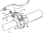
Fig. 2 is the enlarged perspective of the speed-change control device with light structures of example in Fig. 1;
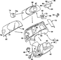
Fig. 3 is the amplification decomposition diagram of the speed-change control device with light structures of example in Fig. 2;
Fig. 4 is the decomposition diagram of the speed-change control device with light structures of example in Fig. 2;
Fig. 5 is the amplification plan view of the speed-change control device with light structures of example in Fig. 2-4;
Fig. 6 be in Fig. 2-5 example have the partial section of the speed-change control device of light structures along the section line 6-6 appreciiable of Fig. 5;
Fig. 7 is the cross-sectional of the speed-change control device with light structures of example in Fig. 2-6;
Fig. 8 is in the amplification, decomposition of the lid member of the speed-change control device with light structures of example in Fig. 2-6 and parasite/side perspective view;
Fig. 9 is through the lid member of the speed-change control device with light structures of giving an example in Fig. 8 after the partial assembled and the following/side perspective view of parasite;
Figure 10 is the amplification of installation cover member and parasite, down local/side perspective view in Fig. 8 and 9, the status indicator lens lid that has the light guide that is connected to the there and be connected to the there partly;
Figure 11 is the following/side perspective view of mounting structure among Figure 10, has the printed circuit board (PCB) that is connected the there partly;
Figure 12 is the preceding/side perspective view of mounting structure among Figure 11, has the LED lens that are connected the there partly;
Figure 13 is the following/side perspective view of the part of mounting structure among Figure 12, has the lid lens that are connected the there partly; And
Figure 14 is connected to the substrate of speed-change control device partly or the following/side perspective view of mounting structure is installed among Figure 13 on the bracket.
The specific embodiment
Referring now to illustrating embodiment chosen of the present invention.Will be apparent concerning those skilled in the art, the description that the following embodiment of the invention is provided only is to be used to illustrate rather than is in order to limit purpose of the present invention as being limited by bonded assembly rights statement and its equivalence.
Please initial reference Fig. 1, first embodiment according to the invention has shown the bicycle 10 with speed-change control device 12.According to the present invention, speed-change control device 12 is provided with light structures 24, is provided with and constructs so that it is from bicycle 10 outside projecting beams (promptly on direction fully forward).According to the present invention, also configured and disposed light structures 24 is with at the shift pattern indicating device 26 that illuminates speed-change control device 12 away from the position of the light beam that projects from bicycle 10.
Bicycle and its various parts such as bicycle 10 are known in this area.Therefore, bicycle 10 comprises the conventional vehicle frame 11 that revolves a front fork that has, and also has such as preceding and rear wheel 13a and 13b, Front Derailleur (derailleur) 15, Rear Derailleur 16, front crankshaft FC, back boxlike RC, chain C with flywheel (not shown), preceding and back disc- brake 17a and 17b equally, rides, the various conventional bicycle assembly parts of vehicle seat and be connected to other conventional components of vehicle frame 11 in the mode of routine.Unless relate to the present invention, bicycle 10 and its various parts will be not can at length not discussed and/or show at this.In other words, only speed-change control device 12 will be in this discussion and/or demonstration with the parts that relate to the bicycle 10 of speed-change control device 12 of the present invention.
With reference now to Fig. 1 and 2,, speed-change control device 12 is connected on the handlebar 14 of bicycle 10 in the mode of routine.Handlebar 14 is connected on the front fork of vehicle frame 11 in a usual manner.Speed-change control device 12 effectively is connected to Rear Derailleur 16 (being bicycle transmission part) moving with control Rear Derailleur 16 by variable speed control cable 18 in a usual manner.In order to produce light structures 24 power supplies of electric current to give speed-change control device 12 of the present invention, at least one comprises conventional wheel hub electrical generator among preferred wheel 13a and the 13b.Particularly, preferred front vehicle wheel 13a is included in the wheel hub electrical generator HD that produces the routine of electric current in the front vehicle wheel 13a rotary course.Wheel hub electrical generator HD is electrically connected to light structures 24 by electric wire 19, is described in more detail following.
Apparent concerning those skilled in the art, if necessary and/or required, can not break away from the present invention bicycle 10 and its conventional components are carried out various modifications.In other words, apparent concerning those skilled in the art, if necessary and/or required, can not only be used in combination but also can on a plurality of dissimilar bicycles, be used in combination with the bicycle assembly parts of a plurality of routines according to speed-change control device 12 of the present invention.For example, apparent concerning those skilled in the art, if necessary and/or required, the light structures 24 of speed-change control device 12 of the present invention can be by the power supply power supply that is applicable to any conventional on the bicycle (for example battery and/or alternative electrical generator etc.).
With reference now to Fig. 1-5,, speed-change control device 12 comprises speed change gear (shifter) shell 20, variable speed control mechanism 22, light structures 24, shift pattern indicating device 26 and user's control member 28 substantially.Speed change gear shell 20 is configured on the handlebar 14 regularly in the mode of routine.Between speed change gear shell 20 and user's control member 28, support variable speed control mechanism 22 and shift pattern indicating device 26 movably.According to the present invention, light structures 24 immovably is configured on the speed change gear shell 20.Speed change gear shell 20 supports user's control member 28 movably relatively.
Variable speed control mechanism 22 is placed in speed change gear shell 20 and the user's control member 28 partly.Variable speed control mechanism 22 is operably connected on user's control member 28 to move corresponding to moving of user's control member 28.Shift pattern indicating device 26 is placed in the speed change gear shell 20.Configured and disposed shift pattern indicating device 26 makes its moving to move relative to speed change gear shell 20 in response to variable speed control mechanism 22.Therefore, configured and disposed shift pattern indicating device 26 makes it move in response to moving of user's control member 28.Therefore, variable speed control mechanism 22 and shift pattern indicating device 26 all turn round to move in response to moving of user's control member 28 in the mode of routine.
With reference now to Fig. 3-14,, speed change gear shell 20 comprises substrate substantially or bracket 30 is installed and lid member 32.As finding out in Figure 14, lid member 32 utilizes a pair of fastener 34 (as screw) immovably to be connected on the substrate 30.Preferred substrate 30 and lid member 32 separately with lightweight rigid material (such as with injection molding, casting or the duroplasts of other conventional manufacture method arbitrarily) as monoblock, the mono-member builds.Variable speed control mechanism 22 and shift pattern indicating device 26 optimums are rotatably supported extending into speed change gear shell 20 partly, and between substrate 30 and lid member 32, are described in more detail following.
As finding out in Fig. 4 and 14, substrate 30 comprises main supporting part 40, tubulose clamp part 42 and cable guide part 44 substantially.Configured and disposed supporting part 40 is with supporting variable speed control mechanism 22 and shift pattern indicating device 26.Tubulose clamp part 42 is the C shape part of clamp on handlebar 14 immovably substantially by tighten fastener (such as bolt, not shown) in a usual manner between free end.After speed-change control device 12 is fully assembled, preferably regularly speed-change control device 12 is connected on the handlebar 14 with tubulose clamp part 42.Preferred tubulose clamp part can comprise the metal clamp insert (not shown) of separation in the mode of similar U.S. Patent Application Publication specification sheets 2004/0139816.If desired, such clamp insert will be contained in the recessed region of the tubulose clamp part 42 that shows in Figure 14.Being applied in the technical field of bicycles of insert is well known like this.
As finding out in Fig. 3 and 4, cable guide part 44 has into the threaded pass through openings of scalariform, and it has the bucket formula regulating control 46 that is installed in it, variable speed control cable 18 is guided out speed change gear shell 20.Bucket formula regulating control 46 is used for regulating in the mode of routine the effective length of variable speed control cable 18.As finding out in Fig. 3 and 4, cable guide part 44 also preferably includes the through hole that does not have screw thread that is configured to hold therein metal filament ways or grommet 48.Metal filament ways 48 is preferably formed by structures such as rubber, elastoplast.Metal filament ways 48 preferably has the through hole of electric wire 19 from wherein extending through.Guide member 48 not only is used for electric wire 19 guiding light structures 24, but also stops pollutants (for example water and/or dirt) to enter the inside of speed change gear shell 20 at cable guide part 44 places.
Still with reference to figure 3-14, configured and disposed lid member 32 so that light structures 24 be mounted thereon.And configured and disposed lid member 32 is to cover or to cover shift pattern indicating device 26 and cover or cover variable speed control mechanism 22 partly.Preferably with fastener 34 light structures 24 is installed to before being connected on the substrate 30 and covers on the member 32 will covering member 32.As Fig. 3,4 and 8-11 in can find out that lid member 32 comprises construction opening 50, the preceding or first main connecting bridge 52, back or the second main connecting bridge 54, parasite connecting bridge 56, circuit card connecting bridge 58 and indicating device inspection door 59 substantially.
Configured and disposed construction opening 50 so that light structures be installed in it partly.Particularly, for light structures 24 being fastened on partly in the construction opening 50 that covers member 32, construction opening 50, preceding connecting bridge 52, parasite connecting bridge 56 and 58 collaborative works of circuit card connecting bridge are described following so that the different piece of light structures 24 is thereon fastening.Some part of light structures 24 is installed to the upper side of covering member 32, and with the other parts of light structures 24 be installed to cover member 32 than downside, also be described following.
Configured and disposed construction opening 50 is to hold the part of light structures 24 therein slidably.Parasite connecting bridge 56 comprises the dish that extends across construction opening 50 substantially, and it has two small through hole that form therein, so that the part of light structures 24 is ultrasonically welded on it.Circuit card connecting bridge 58 comprises the outshot of the threaded blind hole that forms substantially within it, so that the part of light structures 24 is installed on it.Construction opening 50, preceding connecting bridge 52, parasite connecting bridge 56 and circuit card connecting bridge 58 will be described in more detail following.
For the front that will cover member 32 is connected to substrate 30 and covers on the member 32 for the part with light structures 24 is fastened to, before main structure part 52 preferably have and form the threaded flange that runs through opening therein, what it was able to configured and disposed and substrate 30 runs through register to hold one fastening 34.Best appreciated from Figure 14, for the rear portion that will cover member 32 is connected on the substrate 30, the main connecting bridge 54 in back comprises through hole substantially, it is able to configured and disposedly align to hold remaining fastener 34 with the threaded hole (not shown) of substrate 30.When speed-change control device 12 fully assembles, indicating device inspection door 59 is alignd with shift pattern indicating device 26, shift pattern indicating device 26 can be observed by indicating device inspection door 59 by the cyclist like this.Therefore, can think that the zone that surrounds indicating device inspection door 59 is to have indicating device inspection door 59 to be formed on wherein pointer body.
Still with reference to figure 3-14, light structures 24 comprises bicycle position or positioning lamp 60, transparency cover lens 62, light guide 64, parasite 66, printed circuit board (PCB) 68 and status indicator lens 70 substantially.As mentioned above, light structures 24 preferably is electrically connected on the front wheel hub electrical generator HD of front vehicle wheel 13a by electric wire 19.Install with this, no matter when 10 o'clock when front vehicle wheel 13a rotation (promptly no matter when) light structures 24 just can be supplied electric power by bike.Therefore, no matter when when night by bike 10 the time light structures 24 position or location light just are provided.
With parasite 66 construction opening 50 internal fixation be connected on the parasite connecting bridge 56.Positioning lamp 60 is connected on the printed circuit board (PCB) 68.Printed circuit board (PCB) 68 is connected to covers on the member 32.Preferably in that being connected to, printed circuit board (PCB) 68 positioning lamp 60 is connected on the printed circuit board (PCB) 68 before covering on the member 32.To cover lens 62 is connected in the construction opening 50 slidably to cover parasite 66.Therefore, preferably will cover lens 62 after covering on the member 32 and be connected to and cover on the member 32 in that parasite 66 is connected to.Light guide 64 is connected on the surface, inside of covering member 32.By printed circuit board (PCB) 68 and by the frictional fit between the part of positioning lamp 60, light guide 64 and parasite 66 light guide 64 is further clamped, be described following.Certainly as necessary and/or required, light guide 64 adhesively can also be connected on the surface, inside of covering member 32.Preferably cover on the member 32 printed circuit board (PCB) 68 and positioning lamp 60 being connected to light guide 64 is connected to before covering on the member 32.
Can find out that from Fig. 7 light guide 64 comprises transmission base portion 80 and tubulose coating layer portion 82 substantially.Light guide 64 preferably in the recess that the surface, inside (only being shown partially among Figure 10 and Figure 11) of lid member 32 forms snap fit or be press-fitted.Perhaps, light guide 64 can be connected to the surface, inside of covering member 32 with adhesives.Printed circuit board (PCB) 68 also is used for fastening light guide 64.In addition, equipment between light guide 64, LED lens 74 and parasite 66 and/or adhesives also are used for fastening in position light guide 64, are described following.
As in Fig. 4 and 7 as can be seen, but the transmission base portion 80 of light guide 64 form by the materials structure of transmission ray substantially, and tubulose coating layer portion 82 is by preventing that the material structure that light leaks from transmission base portion 80 from forming.Except that second end 86 of first end 84 of the light guide 64 that covers as light blocking-up/reflectance coating of no use summary among Fig. 7 shows and light guide 64, tubulose coating layer portion 82 preferably includes end wise and surrounds the aluminized coating that transmits base portion 80 fully.Therefore, the light of LED72 can be by closing on LED72 (open/uncoated) first end 84 of tubulose coating layer portion 82 enter light transmission base portion 80 from LED72, and (open/uncoated) second end 86 of the tubulose coating layer portion 82 that light can be by closing on shift pattern indicating device 26 withdraws from light transmission base portion 80.
Because the configuration of transmission base portion 80 and tubulose coating layer portion 82, light guide 64 has the internal light passage (being light transmission base portion 80) that carries out optical communication between bicycle positioning lamp 60 and shift pattern indicating device 26, and the outer surface of light guide 64 (being light transmission base portion 80) has aluminized coating (being tubulose coating layer portion 82) to prevent light light channel leakage internally.Thereby, in order to illuminate shift pattern indicating device 26 away from the position of the light that outwards throws from speed change gear shell 20, the configured and disposed light guide 64 that is arranged between positioning lamp 60 and the shift pattern indicating device 26 inwardly throws towards shift pattern indicating device 26 with guiding some light from positioning lamp 60.
Preferably, light transmission part 80 is formed by the light of reflection predetermined wavelength range and the material structure that absorbs other wavelength light, and the light with the light different colours that throws from bicycle positioning lamp 60 has illuminated shift pattern indicating device 26 like this.For example, transmission base portion 80 can form by having the light transmission material structure of absorption with the additive of the light of predetermined wavelength range different wave length.The technology that is used for like this obtaining certain particular color light from white light at physics, especially be well-known optics and the material science.In illustrated embodiment, light guide 64 is provided with and constructs with transmission has predetermined wavelength light to transmit orange light.Yet, apparent concerning those skilled in the art, if desired and/or wish that the light of other colors can be by light guide 64 transmission.In any situation, preferably the light color by light guide 64 transmission is different from the outwards light color of projection of speed change gear shell 20.Therefore, the cyclist only just can determine where seek shift pattern indicating device 26 apace by the light of seeking different colours.
One end of LED72, LED lens 74 and light guide 64 is contained in and runs through in the opening 67.One end of preferred LED lens 74 and light guide 64 is retained in the through hole 67 by friction between these parts or interference fit.Perhaps, transparent adhesives runs through between the opening 67 at these partial sums and uses so that they are connected together regularly.Parasite 66 is supported by the front and back of construction opening 50 with the back in front, and is supported by parasite connecting bridge 56 at the center.Best appreciated from Fig. 8 and 9, parasite 66 preferably include a pair of little outshot in the hole that extends through parasite connecting bridge 56, and it is used for parasite 66 is ultrasonically welded on the parasite connecting bridge 56.
Printed circuit board (PCB) 68 is conventional relatively.Unless therefore need to make and use the present invention, printed circuit board (PCB) 68 will not made detailed explanation and/or diagram at this.Printed circuit board (PCB) 68 usefulness have at least the electric wire 19 of two lead 19a and 19b to be electrically connected on the wheel hub electrical generator HD of front vehicle wheel 13a.Printed circuit board (PCB) 68 comprises various circuit, microprocessor, resistance, electric capacity etc. substantially.Printed circuit board (PCB) 68 can have inner chargeable battery or high power capacity electric capacity among the selected embodiment.Configured and disposed printed circuit board (PCB) 68 provides the optimum range of the electric current that outputs to LED72 with the electric current that utilizes trailing wheel hub electrical generator HD to be input to printed circuit board (PCB) 68.In other words, printed circuit board (PCB) 68 is able to configured and disposed to regulate the electric current that receives from wheel hub electrical generator HD and to output to LED72.The structure of the circuit of printed circuit board (PCB) 68 will depend on definite type and the size of employed LED72.
Still with reference to figure 3-14, variable speed control mechanism 22 comprises that substantially having wire interconnecting piece divides 92 degree of tightness member 90 and index machinery (not shown).When degree of tightness member 90 during along opposite spin, the inner wire of variable speed control cable 18 is connected to wire interconnecting piece in the mode of routine and divides 92 inner wire with optionally winding/expansion (drawing/unclamp) variable speed control cable 18.User's control member 28 turns round in the mode of routine and is connected on the degree of tightness member 90, and so degree of tightness member 90 rotates corresponding to the rotation of user's control member 28.Therefore, user's control member 28 is rotatable grips (control member) of the variable speed control mechanism 22 that is rotated for moving of the conversion of controlling variable speed control mechanism 22 and mechanical gear shift notch indicator 26.Variable speed control mechanism 22 is conventional substantially.Unless therefore need to make and use the present invention, variable speed control mechanism 22 will not make detailed explanation and/or diagram at this.Variable speed control mechanism 22 can learn from U.S. Patent Application Publication specification sheets 2004/0139816.
Still with reference to figure 3-14, shift pattern indicating device 26 comprises having thereon/indicating element 94 of the shift pattern mark 96 of middle formation substantially.Indicating element 94 rotates in response to moving with moving of variable speed control mechanism 22 of user's control member 28.Therefore, shift pattern indicating device 26 is pop-up indicators.Shift pattern mark 96 is in response to different shift patterns.Shift pattern mark 96 is preferably formed by the transparent material structure, has the non-transparent material of surrounding shift pattern mark 96.Therefore, shift pattern mark 96 is illuminated by the light that sends from light guide 64.Yet, only be arranged in light guide 64 second or mouth 86 under the element of shift pattern mark 96 (be Fig. 5 No. 7) will pass indicating device inspection door 59 and see because the residue element of shift pattern mark will be hidden in the speed change gear shell 20.Be arranged in light guide 64 second or mouth 86 under the element of shift pattern mark 96 (be Fig. 5 No. 7) also owing to light structures 24 is illuminated.The mode of running and mobile shift pattern indicating device 26 is conventional.Unless therefore relate to the present invention, shift pattern indicating device 26 will not made detailed explanation and/or diagram at this.The running of shift pattern indicating device 26 and mobile can from U.S. Patent Application Publication specification sheets 2004/0139816, learning.
In the embodiment that shows, speed-change control device 12 is the rotatable grip type speed-change control devices with rotatable mechanical gear shift notch indicator.Though the present invention is particularly useful for such rotatable grip type speed-change control device, will be apparent concerning those skilled in the art, if desired and/or wish that the present invention can be applied to the speed-change control device of other types.For example, will be apparent concerning those skilled in the art, if necessary and/or wish that the present invention can be applied to have the multi-change speed control setup of different pop-up indicators.
General terms is explained
For clear and definite scope of the present invention, be used for term " structure " in the parts of this tracing device, section or part and comprise and be configured and/or programme with the hardware and/or the software of execution required function.For clear and definite scope of the present invention, term " comprises " and its derivative means open term as used herein, it describes the existence through characteristic, element, parts, group, integral body and/or the step of statement in detail, but does not get rid of other existence without characteristic, element, parts, group, integral body and/or the step of statement.Foregoing also be applied to have with " comprise " such as term, the speech of " having " and their derivative approximate terms.When independent use, term " part ", " section ", " part ", " member " or " element " can also have the dual meaning of unitary part or a plurality of parts.As be used at this describing direction term below of the present invention " forward, backward, above, below, vertical, level, below with horizontal " with the same those directions that relate to the bicycle of the present invention's equipment of other similar direction terms arbitrarily.Therefore, should be as being used for describing these terms of the present invention with respect to making an explanation as the bicycle that on normal position by bike, uses with the present invention's equipment.At last, refer to the reasonable side-play amount of the term of modifying as the degree term such as " fully ", " roughly ", " approximately " and " approx " as used herein, so final result can not be subjected to remarkable change.For example, if this deviation can not cancelled the meaning of its word of modifying, these terms can be interpreted as comprising the deviation at least ± 5% of the term of being modified.
Though have only selected embodiment to be selected to be used for illustrating the present invention, will be apparent concerning those skilled in the art, can not break away from the scope of the invention that limits in the appended claim and carry out variations and modifications at this.In addition, provide the description of the above embodiment of the invention only to be to be used to illustrate rather than as being limited, to be in order to limit purpose of the present invention by bonded assembly rights statement and its equivalence.
Claims (10)
1. bicycle shift control device comprises:
Speed change gear shell;
Be connected to the variable speed control mechanism of speed change gear shell, variable speed control mechanism is configured and is provided with the control bicycle transmission part; And
Be connected to the bicycle light structure of speed change gear shell, bicycle light structure comprises the bicycle positioning lamp, bicycle light structure be set up and be constructed so that the bicycle positioning lamp on away from the primary importance of shift pattern indicating device from the outside most of light that throwed by the bicycle positioning lamp of projection of speed change gear shell, and the fraction light that projection is throwed by the bicycle positioning lamp on away from the second place of described primary importance is to illuminate the shift pattern indicating device.
2. bicycle shift control device according to claim 1 is characterized in that:
The bicycle positioning lamp comprises LED, its be set up and construct with on described primary importance from the outside throw light of speed change gear shell, and on the second place, illuminate the shift pattern indicating device.
3. bicycle shift control device according to claim 1 is characterized in that:
Described bicycle light structure comprises the light guide that is arranged between bicycle positioning lamp and the shift pattern indicating device, it is configured and is provided with the described fraction light that inwardly throws from the bicycle positioning lamp towards the shift pattern indicating device with guiding, so that illuminate the shift pattern indicating device on the second place away from described primary importance.
4. bicycle shift control device according to claim 3 is characterized in that:
Described light guide is formed by the light of reflection predetermined wavelength range and the material structure that absorbs the light of other wavelength, makes that the light with the described fraction light different colours that is throwed from the bicycle positioning lamp has illuminated the shift pattern indicating device.
5. bicycle shift control device according to claim 3 is characterized in that:
Described light guide has the interior lights passage that carries out optical communication between bicycle positioning lamp and shift pattern indicating device, and described light guide outer surface has aluminized coating to prevent light light tunnel leakage internally.
6. bicycle shift control device according to claim 3 is characterized in that:
Described bicycle positioning lamp comprises and is set up and constructs with outwards from speed change gear shell and inwardly towards the LED of light guide throw light.
7. bicycle shift control device according to claim 3 is characterized in that:
Described shift pattern indicating device is in response to moving of variable speed control mechanism and mobile pop-up indicator.
8. bicycle shift control device according to claim 7 is characterized in that:
Described variable speed control mechanism comprises the rotatable grip that is rotated for moving of the conversion of controlling variable speed control mechanism and shift pattern indicating device.
9. bicycle shift control device according to claim 7 is characterized in that:
Described variable speed control mechanism is configured and setting is moved, so that the optionally traction or discharge the variable speed control cable in response to moving of at least one drive member.
10. bicycle shift control device according to claim 3 is characterized in that:
Described shift pattern indicating device comprises having the pointer body that is formed in it with the opening of observing the shift pattern indicating device, and is arranged the status indicator lens with the opening that covers pointer body.
Applications Claiming Priority (2)
| Application Number | Priority Date | Filing Date | Title |
|---|---|---|---|
| US11/357336 | 2006-02-21 | ||
| US11/357,336 US7363873B2 (en) | 2006-02-21 | 2006-02-21 | Bicycle shift control device with light structure |
Publications (2)
| Publication Number | Publication Date |
|---|---|
| CN101024417A CN101024417A (en) | 2007-08-29 |
| CN100548793C true CN100548793C (en) | 2009-10-14 |
Family
ID=38110412
Family Applications (1)
| Application Number | Title | Priority Date | Filing Date |
|---|---|---|---|
| CNB2007100858436A Active CN100548793C (en) | 2006-02-21 | 2007-02-25 | Bicycle shift control device with light structures |
Country Status (5)
| Country | Link |
|---|---|
| US (1) | US7363873B2 (en) |
| EP (1) | EP1820724B1 (en) |
| JP (1) | JP4676451B2 (en) |
| CN (1) | CN100548793C (en) |
| DE (1) | DE602006012440D1 (en) |
Families Citing this family (19)
| Publication number | Priority date | Publication date | Assignee | Title |
|---|---|---|---|---|
| DE102007008054A1 (en) * | 2007-02-15 | 2008-08-21 | Sram Deutschland Gmbh | Switch for a bicycle |
| WO2010103397A1 (en) * | 2009-03-13 | 2010-09-16 | Minda Industries Limited | Illuminated handle bar switch with led based construction |
| JP5571703B2 (en) * | 2009-03-13 | 2014-08-13 | ミンダ・インダストリーズ・リミテッド | Illuminated handlebar switch module |
| TWM370557U (en) * | 2009-06-04 | 2009-12-11 | Kind Shock Hi Tech Co Ltd | Wire control device |
| US8272293B2 (en) * | 2010-08-24 | 2012-09-25 | Shimano Inc. | Bicycle shift operating device |
| US9033833B2 (en) | 2011-01-28 | 2015-05-19 | Paha Designs, Llc | Gear transmission and derailleur system |
| US9327792B2 (en) | 2011-01-28 | 2016-05-03 | Paha Designs, Llc | Gear transmission and derailleur system |
| US10207772B2 (en) | 2011-01-28 | 2019-02-19 | Paha Designs, Llc | Gear transmission and derailleur system |
| US20140252746A1 (en) * | 2013-03-06 | 2014-09-11 | Specialized Bicycle Components, Inc. | Bicycle electronic display and shift lever mount |
| TWI687342B (en) | 2014-10-03 | 2020-03-11 | 義大利商坎帕克諾羅公司 | Bicycle control device and method for manufacturing it |
| PL3002185T3 (en) * | 2014-10-03 | 2018-04-30 | Campagnolo S.R.L. | Bicycle control device |
| TWI669238B (en) | 2014-10-03 | 2019-08-21 | 義大利商坎帕克諾羅公司 | Bicycle control lever and method for manufacturing it |
| US10046826B2 (en) * | 2015-08-27 | 2018-08-14 | Tektro Technology Corporation | Dual control lever and bicycle control assembly |
| JP6674305B2 (en) * | 2016-03-31 | 2020-04-01 | 太陽誘電株式会社 | Display operation device and electric assist vehicle |
| JP2017220364A (en) * | 2016-06-08 | 2017-12-14 | ヤマハ発動機株式会社 | Main switch of vehicle and vehicle provided with the same |
| EP3489119B1 (en) | 2017-11-28 | 2024-05-08 | Petrone, Giovanna | Lighting assembly and control unit for gear change of a bicycle |
| NL2020781B1 (en) * | 2018-04-17 | 2019-10-24 | Vanmoof Bv | Bicycle with light system, bicycle tube cassette and working method |
| US11396343B2 (en) * | 2020-05-01 | 2022-07-26 | Shimano Inc. | Operating device for human-powered vehicle |
| CN115056912B (en) * | 2022-08-03 | 2023-12-19 | 珠海蓝图运动科技股份有限公司 | Finger dial and acousto-optic controller combined structure and bicycle |
Family Cites Families (25)
| Publication number | Priority date | Publication date | Assignee | Title |
|---|---|---|---|---|
| US2454732A (en) | 1946-02-19 | 1948-11-23 | Cathey | Support for newspaper bags |
| US3524979A (en) * | 1969-08-11 | 1970-08-18 | Seymour Cohen | Illuminated gearshift selector |
| JPS575391U (en) * | 1980-06-10 | 1982-01-12 | ||
| GB2127758B (en) * | 1982-08-09 | 1986-07-09 | Honda Motor Co Ltd | Instrument display system |
| US5178033A (en) * | 1991-09-03 | 1993-01-12 | August Kund | Bicycle gear display |
| JP3254895B2 (en) * | 1994-04-27 | 2002-02-12 | スズキ株式会社 | Integrated electrical unit for small vehicles |
| JP3449577B2 (en) | 1995-05-26 | 2003-09-22 | 株式会社シマノ | Bicycle brake and shifting device |
| US5555161A (en) * | 1995-09-11 | 1996-09-10 | Delco Electronics Corporation | Bi-functional light pipe and display assembly |
| FR2742720B1 (en) * | 1995-12-21 | 1998-04-03 | Choimet Henri | REMOVABLE LIGHTING OR LIGHT-SIGNALING DEVICE, PARTICULARLY FOR TWO WHEELS |
| JP3365910B2 (en) * | 1996-07-23 | 2003-01-14 | 株式会社シマノ | Bicycle display device |
| US6199446B1 (en) | 1999-01-27 | 2001-03-13 | Shimano, Inc. | Indicator unit for a bicycle shift control device |
| US6204752B1 (en) | 1999-11-24 | 2001-03-20 | Shimano Inc. | Bicycle display unit with backlight |
| IT1310744B1 (en) | 1999-11-26 | 2002-02-22 | Campagnolo Srl | SENSOR DEVICE FOR THE OPERATIONAL POSITION OF A SPEED CHANGE SYSTEM FOR BICYCLES, AND A SPEED CHANGE SYSTEM |
| US6588297B1 (en) * | 2000-03-15 | 2003-07-08 | Sram Corporation | Integrated rider control system for handlebar steered vehicles |
| US6695090B2 (en) * | 2001-02-15 | 2004-02-24 | Motorcycle Riders Holdings Corp. | Back-lit handlebar control assembly |
| JP2003016810A (en) * | 2001-06-28 | 2003-01-17 | Sanyo Electric Co Ltd | Headlight, and lighting system for bicycle having the headlight |
| JP3573723B2 (en) | 2001-06-29 | 2004-10-06 | 株式会社シマノ | Gear change control device for bicycle |
| DE10147283A1 (en) | 2001-09-26 | 2003-04-24 | Kastriot Merlaku | Mobile telephone with integrated bicycle-computer, has holder for mounting on bicycle, wireless or cable connection to wheel sensor, and LED lamp |
| US7150205B2 (en) | 2002-04-04 | 2006-12-19 | Shimano, Inc. | Handgrip shifter for a bicycle |
| JP3740097B2 (en) * | 2002-07-10 | 2006-01-25 | 株式会社シマノ | Bicycle display system |
| DE60226445D1 (en) | 2002-10-18 | 2008-06-19 | Shimano Kk | Bicycle lighting system |
| US6974222B2 (en) * | 2003-03-31 | 2005-12-13 | Honda Motor Company, Ltd. | Light distribution plenum for an illuminated control assembly and method |
| WO2005035345A1 (en) | 2003-10-10 | 2005-04-21 | Lothar Niewald | Lighting device for vehicles, particularly bicycles |
| US7281489B2 (en) | 2004-04-29 | 2007-10-16 | Shimano, Inc. | Bicycle transmission gear indicating device |
| DE502005008051D1 (en) * | 2005-07-12 | 2009-10-15 | Shimano Kk | Lighting device for a bicycle with additional electrical output |
-
2006
- 2006-02-21 US US11/357,336 patent/US7363873B2/en not_active Expired - Fee Related
- 2006-12-19 DE DE602006012440T patent/DE602006012440D1/en active Active
- 2006-12-19 EP EP06026337A patent/EP1820724B1/en active Active
-
2007
- 2007-02-09 JP JP2007030199A patent/JP4676451B2/en not_active Expired - Fee Related
- 2007-02-25 CN CNB2007100858436A patent/CN100548793C/en active Active
Also Published As
| Publication number | Publication date |
|---|---|
| CN101024417A (en) | 2007-08-29 |
| US7363873B2 (en) | 2008-04-29 |
| DE602006012440D1 (en) | 2010-04-08 |
| US20070193497A1 (en) | 2007-08-23 |
| EP1820724B1 (en) | 2010-02-24 |
| JP2007223585A (en) | 2007-09-06 |
| EP1820724A3 (en) | 2007-12-26 |
| JP4676451B2 (en) | 2011-04-27 |
| EP1820724A2 (en) | 2007-08-22 |
Similar Documents
| Publication | Publication Date | Title |
|---|---|---|
| CN100548793C (en) | Bicycle shift control device with light structures | |
| US8876331B2 (en) | Annular lighting fixture and method for illumination | |
| US7594741B2 (en) | Bicycle lighting device | |
| JP6648109B2 (en) | Steering grip light bar system | |
| US6933836B2 (en) | Bike braking warning control | |
| GB2316293A (en) | Motor cyclist crash helmet with lighting unit | |
| US6044790A (en) | Manual operating apparatus for an automatic transmission | |
| TW201615477A (en) | Bicycle control lever and method for manufacturing it | |
| JP2011090962A (en) | Lighting fixture for vehicle | |
| JP2009255646A (en) | Shift operation device | |
| EP3489119B1 (en) | Lighting assembly and control unit for gear change of a bicycle | |
| JP4488610B2 (en) | Construction safety light | |
| JP5571702B2 (en) | Illuminated handlebar switch module | |
| US20030196509A1 (en) | Illuminated gear shift knobs | |
| CN219172286U (en) | Automobile steering lamp integrated with automatic driving indicator lamp | |
| CN218463714U (en) | Steering wheel | |
| CN220981089U (en) | Integrated optical system and car lamp | |
| CN218494888U (en) | Running water indicator with higher identification degree | |
| CN213777587U (en) | Vehicle signal lamp and vehicle | |
| JPH0371723B2 (en) | ||
| CN214119924U (en) | Tail lamp and vehicle | |
| CN220792881U (en) | Light emitting assembly, lighting device and vehicle | |
| KR920001832Y1 (en) | Lighting device on cycle | |
| CA2465545A1 (en) | Bike brake warning control | |
| JPH082342A (en) | Display device for vehicle |
Legal Events
| Date | Code | Title | Description |
|---|---|---|---|
| C06 | Publication | ||
| PB01 | Publication | ||
| C10 | Entry into substantive examination | ||
| SE01 | Entry into force of request for substantive examination | ||
| C14 | Grant of patent or utility model | ||
| GR01 | Patent grant |