CN100537301C - Vehicle head lamp - Google Patents
Vehicle head lamp Download PDFInfo
- Publication number
- CN100537301C CN100537301C CNB031070752A CN03107075A CN100537301C CN 100537301 C CN100537301 C CN 100537301C CN B031070752 A CNB031070752 A CN B031070752A CN 03107075 A CN03107075 A CN 03107075A CN 100537301 C CN100537301 C CN 100537301C
- Authority
- CN
- China
- Prior art keywords
- radiating surface
- light
- light source
- headlight arrangement
- housing
- Prior art date
- Legal status (The legal status is an assumption and is not a legal conclusion. Google has not performed a legal analysis and makes no representation as to the accuracy of the status listed.)
- Expired - Fee Related
Links
Images


Classifications
-
- B—PERFORMING OPERATIONS; TRANSPORTING
- B60—VEHICLES IN GENERAL
- B60Q—ARRANGEMENT OF SIGNALLING OR LIGHTING DEVICES, THE MOUNTING OR SUPPORTING THEREOF OR CIRCUITS THEREFOR, FOR VEHICLES IN GENERAL
- B60Q1/00—Arrangement of optical signalling or lighting devices, the mounting or supporting thereof or circuits therefor
- B60Q1/0029—Spatial arrangement
- B60Q1/0041—Spatial arrangement of several lamps in relation to each other
-
- B—PERFORMING OPERATIONS; TRANSPORTING
- B60—VEHICLES IN GENERAL
- B60Q—ARRANGEMENT OF SIGNALLING OR LIGHTING DEVICES, THE MOUNTING OR SUPPORTING THEREOF OR CIRCUITS THEREFOR, FOR VEHICLES IN GENERAL
- B60Q1/00—Arrangement of optical signalling or lighting devices, the mounting or supporting thereof or circuits therefor
- B60Q1/26—Arrangement of optical signalling or lighting devices, the mounting or supporting thereof or circuits therefor the devices being primarily intended to indicate the vehicle, or parts thereof, or to give signals, to other traffic
- B60Q1/28—Arrangement of optical signalling or lighting devices, the mounting or supporting thereof or circuits therefor the devices being primarily intended to indicate the vehicle, or parts thereof, or to give signals, to other traffic for indicating front of vehicle
-
- F—MECHANICAL ENGINEERING; LIGHTING; HEATING; WEAPONS; BLASTING
- F21—LIGHTING
- F21S—NON-PORTABLE LIGHTING DEVICES; SYSTEMS THEREOF; VEHICLE LIGHTING DEVICES SPECIALLY ADAPTED FOR VEHICLE EXTERIORS
- F21S41/00—Illuminating devices specially adapted for vehicle exteriors, e.g. headlamps
- F21S41/20—Illuminating devices specially adapted for vehicle exteriors, e.g. headlamps characterised by refractors, transparent cover plates, light guides or filters
- F21S41/24—Light guides
-
- F—MECHANICAL ENGINEERING; LIGHTING; HEATING; WEAPONS; BLASTING
- F21—LIGHTING
- F21S—NON-PORTABLE LIGHTING DEVICES; SYSTEMS THEREOF; VEHICLE LIGHTING DEVICES SPECIALLY ADAPTED FOR VEHICLE EXTERIORS
- F21S43/00—Signalling devices specially adapted for vehicle exteriors, e.g. brake lamps, direction indicator lights or reversing lights
- F21S43/50—Signalling devices specially adapted for vehicle exteriors, e.g. brake lamps, direction indicator lights or reversing lights characterised by aesthetic components not otherwise provided for, e.g. decorative trim, partition walls or covers
Abstract
The arrangement has a housing and at least one main light source in the housing, which has an essentially horizontal radiation surface (1) at least partly forming a light conductor, into which light from an auxiliary light source can be coupled and from which light is coupled out essentially vertically into a housing interior volume.
Description
Technical field
The present invention relates to a kind of automobile headlamp, have a housing and at least one main light source that accommodates by this housing.
Background technology
In headlight arrangement, answer the luminous element of integrated another light source.For example in DE 198 38224 C2, advise ray radiation element at a secondary light source of headlight unit arranged around.Here ray radiation element comprises headlight unit at least in part.The light of secondary light source is through radiating element directive the place ahead, the just travel direction of directive automobile.
Describe a kind of signal lamp among EP 0 900 694 A2 in addition, can be arranged in the edge of headlight.The light of signal lamp light source is injected into light output element longitudinally through fiber optic tube.Here, the light that sends also can be to travel direction the place ahead.Wherein anti-dazzle device has stoped light radially to leak.
Summary of the invention
Task of the present invention is to propose another automobile headlamp device, wherein can an integrated auxiliary light function.The outward appearance of headlight arrangement and the observability of automobile have wherein especially been improved.
According to the present invention, the technical solution of above-mentioned task is a kind of automobile headlamp device, it has a housing and at least one main light source that is accommodated by this housing, wherein, this housing comprises the radiating surface of a basic horizontal, this radiating surface is designed to fiber optic tube at least in part, the light of a secondary light source can pack in this radiating surface, light substantially vertically outputs to the housing inner chamber from this radiating surface.
Headlight arrangement of the present invention is characterised in that housing comprises the radiating surface of a basic horizontal, its at least partial design become fiber optic tube, the light of secondary light source can be injected in the radiating surface, light substantially vertically outputs to the housing inner chamber from radiating surface.Therefore headlight arrangement of the present invention is characterised in that the light of secondary light source just is not to the headlight radiation direction, but substantially vertically enters into the housing inner chamber not forward.Even therefore secondary light source disconnects at main light source and also can illuminate the housing inner chamber.Can highlight especially by secondary light source for the optical element of main light source setting thus.This has just produced a kind of new decision design of headlight arrangement.Especially require the night of headlight arrangement and can when connecting secondary light source, be improved.
According to a kind of design plan of headlight arrangement of the present invention, radiating surface is made of the housing bottom side, and light outputs to the housing inner chamber substantially vertically upward from the bottom side.
According to the another kind of preferred design of headlight arrangement of the present invention, radiating surface is made of the housing upside, and light outputs to the housing inner chamber substantially vertically downward from upside.
According to the another kind of design plan of headlight arrangement of the present invention, radiating surface is essentially horizontally packed into below main light source in the housing.
According to another kind of design plan, it is light tight at least in part and/or reflective that radiating surface deviates from the surface of main light source.Reflective for example can by coating particularly chromium plating realize.The light that is injected in the radiating surface is substantially all outputed in the housing inner chamber that comprises main light source, do not cause damage and outwards penetrate light.In addition, by the reflective obvious outward appearance of improving headlight arrangement.Can see the fiber optic tube and the reflecting surface that is positioned at its below of radiating surface from the outside.
According to another kind of design plan, the back faceted pebble of radiating surface and/or incline face have several fragments to be used for the light of pack secondary light source.Can make headlight arrangement very compact by these measures, particularly system height is compact especially relatively.
According to another kind of embodiment, radiating surface can be by the light sender of headlight to forward by a lath sealing that comprises a bar-shaped fiber optic tube, the light of secondary light source can pack in this fiber optic tube.Light can be delivered to by this fiber optic tube on the fiber optic tube of radiating surface so that output.In this case, there is not light output in the lath in front substantially.In this embodiment, light also can be from the front pack to radiating surface, and a light source needn't be set herein.Can improve the outward appearance of headlight arrangement in addition by this lath, because radiating surface highlights thus.
According to another kind of embodiment, pack also can be exported forward along the headlight direction of illumination to the light in the bar-shaped fiber optic tube.Not only can see a housing inner chamber that has illuminated in this case from the outside, and produce one to the luminous band of travel direction.
Lath and radiating surface can be designed to one.Its advantage is, whole device can be with an instrument manufacturing.Advantageously reduced erected cost thus.
Lath can be fixed on the radiating surface front portion in addition.Thisly fixing can adopt common measure, as bonding, engaging, setting-in, injection, insert or clamp or the like.
According to the another kind of design plan of headlight arrangement, radiating surface is corrugated towards the surface of main light source and/or channel shaped.Can illuminate the housing inner chamber especially well thus.Improved the outward appearance of headlight arrangement in addition.
According to the another kind of design plan of headlight arrangement, radiating surface is blue, and fiber optic tube is as blue filter.Secondary light source can be a parking light.
Describe the present invention with reference to the accompanying drawings by embodiment below.
Description of drawings
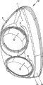
Fig. 1 shows the radiating surface of the housing of headlight arrangement of the present invention,
Fig. 2 A to 2C shows may the arranging of lath 3 of an embodiment of headlight arrangement,
Fig. 3 and Fig. 4 A to 4C show the partial schematic diagram of the another kind of design plan of the headlight arrangement that has a lath 3,
Fig. 5 shows total view of headlight arrangement of the present invention.
The specific embodiment
According to the present invention, design the position of light source top and/or below especially.In the present embodiment, described the special character of main light source lower portion, the light source top corresponding design in position also is fine certainly.The ejaculation direction of light before following direction explanation refers to relatively.It overlaps with travel direction.
Light source and accommodate this light source fluorescent tube 12 below be a radiating surface 1 that is used for the light of a secondary light source.Radiating surface 1 is designed to fiber optic tube at least in part for this reason.Radiating surface 1 has the space 8 that is used for main light source fluorescent tube 12.The surface towards the housing main light source of appreciiable radiating surface 1 is a channel shaped or corrugated in Fig. 1.Realize that by this surface the light of secondary light source outputs to the housing inner chamber, just the residing space of main light source.The lower surface chromium plating of invisible radiating surface 1 in Fig. 1, thus make light can not pass through this surface leakage.The upper surface of radiating surface 1 can partial coating in addition.Partial coating for example can be chromium plating.Pattern arbitrarily can be produced thus, the housing inner chamber can be illuminated also from the outside as seen by this pattern.According to embodiment illustrated in fig. 1, therefore the yet chromium plating of the front end face of radiating surface 1 do not have light to penetrate forward basically.Radiating surface 1 is a transparent moulding.Can adopt acrylics glass as material especially.
For with the light pack of secondary light source in the fiber optic tube of radiating surface 1, a variety of possibilities are arranged, describe in detail below.In all modification, the light of pack in the radiating surface 1 substantially perpendicularly, just upwards or output to downwards in the housing inner chamber along the direction of fluorescent tube 12.Light output illustrates with arrow C in Fig. 1.The fluorescent tube 12 of main light source penetrates downwards thus, highlights especially when connecting secondary light source.
The various possibilities of light pack in the radiating surface 1 are described below.These possibilities realize in the different designs scheme of headlight arrangement 10 or independently or in combination.
In Fig. 1, show two kinds of possibilities of light pack with arrow A and B.Arrow A is represented the light pack by the incline face of radiating surface 1.Arrow B is represented the light pack by the fragment of the back faceted pebble of radiating surface 1.Can arrange directly that on light pack face secondary light source or other light with secondary light source are delivered to the fiber optic tube of radiating surface.
According to another kind of design plan, can use a lath 3 for the light pack, it comprises a bar-shaped fiber optic tube, this fiber optic tube extends along described lath 3.Lath 3 is arranged in the front portion of radiating surface 1.Radiating surface 1 is especially forward by lath 3 sealings.The light of the secondary light source of pack in the bar-shaped fiber optic tube one with radiating surface 1 be delivered to this radiating surface at the interface.Being delivered among Fig. 2 A and the 2B of light illustrates with arrow D.Here, the light pack can one-sidedly carry out also can carrying out by bilateral in the fiber optic tube of lath 3.The side that lath 3 deviates from radiating surface 1 can be provided with a coating 9 on the one hand, thereby does not have light to pass through this face output.This side particularly can chromium plating.Also can carry out light output on the other hand, thereby except sending the light by radiating surface 1, lath 3 can also show as a bright band by this surface.The design of lath 3 can make light also send to the front lower place in addition.Luminously can illuminate anti-dazzle device by this.
The frame mode of different several security strips 3 has been shown in Fig. 2 A to 2C and among the 4A to 4C.Lath 3 for example can setting-in, injection, insertion, engaging or bonding.In addition, as shown in Figure 1, it can be designed to one with radiating surface 1.
In the present embodiment, an integrally formed closed glass plate 2 that extends substantially vertically on radiating surface 1.This face 2 is stretched or is stretched to the direction that does not have the main light source position of housing 11 from housing.It can be used as for example closed glass plate of travel direction indicator lamp of another light source.The light of secondary light source also can pack in this face, shown in arrow E among Fig. 2 A and the 2B.Arrow F among Fig. 2 B then represents the light output of travel direction indicator lamp.
According to present embodiment, secondary light source is the parking light light source.Therefore in this headlight arrangement 10, the parking light function realizes indirectly by illuminating the housing inner chamber.This illuminating can be by realizing in radiating surface 1 lip-deep large tracts of land radiation.Make headlight arrangement produce outward appearance at a kind of very unique, impressive night thus, thereby also make the automobile that has this headlight arrangement be easy to recognize once more.
Claims (14)
1. automobile headlamp device (10) has a housing (11) and at least one by the main light source that this housing (11) accommodates, it is characterized in that,
-housing (11) comprises the radiating surface (1) of a basic horizontal, and this radiating surface is designed to fiber optic tube at least in part,
The light of-one secondary light source can pack arrive in this radiating surface (1),
-light substantially vertically outputs to the housing inner chamber from radiating surface (1).
2. headlight arrangement according to claim 1 (10) is characterized in that, radiating surface (1) is made of the housing bottom side, and light outputs to the housing inner chamber substantially vertically upward from the bottom side.
3. headlight arrangement according to claim 1 (10) is characterized in that, radiating surface (1) is made of the housing upside, and light outputs to the housing inner chamber substantially vertically downward from upside.
4. headlight arrangement according to claim 1 (10), radiating surface (1) essentially horizontally are contained in the main light source below.
5. according to described headlight arrangement (10) one of among the claim 1-4, it is characterized in that the surface that deviates from main light source of radiating surface (1) is light tight at least in part and/or reflective.
6. according to described headlight arrangement (10) one of among the claim 1-4, it is characterized in that the back faceted pebble of radiating surface (1) and/or incline mask have several fragments to be used for the light of pack secondary light source.
7. according to described headlight arrangement (10) one of among the claim 1-4, it is characterized in that, relatively the headlight light emission direction is forward by a lath (3) sealing for radiating surface (1), and this lath comprises a bar-shaped fiber optic tube, the light of secondary light source can pack in this fiber optic tube.
8. headlight arrangement according to claim 7 (10) is characterized in that, pack is delivered to the light in the bar-shaped fiber optic tube on the fiber optic tube of radiating surface (1) so that output does not have light output substantially in the lath in front (3).
9. headlight arrangement according to claim 7 (10) is characterized in that, pack can be exported forward along the headlight radiation direction to the light in the bar-shaped fiber optic tube.
10. headlight arrangement according to claim 7 (10) is characterized in that, lath (3) and radiating surface (1) are designed to one.
11. headlight arrangement according to claim 7 (10) is characterized in that, lath (3) is fixed on the front portion of radiating surface (1).
12., it is characterized in that the surface towards main light source of radiating surface (1) is corrugated and/or channel shaped according to described headlight arrangement (10) one of among the claim 1-4.
13. according to described headlight arrangement (10) one of among the claim 1-4, it is characterized in that radiating surface (1) is blue, fiber optic tube is as blue filter.
14., it is characterized in that secondary light source is a parking light according to described headlight arrangement (10) one of among the claim 1-4.
Applications Claiming Priority (2)
| Application Number | Priority Date | Filing Date | Title |
|---|---|---|---|
| DE10209590A DE10209590A1 (en) | 2002-03-05 | 2002-03-05 | Headlamp assembly for vehicles |
| DE10209590.6 | 2002-03-05 |
Publications (2)
| Publication Number | Publication Date |
|---|---|
| CN1442329A CN1442329A (en) | 2003-09-17 |
| CN100537301C true CN100537301C (en) | 2009-09-09 |
Family
ID=27740637
Family Applications (1)
| Application Number | Title | Priority Date | Filing Date |
|---|---|---|---|
| CNB031070752A Expired - Fee Related CN100537301C (en) | 2002-03-05 | 2003-03-05 | Vehicle head lamp |
Country Status (5)
| Country | Link |
|---|---|
| EP (1) | EP1342616B1 (en) |
| CN (1) | CN100537301C (en) |
| AT (1) | ATE366203T1 (en) |
| DE (2) | DE10209590A1 (en) |
| ES (1) | ES2286342T3 (en) |
Families Citing this family (3)
| Publication number | Priority date | Publication date | Assignee | Title |
|---|---|---|---|---|
| JP4698549B2 (en) * | 2006-10-13 | 2011-06-08 | スタンレー電気株式会社 | Vehicle lighting |
| DE102007048762A1 (en) * | 2007-10-10 | 2009-04-16 | Hella Kgaa Hueck & Co. | Lighting device for vehicles |
| DE102018113768A1 (en) | 2018-06-08 | 2019-12-12 | Automotive Lighting Reutlingen Gmbh | Motor vehicle headlight with at least two light modules |
Family Cites Families (5)
| Publication number | Priority date | Publication date | Assignee | Title |
|---|---|---|---|---|
| DE19652159B4 (en) * | 1996-12-14 | 2006-05-18 | Automotive Lighting Reutlingen Gmbh | Lighting device for vehicles |
| DE19739173A1 (en) * | 1997-09-06 | 1999-03-11 | Hella Kg Hueck & Co | Signal light for vehicles |
| DE19838224C2 (en) * | 1998-08-22 | 2000-11-09 | Daimler Chrysler Ag | Front light assembly for motor vehicles |
| DE19963336A1 (en) * | 1999-12-27 | 2001-07-12 | Hella Kg Hueck & Co | Lighting device and method for illuminating a coupling-out space for vehicles |
| DE10065020B4 (en) * | 2000-09-04 | 2009-02-12 | Automotive Lighting Reutlingen Gmbh | vehicle headlights |
-
2002
- 2002-03-05 DE DE10209590A patent/DE10209590A1/en not_active Withdrawn
-
2003
- 2003-03-03 AT AT03004392T patent/ATE366203T1/en not_active IP Right Cessation
- 2003-03-03 EP EP03004392A patent/EP1342616B1/en not_active Expired - Lifetime
- 2003-03-03 DE DE50307592T patent/DE50307592D1/en not_active Expired - Lifetime
- 2003-03-03 ES ES03004392T patent/ES2286342T3/en not_active Expired - Lifetime
- 2003-03-05 CN CNB031070752A patent/CN100537301C/en not_active Expired - Fee Related
Also Published As
| Publication number | Publication date |
|---|---|
| EP1342616A3 (en) | 2006-04-26 |
| EP1342616B1 (en) | 2007-07-04 |
| ATE366203T1 (en) | 2007-07-15 |
| EP1342616A2 (en) | 2003-09-10 |
| DE50307592D1 (en) | 2007-08-16 |
| ES2286342T3 (en) | 2007-12-01 |
| DE10209590A1 (en) | 2003-10-16 |
| CN1442329A (en) | 2003-09-17 |
Similar Documents
| Publication | Publication Date | Title |
|---|---|---|
| CN101666454B (en) | Lighting device for vehicle | |
| US4949226A (en) | Projector-type lighting device of expanded outline appearance for use as a vehicular headlamp or the like | |
| ES2793964T3 (en) | Car rear light | |
| US6543923B2 (en) | Vehicle lamp | |
| US10036522B2 (en) | Vehicular lamp | |
| JP4664662B2 (en) | Signal or lighting equipment for automobiles | |
| CN106996535A (en) | For illumination of the motor vehicles including opalescence shade or signal optical unit | |
| US7055998B2 (en) | Vehicle lamp having overlapping reflective area | |
| US20070236930A1 (en) | Vehicle lighting device | |
| CN109844403A (en) | Lamp group part for vehicle | |
| US20140140083A1 (en) | Lighting device for a motor vehicle | |
| CN203131654U (en) | Light-guide type daytime running lamp | |
| CN100537301C (en) | Vehicle head lamp | |
| EP2669721A1 (en) | Lighting device for vehicles | |
| US20230204184A1 (en) | Method of manufacturing a blinker module as well as a blinker module, rearview device and motor vehicle | |
| US20150055362A1 (en) | Vehicle rear lamp structure | |
| JP2000133011A (en) | Luminaire for automobile | |
| US6290371B1 (en) | Light for a vehicle | |
| CN107304999B (en) | Vehicular illumination device | |
| CN100537300C (en) | Motor vehical head lamp device having one main light source and one driving direction lamp | |
| US11498480B2 (en) | Illuminating device for vehicle ceiling lamp | |
| JPH09190715A (en) | Unit of head lamp and electric lamp for use in vehicle | |
| CN209893292U (en) | LED vehicle strip work lamp | |
| CN210771935U (en) | Multiplexing formula marker light assembly | |
| CN114072614B (en) | Luminous signal device for vehicle |
Legal Events
| Date | Code | Title | Description |
|---|---|---|---|
| C06 | Publication | ||
| PB01 | Publication | ||
| C10 | Entry into substantive examination | ||
| SE01 | Entry into force of request for substantive examination | ||
| C14 | Grant of patent or utility model | ||
| GR01 | Patent grant | ||
| C17 | Cessation of patent right | ||
| CF01 | Termination of patent right due to non-payment of annual fee |
Granted publication date: 20090909 Termination date: 20100305 |