CN100536503C - Cordless telephone set and additional device of the same - Google Patents
Cordless telephone set and additional device of the same Download PDFInfo
- Publication number
- CN100536503C CN100536503C CNB2006100029683A CN200610002968A CN100536503C CN 100536503 C CN100536503 C CN 100536503C CN B2006100029683 A CNB2006100029683 A CN B2006100029683A CN 200610002968 A CN200610002968 A CN 200610002968A CN 100536503 C CN100536503 C CN 100536503C
- Authority
- CN
- China
- Prior art keywords
- signal
- communication
- unit
- main frame
- signal strength
- Prior art date
- Legal status (The legal status is an assumption and is not a legal conclusion. Google has not performed a legal analysis and makes no representation as to the accuracy of the status listed.)
- Expired - Fee Related
Links
Images


Classifications
-
- H—ELECTRICITY
- H04—ELECTRIC COMMUNICATION TECHNIQUE
- H04M—TELEPHONIC COMMUNICATION
- H04M1/00—Substation equipment, e.g. for use by subscribers
- H04M1/72—Mobile telephones; Cordless telephones, i.e. devices for establishing wireless links to base stations without route selection
- H04M1/725—Cordless telephones
- H04M1/72502—Cordless telephones with one base station connected to a single line
- H04M1/72516—Cordless telephones with one base station connected to a single line with means for out-of-range alerting
-
- H—ELECTRICITY
- H04—ELECTRIC COMMUNICATION TECHNIQUE
- H04B—TRANSMISSION
- H04B17/00—Monitoring; Testing
- H04B17/30—Monitoring; Testing of propagation channels
- H04B17/309—Measuring or estimating channel quality parameters
- H04B17/318—Received signal strength
-
- H—ELECTRICITY
- H04—ELECTRIC COMMUNICATION TECHNIQUE
- H04M—TELEPHONIC COMMUNICATION
- H04M1/00—Substation equipment, e.g. for use by subscribers
- H04M1/72—Mobile telephones; Cordless telephones, i.e. devices for establishing wireless links to base stations without route selection
- H04M1/724—User interfaces specially adapted for cordless or mobile telephones
-
- H—ELECTRICITY
- H04—ELECTRIC COMMUNICATION TECHNIQUE
- H04M—TELEPHONIC COMMUNICATION
- H04M1/00—Substation equipment, e.g. for use by subscribers
- H04M1/72—Mobile telephones; Cordless telephones, i.e. devices for establishing wireless links to base stations without route selection
- H04M1/725—Cordless telephones
- H04M1/72502—Cordless telephones with one base station connected to a single line
Landscapes
- Engineering & Computer Science (AREA)
- Computer Networks & Wireless Communication (AREA)
- Signal Processing (AREA)
- Quality & Reliability (AREA)
- Physics & Mathematics (AREA)
- Electromagnetism (AREA)
- Human Computer Interaction (AREA)
- Mobile Radio Communication Systems (AREA)
- Telephone Function (AREA)
Abstract
本发明公开了一种用于无绳电话装置的附加装置,其包括:与主机进行无线电通信的通信单元;决定用于进行可将信号发送到主机或从主机接收信号的通信的无线电信道的通信控制单元;显示信息的显示单元;周期性地检测由通信单元从主机接收的无线电信号的信号强度的信号强度检测单元;基于以前获得的多个信号强度,估计来自主机的无线电信号的当前信号强度的信号强度估计单元;和基于由信号强度估计单元估计的信号强度,在显示单元上显示与主机的通信状态的显示控制单元。

The present invention discloses an add-on device for a cordless telephone device, comprising: a communication unit for performing radio communication with a main unit; a communication control for determining a radio channel for communication that can transmit signals to or receive signals from the main unit unit; a display unit for displaying information; a signal strength detection unit for periodically detecting the signal strength of a radio signal received by the communication unit from the host; and for estimating a current signal strength of a radio signal from the host based on a plurality of signal strengths previously obtained a signal strength estimating unit; and a display control unit for displaying a state of communication with the host on the display unit based on the signal strength estimated by the signal strength estimating unit.
Description
技术领域 technical field
本发明的各实施方式涉及包括与电话线路网络连接的主机和通过无线电路与主机连接的移动装置的无绳电话装置和用于该电话装置的移动装置。Embodiments of the present invention relate to a cordless telephone device including a main unit connected to a telephone line network and a mobile unit connected to the main unit via a wireless circuit, and a mobile unit for the telephone unit.
背景技术 Background technique
传统上,包括与电话线路网络连接的主机和通过无线电路与主机连接的移动装置的无绳电话装置是众所周知的。Conventionally, a cordless telephone set comprising a main unit connected to a telephone line network and a mobile unit connected to the main unit through a wireless circuit is well known.
这种无绳电话装置是众所周知的,其中当用户使用移动装置(即移动装置通过主机与电话线路网络连接)通话时,移动装置测量从主机发送的无线电信号的信号强度,并将测量的结果显示在移动装置的显示器上(例如参考JP-B-3-32254)。Such cordless telephone devices are well known in which when a user talks with a mobile device (i.e. the mobile device is connected to the telephone line network through the host device), the mobile device measures the signal strength of the radio signal sent from the host device and displays the result of the measurement on On the display of the mobile device (for example, refer to JP-B-3-32254).
用这种电话装置,用户在电话通话过程中通过观看显示器可以得知主机和移动装置之间的通信状态。With this telephone device, the user can know the communication status between the host and the mobile device by watching the display during the telephone conversation.
发明内容 Contents of the invention
顺便提及,在移动装置中测量的信号强度取决于用户持有移动装置的位置而变化。Incidentally, the signal strength measured in the mobile device varies depending on where the user holds the mobile device.
因此,当用户在电话通话期间将移动装置从耳朵移到手上以确认显示器上的信号强度时,在显示器上显示的信号强度改变,以致用户不能得知在电话通话期间在主机和移动装置之间的通信状态。Therefore, when the user moves the mobile device from the ear to the hand to confirm the signal strength on the display during a phone call, the signal strength displayed on the display changes so that the user cannot know that there is a problem between the host and the mobile device during the phone call. communication status.
本发明提供一种在其中用户能够得知接近于通话状态的通信状态的无绳电话装置及其附加装置。The present invention provides a cordless telephone device and an additional device thereof in which a user can know a communication state close to a talking state.
根据本发明的一实施方式,提供一种用于无绳电话装置的附加装置,其包括:采用用于无线电通信的预定无线电信道与主机进行无线电通信的通信单元;当通过外部操作输入呼叫命令或通过无线电从主机发送的呼叫信号被通信单元接收时,决定可以用来将通话信号发送到主机或从主机接收通话信号的用于进行通信的无线电信道,并且随后采用所决定的用于通信的无线电信道,通过使通信单元能够与主机进行无线电通信来发送或接收通话信号的通信控制单元;显示信息的显示单元;当在通信控制单元的控制下,通信单元借助用于通信的无线电信道与主机进行无线电通信时,周期性地检测由通信单元从主机接收的无线电信号的信号强度的信号强度检测单元;基于多个以前获得的信号强度,通过随后获得由信号强度检测单元检测的信号强度,来估计来自主机的无线电信号的当前信号强度的信号强度估计单元;和基于由信号强度估计单元估计的信号强度,在显示单元上显示与主机的通信状态的显示控制单元。According to an embodiment of the present invention, there is provided an add-on device for a cordless telephone device, which includes: a communication unit for radio communication with a host using a predetermined radio channel for radio communication; when a call command is input by an external operation or by When a call signal sent by radio from the host is received by the communication unit, a radio channel for communication that can be used to transmit a call signal to or receive a call signal from the host is determined, and then the decided radio channel for communication is used , a communication control unit that transmits or receives a call signal by enabling the communication unit to perform radio communication with the host; a display unit that displays information; when under the control of the communication control unit, the communication unit performs radio communication with the host by means of a radio channel for communication During communication, a signal strength detection unit that periodically detects the signal strength of a radio signal received by the communication unit from the host computer; based on a plurality of previously obtained signal strengths, by subsequently obtaining the signal strength detected by the signal strength detection unit, it is estimated from a signal strength estimating unit of a current signal strength of a radio signal of the host; and a display control unit for displaying a communication state with the host on a display unit based on the signal strength estimated by the signal strength estimating unit.
使用用于无绳电话装置的附加装置,当在通信控制单元的控制下,通信单元借助用于通信的无线电信道与主机进行无线电通信时,信号强度检测单元周期性地检测被通信单元从主机接收的无线电信号的信号强度,并且信号强度估计单元基于先前通过按序获取由信号强度检测单元检测到的信号强度而获取到的多个信号强度,估计来自主机的无线电信号的当前信号强度。基于由信号强度估计单元估计的信号强度,显示控制单元在显示单元上显示与主机的通信状态。Using an add-on for a cordless telephone set, when the communication unit performs radio communication with the host by means of a radio channel for communication under the control of the communication control unit, the signal strength detection unit periodically detects the signal received by the communication unit from the host The signal strength of the radio signal, and the signal strength estimating unit estimates a current signal strength of the radio signal from the host based on a plurality of signal strengths previously acquired by sequentially acquiring signal strengths detected by the signal strength detection unit. The display control unit displays a communication state with the host on the display unit based on the signal strength estimated by the signal strength estimation unit.
用这种用于无绳电话装置的附加装置,当在通信控制单元的控制下,通信单元借助用于通信的无线电信道与主机进行无线电通信时(即,当用户正在使用附加装置通话时),甚至当用户将附加装置从耳朵移开以确认在显示单元上显示的通信状态时,通信状态也不会快速改变。由此,用户可以知道与通话条件的通信状态相似的通信状态。With this attachment for a cordless telephone set, when the communication unit performs radio communication with the host by means of a radio channel for communication under the control of the communication control unit (that is, when the user is talking using the attachment), even When the user removes the additional device from the ear to confirm the communication status displayed on the display unit, the communication status does not change rapidly. Thereby, the user can know the communication state similar to that of the call condition.
附图说明 Description of drawings
参考附图将更易于描述本发明的说明性实施方式。Illustrative embodiments of the present invention will be more readily described with reference to the accompanying drawings.
图1是根据本发明的一实施方式的无绳电话装置的透视图;1 is a perspective view of a cordless telephone device according to an embodiment of the present invention;
图2是用于无绳电话装置的移动装置和充电台的透视图;Figure 2 is a perspective view of a mobile unit and charging station for a cordless telephone unit;
图3是显示无绳电话装置的电气配置的方框图;Fig. 3 is a block diagram showing the electrical configuration of the cordless telephone device;
图4是用于解释图形生成表的说明图;FIG. 4 is an explanatory diagram for explaining a graph generation table;
图5是显示根据第一实施方式当用户从移动装置拨打电话时,在主机和移动装置之间执行的操作的顺序图;5 is a sequence diagram showing operations performed between the host and the mobile device when the user makes a call from the mobile device according to the first embodiment;
图6是显示根据第一实施方式当无绳电话装置从外部呼入电话时,在主机和移动装置之间执行的操作的顺序图;6 is a sequence diagram showing operations performed between the host and the mobile device when the cordless telephone device calls in from the outside according to the first embodiment;
图7是显示根据第一实施方式当有来电或在移动装置进行通话开始操作时,由控制部分执行的处理的流程图;7 is a flow chart showing processing performed by the control section when there is an incoming call or a call start operation is performed at the mobile device according to the first embodiment;
图8是用于解释当用户在移动装置上通话时,在显示板上显示的图形的说明图;8 is an explanatory diagram for explaining graphics displayed on a display panel when a user talks on a mobile device;
图9是用于解释在改变后图形的生成表的说明图;FIG. 9 is an explanatory diagram for explaining a generation table of graphics after change;
图10是显示根据第二实施方式的当有来电或在移动装置所做出通话开始操作时,由控制部分执行的处理的流程图;10 is a flowchart showing processing performed by the control section when there is an incoming call or a call start operation is made at the mobile device according to the second embodiment;
图11是显示根据第二实施方式的在主机的无线电通信控制部分中执行的主机RSSI值传送处理的流程图;11 is a flowchart showing host RSSI value transmission processing executed in the radio communication control section of the host according to the second embodiment;
图12是显示根据第二实施方式当用户从移动装置拨打电话时,在主机和移动装置之间执行的操作的顺序图。12 is a sequence diagram showing operations performed between a host and a mobile device when a user makes a call from the mobile device according to the second embodiment.
具体实施方式 Detailed ways
下面将参考附图描述本发明的各实施方式。Embodiments of the present invention will be described below with reference to the accompanying drawings.
[第一实施方式][first embodiment]
图1是根据本发明的一实施方式的无绳电话装置的透视图。图2A是显示移动装置50的背面的透视图,图2B是充电台80的透视图。图3是显示无绳电话装置1的电气配置的方框图。FIG. 1 is a perspective view of a cordless telephone device according to an embodiment of the present invention. FIG. 2A is a perspective view showing the back of the
无绳电话装置1具有借助电话线路网络100(见图3)通过电话通话的功能(通话功能)和借助电话线路网络100发送或接收图像数据的功能(传真功能),并且如图1所示,包括与电话线路网络100连接的主机10,借助无线电电路与主机连接的移动装置50,以及连接到未显示的外部电源的用于在预定电压下使移动装置50充电的充电台80,移动装置50可分开放置。在该实施方式的无绳电话装置1中,关于传真功能的元件与本发明不直接相关,在此不做描述。The
主机10具有作为主机外壳11的侧部上的发送接收器的电话听筒12,其中当使用时,将电话听筒与主机10的主体分离。而且,显示板13用于显示与各种功能和各种操作按钮14相关的信息,操作按钮14包括用于输入对方电话号码的拨号按钮14a和被操作用来从在显示板13上显示的菜单屏幕中选择的选择按钮14b,显示板13被设置在主机外壳11的上表面上。显示板13是具有用于从背面照亮显示屏的背光的液晶显示器(LCD)。The
移动装置50包括用于显示与各种功能相关的信息的显示板53,包括用于输入对方电话号码的拨号按钮54a、在开始外线呼叫时操作的外线呼叫按钮54b、在终止通话时操作的断开按钮54c和用于从显示在显示板53上的菜单屏幕中选择操作的选择按钮54d的各种操作按钮54,和为了在具有电话听筒形状的移动装置主体外壳51的表面上从充电台80给整个移动装置50提供电力,以给电池74(见图3)充电的充电端子55(见图2A)。The
显示板53是具有用于从背面照亮显示屏的背光的液晶显示器(LCD)。The
充电台80包括用移动装置50可分开地放置在其上的放置凹部81a形成的充电台主体81,和安装在设置凹部81a内的充电端子82,其用于当移动装置50被放置在设置凹部81a上时与充电端子55接触,如图2B所示。The charging
参考图3,下面将描述无绳电话装置1的电气配置。Referring to Fig. 3, the electrical configuration of the
主机10包括用于控制主机10的整个操作的控制部分20、电话听筒12、显示板13、操作按钮14和用于将语音信号(对应于通话信号)或数据信号用无线电发送或到移动装置50或从移动装置50接收的无线电通信部分30。The
来自操作按钮14的输出信号、来自无线电通信部分30的输出信号(语音或数据信号)和来自无绳电话装置1的外部的语音信号被输入控制部分20。An output signal from the
并且,控制部分20在从无绳电话装置1外部输入或输出的语音信号的传送目的地和传送源之间建立传送路径。更具体地,当电话听筒12从主机10的主体移开时,传送路径被切换到电话听筒12,或当通过移动装置50进行用于开始通话的通话开始操作时,传送路径被切换到无线电通信部分30。Also, the
而且,控制部分20将用于与移动装置50进行无线电通信的数据信号或语音信号输出到无线电通信部分30,并将来自电话听筒12和无线电通信部分30的语音信号输出到无绳电话装置1的外部。Also, the
无线电通信部分30包括由CPU、RAM、ROM和A/D转换器组成的无线电通信控制部分32、EEPROM 34、压缩扩展器36和用于与移动装置50进行无线电通信的RF模块38。The radio communication section 30 includes a radio
压缩扩展器36通过RF模块38获得从移动装置50发送的无线电信号,并将其信号分离成语音信号和数据信号,语音信号被送到控制部分20,数据信号被送到无线电通信控制部分32。并且,压缩扩展器36将来自控制部分20的语音信号或来自无线电通信控制部分32的数据信号发送到RF模块38。The
RF模块38被配置成可与无线电通信控制部分32进行通信,根据来自无线电通信控制部分32的命令,从多个具有不同频率的无线电信道中选择在无线电通信中使用的无线电信道,并将来自压缩扩展器36的输出信号发送到移动装置50,以及使用选择的无线电信道,接收从移动装置50发送的无线电信号。The
在这个实施方式,RF模块38用于无线电通信的无线电信道是在380MHz波段中每个无线电信道之间的频率间隔为12.5kHz的89个无线电信道。移动装置50(更具体是RF模块68)使用的用于无线电通信的无线电信道是在280MHz波段中每个无线电信道之间的频率间隔为12.5kHz的89个无线电信道。它们当中,46信道和89信道只用来发送或接收数据信号,剩下的1信道至45信道和47信道至88信道的任何一个用来发送或接收语音信号。在下面的说明中,46信道和89信道被称为控制信道,1至45和47至88信道被称为通信信道以区别在主机10和移动装置50之间使用的无线电信道。In this embodiment, the radio channels used by the
并且,RF模块38检测由无线电从外面接收的信号的信号强度,并将其检测结果输出到无线电通信控制部分32的A/D转换器。在这个实施方式,无线电控制部分32的A/D转换器将从RF模块38输入的检测结果转换成8位的数字值。Also, the
从控制部分20或压缩扩展器36输出的数据信号被输入无线电通信控制部分32。无线电通信控制部分32将来自控制部分20的数据信号输出到压缩扩展器36。The data signal output from the
并且,当主机10开始与移动装置50通信时,无线电控制部分32基于由RF模块38检测的信号强度,选择可用的无线电信道,并且将其结果发送到RF模块。And, when the
由此,主机10使用由无线电通信控制部分32选择的无线电信道,开始与移动装置50的无线电通信。Thus, the
移动装置50包括用于控制移动装置50整个操作的控制部分60、显示板53、操作按钮54、接收器62、话筒64、压缩扩展器66,用于在与主机10(更具体是RF模块38)的无线电通信中发送或接收语音信号或数据信号的RF模块68、EEPROM 70、用于从后面照亮操作按钮54的操作按钮LED 72、用于给整个移动装置50提供电力的电池74,用于电连接到充电端子82的充电端子55,和用于借助充电端子55在充电台80提供的电源电压下给电池74充电的充电电路76。The
压缩扩展器66通过RF模块68获得从主机10发送的无线电信号,并将其信号分割成语音信号和数据信号,语音信号被送到接收器62,数据信号被发送到控制部分60。并且,压缩扩展器66将来自麦克风64的语音信号或来自控制部分60的数据信号发送到RF模块68。The
RF模块68被配置成可与控制部分60进行通信,根据来自控制部分60的命令从89个无线电信道中选择在无线电通信中使用的无线电信道,并将来自压缩扩展器66的输出信号发送到主机10,以及使用选择大的无线电信道接收从主机10发送的无线电信号。The
并且,RF模块68检测由无线电从外面接收的信号的信号强度,并将其检测结果输出到包含在控制部分60中的A/D转换器。在这个实施方式,控制部分60的A/D转换器将从RF模块68输入的检测结果转换成8位的数字值(下文中称为RSSI值)。Also, the
控制部分60包括CPU、RAM、ROM和A/D转换器。来自操作按钮54的输出信号或来自压缩扩展器66的数据信号被输入到控制部分60中。The
并且,控制部分60将用于与主机10无线电通信的数据信号输出到压缩扩展器66。Also, the
此外,控制部分60被配置成与RF模块68可进行通信,并且当移动装置50开始与主机10通信时,基于由RF模块68检测的信号强度选择可用的无线电信道,以及将其结果发送到RF模块68。In addition, the
由此,移动装置50使用由控制部分60选择的无线电信道开始与主机10的无线电通信。Thus, the
此外,当移动装置50通过通信信道与主机10进行无线电通信时,控制部分60使RF模块68借助通信信道周期性地获得从主机10发送的无线电信号的信号强度,并计算在过去获得的五个信号强度(即RSSI值)的平均值。Furthermore, when the
控制部分60将计算的平均值与多个存储在ROM中的阈值进行比较,将平均值阶段性地数字化,基于数字化的结果产生典型图形,并将产生的图形作为与主机10的通信状态显示在显示板53上。The
更具体地,将图形生成表存储在控制部分60的ROM中。More specifically, the graphic generation table is stored in the ROM of the
在图形生成表中,根据多个阈值,将0至255个值分成5个阶段,并将由控制部分60产生的图形与每个阶段相关联,如图4所示。In the graph generation table, 0 to 255 values are divided into 5 stages according to a plurality of thresholds, and a graph generated by the
就是说,图形生成表显示对应于如阈值一样较好的通信状态的图形较高(在图4中向下),这样最低水平(0至99)对应于指示移动装置50与主机10不能通信的状态的图形,第二最低水平(100至129)对应于指示主机10的通信状态最差的状态的图形,等等。在这个实施方式,通信状态最差的状态是主机10与移动装置50可通信的状态,但是通信状态最差。That is, the graph generation table shows that graphs corresponding to better communication states as thresholds are higher (downward in FIG. state, the second lowest level (100 to 129) corresponds to a state graph indicating the worst communication state of the
控制部分60计算过去从RF模块68获得的5个RSSI值的平均值,并通过参考图形生成表提取与计算的平均值对应的图形。控制部分60从图形生成表提取图形并将图形显示在显示板53上。The
接着,充电台80具有从必需的外部电源供给电力以产生预定的电源电压的充电端子82,并向移动装置50提供电力。Next, the charging
参考图5,下面将描述当用户从移动装置50打电话时在主机10和移动装置50之间进行的操作。Referring to FIG. 5, operations performed between the
当用户在非通话状态(待机状态)按下移动装置50的外线呼叫按钮54b以进行通话开始操作时,使用预定的控制信道(例如46信道),移动装置50将呼叫命令发送给主机10。When the user presses the external
收到呼叫命令的主机10选择一个用于与移动装置50通信的通信信道(例如5信道),并使用控制信道(46信道),将代表选择的通信信道的指定通信信道命令发送给移动装置50。The
收到指定的通信信道命令的移动装置50在RF模块68获得在5信道的频带中的无线电信号的信号强度,并基于获得的信号强度,确定5信道是否可用。在图5中,为了解释,假定5信道被确定可用。The
作为确定的结果,因为5信道是可用的通信信道,移动装置50使用46信道,将指示5信道是可用信道的指定通信信道OK应答发送到主机10。As a result of the determination, since the 5 channel is an available communication channel, the
收到指定通信信道OK应答的主机10使用46信道,将指示从那时在5信道进行无线电通信的通信信道决定通知发送到移动装置50。The
收到通信信道决定通知的移动装置50能够用于通话。本文所用的可通信意指在移动装置50借助主机10连接到电话线路网络100的状态下,在主机10和移动装置50之间的通信建立在指定的通信信道上。The
其后,用户在移动装置50上进行拨号操作,主机10将拨号信号发送到电话线路网络100以应答对方的电话装置,由此能够与对方的电话装置进行外线通话。Afterwards, the user performs a dial operation on the
在此,变成通话使能状态的移动装置50周期性地(在该实施方式每0.5秒)获得通过通信信道(在该实施例中5信道)从主机10发送的无线电信号的信号强度,并基于在过去获得的5个信号强度的平均值,将从图形生成表提取的图形作为与主机10的通信状态显示在显示板53上。Here, the
其后,当移动装置50的用户按下移动装置50的断开按钮54c以进行通话终止操作时,移动装置50将通话终止命令发送给主机10,并停止图形的显示。Thereafter, when the user of the
收到通话终止命令的主机10终止与对方电话装置的外线通话。The
参考图6,下面将描述当在无绳电话装置1上有从对方电话装置呼入的呼叫时在主机10和移动装置50之间进行的操作。Referring to FIG. 6, the operations performed between the
首先,当在主机10上检测到从对方电话装置呼入的呼叫时,主机10选择一个用于与移动装置50无线电通信的通信信道(例如5信道),并使用预定的控制信道(例如46信道)将指示选择的通信信道的指定的通信信道命令发送到移动装置50。First, when an incoming call from the other party's telephone device is detected on the
收到指定的通信信道命令的移动装置50确定5信道是否可用,并且如果确定5信道可用,如上所述使用46信道,向主机10发送指定的通信信道OK应答。The
收到指定的通信信道OK应答的主机10使用46信道,将指示从那时在5信道进行无线电通信的通信信道决定通知发送到移动装置50。The
当移动装置50收到通信信道决定通知时,移动装置50能够用于通话。When the
更具体地,收到通信信道决定通知的移动装置50通过铃声通知用户来电呼入。在移动装置50的用户按下外线呼叫按钮54b以进行通话开始操作后,能够进行与对方的电话装置的外线通话。More specifically, the
并且,当移动装置50由于从外面呼入的呼叫而变成通话使能状态时,如上所述,移动装置50在显示板53上显示与主机10的通信状态。And, when the
其后,当移动装置50的用户按下移动装置50的断开按钮54c以进行电话呼叫终止操作时,移动装置50向主机10发送电话呼叫终止命令,并停止在显示板53上显示图形。Thereafter, when the user of the
收到通话终止命令的主机10终止与对方电话装置的外线通话。The
参考图7的流程图,下面将描述当有来电或在移动装置50进行通话开始操作时,在控制部分60执行的过程。Referring to the flowchart of FIG. 7, the process performed at the
当控制部分60开始图7的处理时,首先在S110进行用于决定与主机10无线电通信的通信信道的通信信道决定处理。在这个通信信道决定处理中,从图形生成表中提取对应于第二最低水平的图形(指示与主机10的通信状态最差的状态的图形)并将其显示在显示板53上。When the
在S120,其后使用的无线电信道从当前使用的控制信道切换到在S110决定的通信信道。At S120, the radio channel used thereafter is switched from the currently used control channel to the communication channel decided at S110.
在S130,从RF模块68获得当前使用的通信信道的RSSI值,并将获得的RSSI值存储在例如EEPROM 70中。At S130, the RSSI value of the currently used communication channel is obtained from the
在S140,读取存储在EEPROM 70中的RSSI值,并计算读取的RSSI值的平均值。At S140, the RSSI values stored in the
在S150,通过参考存储在ROM中的图形生成表提取与在S140中计算的平均值相对应的图形。At S150, a graph corresponding to the average value calculated at S140 is extracted by referring to a graph generation table stored in the ROM.
在S160,将S150中提取的图形输出到显示板53,并显示在显示板53上。In S160 , the graphics extracted in S150 are output to the
在此,如果在S140计算的平均值是200,如图8所示,对应于图4中最高水平(180至255)的图形显示在显示板53上的左下区域。在显示板53上,除了在S160显示的与主机10的通信状态之外,还显示当前时间和移动装置50的操作状态。Here, if the average value calculated at S140 is 200, as shown in FIG. 8, a graph corresponding to the highest level (180 to 255) in FIG. On the
在S170,清除在过去除RSSI值之外的四个值。At S170, four values other than the RSSI value in the past are cleared.
在S180,确定是否输入通话终止命令。At S180, it is determined whether a call termination command is input.
当在S180确定输入通话终止命令时,步骤转到S190,或者当在S180确定不输入通话终止命令时,步骤转到S130。When it is determined at S180 that a call termination command is input, the step goes to S190, or when it is determined at S180 that a call termination command is not input, the step goes to S130.
在S190,停止图形向显示板53的输出。随后,在S200,清除存储在EEPROM 70中的所有RSSI值,并结束该步骤。In S190, the output of graphics to the
当存储在EEPROM 70中的RSSI值的数小于或等于4,在S140计算仅存储在EEPROM 70中的RSSI值的平均值。When the number of RSSI values stored in the
如上所述,当用户使用移动装置50通话时(移动装置50经由通信信道与主机10进行无线电通信),第一实施方式的移动装置50周期性地检测经由通信信道发送的无线电信号的信号强度,并随后获得检测到的信号强度。然后基于在过去获得的5个信号强度(RSSI值)的平均值,移动装置50产生典型图形,并将图形作为与主机10的通信状态显示在显示板53上。As mentioned above, when the user uses the
用以上无绳电话装置1,当用户使用移动装置50通话时,用户能够得知与通话状态的通信状态相似的通信状态,因为即使用户将移动装置50移开耳朵以确认在显示板53上显示的通信状态,通信状态也不会快速改变。With the above
并且,自从有呼叫命令或呼入来电直到使用通信信道进行与主机10的无线电通信,移动装置50在显示板53上显示与主机10的通信状态最差的指示,由此用户可以判断建立了可通信的状态。And, since there is a call command or an incoming call until radio communication with the
并且,用第一实施方式的无绳电话装置1,由于基于在过去的5个RSSI值的平均值,得到当前的信号强度,所以当前信号强度可以不受干扰的影响简单地得到和导出。Furthermore, with the
并且,用无绳电话装置1,由于在过去的5个RSSI值的平均值与图形生成表中的众多阈值比较,并且与其平均值相对应的图形显示在显示板53上,所以用户仅扫视显示板53以确认与主机10的通信状态。And, with the
在这个实施方式,RF模块68用作通信单元和信号强度检测单元,图7的流程图起到通信控制单元的作用。在图6中,从主机10发送的指定通信信道命令用作呼叫信号,控制信道用作控制无线电信道,通信信道用作通信无线电信道。并且,显示板53用作显示单元,在S130和S140的处理起到信号强度估计单元的作用,在S110、S150和S160的处理起到显示控制单元的作用。In this embodiment, the
[第二实施方式][Second Embodiment]
参考图9至12,下面将描述根据本发明的第二实施方式的无绳电话装置2。在第二实施方式的无绳电话装置2中,与第一实施方式的无绳电话装置1相反,主机10检测来自移动装置50的无线电信号的信号强度,并将其检测结果发送到移动装置50,同时移动装置50基于从主机10接收的检测结果更新图形生成表,并将与主机10的通信状态显示在显示板53上。在图9至12中,图9是用于解释改变后的图形生成表的说明图,图10是显示当在第二实施方式的移动装置50有呼入来电或执行通话开始操作时,在控制部分60执行的处理的流程图。图11是显示在根据第二实施方式的主机10的无线电通信控制部分32中执行的处理的流程图。图12是显示当用户从根据第二实施方式的移动装置50打电话时,在主机10和移动装置50之间执行的操作的顺序图。Referring to Figs. 9 to 12, a
根据第二实施方式的移动装置50与根据第一实施方式的移动装置50有以下两点不同。The
首先,除了图4的图形生成表,如图9所示的改变后的图形生成表存储在控制部分60的ROM中。更具体地,改变后的图形生成表中对于每个水平的阈值被设置成高于与其对应的图形生成表中对于每个水平的阈值,如图9所示。First, in addition to the graphic generation table of FIG. 4 , a changed graphic generation table as shown in FIG. 9 is stored in the ROM of the
控制部分60执行图10的处理,而不是图7的处理。图10的处理像图7的处理一样当有呼入来电或执行通话开始操作时在控制部分60中进行。在图10的处理中,相同的步骤由与图7的处理中相同的步骤编号给出,不作详细描述。The
就是说,控制部分60执行图9的处理,并结束步骤S110和S120,步骤转到S310。That is, the
在S310,将从移动装置50接收无线电信号时由主机10检测的信号强度从主机10发送到移动装置50的命令(下文中称作主机RSSI值发送命令)输出到压缩扩展器66。在下面的解释中,为了区分由主机10和移动装置50获得的信号强度(RSSI值),由主机10获得的信号强度(8位数字值)称为主机RSSI值,由移动装置50获得的RSSI值称为移动装置RSSI值。A command (hereinafter referred to as a host RSSI value transmission command) of signal strength detected by the
当执行步骤S310时,移动装置50经由通信信道从RF模块68发送主机RSSI发送命令。When step S310 is executed, the
随后,在S320,该步骤等待直到从主机10收到主机RSSI值,并且当收到主机RSSI值时,将收到的主机RSSI值存储在例如RAM中。Then, at S320, the step waits until the host RSSI value is received from the
其后,在S330,获得在收到主机RSSI值时的移动装置RSSI值,并存储在EEPROM 70中。Thereafter, at S330, the mobile device RSSI value at the time of receiving the host RSSI value is obtained, and stored in the
在S340,计算在S330中存储在EEPROM 70中的移动装置RSSI值和在S320中存储在RAM中的主机RSSI值之间的差值。At S340, the difference between the mobile device RSSI value stored in the
在S350,确定在S340计算的差是否大于或等于预定的阈值(在第二实施方式为30)。在第二实施方式,用于该确定的阈值被设置为30,但是可以适当地设置成其它值。At S350, it is determined whether the difference calculated at S340 is greater than or equal to a predetermined threshold (30 in the second embodiment). In the second embodiment, the threshold used for this determination is set to 30, but may be set to other values as appropriate.
在S350,当确定该差值大于或等于30时,步骤转到S360,在此要在S370参考的表从图形生成表变成改变后的图形生成表,步骤转到S140。At S350, when it is determined that the difference is greater than or equal to 30, the step goes to S360, where the table to be referenced at S370 is changed from the graph generation table to the changed graph generation table, and the step goes to S140.
另一方面,在S350,当确定该差不大于或等于30,步骤直接转到S140。On the other hand, at S350, when it is determined that the difference is not greater than or equal to 30, the step goes directly to S140.
当步骤S140结束时,在S370,通过参考图形生成表提取与S140计算的平均值相对应的图形。When step S140 ends, at S370, a graph corresponding to the average value calculated at S140 is extracted by referring to the graph generation table.
更具体地,在S370,当这时执行图10处理中的步骤S360时,通过参考改变后的图形生成表提取与在S140计算的平均值相对应的图形,或者相反地,当这时不执行图10处理中的步骤S360时,参考图形生成表提取与S140计算的平均值相对应的图形。More specifically, at S370, when step S360 in the processing of FIG. At step S360 in the process of FIG. 10 , a graph corresponding to the average value calculated at S140 is extracted with reference to the graph generation table.
当步骤S370结束时,步骤从S160转到S170至S180。如果确定在S180不输入通话终止命令,步骤转到S380。When step S370 ends, the steps go from S160 to S170 to S180. If it is determined that the call termination command is not input at S180, the step goes to S380.
在S380,获得移动装置RSSI值,并存储在EEPROM 70中,并且步骤转到S140。At S380, the mobile device RSSI value is obtained and stored in the
并且,在S180,当确定输入通话终止命令时,如第一实施方式,步骤从S190到达S200,并结束。And, in S180, when it is determined that a call termination command is input, as in the first embodiment, the steps go from S190 to S200 and end.
然后,根据第二实施方式的主机10在无线电通信控制部分32执行图11的主机RSSI值发送处理这一点上不同于根据第一实施方式的主机10。Then, the
就是说,当主机10收到来自移动装置50的主机发送命令时,在无线电通信控制部分32进行主机RSSI值发送处理。That is, when the
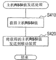
当执行主机RSSI值发送处理时,首先,在S410通过RF模块38获得经由移动装置50使用的通信信道发送的无线电信号的信号强度。When the host RSSI value transmission process is performed, first, the signal strength of the radio signal transmitted via the communication channel used by the
随后,在S420,通过向压缩扩展器36输出获得的信号强度(即主机RSSI值),主机RSSI值由无线电发送到RF模块38,并结束主机RSSI值发送处理。Subsequently, at S420, the host RSSI value is transmitted by radio to the
参考图12,下面将描述当用户从根据第二实施方式的移动装置50打电话时,在主机10和移动装置50之间执行的操作。Referring to FIG. 12 , operations performed between the
在无绳电话装置2中,当通过用户在待机状态按下外线呼叫按钮54b而执行通话开始操作时,根据与图5相同的步骤,通过将控制信道(例如46信道)切换到通信信道(例如5信道),移动装置50变成可通信的状态。In the
在此,当移动装置50变成可通信的状态时,它使用通信信道(5信道),将主机RSSI值发送命令发送到主机10。Here, when the
收到主机RSSI值发送命令的主机10获得在5信道从移动装置50发送的无线电信号的信号强度,并将获得的信号强度(主机RSSI值)通过5信道发送到移动装置50。The
收到主机RSSI值的移动装置50获得在5信道上从主机10发送的无线电信号的信号强度,并将获得的移动装置RSSI值与主机RSSI值比较。The
当移动装置RSSI值和主机RSSI值之间的差大于或等于30时,主机50通过参考改变后的图形生成表显示图形,或者相反,当移动装置RSSI值和主机RSSI值之间的差不大于或等于30时,通过参考图形生成表显示图形。When the difference between the RSSI value of the mobile device and the RSSI value of the host is greater than or equal to 30, the
其后,当移动装置50的用户按下移动装置50的断开按钮54c以执行通话终止操作时,移动装置50将通话终止命令发送到主机10,并停止图形显示。Thereafter, when the user of the
收到通话终止命令的主机10终止与对方电话装置的外线通话。The
另一实施方式,当无绳电话装置2具有来自外面的呼入时,移动装置50根据与图5相同的步骤,通过将控制信道(例如46信道)切换成通信信道(例如5信道)而变成可通信的状态。In another embodiment, when the
下面,采用图12的相同步骤。Next, the same steps as in Fig. 12 are adopted.
用根据如上所述的第二实施方式的无绳电话装置2,移动装置50将包括从移动装置50到主机10的通信状态显示在显示板53上,由此通知用户更正确的通信状态。With the
在第二实施方式,图10的流程图起到通信控制单元的作用,步骤S310至S360起到阈值改变单元的作用,主机RSSI值发送处理起到测量结果传送单元的作用。In the second embodiment, the flowchart of FIG. 10 functions as a communication control unit, steps S310 to S360 function as a threshold changing unit, and the host RSSI value transmission process functions as a measurement result transmitting unit.
尽管上面已经描述本发明的实施方式,但可以做各种修改。Although the embodiments of the present invention have been described above, various modifications can be made.
尽管第一实施方式和第二实施方式的无绳电话装置1和2包括传真功能,只要它有电话装置的功能,它们可以包括任何其它功能以达到以上实施方式的相同效果。Although the
并且,尽管在该实施方式中,在S140计算在过去的5个移动装置RSSI值的平均值,也可以计算在过去多个移动装置RSSI值的平均值或在过去多个移动装置RSSI值的偏差。And, although in this embodiment, the average value of RSSI values of five mobile devices in the past is calculated at S140, the average value of RSSI values of a plurality of mobile devices in the past or the deviation of RSSI values of a plurality of mobile devices in the past may be calculated .
并且在以上实施方式中,在步骤S110在显示板53上显示的图形是表示与主机10的通信状态最差的状态的图形,但可以是表示与主机10的通信状态是最优秀的状态的图形(在图4或图9中的最低图形)。And in the above embodiment, the graph displayed on the
并且,在该实施方式,在S160在显示板53上显示从图形生成表提取的图形,但是在S160可以直接显示在S140计算的平均值。在这种情况下,可以不执行步骤S150。Also, in this embodiment, the graph extracted from the graph generation table is displayed on the
并且,步骤S110可以被配置成执行从S130至S170的处理。And, step S110 may be configured to perform the processing from S130 to S170.
并且,在第二实施方式中,在步骤S120结束后,主机RSSI值发送命令被一次发送,但是它也可以以预定的间隔发送。Also, in the second embodiment, the host RSSI value transmission command is transmitted once after step S120 ends, but it may also be transmitted at predetermined intervals.
Claims (5)
Applications Claiming Priority (2)
| Application Number | Priority Date | Filing Date | Title |
|---|---|---|---|
| JP2005018695 | 2005-01-26 | ||
| JP2005018695A JP3998019B2 (en) | 2005-01-26 | 2005-01-26 | Cordless telephone device and slave unit of the device |
Publications (2)
| Publication Number | Publication Date |
|---|---|
| CN1822614A CN1822614A (en) | 2006-08-23 |
| CN100536503C true CN100536503C (en) | 2009-09-02 |
Family
ID=36216797
Family Applications (1)
| Application Number | Title | Priority Date | Filing Date |
|---|---|---|---|
| CNB2006100029683A Expired - Fee Related CN100536503C (en) | 2005-01-26 | 2006-01-26 | Cordless telephone set and additional device of the same |
Country Status (5)
| Country | Link |
|---|---|
| US (1) | US20060177049A1 (en) |
| EP (1) | EP1686779B1 (en) |
| JP (1) | JP3998019B2 (en) |
| CN (1) | CN100536503C (en) |
| DE (1) | DE602006007390D1 (en) |
Families Citing this family (8)
| Publication number | Priority date | Publication date | Assignee | Title |
|---|---|---|---|---|
| JP4596027B2 (en) | 2008-03-25 | 2010-12-08 | ブラザー工業株式会社 | Communications system |
| JP5261311B2 (en) * | 2009-07-30 | 2013-08-14 | パナソニック株式会社 | Fire alarm system |
| JP5112458B2 (en) * | 2010-02-09 | 2013-01-09 | 東芝テック株式会社 | Wireless communication terminal and control program thereof |
| CN103179256B (en) * | 2011-12-23 | 2016-03-30 | 东保电子有限公司 | Cordless telephone and its communication method |
| US9055425B2 (en) * | 2012-09-27 | 2015-06-09 | Nokia Technologies Oy | Method and apparatus for enhancing emergency calling with mobile devices |
| CN105592199A (en) * | 2014-10-20 | 2016-05-18 | 深圳富泰宏精密工业有限公司 | System and method for optimizing signal strength indicator of mobile phone |
| CN104540157B (en) * | 2015-01-09 | 2016-08-24 | 努比亚技术有限公司 | A kind of incoming telephone signal changing method, device and terminal |
| JP2018037967A (en) * | 2016-09-02 | 2018-03-08 | オムロン株式会社 | Wireless communication apparatus, wireless communication system, and wireless communication state confirmation method |
Citations (3)
| Publication number | Priority date | Publication date | Assignee | Title |
|---|---|---|---|---|
| CN1057557A (en) * | 1990-06-21 | 1992-01-01 | 艾利森电话股份有限公司 | A method for adjusting power in a digital mobile phone system |
| JPH05284098A (en) | 1992-04-03 | 1993-10-29 | Mitsubishi Electric Corp | Cordless telephone set and base/slave unit connection judging method |
| JPH089459A (en) | 1994-06-15 | 1996-01-12 | Kokusai Electric Co Ltd | How to display electric field on-hook of cordless phone |
Family Cites Families (12)
| Publication number | Priority date | Publication date | Assignee | Title |
|---|---|---|---|---|
| JPS623536A (en) * | 1985-06-29 | 1987-01-09 | Oki Electric Ind Co Ltd | Propriety discrimination system for mobile body data communication |
| WO1995019084A1 (en) * | 1994-01-05 | 1995-07-13 | Thomson Consumer Electronics, Inc. | Clear channel selection system for a cordless telephone |
| US5539803A (en) * | 1994-09-09 | 1996-07-23 | At&T Corp. | Wireless test mode for a cordless telephone |
| US6912375B2 (en) * | 1995-06-13 | 2005-06-28 | Canon Kabushiki Kaisha | Radio communicating apparatus |
| US6021314A (en) * | 1997-05-22 | 2000-02-01 | Advanced Micro Devices, Inc. | Free channel selector for selecting an optimal channel |
| US6269257B1 (en) * | 1999-01-21 | 2001-07-31 | Agere Systems Guardian Corp. | Adaptive paging signal in cordless telephone |
| EP1111822A3 (en) * | 1999-12-24 | 2003-10-22 | Lucent Technologies Inc. | A wireless channel quality indicator |
| JP2001223600A (en) * | 2000-02-08 | 2001-08-17 | Nec Saitama Ltd | Wireless receiver and its reception level display method |
| US6934315B2 (en) * | 2000-05-17 | 2005-08-23 | Matsushita Electric Industrial Co., Ltd. | Cordless telephone and method for selecting communication channel thereof |
| JP3487280B2 (en) * | 2000-10-12 | 2004-01-13 | 日本電気株式会社 | Mobile phone terminal with image transmission function |
| US7133686B2 (en) * | 2003-01-08 | 2006-11-07 | Vtech Telecommunication Limited | System and method for identifying interferes in a communication spectrum |
| JP4090388B2 (en) * | 2003-05-27 | 2008-05-28 | 三洋電機株式会社 | Radio wave receiver |
-
2005
- 2005-01-26 JP JP2005018695A patent/JP3998019B2/en not_active Expired - Fee Related
-
2006
- 2006-01-26 CN CNB2006100029683A patent/CN100536503C/en not_active Expired - Fee Related
- 2006-01-26 DE DE602006007390T patent/DE602006007390D1/en not_active Expired - Lifetime
- 2006-01-26 US US11/339,662 patent/US20060177049A1/en not_active Abandoned
- 2006-01-26 EP EP06250450A patent/EP1686779B1/en not_active Ceased
Patent Citations (3)
| Publication number | Priority date | Publication date | Assignee | Title |
|---|---|---|---|---|
| CN1057557A (en) * | 1990-06-21 | 1992-01-01 | 艾利森电话股份有限公司 | A method for adjusting power in a digital mobile phone system |
| JPH05284098A (en) | 1992-04-03 | 1993-10-29 | Mitsubishi Electric Corp | Cordless telephone set and base/slave unit connection judging method |
| JPH089459A (en) | 1994-06-15 | 1996-01-12 | Kokusai Electric Co Ltd | How to display electric field on-hook of cordless phone |
Also Published As
| Publication number | Publication date |
|---|---|
| CN1822614A (en) | 2006-08-23 |
| DE602006007390D1 (en) | 2009-08-06 |
| EP1686779A1 (en) | 2006-08-02 |
| EP1686779B1 (en) | 2009-06-24 |
| US20060177049A1 (en) | 2006-08-10 |
| JP3998019B2 (en) | 2007-10-24 |
| JP2006211147A (en) | 2006-08-10 |
Similar Documents
| Publication | Publication Date | Title |
|---|---|---|
| JP4207005B2 (en) | Cordless equipment | |
| EP2574024B1 (en) | Apparatus and method for disclosing privacy conditions between communication devices | |
| WO2007143720A2 (en) | Modular communication system for supporting wireless and wired telecommunication | |
| JP3562459B2 (en) | Mobile terminal device | |
| US6547620B1 (en) | Communication apparatus, memory medium and method | |
| CN100536503C (en) | Cordless telephone set and additional device of the same | |
| JP5494327B2 (en) | Wireless communication device | |
| US20020042288A1 (en) | Multiple-channel portable wireless communication apparatus and method | |
| CA2034094C (en) | Radio telecommunication apparatus | |
| KR101023308B1 (en) | Bluetooth headset device to enable wired / wireless communication and control method thereof | |
| KR100497986B1 (en) | wireless telephone system having a data adjuatable modulation transferring function | |
| JP2014143580A (en) | Radio communication device and transmission power control method | |
| JP4205647B2 (en) | Control channel switching method, cordless telephone system and cordless telephone in cordless telephone | |
| KR100664024B1 (en) | How to display the battery level of a Bluetooth headset | |
| KR101424732B1 (en) | Mobile communication terminal and control method thereof | |
| JPH0918371A (en) | Mobile communication terminal | |
| JP4046028B2 (en) | Telephone system | |
| JP2007281624A (en) | Telephone device and line disconnection method thereof | |
| JP2004147341A (en) | Mobile terminal device | |
| JPH07221819A (en) | Telephone device | |
| KR20030055561A (en) | WLL terminal having a variable communication circuit function | |
| JP2011087062A (en) | Extension telephone device and slave unit of the same, and telephone device | |
| KR20030063501A (en) | Multifunctional Charger of Mobile Phone and Driving Method therefor | |
| KR20010059679A (en) | Apparatus and method for announcing the operating state of mobile communication terminal to which earphone microphone is connected by beep tone | |
| JP2006081027A (en) | Cordless key telephone set |
Legal Events
| Date | Code | Title | Description |
|---|---|---|---|
| C06 | Publication | ||
| PB01 | Publication | ||
| C10 | Entry into substantive examination | ||
| SE01 | Entry into force of request for substantive examination | ||
| C14 | Grant of patent or utility model | ||
| GR01 | Patent grant | ||
| CF01 | Termination of patent right due to non-payment of annual fee | ||
| CF01 | Termination of patent right due to non-payment of annual fee |
Granted publication date: 20090902 |