CN100535503C - Energy system involving natural gas stored in liquid form and thermoelectric engines. - Google Patents
Energy system involving natural gas stored in liquid form and thermoelectric engines. Download PDFInfo
- Publication number
- CN100535503C CN100535503C CNB200510116182XA CN200510116182A CN100535503C CN 100535503 C CN100535503 C CN 100535503C CN B200510116182X A CNB200510116182X A CN B200510116182XA CN 200510116182 A CN200510116182 A CN 200510116182A CN 100535503 C CN100535503 C CN 100535503C
- Authority
- CN
- China
- Prior art keywords
- heat exchanger
- natural gas
- heat
- ship
- energy
- Prior art date
- Legal status (The legal status is an assumption and is not a legal conclusion. Google has not performed a legal analysis and makes no representation as to the accuracy of the status listed.)
- Expired - Fee Related
Links
Images


Classifications
-
- B—PERFORMING OPERATIONS; TRANSPORTING
- B63—SHIPS OR OTHER WATERBORNE VESSELS; RELATED EQUIPMENT
- B63J—AUXILIARIES ON VESSELS
- B63J99/00—Subject matter not provided for in other groups of this subclass
-
- F—MECHANICAL ENGINEERING; LIGHTING; HEATING; WEAPONS; BLASTING
- F17—STORING OR DISTRIBUTING GASES OR LIQUIDS
- F17C—VESSELS FOR CONTAINING OR STORING COMPRESSED, LIQUEFIED OR SOLIDIFIED GASES; FIXED-CAPACITY GAS-HOLDERS; FILLING VESSELS WITH, OR DISCHARGING FROM VESSELS, COMPRESSED, LIQUEFIED, OR SOLIDIFIED GASES
- F17C9/00—Methods or apparatus for discharging liquefied or solidified gases from vessels not under pressure
- F17C9/02—Methods or apparatus for discharging liquefied or solidified gases from vessels not under pressure with change of state, e.g. vaporisation
- F17C9/04—Recovery of thermal energy
-
- B—PERFORMING OPERATIONS; TRANSPORTING
- B63—SHIPS OR OTHER WATERBORNE VESSELS; RELATED EQUIPMENT
- B63J—AUXILIARIES ON VESSELS
- B63J99/00—Subject matter not provided for in other groups of this subclass
- B63J2099/001—Burning of transported goods, e.g. fuel, boil-off or refuse
- B63J2099/003—Burning of transported goods, e.g. fuel, boil-off or refuse of cargo oil or fuel, or of boil-off gases, e.g. for propulsive purposes
-
- F—MECHANICAL ENGINEERING; LIGHTING; HEATING; WEAPONS; BLASTING
- F17—STORING OR DISTRIBUTING GASES OR LIQUIDS
- F17C—VESSELS FOR CONTAINING OR STORING COMPRESSED, LIQUEFIED OR SOLIDIFIED GASES; FIXED-CAPACITY GAS-HOLDERS; FILLING VESSELS WITH, OR DISCHARGING FROM VESSELS, COMPRESSED, LIQUEFIED, OR SOLIDIFIED GASES
- F17C2201/00—Vessel construction, in particular geometry, arrangement or size
- F17C2201/01—Shape
- F17C2201/0104—Shape cylindrical
- F17C2201/0109—Shape cylindrical with exteriorly curved end-piece
-
- F—MECHANICAL ENGINEERING; LIGHTING; HEATING; WEAPONS; BLASTING
- F17—STORING OR DISTRIBUTING GASES OR LIQUIDS
- F17C—VESSELS FOR CONTAINING OR STORING COMPRESSED, LIQUEFIED OR SOLIDIFIED GASES; FIXED-CAPACITY GAS-HOLDERS; FILLING VESSELS WITH, OR DISCHARGING FROM VESSELS, COMPRESSED, LIQUEFIED, OR SOLIDIFIED GASES
- F17C2201/00—Vessel construction, in particular geometry, arrangement or size
- F17C2201/01—Shape
- F17C2201/0104—Shape cylindrical
- F17C2201/0119—Shape cylindrical with flat end-piece
-
- F—MECHANICAL ENGINEERING; LIGHTING; HEATING; WEAPONS; BLASTING
- F17—STORING OR DISTRIBUTING GASES OR LIQUIDS
- F17C—VESSELS FOR CONTAINING OR STORING COMPRESSED, LIQUEFIED OR SOLIDIFIED GASES; FIXED-CAPACITY GAS-HOLDERS; FILLING VESSELS WITH, OR DISCHARGING FROM VESSELS, COMPRESSED, LIQUEFIED, OR SOLIDIFIED GASES
- F17C2201/00—Vessel construction, in particular geometry, arrangement or size
- F17C2201/05—Size
- F17C2201/052—Size large (>1000 m3)
-
- F—MECHANICAL ENGINEERING; LIGHTING; HEATING; WEAPONS; BLASTING
- F17—STORING OR DISTRIBUTING GASES OR LIQUIDS
- F17C—VESSELS FOR CONTAINING OR STORING COMPRESSED, LIQUEFIED OR SOLIDIFIED GASES; FIXED-CAPACITY GAS-HOLDERS; FILLING VESSELS WITH, OR DISCHARGING FROM VESSELS, COMPRESSED, LIQUEFIED, OR SOLIDIFIED GASES
- F17C2221/00—Handled fluid, in particular type of fluid
- F17C2221/03—Mixtures
- F17C2221/032—Hydrocarbons
- F17C2221/033—Methane, e.g. natural gas, CNG, LNG, GNL, GNC, PLNG
-
- F—MECHANICAL ENGINEERING; LIGHTING; HEATING; WEAPONS; BLASTING
- F17—STORING OR DISTRIBUTING GASES OR LIQUIDS
- F17C—VESSELS FOR CONTAINING OR STORING COMPRESSED, LIQUEFIED OR SOLIDIFIED GASES; FIXED-CAPACITY GAS-HOLDERS; FILLING VESSELS WITH, OR DISCHARGING FROM VESSELS, COMPRESSED, LIQUEFIED, OR SOLIDIFIED GASES
- F17C2223/00—Handled fluid before transfer, i.e. state of fluid when stored in the vessel or before transfer from the vessel
- F17C2223/01—Handled fluid before transfer, i.e. state of fluid when stored in the vessel or before transfer from the vessel characterised by the phase
- F17C2223/0146—Two-phase
- F17C2223/0153—Liquefied gas, e.g. LPG, GPL
- F17C2223/0161—Liquefied gas, e.g. LPG, GPL cryogenic, e.g. LNG, GNL, PLNG
-
- F—MECHANICAL ENGINEERING; LIGHTING; HEATING; WEAPONS; BLASTING
- F17—STORING OR DISTRIBUTING GASES OR LIQUIDS
- F17C—VESSELS FOR CONTAINING OR STORING COMPRESSED, LIQUEFIED OR SOLIDIFIED GASES; FIXED-CAPACITY GAS-HOLDERS; FILLING VESSELS WITH, OR DISCHARGING FROM VESSELS, COMPRESSED, LIQUEFIED, OR SOLIDIFIED GASES
- F17C2223/00—Handled fluid before transfer, i.e. state of fluid when stored in the vessel or before transfer from the vessel
- F17C2223/03—Handled fluid before transfer, i.e. state of fluid when stored in the vessel or before transfer from the vessel characterised by the pressure level
- F17C2223/033—Small pressure, e.g. for liquefied gas
-
- F—MECHANICAL ENGINEERING; LIGHTING; HEATING; WEAPONS; BLASTING
- F17—STORING OR DISTRIBUTING GASES OR LIQUIDS
- F17C—VESSELS FOR CONTAINING OR STORING COMPRESSED, LIQUEFIED OR SOLIDIFIED GASES; FIXED-CAPACITY GAS-HOLDERS; FILLING VESSELS WITH, OR DISCHARGING FROM VESSELS, COMPRESSED, LIQUEFIED, OR SOLIDIFIED GASES
- F17C2223/00—Handled fluid before transfer, i.e. state of fluid when stored in the vessel or before transfer from the vessel
- F17C2223/04—Handled fluid before transfer, i.e. state of fluid when stored in the vessel or before transfer from the vessel characterised by other properties of handled fluid before transfer
- F17C2223/042—Localisation of the removal point
- F17C2223/043—Localisation of the removal point in the gas
- F17C2223/045—Localisation of the removal point in the gas with a dip tube
-
- F—MECHANICAL ENGINEERING; LIGHTING; HEATING; WEAPONS; BLASTING
- F17—STORING OR DISTRIBUTING GASES OR LIQUIDS
- F17C—VESSELS FOR CONTAINING OR STORING COMPRESSED, LIQUEFIED OR SOLIDIFIED GASES; FIXED-CAPACITY GAS-HOLDERS; FILLING VESSELS WITH, OR DISCHARGING FROM VESSELS, COMPRESSED, LIQUEFIED, OR SOLIDIFIED GASES
- F17C2223/00—Handled fluid before transfer, i.e. state of fluid when stored in the vessel or before transfer from the vessel
- F17C2223/04—Handled fluid before transfer, i.e. state of fluid when stored in the vessel or before transfer from the vessel characterised by other properties of handled fluid before transfer
- F17C2223/042—Localisation of the removal point
- F17C2223/046—Localisation of the removal point in the liquid
- F17C2223/047—Localisation of the removal point in the liquid with a dip tube
-
- F—MECHANICAL ENGINEERING; LIGHTING; HEATING; WEAPONS; BLASTING
- F17—STORING OR DISTRIBUTING GASES OR LIQUIDS
- F17C—VESSELS FOR CONTAINING OR STORING COMPRESSED, LIQUEFIED OR SOLIDIFIED GASES; FIXED-CAPACITY GAS-HOLDERS; FILLING VESSELS WITH, OR DISCHARGING FROM VESSELS, COMPRESSED, LIQUEFIED, OR SOLIDIFIED GASES
- F17C2227/00—Transfer of fluids, i.e. method or means for transferring the fluid; Heat exchange with the fluid
- F17C2227/01—Propulsion of the fluid
- F17C2227/0128—Propulsion of the fluid with pumps or compressors
- F17C2227/0135—Pumps
-
- F—MECHANICAL ENGINEERING; LIGHTING; HEATING; WEAPONS; BLASTING
- F17—STORING OR DISTRIBUTING GASES OR LIQUIDS
- F17C—VESSELS FOR CONTAINING OR STORING COMPRESSED, LIQUEFIED OR SOLIDIFIED GASES; FIXED-CAPACITY GAS-HOLDERS; FILLING VESSELS WITH, OR DISCHARGING FROM VESSELS, COMPRESSED, LIQUEFIED, OR SOLIDIFIED GASES
- F17C2227/00—Transfer of fluids, i.e. method or means for transferring the fluid; Heat exchange with the fluid
- F17C2227/01—Propulsion of the fluid
- F17C2227/0128—Propulsion of the fluid with pumps or compressors
- F17C2227/0157—Compressors
-
- F—MECHANICAL ENGINEERING; LIGHTING; HEATING; WEAPONS; BLASTING
- F17—STORING OR DISTRIBUTING GASES OR LIQUIDS
- F17C—VESSELS FOR CONTAINING OR STORING COMPRESSED, LIQUEFIED OR SOLIDIFIED GASES; FIXED-CAPACITY GAS-HOLDERS; FILLING VESSELS WITH, OR DISCHARGING FROM VESSELS, COMPRESSED, LIQUEFIED, OR SOLIDIFIED GASES
- F17C2227/00—Transfer of fluids, i.e. method or means for transferring the fluid; Heat exchange with the fluid
- F17C2227/01—Propulsion of the fluid
- F17C2227/0128—Propulsion of the fluid with pumps or compressors
- F17C2227/0171—Arrangement
- F17C2227/0178—Arrangement in the vessel
-
- F—MECHANICAL ENGINEERING; LIGHTING; HEATING; WEAPONS; BLASTING
- F17—STORING OR DISTRIBUTING GASES OR LIQUIDS
- F17C—VESSELS FOR CONTAINING OR STORING COMPRESSED, LIQUEFIED OR SOLIDIFIED GASES; FIXED-CAPACITY GAS-HOLDERS; FILLING VESSELS WITH, OR DISCHARGING FROM VESSELS, COMPRESSED, LIQUEFIED, OR SOLIDIFIED GASES
- F17C2227/00—Transfer of fluids, i.e. method or means for transferring the fluid; Heat exchange with the fluid
- F17C2227/01—Propulsion of the fluid
- F17C2227/0128—Propulsion of the fluid with pumps or compressors
- F17C2227/0171—Arrangement
- F17C2227/0185—Arrangement comprising several pumps or compressors
-
- F—MECHANICAL ENGINEERING; LIGHTING; HEATING; WEAPONS; BLASTING
- F17—STORING OR DISTRIBUTING GASES OR LIQUIDS
- F17C—VESSELS FOR CONTAINING OR STORING COMPRESSED, LIQUEFIED OR SOLIDIFIED GASES; FIXED-CAPACITY GAS-HOLDERS; FILLING VESSELS WITH, OR DISCHARGING FROM VESSELS, COMPRESSED, LIQUEFIED, OR SOLIDIFIED GASES
- F17C2227/00—Transfer of fluids, i.e. method or means for transferring the fluid; Heat exchange with the fluid
- F17C2227/03—Heat exchange with the fluid
- F17C2227/0337—Heat exchange with the fluid by cooling
- F17C2227/0341—Heat exchange with the fluid by cooling using another fluid
-
- F—MECHANICAL ENGINEERING; LIGHTING; HEATING; WEAPONS; BLASTING
- F17—STORING OR DISTRIBUTING GASES OR LIQUIDS
- F17C—VESSELS FOR CONTAINING OR STORING COMPRESSED, LIQUEFIED OR SOLIDIFIED GASES; FIXED-CAPACITY GAS-HOLDERS; FILLING VESSELS WITH, OR DISCHARGING FROM VESSELS, COMPRESSED, LIQUEFIED, OR SOLIDIFIED GASES
- F17C2227/00—Transfer of fluids, i.e. method or means for transferring the fluid; Heat exchange with the fluid
- F17C2227/03—Heat exchange with the fluid
- F17C2227/0367—Localisation of heat exchange
- F17C2227/0369—Localisation of heat exchange in or on a vessel
- F17C2227/0376—Localisation of heat exchange in or on a vessel in wall contact
- F17C2227/0383—Localisation of heat exchange in or on a vessel in wall contact outside the vessel
-
- F—MECHANICAL ENGINEERING; LIGHTING; HEATING; WEAPONS; BLASTING
- F17—STORING OR DISTRIBUTING GASES OR LIQUIDS
- F17C—VESSELS FOR CONTAINING OR STORING COMPRESSED, LIQUEFIED OR SOLIDIFIED GASES; FIXED-CAPACITY GAS-HOLDERS; FILLING VESSELS WITH, OR DISCHARGING FROM VESSELS, COMPRESSED, LIQUEFIED, OR SOLIDIFIED GASES
- F17C2265/00—Effects achieved by gas storage or gas handling
- F17C2265/05—Regasification
-
- F—MECHANICAL ENGINEERING; LIGHTING; HEATING; WEAPONS; BLASTING
- F17—STORING OR DISTRIBUTING GASES OR LIQUIDS
- F17C—VESSELS FOR CONTAINING OR STORING COMPRESSED, LIQUEFIED OR SOLIDIFIED GASES; FIXED-CAPACITY GAS-HOLDERS; FILLING VESSELS WITH, OR DISCHARGING FROM VESSELS, COMPRESSED, LIQUEFIED, OR SOLIDIFIED GASES
- F17C2265/00—Effects achieved by gas storage or gas handling
- F17C2265/06—Fluid distribution
- F17C2265/066—Fluid distribution for feeding engines for propulsion
-
- F—MECHANICAL ENGINEERING; LIGHTING; HEATING; WEAPONS; BLASTING
- F17—STORING OR DISTRIBUTING GASES OR LIQUIDS
- F17C—VESSELS FOR CONTAINING OR STORING COMPRESSED, LIQUEFIED OR SOLIDIFIED GASES; FIXED-CAPACITY GAS-HOLDERS; FILLING VESSELS WITH, OR DISCHARGING FROM VESSELS, COMPRESSED, LIQUEFIED, OR SOLIDIFIED GASES
- F17C2270/00—Applications
- F17C2270/01—Applications for fluid transport or storage
- F17C2270/0102—Applications for fluid transport or storage on or in the water
- F17C2270/0105—Ships
-
- F—MECHANICAL ENGINEERING; LIGHTING; HEATING; WEAPONS; BLASTING
- F17—STORING OR DISTRIBUTING GASES OR LIQUIDS
- F17C—VESSELS FOR CONTAINING OR STORING COMPRESSED, LIQUEFIED OR SOLIDIFIED GASES; FIXED-CAPACITY GAS-HOLDERS; FILLING VESSELS WITH, OR DISCHARGING FROM VESSELS, COMPRESSED, LIQUEFIED, OR SOLIDIFIED GASES
- F17C2270/00—Applications
- F17C2270/01—Applications for fluid transport or storage
- F17C2270/0134—Applications for fluid transport or storage placed above the ground
- F17C2270/0136—Terminals
-
- Y—GENERAL TAGGING OF NEW TECHNOLOGICAL DEVELOPMENTS; GENERAL TAGGING OF CROSS-SECTIONAL TECHNOLOGIES SPANNING OVER SEVERAL SECTIONS OF THE IPC; TECHNICAL SUBJECTS COVERED BY FORMER USPC CROSS-REFERENCE ART COLLECTIONS [XRACs] AND DIGESTS
- Y02—TECHNOLOGIES OR APPLICATIONS FOR MITIGATION OR ADAPTATION AGAINST CLIMATE CHANGE
- Y02T—CLIMATE CHANGE MITIGATION TECHNOLOGIES RELATED TO TRANSPORTATION
- Y02T10/00—Road transport of goods or passengers
- Y02T10/10—Internal combustion engine [ICE] based vehicles
- Y02T10/12—Improving ICE efficiencies
-
- Y—GENERAL TAGGING OF NEW TECHNOLOGICAL DEVELOPMENTS; GENERAL TAGGING OF CROSS-SECTIONAL TECHNOLOGIES SPANNING OVER SEVERAL SECTIONS OF THE IPC; TECHNICAL SUBJECTS COVERED BY FORMER USPC CROSS-REFERENCE ART COLLECTIONS [XRACs] AND DIGESTS
- Y02—TECHNOLOGIES OR APPLICATIONS FOR MITIGATION OR ADAPTATION AGAINST CLIMATE CHANGE
- Y02T—CLIMATE CHANGE MITIGATION TECHNOLOGIES RELATED TO TRANSPORTATION
- Y02T70/00—Maritime or waterways transport
- Y02T70/50—Measures to reduce greenhouse gas emissions related to the propulsion system
Landscapes
- Engineering & Computer Science (AREA)
- Mechanical Engineering (AREA)
- Chemical & Material Sciences (AREA)
- Combustion & Propulsion (AREA)
- Ocean & Marine Engineering (AREA)
- General Engineering & Computer Science (AREA)
- Filling Or Discharging Of Gas Storage Vessels (AREA)
Abstract
本发明涉及一种使用以液体形式存储在至少一个存储液化天然气罐(3)中的天然气作为燃料的能量系统,该系统包括进给装置(13),所述进给装置具有用于加热液化天然气(1a)和/或天然气蒸汽(1b)的加热装置(15),并使用包括旋转电机(9)的热电能单元(5),该系统还包括与用于冷却旋转电机(9)的冷却装置(11)相连的第一热交换器系统(25),以及与所述加热装置(15)相连的第二热交换器系统(27),第一热交换器系统(25)与第二热交换器(27)相连,以使热从所述冷却装置(11)传递到所述加热装置(15)。
The invention relates to an energy system using natural gas as fuel stored in liquid form in at least one storage tank (3) for liquefied natural gas, the system comprising feed means (13) with (1a) and/or natural gas steam (1b) heating means (15) and using a thermoelectric energy unit (5) comprising a rotating electrical machine (9), the system also includes a cooling means for cooling the rotating electrical machine (9) (11) the first heat exchanger system (25) connected, and the second heat exchanger system (27) connected with the heating device (15), the first heat exchanger system (25) exchanges heat with the second A device (27) is connected to transfer heat from said cooling device (11) to said heating device (15).
Description
技术领域 technical field
本发明涉及供应能量到包括旋转电机的热电能单元的一般领域,更具体地涉及一种冷却船上旋转电机或产生电能系统的能量系统。The present invention relates to the general field of supplying energy to thermoelectric energy units including rotating electrical machines, and more particularly to an energy system for cooling rotating electrical machines or generating electrical energy systems on board a ship.
背景技术 Background technique
已知电推进船、特别是甲烷油轮(methane tanker)使用以液态形式存储的天然气作为燃料。Electric propulsion ships, in particular methane tankers, are known to use natural gas stored in liquid form as fuel.
在这种类型的船中,天然气在大约-160℃的温度在大气压下以液态形式传输。虽然存储货物的罐是热绝缘的,但是由于透过绝缘体的热量,部分货物会以每天0.1%到0.3%的量持续蒸发。In this type of ship, natural gas is transported in liquid form at atmospheric pressure at a temperature of about -160°C. Although the tanks in which the goods are stored are thermally insulated, some of the goods continue to evaporate at the rate of 0.1% to 0.3% per day due to the heat passing through the insulation.
然而在船行进中,有利地使用相应的天然气蒸汽作为燃料为其提供部分推进力,直到最近这种甲烷油轮采用水蒸气推进。供应水蒸气的锅炉装备有使用天然气的燃烧器和使用重质燃料的燃烧器。根据船所需的能量,以及货物蒸发的天然气蒸汽的量,除了天然气蒸汽供应的动力之外,还可使用重质燃料燃烧器供应的动力调节水蒸气的产生量。While the ship is in motion, it is advantageous to use the corresponding natural gas vapor as fuel to provide part of its propulsion, until recently such methane tankers were propelled by water vapor. Boilers for steam supply are equipped with burners for natural gas and burners for heavy fuel. Depending on the energy required by the ship, and the amount of natural gas vapor vaporized by the cargo, in addition to the power supplied by the natural gas steam, the production of water vapor can be adjusted using the power supplied by the heavy fuel burner.
这种组合推进系统还具有这样的优点,即无论何时船所需的能量小于锅炉供应的动力,多余的蒸汽可直接排放到冷凝器中,而不是船的推进系统中(在等待阶段或当蒸发速度变慢时会发生)。This combined propulsion system also has the advantage that whenever the energy required by the ship is less than the power supplied by the boiler, the excess steam can be vented directly into the condenser instead of the ship's propulsion system (during the waiting phase or when Occurs when the rate of evaporation slows).
然而这种推进系统存在许多缺点,具体如下:However, this propulsion system has a number of disadvantages, as follows:
比柴油推进系统、燃气涡轮、甚至重质燃料柴油机的效率低;Less efficient than diesel propulsion systems, gas turbines, or even heavy fuel diesel engines;
发动机室较大,这对于预定尺寸船体来说减少了用于货物的空间;以及The engine room is larger, which reduces space for cargo for a given size hull; and
推进技术相对不常用,导致维修和队员训练变得困难。Propulsion technology was relatively uncommon, making maintenance and crew training difficult.
因此与使用柴油发动机或燃气涡轮的技术相比,当船的能量需求不能使蒸汽被吸收时,这种类型的推进系统与用于蒸发或再液化货物蒸发的天然气蒸汽的装置相连。发动机和涡轮可使用天然气或其他燃料油作为燃料来驱动电能发电机,以依次为一个或多个推进马达供应能量。This type of propulsion system is therefore associated with a device for evaporating or reliquefying the vaporized natural gas of the cargo when the energy requirements of the ship do not allow the vapor to be absorbed, in contrast to technologies using diesel engines or gas turbines. The engine and turbine can be fueled by natural gas or other fuel oils to drive an electric energy generator, which in turn supplies energy to one or more propulsion motors.
当可使用的天然气蒸汽不足以提供船所需的热能时,不使用燃料油供应的附加能量,而使用直接从罐中泵出的处于液态、然后蒸发的液化天然气。When the available natural gas vapor is insufficient to provide the required heat for the ship, instead of using the additional energy supplied by the fuel oil, the LNG in its liquid state and then evaporated is used directly from the tanks.
天然气蒸汽和液化天然气以低温(大约分别为-130℃和-160℃)和低压状态从罐中输出,以至于不能直接被船的推进系统使用。因此在使用之前需要提高它们的温度使其接近室温,并压缩它们到几巴的压力。Natural gas vapor and liquefied natural gas exit the tanks at such a low temperature (approximately -130°C and -160°C, respectively) and low pressure that they cannot be used directly by the ship's propulsion system. It is therefore necessary to raise their temperature to close to room temperature and compress them to a pressure of a few bars before use.
图5示意地表示了现有技术中甲烷油轮的电推进系统。Fig. 5 schematically shows an electric propulsion system of a methane tanker in the prior art.
该系统包括第一管路119,其用于输送罐103释放的天然气蒸汽101b。天然气蒸汽101b被直接输送到一个或多个压缩机117,然后输送到加热的热交换器115a,这样使蒸汽的温度和压力满足船推进系统的发动机107的要求。The system includes a
为了提供满足船需求的附加能量,该系统包括用于输送液化天然气101a的第二管路121,该第二管路包括浸在一个或多个液化天然气罐101a中的一个或多个泵123和另一个加热的热交换器115b,用于提高液化气105a的温度和压力以满足发动机107的需求。In order to provide additional energy to meet the needs of the ship, the system includes a
热交换器115a和115b通过热源201(水蒸气或电能)获得热量,从而加热天然气蒸汽101b和液化天然气101a。The
该船的推进系统包括一个或多个电马达109b,其通过动力电子仪器(power electronics)109c供电并直接驱动或通过连接器、或减速齿轮箱145间接驱动一个或多个推进器147。The ship's propulsion system includes one or more
另外,马达109b、交流发电机109a、和动力电子仪器109c都通过冷却系统203b、203a和203c利用空气或水冷却。In addition,
然而,这种电推进系统的能量效率不是很高。However, such electric propulsion systems are not very energy efficient.
发明内容 Contents of the invention
因此本发明的目的就是提高包括热电能单元并使用液体形式存储的天然气的能量系统的效率。It is therefore an object of the present invention to increase the efficiency of an energy system comprising thermoelectric energy units and using natural gas stored in liquid form.
另一个目的就是减小系统的整体尺寸,同时提高可靠性和安全性。Another objective is to reduce the overall size of the system while improving reliability and safety.
其他目的是便于维修和减少成本。Other purposes are ease of maintenance and cost reduction.
这些目的通过一种使用以液体形式存储在至少一个存储液化天然气罐中的天然气作为燃料的能量系统实现,该系统包括进给装置,进给装置具有用于加热液化天然气和/或天然气蒸汽的加热装置,并使用包括旋转电机的热电能单元,该系统还包括与冷却旋转电机的冷却装置相连的第一热交换器系统,和与加热装置相连的第二热交换器系统,第一热交换器系统与第二热交换器系统相连,以使热从冷却装置传递到加热装置。These objects are achieved by an energy system using natural gas as fuel stored in liquid form in at least one tank for storing liquefied natural gas, the system comprising feed means having heating for heating the liquefied natural gas and/or natural gas vapours device, and uses a thermoelectric energy unit comprising a rotating electric machine, the system further comprising a first heat exchanger system connected to a cooling device for cooling the rotating electric machine, and a second heat exchanger system connected to a heating device, the first heat exchanger The system is connected to a second heat exchanger system to transfer heat from the cooling means to the heating means.
因此,通过适于罐释放的天然气蒸汽和从所述罐输出的液化天然气的部分散热片(heat sink)来降低电推进马达以及其它电子部件的工作温度,可以显著地提高效率,减小成本和体积。Therefore, reducing the operating temperature of the electric propulsion motors and other electronic components through partial heat sinks for the natural gas vapors released from the tanks and the LNG output from said tanks can significantly increase efficiency, reduce costs and volume.
另外,本发明通过使用旋转电机部件的热损失来再气化或加热天然气,可以显著地提高系统的能量预算。Additionally, the present invention can significantly increase the energy budget of the system by using heat losses from rotating electrical components to regasify or heat natural gas.
有利地,第一和第二热交换器系统的每一个都包括多个热交换器。Advantageously, each of the first and second heat exchanger systems comprises a plurality of heat exchangers.
第一热交换器系统和第二热交换器系统之间的连接由至少一个包含两相制冷剂的热传递管路构成。The connection between the first heat exchanger system and the second heat exchanger system is constituted by at least one heat transfer line containing a two-phase refrigerant.
优选地,第一热交换器系统是蒸发器系统,第二热交换器系统是冷凝器系统,这样制冷剂在第一热交换器系统中为气态,在第二热交换器系统中为液态,从而使制冷剂仅在重力的作用下在所述至少一个热传递管路中流动。Preferably, the first heat exchanger system is an evaporator system and the second heat exchanger system is a condenser system, such that the refrigerant is in gaseous state in the first heat exchanger system and in liquid state in the second heat exchanger system, Thus, the refrigerant flows in the at least one heat transfer line under the effect of gravity only.
制冷剂包括从氩、氮或可被液化天然气蒸汽冷凝的其他任何液体中选出的液体,该液体可以是纯净物或是混合物。Refrigerants include liquids selected from argon, nitrogen, or any other liquid that can be condensed by liquefied natural gas vapor, either in pure form or as a mixture.
根据本发明的一个特征,所述至少一个热传递管路包括至少一个流速调节元件。According to a feature of the invention, said at least one heat transfer circuit comprises at least one flow rate regulating element.
根据本发明的另一个特征,所述至少一个热传递管路包括至少一个与辅助热源相连的附加热交换器。According to another feature of the invention, said at least one heat transfer circuit comprises at least one additional heat exchanger connected to an auxiliary heat source.
根据本发明的一个方面,所述进给装置包括用于输送所述至少一个液化天然气罐输出的天然气蒸汽的第一管路,所述第一管路包括至少一个压缩机和至少一个第一加热的热交换器,该第一加热的热交换器与第二热交换器系统相连。According to one aspect of the present invention, the feeding device includes a first pipeline for transporting the natural gas vapor output from the at least one liquefied natural gas tank, and the first pipeline includes at least one compressor and at least one first heater heat exchanger, the first heated heat exchanger is connected to the second heat exchanger system.
根据本发明的另一个方面,该进给装置还包括用于输送液化天然气的第二管路,该第二管路包括至少一个浸在所述至少一个液化天然气罐中的泵和至少一个第二加热的热交换器,该第二加热的热交换器与第二热交换器系统相连。According to another aspect of the present invention, the feeding device further comprises a second pipeline for transporting liquefied natural gas, the second pipeline comprising at least one pump immersed in said at least one liquefied natural gas tank and at least one second A heated heat exchanger, the second heated heat exchanger is connected to the second heat exchanger system.
根据本发明的另一个特征,所述冷却装置包括空气调节单元。According to another characteristic of the invention, said cooling means comprise an air conditioning unit.
本发明还适用于包括具有上述特性能量系统的船,其中天然气作为热电能单元的燃料以推进船。The invention is also applicable to a ship comprising an energy system of the above mentioned nature, wherein natural gas is used as fuel for thermoelectric energy units to propel the ship.
有利地,进给装置安装在船甲板的货物区域,并相对于船的上部结构保持预定安全距离,热电能单元安装在发动机室。Advantageously, the feeding device is installed in the cargo area of the ship's deck, keeping a predetermined safety distance with respect to the superstructure of the ship, and the thermoelectric energy unit is installed in the engine room.
特别的,船是运输液化天然气并用其作为燃料的甲烷油轮。In particular, the ship is a methane tanker that transports liquefied natural gas and uses it as fuel.
本发明还提供一种电能产生系统,该系统包括具有上述特性的能量系统,其中旋转电机包括用于产生电能的交流发电机。The invention also provides an electrical energy generation system comprising an energy system of the above character, wherein the rotating electric machine comprises an alternator for generating electrical energy.
特别的,本发明可应用于再气化液化天然气的终端设备,其中在再气化液化天然气的过程中可使用的散热片用于冷却电能发电机,或为终端设备提供电能的交流发电机。In particular, the invention can be applied to terminal equipment for regasification of LNG, where the cooling fins available in the process of regasification of LNG are used to cool electrical generators, or alternators for supplying electrical energy to terminal equipment.
附图说明 Description of drawings
通过下面非限制性的说明以及参考附图可以看出本发明方法和装置的其他特征和优点,其中:Other features and advantages of the method and apparatus of the present invention can be seen from the following non-limiting description and with reference to the accompanying drawings, in which:
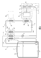
图1是利用以液态形式存储的天然气的能量系统的示意图,其包括根据本发明的与冷却装置相连的第一热交换器和与加热装置相连的第二热交换器;1 is a schematic diagram of an energy system utilizing natural gas stored in liquid form, comprising a first heat exchanger connected to a cooling device and a second heat exchanger connected to a heating device according to the invention;
图2表示图1的变形实例,其中第一热交换器系统布置在比第二热交换器低的高度;Fig. 2 shows a modified example of Fig. 1, wherein the first heat exchanger system is arranged at a lower height than the second heat exchanger;
图3是为气体管道供应气体的再气化终端设备的示意图,其包括本发明的能量系统;Fig. 3 is a schematic diagram of a regasification terminal equipment supplying gas to a gas pipeline, which includes the energy system of the present invention;
图4是包括图2所示热交换器系统的电推动甲烷油轮船的示意图;以及Figure 4 is a schematic diagram of an electrically propelled methane tanker vessel including the heat exchanger system shown in Figure 2; and
图5是现有船上能量系统的示意图。Fig. 5 is a schematic diagram of an existing on-board energy system.
具体实施方式 Detailed ways
图1是使用以液态形式存储在一个或多个罐3中(图中只示出了一个)的天然气1a、1b的能量系统以及热电能单元5的示意图,热电能单元包括发动机7和旋转电机9。Figure 1 is a schematic diagram of an energy system using
旋转电机9可包括由动力电子仪器9c供应动力的交流发电机9a和电马达9b。The rotating
这些旋转电机9都通过冷却装置11冷却,冷却装置11按传统方式包括装备有热交换器11a和11b的管路。因此冷却装置11可确保交流发电机9a、电马达9b和动力电子仪器9c正常工作。These rotating
另外,该能量系统包括输送和处理液化天然气1a和/或天然气蒸汽1b的进给装置13,以供应到热电能单元5的发动机7中(参见图1),或供应到气体管道中(参见图3)。In addition, the energy system comprises a
为了实现这个目的,进给装置13具有加热装置15,加热装置15具有用于加热液化天然气1a和/或天然气蒸汽1b到接近室温的一个或多个热交换器15a、15b,以及压缩天然气蒸汽1b的一个或多个压缩机17。To achieve this, the
因此,进给装置13包括第一管路19,其用于输送存储液化天然气1a的罐3所释放的天然气蒸汽1b。该第一管路19包括至少一个压缩机17和第一加热的热交换器15a。The
此外,为了提供满足热电能单元5需求的附加能量,进给装置13可包括输送液化天然气1a的第二管路21。该第二管路21包括至少一个泵23和第二加热的热交换器15b,该泵23浸在存储液化天然气1a的罐3中。In addition, in order to provide additional energy to meet the needs of the
另外,根据本发明,该能量系统包括第一热交换器25和第二热交换器系统27,第一热交换器25与用于冷却旋转电机9的装置11相连,第二热交换器系统27与加热供应到热电能单元5的液化天然气1a和/或天然气蒸汽1b的装置15相连。Furthermore, according to the invention, the energy system comprises a
第一热交换器系统25可包括一个或多个热交换器25a。类似地,第二热交换器27可包括一个或多个热交换器27a。可以看出为了简化,图中只示出了第一和第二热交换器系统25、27的一个热交换器25a、27a。The first
第一热交换器系统25与第二热交换器系统27相连,以允许热量(在图中用箭头表示)可从冷却装置11传递到加热装置15。因此,使用适于罐3释放的天然气蒸汽1b和从所述罐3中输出的液化天然气1a的部分散热片来降低旋转电机9的工作温度,或更有效地冷却所述电机。The first
第一热交换器系统25和第二热交换器系统27之间的连接通过管29a、29b实现,管29a、29b构成至少一个输送冷却流体的热传递管路29。The connection between the first
热传递管路29形成一个使热传递到冷的天然气蒸汽1b和液化天然气1a的回路,其中天然气蒸汽1b通过第一管路19供应到第一加热的热交换器15a中,液化天然气1a从罐3通过第二管路21经过第二加热的热交换器15b。The
这个热传递回路或管路29包含冷却流体,其成分可根据所需的热性能优化,特别是根据第一和第二热交换器系统25和27的工作温度优化。This heat transfer circuit or
图2是与图1不同的能量系统的示意图,其主要不同是第一热交换器系统25所处高度低于第二热交换器系统27所处的高度。由于第一系统25比第二系统27的温度高,流过第一热交换器系统25的冷却流体和流过第二热交换器27的液体的密度不同,所以这里为冷却流体设置了重力泵。FIG. 2 is a schematic diagram of an energy system different from FIG. 1 , the main difference being that the first
有利地,冷却流体是两相流体,例如氩、氮、或可被液化天然气蒸汽(例如碳氢化合物)冷凝的其他任何制冷剂,其为纯净物或混合物。冷却流体在第一和第二热交换器25、27中的一个或另一个中的相变使热传递管路29的性能得到改进,并减少了构成该管路的元件的尺寸和成本。Advantageously, the cooling fluid is a two-phase fluid, such as argon, nitrogen, or any other refrigerant, pure or in mixture, that can be condensed by liquefied natural gas vapors, such as hydrocarbons. The phase change of the cooling fluid in one or the other of the first and
特别地,第一热交换器系统25可以是蒸发器系统,第二热交换器系统27可以是制冷剂的冷凝器系统。因此,制冷剂在第一热交换器系统25中为气态,在第二热交换器系统27中为液态,可以只在重力的作用下进一步改善其绕着热传递管路29的流动。In particular, the first
可以看出热传递管路29可选择地包括用于制冷剂的一个或多个流速调节元件31(在图中用虚线只示出了一个),以使第一热交换器系统25的热交换能量满足旋转电机9的需求。It can be seen that the
另外,热传递管路29可选择地包括至少一个与辅助热源35(图中用虚线示出)相连的附加热交换器33(图中用虚线示出),该热源例如由水管路(water circuit)、电加热器、或水蒸气源构成。In addition, the
在热传递管路29中包括附加的热交换器33用于蒸发和加热流经第一和第二加热的热交换器15a和15b的天然气蒸汽1b和液化天然气,即使当第一热交换器系统25从用于冷却旋转电机9的冷却装置11中收集的热不足以实现这个目的时。An
此外,冷却装置11可包括空气调节单元37。为了改进旋转电机9温度调节的灵活性,那些电机不需要直接使用通过第一热交换器系统25起作用的散热片,而是通过空气调节单元37。Furthermore, the
因此,这种能量系统可应用于产生电能的系统,特别是使用液化天然气1a或天然气蒸汽1b提供能量的海上(off-shore)燃气终端设备。在这种条件下,旋转电机9主要由产生电能的发电机或交流发电机9a构成。Therefore, this energy system can be applied to a system for generating electric power, especially an off-shore gas terminal facility powered by liquefied
图3示意地表示了包括本发明能量系统的再气化终端设备,其使用以液态形式存储在一个或多个罐3中的天然气1a,罐3用于为气体管路30供应天然气。可以看出,在该图中与图1和图2中相同的元件使用相同的标记。FIG. 3 schematically represents a regasification terminal comprising an energy system according to the invention, using
根据供应管路30高压气体的需求,存储在罐3中的液化气1a通过浸在这个罐3中的泵23被传输到高压泵24,泵24将液化气1a传输到加热装置15(在这种情况下相当于再气化装置),以确保气体在近似室温的温度被传输到管路30之前再气化。According to the demand of the
根据本发明以相同的方式,第一热交换器系统25与第二热交换器系统27相连,以使热能够从冷却装置11传递到加热装置15。In the same manner according to the invention, the first
因此,用于再气化存储在罐3中液态天然气1a的加热装置15提供的散热片用于通过第一和第二热交换器25和27冷却旋转电机9。Therefore, the heating means 15 for regasifying the liquid
需要指出的是,终端设备的热电能单元5的发动机7可选择地通过管路获得存储在罐3中的液化天然气1a和/或天然气蒸汽1b,为了简化在图中未示出该管路。It should be noted that the
该能量系统还可应用于使用以液态形式存储的天然气作为燃料的船。特别的,该系统可应用于运输液化天然气的甲烷油轮。The energy system can also be applied to ships using natural gas stored in liquid form as fuel. In particular, the system can be applied to methane tankers transporting liquefied natural gas.
图4是使用以液态形式存储的天然气作为燃料的电推动甲烷油轮的示意图。Figure 4 is a schematic diagram of an electrically propelled methane tanker fueled by natural gas stored in liquid form.
该甲烷油轮包括图2所示的能量系统,且为了简化只有少量元件在图中示出。然而这种能量系统的结构需要考虑在甲烷油轮船上安装的限制性。The methane tanker includes the energy system shown in Figure 2, and only a few elements are shown in the figure for simplicity. However, the structure of this energy system needs to consider the limitations of installation on board methane tankers.
为了安全起见,构成能量系统的各个装备位于船上两个不同位置。For safety reasons, the individual pieces of equipment that make up the energy system are located in two different locations on board.
气体进给设备13安装在船的货物区域41。相反,推进船的热电能单元5安装在发动机室区域43。The
因此,在货物区域41设置许多用于控制货物并在船推进系统中使用该货物作为燃料的辅助设备,特别是用于控制罐3中压力的辅助设备,用于加热由第一管路19输出的天然气蒸汽1b的辅助设备,用于在加热装置15中加热并在压缩机17中压缩蒸汽的辅助设备,以及用于通过加热装置15蒸发和加热由第二管路21输出的液化天然气1a以作为附加燃料的辅助设备。Therefore, in the
此外,发动机室区域43包括发动机7、交流发电机9a、动力电子仪器9c、和直接驱动或通过连接器、或减速齿轮箱45驱动一个或多个推进器47的电推动马达9a。Furthermore,
为了安全,要求货物区域41(是危险的)位于船的甲板上,并与船的上部结构49保持预定的安全距离,还要求发动机室43中设备的危险部件数量最少,这是因为部分发动机室位于水线的下方很难通风。For safety, it is required that the cargo area 41 (which is dangerous) is located on the deck of the ship and at a predetermined safe distance from the ship's
因此在甲烷油轮中,货物区域41和位于发动机室43内的旋转电机9之间的热传递管路29需要穿过较大的水平距离和高度距离。例如,货物区域41和位于船上部结构49下方的发动机室43之间的水平距离大约为100米(m),货物区域41和发动机室43之间的高度距离大约为30m。Therefore in a methane tanker, the heat transfer piping 29 between the
结果,热传递管路29的管29a和29b的热损失变大。这样可以在热传递管路29中调节安装泵49(在图中用虚线示出),以减少管路中的热损失。As a result, the heat loss of the
然而,利用冷管29a和热管29b之间的流体密度差,货物区域41和发动机室43之间的高度距离可用于使制冷剂仅仅在重力的作用下循环流动,这在制冷剂使第二热交换器系统27作为冷凝器、第一热交换器系统25作为蒸发器时特别有效。冷管29a充满液体,而热管29b充满气体。However, by utilizing the fluid density difference between
例如,如果选择制冷剂为压力大约为2MPa的氩,可以理解氩在那个压力下的液化温度为-140℃。For example, if the selected refrigerant is argon at a pressure of about 2 MPa, it can be understood that the liquefaction temperature of argon at that pressure is -140°C.
在第二热交换器系统27中,氩通过与流经加热的热交换器15a的温度大约为-30℃的冷天然气蒸汽1b接触被冷却,然后通过与流经第二加热的热交换器15b的温度为-160℃的液化天然气1a接触而被液化。In the second
在这种条件下,在冷管29a底部的液柱的液静压大约为0.3MPa。例如,当在第一热交换器系统25出口处的氩的温度大约为0℃以及热管29b充满气体时,相应的液静压大约为0.03MPa。热传递管路29两个分支之间的压力差可用于抑止热管路29中的热损失,而不需要使用泵49,从而增加了可靠性,减少了能量系统的成本。Under this condition, the hydrostatic pressure of the liquid column at the bottom of the
氩的流量大约为3千克每秒(kg/s)可使热以大约600千瓦(KW)的速率在发动机室43和货物区域41之间传递,当管29a和29b各自直径为20厘米(cm)和5cm时,可通过热管29b和冷管29a之间的液静压差抑止热损失。A flow of argon of approximately 3 kilograms per second (kg/s) allows heat to be transferred between the
因此,即使这些管(特别是冷管29b)需要套上厚度为几厘米的绝缘泡沫,将其安装在船上货物区域41和发动机室43之间也不会产生任何附加问题。Therefore, even if these pipes (in particular the
在热传递管路29在正常工作时的平均压力大约为2MPa时,当船没有气体以及整个管路29的温度接近室温时,管路29的尺寸必须适应较高压力(大约5MPa)。While the average pressure of the
另一个解决方案是在热传递管路29(例如在货物区域41)中设置缓冲罐51(在图中用虚线示出),从而限制这种类型的压力增加。为了减小其尺寸,缓冲罐51可选择地被设置外套并保持温度小于室温,或通过供应液化天然气1a的热交换器和蒸发器53保持低温,从而使氩以液态形式存储。Another solution is to place a surge tank 51 (shown in dashed lines in the figure) in the heat transfer line 29 (for example in the cargo area 41 ) so as to limit this type of pressure increase. In order to reduce its size, the
冷却流体的选择不限于氩,也可使用其他流体,或流体的混合物,以提高热传递管路29的热传递能力,或减少其工作压力。The choice of cooling fluid is not limited to argon, and other fluids, or mixtures of fluids, may be used to increase the heat transfer capability of the
除了应用于甲烷油轮,本发明通常可应用于任何使用以液态形式存储的天然气作为燃料的船。特别的,可以看出在这种条件下,即液化天然气的燃料罐与甲烷油轮的罐相比非常小,限制了泄漏到液化天然气中的热,大部分所需的燃料都处于液态形式。为了以相同的动力推进,大量使用可用的散热片,通常为两到三倍多,从而使旋转电机可在更低的温度下工作。在这种条件下,不需要使用在罐中作为散热片的蒸发器,从而可选择省略用于输送气体的第一管路。In addition to application to methane tankers, the invention is generally applicable to any ship that uses natural gas stored in liquid form as fuel. In particular, it can be seen that under such conditions, where the fuel tanks of LNG are very small compared to those of methane tankers, the heat leakage into the LNG is limited, and most of the required fuel is in liquid form. To propel with the same power, the available cooling fins are used extensively, usually two to three times more, allowing the rotating electric machine to operate at a lower temperature. Under such conditions, there is no need to use an evaporator in the tank as a cooling fin, so that the first line for conveying the gas can optionally be omitted.
因此,本发明的能量系统在应用于产生电能的系统或船上时,在加热天然气蒸汽1b和/或液体天然气1a与冷却旋转电机9之间的使用热量方面提供最优方案。Thus, the energy system of the present invention provides an optimal solution in terms of the heat used between heating the
天然气蒸汽1b和/或液化天然气1a提供的散热片与一冷却介质相应,该冷却介质比传统的用于具有分别关闭或打开冷却管路的发动机的水或空气更冷。The cooling fins provided by
因此,通过朝低温移动旋转电机9的工作点(operating point),通过焦耳效应可产生较少的损失。结果增加了这种发动机的效率,使发动机7的能量损耗减少,并减少污染颗粒的释放量。Therefore, by shifting the operating point of the rotary
还可以继续使用工作温度按传统等级(BV、DNV、ABS、等)限定的旋转电机9,但是冷却效率更高。在这种条件下,旋转电机9每单位重量的动力增加,从而结构更紧凑。It is also possible to continue to use a rotating
Claims (15)
Applications Claiming Priority (2)
| Application Number | Priority Date | Filing Date | Title |
|---|---|---|---|
| FR0411328 | 2004-10-25 | ||
| FR0411328A FR2877078B1 (en) | 2004-10-25 | 2004-10-25 | ENERGY SYSTEM USING STORED NATURAL GAS IN LIQUID FORM AND THERMOELECTRIC MACHINES |
Publications (2)
| Publication Number | Publication Date |
|---|---|
| CN1766403A CN1766403A (en) | 2006-05-03 |
| CN100535503C true CN100535503C (en) | 2009-09-02 |
Family
ID=34951192
Family Applications (1)
| Application Number | Title | Priority Date | Filing Date |
|---|---|---|---|
| CNB200510116182XA Expired - Fee Related CN100535503C (en) | 2004-10-25 | 2005-10-25 | Energy system involving natural gas stored in liquid form and thermoelectric engines. |
Country Status (6)
| Country | Link |
|---|---|
| US (1) | US7143598B2 (en) |
| EP (1) | EP1650125B1 (en) |
| JP (1) | JP2006168711A (en) |
| CN (1) | CN100535503C (en) |
| DE (1) | DE602005015658D1 (en) |
| FR (1) | FR2877078B1 (en) |
Families Citing this family (29)
| Publication number | Priority date | Publication date | Assignee | Title |
|---|---|---|---|---|
| KR100864040B1 (en) * | 2001-11-02 | 2008-10-16 | 인터디지탈 테크날러지 코포레이션 | Bidirectional and reverse directional resource reservation setup protocol |
| KR100743905B1 (en) | 2006-05-11 | 2007-08-02 | 삼성중공업 주식회사 | Regasification system of electric propulsion LNG carrier |
| JP5403649B2 (en) * | 2008-07-23 | 2014-01-29 | ジャパンマリンユナイテッド株式会社 | Liquefied gas fuel ship and its bunkering method |
| KR100961867B1 (en) | 2009-10-16 | 2010-06-09 | 대우조선해양 주식회사 | Floating structure with a fuel gas tank |
| JP5494819B2 (en) * | 2010-11-12 | 2014-05-21 | 株式会社Ihi | LNG vaporization equipment |
| KR101447860B1 (en) | 2012-09-21 | 2014-10-07 | 삼성중공업 주식회사 | Ship to carrying reefer container |
| US20140130521A1 (en) * | 2012-11-12 | 2014-05-15 | Fluor Technologies Corporation | Configurations and Methods for Ambient Air Vaporizers and Cold Utilization |
| CN105579680A (en) | 2013-10-18 | 2016-05-11 | 德克萨斯大学系统董事会 | Heat exchanger for thermoelectric power generation with the thermoelectric modules in direct contact with the heat source |
| JP2015123906A (en) * | 2013-12-27 | 2015-07-06 | 川崎重工業株式会社 | Vertical fuel tank and support structure |
| KR20150115126A (en) * | 2014-04-02 | 2015-10-14 | 현대중공업 주식회사 | A Treatment System of Liquefied Gas |
| JP6651370B2 (en) * | 2016-02-05 | 2020-02-19 | 川崎重工業株式会社 | BOG heating system for low temperature liquefied gas |
| CN105673260A (en) * | 2016-03-29 | 2016-06-15 | 成都科力夫科技有限公司 | Gas supply method for dual-fuel automobiles |
| JP6239027B2 (en) * | 2016-04-25 | 2017-11-29 | 三井造船株式会社 | Fuel gas supply system for liquefied gas carrier |
| US10638648B2 (en) | 2016-04-28 | 2020-04-28 | Ge Energy Power Conversion Technology Ltd. | Cooling system with pressure regulation |
| DE102016110625A1 (en) * | 2016-06-09 | 2017-12-14 | Eberspächer Exhaust Technology GmbH & Co. KG | Thermoelectric generator for exhaust systems and contact element for a thermoelectric generator |
| US9894815B1 (en) | 2016-08-08 | 2018-02-13 | General Electric Company | Heat removal assembly for use with a power converter |
| IT201600121441A1 (en) * | 2016-11-30 | 2018-05-30 | Saipem Spa | HEAT PUMP WITH FIRST MOTOR IN CRYOGENIC APPLICATIONS AND REFRIGERANT FLUIDS |
| CN110274157A (en) * | 2018-03-14 | 2019-09-24 | 上海强精金属制品有限公司 | A kind of energy-efficient precision element spraying dynamical system |
| US10941965B2 (en) * | 2018-05-11 | 2021-03-09 | Mitsubishi Electric Us, Inc. | System and method for providing supplemental heat to a refrigerant in an air-conditioner |
| CN109058767B (en) * | 2018-10-08 | 2023-10-03 | 江苏金合能源科技有限公司 | Nuclear reactor steam storage and heating system |
| CN112709930A (en) * | 2019-10-24 | 2021-04-27 | 安瑞科(廊坊)能源装备集成有限公司 | Liquefied natural gas vaporization method and system |
| FR3105462B1 (en) * | 2019-12-20 | 2021-12-03 | Gaztransport Et Technigaz | Method for estimating and adjusting an energy balance of a gas in liquid form contained in a tank |
| US12209710B2 (en) * | 2020-06-09 | 2025-01-28 | Chart Inc. | Cryogenic fluid dispensing system with heat management |
| RU2746579C1 (en) * | 2020-07-31 | 2021-04-15 | Акционерное общество "Промышленные технологии" (АО "Промтехнологии") | Installation for regasification of liquid and supply of fuel to a power plant |
| WO2022075810A1 (en) * | 2020-10-08 | 2022-04-14 | 한국조선해양 주식회사 | Gas treatment system and ship including same |
| CN113639204B (en) * | 2021-06-28 | 2023-07-21 | 厚普清洁能源(集团)股份有限公司 | Constant-temperature air supply PID control method for LNG fuel ship |
| CA3258601A1 (en) * | 2022-06-10 | 2023-12-14 | Plug Power Inc. | Systems and methods for mixing and dispensing gas at a controlled temperature using cryogenic fluid |
| US12241595B1 (en) | 2023-09-05 | 2025-03-04 | Hefei General Machinery Research Institute Co., Ltd. | LNG gas supply systems for ships |
| CN116857088B (en) * | 2023-09-05 | 2023-11-14 | 合肥通用机械研究院有限公司 | LNG gas supply system for ship |
Family Cites Families (3)
| Publication number | Priority date | Publication date | Assignee | Title |
|---|---|---|---|---|
| JPS57167597A (en) * | 1981-04-03 | 1982-10-15 | Hitachi Zosen Corp | Treatment of evaporated gas in lng carrying ship |
| US4574710A (en) * | 1984-11-26 | 1986-03-11 | Pickard John D | Turbo burner coal powered turbine energy system |
| US6053418A (en) * | 1998-01-14 | 2000-04-25 | Yankee Scientific, Inc. | Small-scale cogeneration system for producing heat and electrical power |
-
2004
- 2004-10-25 FR FR0411328A patent/FR2877078B1/en not_active Expired - Fee Related
-
2005
- 2005-10-12 DE DE602005015658T patent/DE602005015658D1/en not_active Expired - Lifetime
- 2005-10-12 EP EP05292129A patent/EP1650125B1/en not_active Expired - Lifetime
- 2005-10-24 US US11/257,494 patent/US7143598B2/en not_active Expired - Fee Related
- 2005-10-25 JP JP2005309756A patent/JP2006168711A/en active Pending
- 2005-10-25 CN CNB200510116182XA patent/CN100535503C/en not_active Expired - Fee Related
Also Published As
| Publication number | Publication date |
|---|---|
| EP1650125B1 (en) | 2009-07-29 |
| FR2877078B1 (en) | 2007-02-02 |
| CN1766403A (en) | 2006-05-03 |
| FR2877078A1 (en) | 2006-04-28 |
| US7143598B2 (en) | 2006-12-05 |
| JP2006168711A (en) | 2006-06-29 |
| EP1650125A1 (en) | 2006-04-26 |
| US20060225448A1 (en) | 2006-10-12 |
| DE602005015658D1 (en) | 2009-09-10 |
Similar Documents
| Publication | Publication Date | Title |
|---|---|---|
| CN100535503C (en) | Energy system involving natural gas stored in liquid form and thermoelectric engines. | |
| JP4343703B2 (en) | LNG regasification apparatus and method on carrier | |
| JP6527249B2 (en) | Vessel containing gas treatment system | |
| KR101750592B1 (en) | A method and arrangement for providing lng fuel for ships | |
| US8499569B2 (en) | System and process for transporting LNG by non-self-propelled marine LNG carrier | |
| CN100579859C (en) | Ship and gas transfer station and method of supplying energy from a ship to a gas transfer station | |
| CN107110427A (en) | Apparatus and method for cooling liquid gas | |
| CN1293747A (en) | Regasification of LNG aboard a transport vessel | |
| WO2013012985A2 (en) | Method and system for combusting boil-off gas and generating electricity at an offshore lng marine terminal | |
| CN113330244B (en) | Space-intensive liquefied natural gas fuel supply system for small ship | |
| JP4738742B2 (en) | Method and apparatus for regasification of LNG on LNG carrier | |
| KR20150121321A (en) | A Treatment System of Liquefied Gas | |
| KR20190008794A (en) | Gas Regasification System and Vessel having the same | |
| KR20060049344A (en) | Energy system using thermoelectric unit and natural gas stored in liquid phase | |
| KR100831946B1 (en) | Regasification method and equipment of liquefied natural gas | |
| KR102282403B1 (en) | Marine Fuel Gas Supply System | |
| WO2022058543A1 (en) | A system for conditioning of lng | |
| KR20220152592A (en) | Gas treatment system of hydrogen carrier | |
| KR101563856B1 (en) | System for supplying fuel gas in ships | |
| JP7743325B2 (en) | Cold heat recovery equipment and ships | |
| CN119013505A (en) | Gas supply system for a high-pressure gas consumer and a low-pressure gas consumer and method for controlling such a system | |
| JP2006504049A (en) | Improved LNG carrier | |
| KR102519041B1 (en) | Fuel Supply System and Ship having the same | |
| KR20150115127A (en) | A Treatment System of Liquefied Gas | |
| JP7725386B2 (en) | Cold heat recovery equipment and ships |
Legal Events
| Date | Code | Title | Description |
|---|---|---|---|
| C06 | Publication | ||
| PB01 | Publication | ||
| C10 | Entry into substantive examination | ||
| SE01 | Entry into force of request for substantive examination | ||
| C14 | Grant of patent or utility model | ||
| GR01 | Patent grant | ||
| C17 | Cessation of patent right | ||
| CF01 | Termination of patent right due to non-payment of annual fee |
Granted publication date: 20090902 Termination date: 20111025 |