CN100524503C - Optical disc device - Google Patents
Optical disc device Download PDFInfo
- Publication number
- CN100524503C CN100524503C CNB2005101069791A CN200510106979A CN100524503C CN 100524503 C CN100524503 C CN 100524503C CN B2005101069791 A CNB2005101069791 A CN B2005101069791A CN 200510106979 A CN200510106979 A CN 200510106979A CN 100524503 C CN100524503 C CN 100524503C
- Authority
- CN
- China
- Prior art keywords
- opening
- optical disc
- pick
- framework
- pallet
- Prior art date
- Legal status (The legal status is an assumption and is not a legal conclusion. Google has not performed a legal analysis and makes no representation as to the accuracy of the status listed.)
- Expired - Fee Related
Links
Images


Classifications
-
- G—PHYSICS
- G11—INFORMATION STORAGE
- G11B—INFORMATION STORAGE BASED ON RELATIVE MOVEMENT BETWEEN RECORD CARRIER AND TRANSDUCER
- G11B33/00—Constructional parts, details or accessories not provided for in the other groups of this subclass
- G11B33/14—Reducing influence of physical parameters, e.g. temperature change, moisture, dust
- G11B33/1406—Reducing the influence of the temperature
- G11B33/1413—Reducing the influence of the temperature by fluid cooling
- G11B33/142—Reducing the influence of the temperature by fluid cooling by air cooling
-
- G—PHYSICS
- G11—INFORMATION STORAGE
- G11B—INFORMATION STORAGE BASED ON RELATIVE MOVEMENT BETWEEN RECORD CARRIER AND TRANSDUCER
- G11B33/00—Constructional parts, details or accessories not provided for in the other groups of this subclass
- G11B33/14—Reducing influence of physical parameters, e.g. temperature change, moisture, dust
-
- G—PHYSICS
- G11—INFORMATION STORAGE
- G11B—INFORMATION STORAGE BASED ON RELATIVE MOVEMENT BETWEEN RECORD CARRIER AND TRANSDUCER
- G11B17/00—Guiding record carriers not specifically of filamentary or web form, or of supports therefor
- G11B17/02—Details
- G11B17/04—Feeding or guiding single record carrier to or from transducer unit
- G11B17/05—Feeding or guiding single record carrier to or from transducer unit specially adapted for discs not contained within cartridges
- G11B17/053—Indirect insertion, i.e. with external loading means
- G11B17/056—Indirect insertion, i.e. with external loading means with sliding loading means
Landscapes
- Optical Head (AREA)
- Feeding And Guiding Record Carriers (AREA)
Abstract
通过不使用风扇的光盘装置的外部空气导入构造,谋求内部冷却性能的提高以及高效率。在光盘装置(1)的框体内部具有:托盘(7)、光盘旋转机构部(10)和拾取器(11),托盘(7)为了装卸光盘(6)可以移动,光盘旋转机构部(10)使光盘在中心部进行旋转,拾取器(11)从中心起在背面侧进行光盘的记录和再生,托盘在中央具有开口(16)、将框体划分成上下。将吸入外部空气用的第一开口(12)设置在从框体的背面侧看在右侧角部附近的背面或侧面、从托盘的下面到拾取器的下面附近的高度上,将排出内部空气用的第二出口(13)设置在从背面侧看在左侧角部附近的背面或侧面、托盘的上面以上的上侧。
Improvement in internal cooling performance and high efficiency are achieved by the external air introduction structure of the optical disc device without using a fan. Inside the frame of the optical disc device (1) are: a tray (7), an optical disc rotation mechanism (10) and a pick-up (11). The tray (7) can move for loading and unloading the optical disc (6), and the optical disc rotation mechanism (10) ) to rotate the disc at the center, the pickup (11) records and reproduces the disc from the center on the back side, and the tray has an opening (16) in the center, dividing the frame into upper and lower parts. The first opening (12) that sucks outside air is used is arranged on the back or side near the right corner from the back side of the frame, on the height from the bottom of the tray to the bottom of the picker, and the inside air will be discharged. The second outlet (13) used is arranged on the back or side near the left corner viewed from the back side, the upper side above the top of the tray.
Description
技术领域 technical field
本发明涉及驱动CD或DVD等光盘媒体的光盘装置。The present invention relates to an optical disc device for driving an optical disc medium such as CD or DVD.
背景技术 Background technique
在现有的塔式或台式计算机用或家庭用录像机用的光盘装置中,不使用风扇而导入外部空气来冷却装置内部的结构的示例在专利文献1和2中有所记载。在专利文献1所述的光盘装置中,与形成装置外面的外罩部件的装置面板相对一侧的面(背面)内,最好在其上端部从设置在靠近光盘旋转方向侧的角部位置的开口部进行排气,从包括外罩部件的外装部件的接触面的间隙将外部空气吸入到装置内。另外,在专利文献2所述的光盘装置中,通过框体和下部的隔壁形成收容光盘驱动装置的光盘收容室,从隔壁下部的框体的侧面(前面·背面)的开口吸入外部空气,经过导向通道、从位于光盘的旋转中心附近的隔壁的开口向光盘收容室引导,从作为框体的光盘收容室的范围的侧面(背面)的开口向外部排出空气。
【专利文献1】特开2003-151259号公报[Patent Document 1] JP-A-2003-151259
【专利文献2】特开2004-241024号公报[Patent Document 2] JP-A-2004-241024
在上述专利文献1和专利文献2中,虽然考虑了光盘装置内部整体的冷却,但对在框体内部尤其是形成高温的拾取器的冷却不是十分有效。In the above-mentioned
本发明的目的是有效地冷却光盘装置的尤其是形成高温的拾取器。本发明的其他目的是一面保持冷却性能一面防止灰尘侵入产生的恶劣影响。It is an object of the present invention to effectively cool a pickup of an optical disk device, especially a high temperature. Another object of the present invention is to prevent adverse effects of dust intrusion while maintaining cooling performance.
发明内容 Contents of the invention
为了解决上述课题的本发明的特征是,具有:框体、托盘、光盘旋转机构部和拾取器,该托盘可从所述框体的前面突出、将光盘装载在上面,该光盘旋转机构部在上述框体内、从托盘的上面附近起被设置在下部,使光盘从上部看向右旋转,拾取器被设置在托盘的下部、从光盘旋转机构部的旋转轴起在上述框体的背面侧,在框体的前后方向移动,托盘在光盘旋转机构部的旋转轴附近与所述拾取器移动的范围上具有开口、上下划分框体的大致矩形板状,在框体上设置第一开口和第二开口,该第一开口是在从框体的背面看至少包括右侧的背面或者与拾取器的前端相比在成为背面侧的右侧的侧面范围内、被设置在从托盘的下面起到所述拾取器的下端附近的高度范围内,该第二开口是在从框体的背面看至少包括左侧的背面或者与拾取器的前端相比在成为背面侧的左侧的侧面范围内、被设置在托盘的上面以上的上部。In order to solve the above-mentioned problems, the present invention is characterized in that it has: a frame, a tray, a disc rotation mechanism part, and a pick-up. In the above-mentioned housing, it is installed in the lower part from the upper surface of the tray, and the optical disk is rotated clockwise when viewed from the upper part. Moving in the front and back direction of the frame, the tray has an opening near the rotation axis of the disc rotation mechanism and the range in which the pickup moves, a roughly rectangular plate shape that divides the frame up and down, and a first opening and a second opening are provided on the frame. Two openings, the first opening is at least including the back of the right side when viewed from the back of the frame or within the range of the side on the right side of the back side compared with the front end of the picker, and is arranged from the bottom of the tray to the bottom of the tray. In the height range near the lower end of the pickup, the second opening is within the range of the left side at least including the left side as viewed from the back of the frame or the left side of the back side compared to the front end of the pickup, It is installed in the upper part above the upper surface of the tray.
这样,由于从背面侧看第一开口位于靠近右侧的角部的背面或侧面、托盘以下的下部,因此,从第一开口进入的外部空气被产生在托盘上部的从背面侧看从光盘向着左侧的角部的内部空气的强流动通过托盘中央的开口吸出地顺畅地移动,并且,由于托盘的下部的任何部分都是低压,因此吸气侧的通风阻力减小。并且,由于第二开口在托盘的上部、位于从背面侧看从上述光盘向着左侧角部的内部空气的强流动集中的位置,因此排气侧的通风阻力减小。因此,通过将吸气和排气用的开口设置在适当的位置这一简单的结构,使外部空气导入量增加,其结果可以提高装置内部的冷却性能。而且,由于第一开口在从背面侧看靠近右侧的角部的背面或侧面、从托盘的下面到拾取器的下端附近的高度上,因此被吸入的外部空气向着光盘的旋转中心、水平地并且逐渐地向着上方流动,大部分到达拾取器,通过向着托盘中央的开口的吸出、使朝向有很大的变化、流入托盘上部。因此,利用简单的构成就可以进行将导入的低温的外部空气基本上没有分散地向尤其是形成高温的拾取器附近引导、吹出的高效率的冷却。In this way, since the first opening is located at the back or side of the corner near the right side and the lower part below the tray when viewed from the back side, the outside air entering from the first opening is generated at the upper part of the tray when viewed from the back side from the optical disc toward the lower part of the tray. The strong flow of the internal air at the left corner moves smoothly through the opening in the center of the tray, and since any part of the lower part of the tray is low pressure, the ventilation resistance on the suction side is reduced. In addition, since the second opening is located on the upper part of the tray where a strong flow of internal air from the disc to the left corner is concentrated when viewed from the rear side, the ventilation resistance on the exhaust side is reduced. Therefore, with a simple structure in which the openings for intake and exhaust are provided at appropriate positions, the amount of external air introduced can be increased, and as a result, the cooling performance inside the device can be improved. And since the first opening is on the back or side of the corner near the right side as viewed from the back side, at a height from the bottom of the tray to the vicinity of the lower end of the pick-up, the outside air sucked in is horizontally toward the center of rotation of the disc. And it gradually flows upward, and most of it reaches the picker, and it flows into the upper part of the tray by sucking out toward the opening in the center of the tray, changing the orientation greatly. Therefore, with a simple configuration, it is possible to perform efficient cooling in which the introduced low-temperature outside air is guided and blown out, especially near the high-temperature pick-up, without being substantially dispersed.
根据本发明,无须冷却风扇就可以高效率地冷却尤其是形成高温的拾取器。According to the present invention, it is possible to efficiently cool, especially, a high-temperature pickup without a cooling fan.
附图说明 Description of drawings
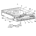
图1是表示本发明的光盘装置的一个实施例的概略结构的分解立体图。FIG. 1 is an exploded perspective view showing a schematic structure of an embodiment of an optical disc device according to the present invention.
图2是表示图1所示的光盘装置的外观立体图。Fig. 2 is a perspective view showing the appearance of the optical disc device shown in Fig. 1 .
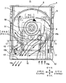
图3是表示图1所示的光盘装置的一部分简略俯视图。Fig. 3 is a schematic plan view showing a part of the optical disc device shown in Fig. 1 .
图4是图3的A-A剖视图。Fig. 4 is a cross-sectional view along line A-A of Fig. 3 .
图5是图3的B-B剖视图。Fig. 5 is a B-B sectional view of Fig. 3 .
图6是表示本发明的光盘装置的其他实施例的外观立体图。Fig. 6 is an external perspective view showing another embodiment of the optical disc device of the present invention.
图7是表示图6所示的光盘装置的一部分简略俯视图。Fig. 7 is a schematic plan view showing a part of the optical disc device shown in Fig. 6 .
图8是图7的C-C剖视图。Fig. 8 is a C-C sectional view of Fig. 7 .
图9是表示本发明的光盘装置的其他实施例的一部分简略俯视图。Fig. 9 is a partial schematic plan view showing another embodiment of the optical disc device of the present invention.
图10是图9的D-D剖视图。Fig. 10 is a D-D sectional view of Fig. 9 .
图11是表示本发明的光盘装置的其他实施例的一部分简略俯视图。Fig. 11 is a partial schematic plan view showing another embodiment of the optical disc device of the present invention.
图12是表示本发明的光盘装置的其他实施例的外观立体图。Fig. 12 is an external perspective view showing another embodiment of the optical disc device of the present invention.
具体实施方式 Detailed ways
以下参照附图、就本发明的实施方式进行说明。Embodiments of the present invention will be described below with reference to the drawings.
【实施例1】【Example 1】
图1是表示本发明的光盘装置的一个实施例的概略结构的分解立体图。图2是表示图1所示的光盘装置的外观立体图,图3是表示去掉其顶盖的一部分简略俯视图,图4是图3的A-A剖视图,图5是图3的B-B剖视图。在本实施例以及以下的实施例中,主要就装载在塔式或台式计算机上的光盘装置1进行说明。FIG. 1 is an exploded perspective view showing a schematic structure of an embodiment of an optical disc device according to the present invention. 2 is a perspective view showing the appearance of the optical disc device shown in FIG. 1, FIG. 3 is a schematic plan view showing a part of its top cover removed, FIG. 4 is a sectional view along A-A of FIG. 3, and FIG. In this embodiment and the following embodiments, the
光盘装置1的框体的上面·侧面被顶盖2覆盖,下面被底盖3覆盖,前面被前面板4覆盖、背面被机械构件5(形成也在前·侧面的稍微内侧延伸的骨架)覆盖,在框体内部、装载光盘6的托盘7被收存在稍上部、进行信号处理以及供给电源的线路基板8被收存在最下部、具有后述的各装置的机械底座9被收存在上述两者之间。托盘7为了装卸光盘6可向前面侧移动,由于左右端面被机械构件5支撑,因此形成将框体划分成上下的结构。在其内侧的开口部16上,光盘旋转机构部10和拾取器11被以固定在机械底座9上的形式设置,光盘旋转机构部10使光盘6(一般从上部看向右方向)旋转,拾取器11具有进行光盘6的信息记录·再生(一般一面从光盘旋转机构部附近向背面侧移动)激光等光学系统。为了进行光盘旋转机构部10和拾取器11的移动·装卸,各装置等通过框体的最下部的线路基板8和柔性印制电路布线板(无图示)连接、进行信号处理·电源供给,从线路基板8向计算机的内部布线通过背面下部的连接部件14连接。另外,在安装在计算机的状态下,从光盘装置1的上·下面以及左右的侧面的前面到内侧中央的部分基本上被向计算机内部的固定部件覆盖。光盘6的记录·再生时,在光盘装置1内,拾取器11的光学系统和光盘旋转机构部10以及线路基板8发热,尤其是在记录速度高或记录张数多的条件下,在发热密度最大的拾取器11上、有可能激光等零件达到保证温度以上。因此,光盘装置1的内部冷却在使整个内部降温的冷却性能的同时,要求提高大幅度降低尤其形成高温的拾取器11的温度的有效的冷却。The top and side of the housing of the
在本实施例中,将外部空气15a的第一开口12设置在从框体的背面侧看在右侧的背面、从内部的托盘7下面到拾取器11下端附近的高度范围内,将内部空气15b的第二开口13设置在从框体的背面侧看在左侧的背面、内部的托盘7上面以上的上部。一般向光盘6进行记录再生时,由于光盘6在托盘7的稍上部旋转、对周围的内部空气15b也产生旋转流,因此在托盘7以上的上部区域、在光盘6的外周侧形成高压的同时,从背面侧看形成从光盘6向着左侧的角部的内部空气15b的强流动。另一方面,在托盘7以下的下部区域上,虽然与光盘6周围在托盘7的中央开口16上部分地连通,但是由于开口16从光盘6的内周向外周延伸、宽度变窄,因此,在区域内形成低于上部的低压。另外,由于上述托盘7上部的内部空气15b的强流动的影响,虽然在开口16的周边形成从背面侧看在右侧、被吸到上部的流动(靠光盘内周)和在左侧、从上部向左侧角部漏出的循环内部空气15b’的流动(靠光盘外周),但是整体只不过是弱流动。In the present embodiment, the
如果将第一开口12和第二开口13如上所述地设置,首先在吸气侧,外部空气15a从第一开口12向着光盘6的旋转中心水平地并且逐渐地向上流动、大部分达到拾取器11,几乎没有分散地顺畅流动,在该部分上,通过被从开口16向上部吸出的流动,使朝向有很大变化并流入托盘上部、与内部空气15b合流地流动。这样从第一开口12向开口16的流动是顺畅的、托盘7的下部被与上部划分、背面或侧面形成低压,因此,吸气侧的通风阻力减小。另外,可以将导入的低温的外部空气15a几乎不分散地向尤其形成高温的拾取器11的附近导入、吹出。另一方面,在排气侧,由于第二开口13位于从托盘的上部的光盘6向着左侧的角部的内部空气15b的强流动集中的位置,因此,可以作为排出空气15c顺畅地从第二开口13流出,排气侧的通风阻力减小。因此,通过将第一开口12和第二开口13设置在适当位置这一简单的构成,可以缩小吸气·排气侧的通风阻力,因此使外部空气导入量增加,其结果,可以提高整个装置内部的冷却性能。同时,将低温的外部空气15a几乎不分散地集中在尤其形成高温的拾取器11上,可以实现高效率的冷却。另外,在该实施例中,在背面,只将第一开口12设置在从背面侧看右侧、将第二开口13设置在左侧,但是在中央或相反侧加大开口的宽度或追加开口进行设置,至少与在上述的原来位置设置开口的作用·效果相同,因此对装置内部的冷却可以得到同样的性能提高和高效率。If the first opening 12 and the
【实施例2】[Example 2]
利用图6~图8、就本发明的光盘装置的其他实施例进行说明。图6是光盘装置的外观立体图,图7是表示去掉图6所示的光盘装置的顶盖的一部分简略俯视图,图8是图7的C-C剖视图。另外,在以下的实施例中通用地将光盘装置的各部件用与第一实施相同的符号表示,动作或结构的说明以与第一实施例的不同点为主体。Another embodiment of the optical disc device of the present invention will be described with reference to FIGS. 6 to 8 . 6 is an external perspective view of the optical disc device, FIG. 7 is a schematic plan view showing a part of the top cover of the optical disc device shown in FIG. In addition, in the following embodiments, the components of the optical disc device are commonly denoted by the same symbols as those in the first embodiment, and the description of operations and configurations will mainly focus on differences from the first embodiment.
在本实施例中,外部空气15a的第一开口12被设置在从框体的背面侧看在靠近右侧的角部的侧面、从内部的托盘7下面到拾取器11下端附近的高度的范围内,内部空气15b的第二开口13被设置在从背面侧看靠近左侧的角部的侧面、内部托盘7上面以上的上侧。与已说明的第一实施例所不同的只是将第一开口12和第二开口13从在背面侧看靠近各个同侧的角部的背面变换到侧面。因此,在与装置内部的各部件的位置关系或原来形成的内部空气15b等的流动状态上与第一实施例没有本质的区别,应该可以得到同样的外部空气导入产生的装置内部冷却的作用·效果。因此,在本实施例中,通过简单的构成可以增加外部空气导入量、提高装置内部的冷却性能的同时,尤其可以对形成高温的部件进行有效的冷却。In this embodiment, the
【实施例3】[Example 3]
利用图9和图10、就本发明的光盘装置的其他实施例进行说明。图9是表示去掉光盘装置的顶盖的一部分简略俯视图,图10是图9的D-D剖视图。Another embodiment of the optical disc device according to the present invention will be described with reference to FIGS. 9 and 10 . FIG. 9 is a schematic plan view showing part of the top cover of the optical disk drive, and FIG. 10 is a sectional view taken along line D-D of FIG. 9 .
在本实施例中,将第一开口12和第二开口13设置在与第一实施例相同的位置上,并且增加了吸气整流部件17和板状的排气整流部件18,吸气整流部件17从第一开口12的内面的开口部到拾取器11的附近管道状地延伸,板状的排气整流部件18从背面侧看、在左侧的托盘7的上面与顶盖2的内面之间从机械构件5起向光盘6的外周延伸。由于吸气整流部件17相当于拾取器11的移动范围的侧面成为开口部,因此,可以将从第一开口12进入的外部空气15a几乎不分散地向尤其形成高温的拾取器11附近引导、吹出,通过排气整流部件18,可以将从托盘7的上部的光盘6向着左侧的角部的内部空气15b的流动更顺畅地向第二开口13的内面的开口部引导。由第一开口12和第二开口13产生的装置内部的冷却作用·效果与第一实施例相同,通过追加的吸气整流部件17和排气整流部件18,这些作用、效果被加强。因此,在本实施例中,通过简单的构成可以增加外部空气导入量、提高装置内部的冷却性能的同时,尤其可以对形成高温的部件进行有效的冷却。In this embodiment, the
【实施例4】【Example 4】
图11是表示本发明的光盘装置的其他实施例的去掉顶盖、从框体的背面侧看右侧后半部分的一部分简略俯视图。Fig. 11 is a schematic plan view showing a part of the right rear half of another embodiment of the optical disc device according to the present invention, with the top cover removed, and viewed from the back side of the housing.
在本实施例中,与第三实施例相同的构成,在向第一开口12的框体内侧延伸的管道状的吸气整流部件17的相当于拾取器11的移动范围的侧面增加可动整流部件19,该可动整流部件19具有被局限于与拾取器11大致相对的范围内的开口部,并且与拾取器11连动地移动。这样,通过将可动整流部件19组合在吸气整流部件17上,可以将从第一开口12进入的低温的外部空气15a几乎不分散地向尤其形成高温的拾取器11附近引导的同时,无论拾取器11移动到任何位置都可以确实地将几乎全部的量吹出。其结果,与第三实施例相比,可以对尤其形成高温的拾取器11进一步高效率地冷却。由于其他构成与第三实施例相同,因此在该实施例中,通过简单的构成可以增加外部空气导入量、提高装置内部的冷却性能的同时,尤其可以对形成高温的部件进行更有效的冷却。In this embodiment, the structure is the same as that of the third embodiment, and the movable rectification is added to the side surface corresponding to the moving range of the pick-up 11 of the pipe-shaped
【实施例5】【Example 5】
图12是表示本发明的光盘装置的其他实施例的外观立体图。Fig. 12 is an external perspective view showing another embodiment of the optical disc device of the present invention.
在本实施例中,与第一实施例同样地、在设置在框体背面的右下方的第一开口12和设置在左上方的第二开口13的外面的开口部上加上防尘用的过滤器20。这样,在第一开口12的过滤器20上可以进行侵入的可能性大的装置运转时的防尘,在第二开口13的过滤器20上虽然侵入量少、但在装置停止时也可以进行防尘。过滤器20是诸如无纺布的薄片,最好是具有均衡的除尘性能和通风阻力,但是如果考虑到通风阻力的增加、只要调整开口面积,则可以适当地确保外部空气导入量,因此,可以得到与第一实施例相同的装置内部冷却性能的提高以及高效率。因此,在本实施例中,通过在吸气·排气用的开口上设置过滤器这一简单的构成,可以一面保持冷却性能、一面防止灰尘侵入产生的恶劣影响。In this embodiment, similar to the first embodiment, dust-proof seals are added to the outer openings of the
本发明可以利用于光盘装置上。The present invention can be applied to an optical disc device.
Claims (7)
Applications Claiming Priority (2)
| Application Number | Priority Date | Filing Date | Title |
|---|---|---|---|
| JP2005147499 | 2005-05-20 | ||
| JP2005147499A JP4557797B2 (en) | 2005-05-20 | 2005-05-20 | Optical disk device |
Publications (2)
| Publication Number | Publication Date |
|---|---|
| CN1866388A CN1866388A (en) | 2006-11-22 |
| CN100524503C true CN100524503C (en) | 2009-08-05 |
Family
ID=37425384
Family Applications (1)
| Application Number | Title | Priority Date | Filing Date |
|---|---|---|---|
| CNB2005101069791A Expired - Fee Related CN100524503C (en) | 2005-05-20 | 2005-09-27 | Optical disc device |
Country Status (5)
| Country | Link |
|---|---|
| US (1) | US7690008B2 (en) |
| JP (1) | JP4557797B2 (en) |
| KR (1) | KR100686665B1 (en) |
| CN (1) | CN100524503C (en) |
| TW (1) | TWI277068B (en) |
Cited By (1)
| Publication number | Priority date | Publication date | Assignee | Title |
|---|---|---|---|---|
| CN104103284A (en) * | 2013-04-12 | 2014-10-15 | 索尼公司 | Disk drive apparatus |
Families Citing this family (8)
| Publication number | Priority date | Publication date | Assignee | Title |
|---|---|---|---|---|
| JP4479662B2 (en) * | 2005-03-10 | 2010-06-09 | パナソニック株式会社 | Optical disk device |
| JP2012507289A (en) | 2008-10-31 | 2012-03-29 | ヤンセン バイオテツク,インコーポレーテツド | Differentiation of human embryonic stem cells into the pancreatic endocrine system |
| WO2010079732A1 (en) * | 2009-01-07 | 2010-07-15 | パナソニック株式会社 | Electronic device |
| TW201133193A (en) * | 2010-03-29 | 2011-10-01 | Hon Hai Prec Ind Co Ltd | Computer enclosure |
| RU2663339C1 (en) | 2010-05-12 | 2018-08-03 | Янссен Байотек, Инк. | Differentiation of human embryo stem cells |
| EP2782099B1 (en) * | 2011-11-15 | 2018-01-03 | Panasonic Intellectual Property Management Co., Ltd. | Onboard optical disk device |
| ES2837763T3 (en) | 2012-12-31 | 2021-07-01 | Janssen Biotech Inc | Culture of human embryonic stem cells in the air-liquid interface for differentiation into pancreatic endocrine cells |
| CN105356313B (en) * | 2015-11-19 | 2017-10-27 | 国家电网公司 | Electric power cabinet |
Citations (1)
| Publication number | Priority date | Publication date | Assignee | Title |
|---|---|---|---|---|
| CN1577211A (en) * | 2003-06-27 | 2005-02-09 | 株式会社日立制作所 | Cooling structure for disk storage device |
Family Cites Families (13)
| Publication number | Priority date | Publication date | Assignee | Title |
|---|---|---|---|---|
| JPH04195885A (en) * | 1990-11-28 | 1992-07-15 | Hitachi Ltd | Optical disk device |
| JPH04358389A (en) | 1991-06-05 | 1992-12-11 | Mitsubishi Electric Corp | Magnetic disk device |
| JPH06236677A (en) * | 1993-02-12 | 1994-08-23 | Ricoh Co Ltd | Optical information recording and reproducing device |
| JP2001155479A (en) * | 1999-11-25 | 2001-06-08 | Sony Corp | Disk unit |
| US6639886B1 (en) * | 2000-07-14 | 2003-10-28 | Visteon Global Technologies, Inc. | Thermal management system in single or multiplayer disk system |
| JP2003151259A (en) * | 2001-11-09 | 2003-05-23 | Hitachi-Lg Data Storage Inc | Optical disk drive |
| US7421720B2 (en) * | 2002-10-10 | 2008-09-02 | Matsushita Electric Industrial Co., Ltd. | Optical disk device |
| JP2004241024A (en) | 2003-02-04 | 2004-08-26 | Shinano Kenshi Co Ltd | Disk drive |
| JP2004259424A (en) * | 2003-02-07 | 2004-09-16 | Shinano Kenshi Co Ltd | Optical disk device |
| JP2005243126A (en) * | 2004-02-25 | 2005-09-08 | Sony Corp | Disk drive device |
| WO2005086169A1 (en) * | 2004-03-05 | 2005-09-15 | Matsushita Electric Industrial Co., Ltd. | Optical disk apparatus |
| TWI238996B (en) * | 2004-09-22 | 2005-09-01 | Benq Corp | Optical disk device |
| JP4324570B2 (en) * | 2005-02-15 | 2009-09-02 | 株式会社日立製作所 | Optical disk device |
-
2005
- 2005-05-20 JP JP2005147499A patent/JP4557797B2/en not_active Expired - Fee Related
- 2005-08-15 TW TW094127742A patent/TWI277068B/en not_active IP Right Cessation
- 2005-09-26 US US11/236,056 patent/US7690008B2/en not_active Expired - Fee Related
- 2005-09-27 CN CNB2005101069791A patent/CN100524503C/en not_active Expired - Fee Related
- 2005-09-29 KR KR1020050090883A patent/KR100686665B1/en not_active Expired - Fee Related
Patent Citations (1)
| Publication number | Priority date | Publication date | Assignee | Title |
|---|---|---|---|---|
| CN1577211A (en) * | 2003-06-27 | 2005-02-09 | 株式会社日立制作所 | Cooling structure for disk storage device |
Cited By (2)
| Publication number | Priority date | Publication date | Assignee | Title |
|---|---|---|---|---|
| CN104103284A (en) * | 2013-04-12 | 2014-10-15 | 索尼公司 | Disk drive apparatus |
| CN104103284B (en) * | 2013-04-12 | 2018-09-18 | 索尼公司 | Magnetic disk drive |
Also Published As
| Publication number | Publication date |
|---|---|
| US7690008B2 (en) | 2010-03-30 |
| TW200641825A (en) | 2006-12-01 |
| KR20060119676A (en) | 2006-11-24 |
| US20060265721A1 (en) | 2006-11-23 |
| TWI277068B (en) | 2007-03-21 |
| JP4557797B2 (en) | 2010-10-06 |
| CN1866388A (en) | 2006-11-22 |
| KR100686665B1 (en) | 2007-02-26 |
| JP2006323955A (en) | 2006-11-30 |
Similar Documents
| Publication | Publication Date | Title |
|---|---|---|
| KR100747316B1 (en) | Electronic apparatus with radiating structure and television game machine with radiating structure | |
| US7800895B2 (en) | Electronic apparatus and sound insulating method thereof | |
| US20140078669A1 (en) | Display Apparatus and Electronic Apparatus | |
| US8238054B2 (en) | Hard disk drive having desiccant member | |
| CN100524503C (en) | Optical disc device | |
| US6880162B2 (en) | Disk drive having an air flow path room | |
| WO2008035699A1 (en) | Electronic device | |
| CN1822206B (en) | CD device | |
| US7914366B2 (en) | Storage apparatus | |
| JP2009059033A (en) | Storage controller | |
| TWI264710B (en) | Disc apparatus | |
| JP2003151259A (en) | Optical disk drive | |
| JP2006108324A (en) | Electronic device | |
| JP2007188599A (en) | Electronic device | |
| JP4724403B2 (en) | Disc player | |
| JP4311274B2 (en) | Optical disk device | |
| CN101331551B (en) | disk device | |
| JP2004241024A (en) | Disk drive | |
| JP2001022899A (en) | Disk and memory card drive device | |
| JP4269865B2 (en) | Optical disk device | |
| JPH04129084A (en) | Disk recording and reproducing device | |
| JP2007004894A (en) | Electronics | |
| JP2009181677A (en) | Optical disk device | |
| JP2012003799A (en) | Optical disk reproducing device | |
| JP2018129110A (en) | Optical disk drive, information expansion device, and information recording device |
Legal Events
| Date | Code | Title | Description |
|---|---|---|---|
| C06 | Publication | ||
| PB01 | Publication | ||
| C10 | Entry into substantive examination | ||
| SE01 | Entry into force of request for substantive examination | ||
| C14 | Grant of patent or utility model | ||
| GR01 | Patent grant | ||
| CF01 | Termination of patent right due to non-payment of annual fee |
Granted publication date: 20090805 Termination date: 20150927 |
|
| EXPY | Termination of patent right or utility model |