EP1168352A2 - Data storage system - Google Patents
Data storage system Download PDFInfo
- Publication number
- EP1168352A2 EP1168352A2 EP01115019A EP01115019A EP1168352A2 EP 1168352 A2 EP1168352 A2 EP 1168352A2 EP 01115019 A EP01115019 A EP 01115019A EP 01115019 A EP01115019 A EP 01115019A EP 1168352 A2 EP1168352 A2 EP 1168352A2
- Authority
- EP
- European Patent Office
- Prior art keywords
- housing
- dust
- station
- filter
- interior
- Prior art date
- Legal status (The legal status is an assumption and is not a legal conclusion. Google has not performed a legal analysis and makes no representation as to the accuracy of the status listed.)
- Withdrawn
Links
Images


Classifications
-
- G—PHYSICS
- G11—INFORMATION STORAGE
- G11B—INFORMATION STORAGE BASED ON RELATIVE MOVEMENT BETWEEN RECORD CARRIER AND TRANSDUCER
- G11B33/00—Constructional parts, details or accessories not provided for in the other groups of this subclass
- G11B33/14—Reducing influence of physical parameters, e.g. temperature change, moisture, dust
- G11B33/1446—Reducing contamination, e.g. by dust, debris
-
- G—PHYSICS
- G11—INFORMATION STORAGE
- G11B—INFORMATION STORAGE BASED ON RELATIVE MOVEMENT BETWEEN RECORD CARRIER AND TRANSDUCER
- G11B17/00—Guiding record carriers not specifically of filamentary or web form, or of supports therefor
- G11B17/22—Guiding record carriers not specifically of filamentary or web form, or of supports therefor from random access magazine of disc records
Definitions
- the present invention relates to a data storage system or library system for storing a number of data recording media.
- the data storing system has a housing that receives a storage station for storing a number of data recording media including CD-ROMs and MDs, for example, a read station for reading out data memorized in each of the data recording media, and a transport station for transporting each of the data recording media between the storage and read stations.
- a storage station for storing a number of data recording media including CD-ROMs and MDs
- a read station for reading out data memorized in each of the data recording media
- a transport station for transporting each of the data recording media between the storage and read stations.
- an optical disk such as DVD capable of memorizing a great number of data per unit area tends to be used for the data recording medium.
- the optical disk however, has an inherent disadvantage that even a small dust if any can deteriorate the reproduction of the data stored in a disk portion underneath the dust and the writing of data into the portion.
- MO disks and DVDs capable of recording a great number of data in a small area, a ratio or efficiency of data reproduction
- the system has a ventilator for exhausting heat generated in the housing enclosing the storage, read, and transport stations.
- the housing is defined with an inlet opening for drawing air into the housing and an outlet opening for exhausting air from the housing.
- a fan is provided near the outlet opening. This allows that air heated within the housing is exhausted through the outlet opening and, in turn, exchanged with fresh air.
- each of the inlet and outlet openings is covered with a mesh.
- a size of each opening defined in the mesh is rather large so that the mesh fails not only to prevent the dust in an exterior of the housing from entering into an interior thereof but also to collect the dust generated at the components in the housing.
- an object of the present invention is to provide a data storage system and a method for preventing dust from entering into the housing and also collecting dust generated within the housing.
- a data storage system has a housing that defines a chamber.
- the chamber receives a storage station for receiving a plurality of recording media and a transport station for transporting the recording medium from and into the storage station.
- the housing is substantially closed so that substantially no dust enters from an exterior into an interior of the housing.
- substantially closed means that no dedicated opening exists for moving air between its interior and exterior. Also, it does not intend to deny any existence of gaps unavoidably formed at connections between panels, one or more doors for opening the interior of the housing or for insertion and extraction of components or parts into and from the housing.
- a dust collector is provided in the interior of the housing.
- the dust collector has a filter for collecting dust and a fan for forming a stream of air that moves past the filter.
- the dust collector has a container with first and second openings, a filter provided at the first opening, and a fan provided at the second opening for forming a stream of air moving past the first and the second openings.
- the substantially closed housing prevents the invasion of dust from its exterior into its interior. Also, the dust generated in the housing is caught by the stream of air formed by the fan and then collected by the filter.
- a performance of the filter i.e., minimum size of the dust to be collected by the filter, should be determined by the size of dust that would cause any recording and reproducing defect when it adheres onto the recording medium.
- Another aspect of the present invention is to provide a method for collecting dust for use with the data storage system.
- the method has steps of providing a substantially closed housing for receiving the storage station and the transport station, providing a filter in the housing for collecting dust in the housing, and forming a stream of air which moves past the filter, so that dust in the housing is caught by the stream of air and then collected by the filter.
- a library system generally indicated by reference numeral 10, which is an embodiment of a data storage system of the present invention.
- the library system 10 has a housing generally indicated by reference numeral 12 for receiving various components or stations required for the storage of data.
- the housing 12 is defined by top wall 14, bottom wall 16, and side wall connecting between the top and bottom walls, 14 and 16.
- the side wall is made up of front panel 18, rear panel 20, and left and right panels 22. Those panels and walls are connected with each other in an airtight fashion to define a substantially closed interior or chamber 24 in the housing 12.
- the front and rear plates, 18 and 20 are hinged on the left or right side wall 22, respectively, so that the components or stations mounted in the housing 12 can be accessed for service and repair. Also, the front panel 18 is provided with inlet and outlet openings defined therein for insertion and extraction of storage medium described after and, if necessary, an operating and/or displaying devices.
- the "substantially closed” means that no dedicated opening, e.g., exhausting opening is defined for causing air to move between the interior and the exterior of the housing 12 but does not deny the existence of the opening closed with openable door or cover for service or repair and for insertion and extraction of components, or unavoidable gaps or clearances leaving between the neighboring panels. This may allow a small amount of dust to enter the interior of the housing 12 through the gaps and when the door is opened, thought, such small amount of dust would not be harmful to the operation of the library system.
- a vertical shaft 26 is provided in the interior 24 of the housing 12.
- a medium transport or handler (transport station) 28 for transporting a storage medium is supported by the shaft 26 so that it moves ups and downs and rotates about the shaft 26.
- Positioned around the media transport 28 are one or more storage units 30, one or more read units 32, and one or more write units 34.
- the storage unit 30 has a number of shelves (not shown) for receiving a number of optical or magnetic recording media including CD-ROMs, DVD-RAMs, and DVD-ROMs, for example.
- the read station 32 is used for reading information recorded in each of the recording media.
- the write station 34 is used for writing and recording information into each of the recording media.
- the read and write stations 32 and 34 may be replaced with an integrated read/write unit capable of reading and writing information from and into each of the recording media.
- the data storage system may have only the read station 32 or the write station 34.
- any one of the storage media received in the storage station 30 is picked up by the handler 28.
- the handler 28 moves up or down along the shaft 26 and, if necessary, rotates about the shaft 26 so as to face the shelf where the recording medium to be extracted therefrom is received.
- the handler 28 holds the recording medium by using a holding mechanism (not shown) thereof.
- the handler 28 again moves up or down along the shaft 26 and, if necessary, rotates about the shaft 26 to face the designated read station 32 to which the recording medium is transferred.
- the handler 28 moves to the designated write station 34 to which the recording medium is transferred.
- the handler 28 extracts the recording medium from the read station 32 or write station 34. Then, the handler 28 moves up or down along the shaft 26 and, if necessary, rotates about the shaft 26 to return the recording medium to the original shelf.
- the library system 10 also includes a dust collector 36 for collecting dust generated by the various components in the housing 12.
- the dust collector 36 has a rectangular, box-like container 48 made of top wall 38, bottom wall 40, front wall 44, rear wall 44, and left and right walls 46, defining an air passage 50 or chamber therein.
- each wall is made from a suitable material such as metal or plastic.
- the top wall 38 and the front wall 42 have respective openings (first openings) 52 and 54.
- the openings 52 and 54 are provided with removable filtering devices 56 and 56, respectively.
- the filtering devices 56 and 58 have frames 60 and 62 made of metal or plastic and filters 64 and 66 retained by the frames 60 and 62, respectively.
- Each of the filters 64 and 66 in particular a mesh size of the filters, is chosen so that the filter collects small dust such as abrasion dust which is generated by contacts of the mechanical components and would cause the reading and/or writing defects of information on the medium.
- the minimum size of the dust required to be collected may range from one to ten microns.
- a filter commercially available from Bridgestone Co. under the tradename of HB-30 is suitably used for the filters 64 and 66.
- the bottom wall 40 which is slanted downward from the front wall 42 to the rear wall 44, has one or more openings 68 defined therein.
- Each of the openings 68 receives a ventilator or electric fan 70 fixedly mounted therein.
- a ventilator or electric fan 70 fixedly mounted therein.
- an electric fan commercially available Sanyo Electric Co. Ltd. under the tradename of 10-R812H402 is used for the electric fan 70.
- the dust collector 36 so constructed is positioned in a certain place in the housing 12.
- the duct collector 36 is fixed at the upper portion of the side wall 22.
- the position of the dust collector 36 is not limited thereto and it may be provided on the inside surface of the top, bottom, front or rear wall.
- the dust collector 36 In operation of the dust collector 36, when the fans 70 are energized, air in the passage 50 is forced out of the openings 68 and then circulated in the housing 12 as shown by a short and long dotted line 72 in Fig. 1.
- the stream of air catches dust generated in the housing 12 and then returns through filters 64 and 66 at the openings 52 and 54, respectively, into the passage 50. This causes the dust to be caught and collected by the filters 64 and 66.
- the filters 64 and 66 are exchanged with new ones at certain intervals.
- the circulation of air 72 causes a diffusion of heat generated at the various components in the housing 12, preventing an unwanted accumulation of heat at certain place or places.
- the housing 12 is substantially closed, which does not prohibit the existence of the possible small gaps between the panels or components of the housing 12 or the existence of openable doors for service and repair. Also, an opening of the front wall 18 and/or rear wall 20 allows an invasion of a small amount of dust into the. interior 24 of the housing 12. Such dust are also caught by the stream air in the housing 12 and then collected by the filters 64 and 66.
- the electric fans 70 are driven so that air in the passage 50 is forced out through the associated opening, it may be energized so that it draws air through the opening.
- the container 48 is provided to support the filters 64 and 66 and the electric fans 70, it may be eliminated from the dust collector 36.
- the filter and fan may be supported by another members so that the fan generates the air stream for catching dust in the housing and then transporting the caught dust through the filter for the removal of the dust.
- substantially no dust is drawn from the exterior into the interior of the housing of the library system. Also, the dust generated in the housing is collected effectively by the filter. This prevents the dust from adhering to the information recording media, which in turn ensures the information to be read from and recorded into the recording media without any defect.
Abstract
Description
- The present invention relates to a data storage system or library system for storing a number of data recording media.
- Conventionally, there have been known various data storing systems or library systems. Typically, the data storing system has a housing that receives a storage station for storing a number of data recording media including CD-ROMs and MDs, for example, a read station for reading out data memorized in each of the data recording media, and a transport station for transporting each of the data recording media between the storage and read stations. Meanwhile, an optical disk such as DVD capable of memorizing a great number of data per unit area tends to be used for the data recording medium. The optical disk, however, has an inherent disadvantage that even a small dust if any can deteriorate the reproduction of the data stored in a disk portion underneath the dust and the writing of data into the portion. In particular, for MO disks and DVDs capable of recording a great number of data in a small area, a ratio or efficiency of data reproduction and data writing depends on the existence of the unwanted dust to a large extent.
- Another data storing system has been proposed in the art. The system has a ventilator for exhausting heat generated in the housing enclosing the storage, read, and transport stations. Specifically, the housing is defined with an inlet opening for drawing air into the housing and an outlet opening for exhausting air from the housing. Also typically a fan is provided near the outlet opening. This allows that air heated within the housing is exhausted through the outlet opening and, in turn, exchanged with fresh air.
- The ventilator is used simply for exhausting heated air from the housing. Also, each of the inlet and outlet openings is covered with a mesh. However, a size of each opening defined in the mesh is rather large so that the mesh fails not only to prevent the dust in an exterior of the housing from entering into an interior thereof but also to collect the dust generated at the components in the housing.
- This allows the dust in the housing to be placed on the data recording media, which causes defects in data reproduction and recording. Also, the ratio of defect in the data reproduction and recording is increased with time in proportion to the increase of dust in the housing.
- Therefore, an object of the present invention is to provide a data storage system and a method for preventing dust from entering into the housing and also collecting dust generated within the housing.
- Accordingly, a data storage system has a housing that defines a chamber. The chamber receives a storage station for receiving a plurality of recording media and a transport station for transporting the recording medium from and into the storage station. The housing is substantially closed so that substantially no dust enters from an exterior into an interior of the housing.
- The "substantially closed" means that no dedicated opening exists for moving air between its interior and exterior. Also, it does not intend to deny any existence of gaps unavoidably formed at connections between panels, one or more doors for opening the interior of the housing or for insertion and extraction of components or parts into and from the housing.
- Further, according to the first aspect of the present invention, a dust collector is provided in the interior of the housing. The dust collector has a filter for collecting dust and a fan for forming a stream of air that moves past the filter.
- According to the second aspect of the present invention, the dust collector has a container with first and second openings, a filter provided at the first opening, and a fan provided at the second opening for forming a stream of air moving past the first and the second openings.
- With the' data storage system of the present invention, the substantially closed housing prevents the invasion of dust from its exterior into its interior. Also, the dust generated in the housing is caught by the stream of air formed by the fan and then collected by the filter. For this purpose, a performance of the filter, i.e., minimum size of the dust to be collected by the filter, should be determined by the size of dust that would cause any recording and reproducing defect when it adheres onto the recording medium.
- Another aspect of the present invention is to provide a method for collecting dust for use with the data storage system. The method has steps of providing a substantially closed housing for receiving the storage station and the transport station, providing a filter in the housing for collecting dust in the housing, and forming a stream of air which moves past the filter, so that dust in the housing is caught by the stream of air and then collected by the filter.
-
- Fig. 1 is a schematic perspective view of a library system of the present invention;
- Fig. 2 is a cross-sectional view taken along line II-II in Fig. 1;
- Fig. 3 is a perspective view of a dust collector received in the housing of the library system in Fig. 1; and
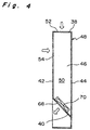
- Fig. 4 is a cross-sectional view taken along line IV-IV in Fig. 3.
- Like reference numerals designate like parts throughout the drawings.
- With reference to the drawings, a specific embodiment of the present invention will be described hereinafter. It should be noted that although various directional terms including "top" and "bottom", for example, in order to improve the understanding of the invention, the present invention is not limited by those terms.
- Referring to Fig. 1, there is shown an overview of a library system generally indicated by
reference numeral 10, which is an embodiment of a data storage system of the present invention. Also, as shown in Fig. 2, thelibrary system 10 has a housing generally indicated byreference numeral 12 for receiving various components or stations required for the storage of data. Thehousing 12 is defined bytop wall 14,bottom wall 16, and side wall connecting between the top and bottom walls, 14 and 16. The side wall is made up offront panel 18,rear panel 20, and left andright panels 22. Those panels and walls are connected with each other in an airtight fashion to define a substantially closed interior orchamber 24 in thehousing 12. The front and rear plates, 18 and 20, are hinged on the left orright side wall 22, respectively, so that the components or stations mounted in thehousing 12 can be accessed for service and repair. Also, thefront panel 18 is provided with inlet and outlet openings defined therein for insertion and extraction of storage medium described after and, if necessary, an operating and/or displaying devices. - The "substantially closed" means that no dedicated opening, e.g., exhausting opening is defined for causing air to move between the interior and the exterior of the
housing 12 but does not deny the existence of the opening closed with openable door or cover for service or repair and for insertion and extraction of components, or unavoidable gaps or clearances leaving between the neighboring panels. This may allow a small amount of dust to enter the interior of thehousing 12 through the gaps and when the door is opened, thought, such small amount of dust would not be harmful to the operation of the library system. - As best shown in Fig. 2, a
vertical shaft 26 is provided in theinterior 24 of thehousing 12. A medium transport or handler (transport station) 28 for transporting a storage medium is supported by theshaft 26 so that it moves ups and downs and rotates about theshaft 26. Positioned around themedia transport 28 are one ormore storage units 30, one ormore read units 32, and one ormore write units 34. Thestorage unit 30 has a number of shelves (not shown) for receiving a number of optical or magnetic recording media including CD-ROMs, DVD-RAMs, and DVD-ROMs, for example. Theread station 32 is used for reading information recorded in each of the recording media. Also, thewrite station 34 is used for writing and recording information into each of the recording media. The read and writestations read station 32 or thewrite station 34. - Descriptions will be made to the operation of the
library system 10 so constructed. Any one of the storage media received in thestorage station 30 is picked up by thehandler 28. For this purpose, thehandler 28 moves up or down along theshaft 26 and, if necessary, rotates about theshaft 26 so as to face the shelf where the recording medium to be extracted therefrom is received. Then, thehandler 28 holds the recording medium by using a holding mechanism (not shown) thereof. For reproducing the information recorded in the medium, thehandler 28 again moves up or down along theshaft 26 and, if necessary, rotates about theshaft 26 to face the designatedread station 32 to which the recording medium is transferred. On the other hand, for recording information on the extracted recording medium, thehandler 28 moves to the designatedwrite station 34 to which the recording medium is transferred. After the completion of the reproduction or the recording, thehandler 28 extracts the recording medium from the readstation 32 or writestation 34. Then, thehandler 28 moves up or down along theshaft 26 and, if necessary, rotates about theshaft 26 to return the recording medium to the original shelf. - The
library system 10 also includes adust collector 36 for collecting dust generated by the various components in thehousing 12. As best shown in Figs. 3 and 4, thedust collector 36 has a rectangular, box-like container 48 made oftop wall 38,bottom wall 40,front wall 44,rear wall 44, and left andright walls 46, defining anair passage 50 or chamber therein. Preferably, each wall is made from a suitable material such as metal or plastic. - The
top wall 38 and thefront wall 42 have respective openings (first openings) 52 and 54. Theopenings removable filtering devices filtering devices frames frames filters filters - The
bottom wall 40, which is slanted downward from thefront wall 42 to therear wall 44, has one ormore openings 68 defined therein. Each of theopenings 68 receives a ventilator orelectric fan 70 fixedly mounted therein. Preferably, an electric fan commercially available Sanyo Electric Co. Ltd. under the tradename of 10-R812H402 is used for theelectric fan 70. - The
dust collector 36 so constructed is positioned in a certain place in thehousing 12. In this embodiment, as shown in Figs. 1 and 2 theduct collector 36 is fixed at the upper portion of theside wall 22. However, the position of thedust collector 36 is not limited thereto and it may be provided on the inside surface of the top, bottom, front or rear wall. - In operation of the
dust collector 36, when thefans 70 are energized, air in thepassage 50 is forced out of theopenings 68 and then circulated in thehousing 12 as shown by a short and long dottedline 72 in Fig. 1. The stream of air catches dust generated in thehousing 12 and then returns throughfilters openings passage 50. This causes the dust to be caught and collected by thefilters filters air 72 causes a diffusion of heat generated at the various components in thehousing 12, preventing an unwanted accumulation of heat at certain place or places. - As described above, the
housing 12 is substantially closed, which does not prohibit the existence of the possible small gaps between the panels or components of thehousing 12 or the existence of openable doors for service and repair. Also, an opening of thefront wall 18 and/orrear wall 20 allows an invasion of a small amount of dust into the.interior 24 of thehousing 12. Such dust are also caught by the stream air in thehousing 12 and then collected by thefilters - Although the
electric fans 70 are driven so that air in thepassage 50 is forced out through the associated opening, it may be energized so that it draws air through the opening. - Also, the
container 48 is provided to support thefilters electric fans 70, it may be eliminated from thedust collector 36. In this instance, the filter and fan may be supported by another members so that the fan generates the air stream for catching dust in the housing and then transporting the caught dust through the filter for the removal of the dust. - As can be seen from above, according to the present invention, substantially no dust is drawn from the exterior into the interior of the housing of the library system. Also, the dust generated in the housing is collected effectively by the filter. This prevents the dust from adhering to the information recording media, which in turn ensures the information to be read from and recorded into the recording media without any defect.
Claims (3)
- A data storage system, comprising:a housing defining a chamber therein for a storage station for receiving a plurality of recording media and a transport station for transporting the recording medium from and into the storage station, the housing being substantially closed so that substantially no dust enters from an exterior into an interior of the housing; anda dust collector provided in the interior of the housing, the dust collector having a filter for collecting dust and a fan for forming a stream of air that moves past the filter.
- A data storage system, comprising:a housing defining a chamber therein for a storage station for receiving a plurality of recording media and a transport station for transporting the recording medium from and into the storage station, the housing being substantially closed so that substantially no dust enters from an exterior into an interior of the housing; anda dust collector provided in the interior of the housing, the dust collector having a container with first and second openings, a filter provided at the first opening, and a fan provided at the second opening for forming a stream of air moving past the first and the second openings.
- A method for collecting dust for use with a data storage system with a storage station for storing information media and a transport station for transporting each of the information media from one place to another, comprising the steps of:providing a housing for receiving the storage station and the transport station, the housing being substantially closed so that substantially no dust enters from an exterior of the housing into an interior of the housing;providing a filter in the housing for collecting dust in the housing; andforming a stream of air which moves past the filter, so that dust in the housing is caught by the stream of air and then collected by the filter.
Applications Claiming Priority (2)
| Application Number | Priority Date | Filing Date | Title |
|---|---|---|---|
| JP2000186231 | 2000-06-21 | ||
| JP2000186231A JP2002008363A (en) | 2000-06-21 | 2000-06-21 | Data preservation system and powder recovering method for the same |
Publications (2)
| Publication Number | Publication Date |
|---|---|
| EP1168352A2 true EP1168352A2 (en) | 2002-01-02 |
| EP1168352A3 EP1168352A3 (en) | 2002-05-08 |
Family
ID=18686427
Family Applications (1)
| Application Number | Title | Priority Date | Filing Date |
|---|---|---|---|
| EP01115019A Withdrawn EP1168352A3 (en) | 2000-06-21 | 2001-06-20 | Data storage system |
Country Status (3)
| Country | Link |
|---|---|
| US (1) | US20020018425A1 (en) |
| EP (1) | EP1168352A3 (en) |
| JP (1) | JP2002008363A (en) |
Cited By (2)
| Publication number | Priority date | Publication date | Assignee | Title |
|---|---|---|---|---|
| WO2006036140A1 (en) * | 2004-09-27 | 2006-04-06 | Spectra Logic Corporation | Method and apparatus for adsorbing molecules from an atmosphere inside and enclosure containting multiple data storage devices |
| US7445654B2 (en) | 2004-09-27 | 2008-11-04 | Spectra Logic Corporation | Method and apparatus for adsorbing molecules from an atmosphere inside an enclosure containing multiple data storage devices |
Families Citing this family (1)
| Publication number | Priority date | Publication date | Assignee | Title |
|---|---|---|---|---|
| DE102004014149B4 (en) * | 2004-03-20 | 2007-01-25 | Hydac Filtertechnik Gmbh | filter means |
Citations (8)
| Publication number | Priority date | Publication date | Assignee | Title |
|---|---|---|---|---|
| US4385333A (en) * | 1980-08-04 | 1983-05-24 | International Memories, Inc. | Magnetic disc drive system |
| JPS5897147A (en) * | 1981-12-04 | 1983-06-09 | Sony Corp | Helical scanning type video tape recorder |
| JPS63124282A (en) * | 1986-11-13 | 1988-05-27 | Nec Corp | Optical disk device |
| JPH0279288A (en) * | 1988-09-16 | 1990-03-19 | Nec Corp | Head disk assembly for magnetic disk device |
| JPH02132673A (en) * | 1988-11-11 | 1990-05-22 | Matsushita Electric Ind Co Ltd | Automatic changer |
| JPH02276056A (en) * | 1989-04-17 | 1990-11-09 | Mitsubishi Electric Corp | Large capacity optical disk storage device |
| US5418763A (en) * | 1992-07-16 | 1995-05-23 | Hitachi, Ltd. | Disc recording system |
| JPH07272476A (en) * | 1994-04-01 | 1995-10-20 | Ricoh Co Ltd | Optical recording/reproducing sub system and optical recording/reproducing library apparatus |
Family Cites Families (1)
| Publication number | Priority date | Publication date | Assignee | Title |
|---|---|---|---|---|
| US5673029A (en) * | 1996-02-15 | 1997-09-30 | Orbitron Computer System, Inc. | Apparatus for cooling a memory storage device |
-
2000
- 2000-06-21 JP JP2000186231A patent/JP2002008363A/en active Pending
-
2001
- 2001-06-20 US US09/885,619 patent/US20020018425A1/en not_active Abandoned
- 2001-06-20 EP EP01115019A patent/EP1168352A3/en not_active Withdrawn
Patent Citations (8)
| Publication number | Priority date | Publication date | Assignee | Title |
|---|---|---|---|---|
| US4385333A (en) * | 1980-08-04 | 1983-05-24 | International Memories, Inc. | Magnetic disc drive system |
| JPS5897147A (en) * | 1981-12-04 | 1983-06-09 | Sony Corp | Helical scanning type video tape recorder |
| JPS63124282A (en) * | 1986-11-13 | 1988-05-27 | Nec Corp | Optical disk device |
| JPH0279288A (en) * | 1988-09-16 | 1990-03-19 | Nec Corp | Head disk assembly for magnetic disk device |
| JPH02132673A (en) * | 1988-11-11 | 1990-05-22 | Matsushita Electric Ind Co Ltd | Automatic changer |
| JPH02276056A (en) * | 1989-04-17 | 1990-11-09 | Mitsubishi Electric Corp | Large capacity optical disk storage device |
| US5418763A (en) * | 1992-07-16 | 1995-05-23 | Hitachi, Ltd. | Disc recording system |
| JPH07272476A (en) * | 1994-04-01 | 1995-10-20 | Ricoh Co Ltd | Optical recording/reproducing sub system and optical recording/reproducing library apparatus |
Non-Patent Citations (6)
| Title |
|---|
| PATENT ABSTRACTS OF JAPAN vol. 007, no. 198 (P-220), 2 September 1983 (1983-09-02) -& JP 58 097147 A (SONY KK), 9 June 1983 (1983-06-09) * |
| PATENT ABSTRACTS OF JAPAN vol. 012, no. 380 (P-769), 12 October 1988 (1988-10-12) -& JP 63 124282 A (NEC CORP), 27 May 1988 (1988-05-27) * |
| PATENT ABSTRACTS OF JAPAN vol. 014, no. 274 (P-1061), 13 June 1990 (1990-06-13) -& JP 02 079288 A (NEC CORP), 19 March 1990 (1990-03-19) * |
| PATENT ABSTRACTS OF JAPAN vol. 014, no. 360 (P-1088), 3 August 1990 (1990-08-03) -& JP 02 132673 A (MATSUSHITA ELECTRIC IND CO LTD), 22 May 1990 (1990-05-22) * |
| PATENT ABSTRACTS OF JAPAN vol. 015, no. 041 (P-1160), 31 January 1991 (1991-01-31) -& JP 02 276056 A (MITSUBISHI ELECTRIC CORP), 9 November 1990 (1990-11-09) * |
| PATENT ABSTRACTS OF JAPAN vol. 1996, no. 02, 29 February 1996 (1996-02-29) -& JP 07 272476 A (RICOH CO LTD), 20 October 1995 (1995-10-20) * |
Cited By (2)
| Publication number | Priority date | Publication date | Assignee | Title |
|---|---|---|---|---|
| WO2006036140A1 (en) * | 2004-09-27 | 2006-04-06 | Spectra Logic Corporation | Method and apparatus for adsorbing molecules from an atmosphere inside and enclosure containting multiple data storage devices |
| US7445654B2 (en) | 2004-09-27 | 2008-11-04 | Spectra Logic Corporation | Method and apparatus for adsorbing molecules from an atmosphere inside an enclosure containing multiple data storage devices |
Also Published As
| Publication number | Publication date |
|---|---|
| US20020018425A1 (en) | 2002-02-14 |
| EP1168352A3 (en) | 2002-05-08 |
| JP2002008363A (en) | 2002-01-11 |
Similar Documents
| Publication | Publication Date | Title |
|---|---|---|
| US6208484B1 (en) | Recirculation filter for use in a disk drive | |
| EP0263932B1 (en) | Disk file including a filtration system | |
| KR930002562B1 (en) | Dust tight storage cabinet apparatus for use in clean rooms | |
| JPH0565958B2 (en) | ||
| CN100524503C (en) | Optical disc device | |
| JPS58501881A (en) | Disk cartridge loading mechanism | |
| EP0013472A1 (en) | Removable cover for video disk and a video disk and player system for use with a disk having a removable cover | |
| US4771412A (en) | Cooling device for optical information recording and reproducing apparatus | |
| US4268878A (en) | Gas circulation and filtration apparatus for magnetic disc recording systems | |
| EP1168352A2 (en) | Data storage system | |
| EP0391555A2 (en) | Disk drive including recirculating filter assembly | |
| JP2001307474A (en) | Disk device | |
| US4377830A (en) | Combination magnetic disk storage device and filter system | |
| US7836463B2 (en) | Optical disk drive comprising dust removing apparatus | |
| US20230048789A1 (en) | Archival data storage library | |
| US7295398B2 (en) | High speed cleanup of removable storage device | |
| JPH0258789A (en) | Optical disk device | |
| US7092202B1 (en) | Enhanced airflow conditioning system for removable data storage cartridge | |
| JPH03125370A (en) | Auto-changer | |
| CN218851107U (en) | Enterprise data information early warning platform | |
| JP6656965B2 (en) | Air cleaner | |
| JP2510185Y2 (en) | Disk library device | |
| JPH0279288A (en) | Head disk assembly for magnetic disk device | |
| JPH04182980A (en) | Optical disk cartridge | |
| US20040076085A1 (en) | Data library with robotically retrievable filter cartridge |
Legal Events
| Date | Code | Title | Description |
|---|---|---|---|
| PUAI | Public reference made under article 153(3) epc to a published international application that has entered the european phase |
Free format text: ORIGINAL CODE: 0009012 |
|
| AK | Designated contracting states |
Kind code of ref document: A2 Designated state(s): AT BE CH CY DE DK ES FI FR GB GR IE IT LI LU MC NL PT SE TR |
|
| AX | Request for extension of the european patent |
Free format text: AL;LT;LV;MK;RO;SI |
|
| PUAL | Search report despatched |
Free format text: ORIGINAL CODE: 0009013 |
|
| AK | Designated contracting states |
Kind code of ref document: A3 Designated state(s): AT BE CH CY DE DK ES FI FR GB GR IE IT LI LU MC NL PT SE TR |
|
| AX | Request for extension of the european patent |
Free format text: AL;LT;LV;MK;RO;SI |
|
| AKX | Designation fees paid | ||
| REG | Reference to a national code |
Ref country code: DE Ref legal event code: 8566 |
|
| STAA | Information on the status of an ep patent application or granted ep patent |
Free format text: STATUS: THE APPLICATION IS DEEMED TO BE WITHDRAWN |
|
| 18D | Application deemed to be withdrawn |
Effective date: 20021109 |