CN100504050C - Rotary mechanism, machine comprising same or also including balancing mechanism - Google Patents
Rotary mechanism, machine comprising same or also including balancing mechanism Download PDFInfo
- Publication number
- CN100504050C CN100504050C CNB2004800246561A CN200480024656A CN100504050C CN 100504050 C CN100504050 C CN 100504050C CN B2004800246561 A CNB2004800246561 A CN B2004800246561A CN 200480024656 A CN200480024656 A CN 200480024656A CN 100504050 C CN100504050 C CN 100504050C
- Authority
- CN
- China
- Prior art keywords
- rotor
- chamber
- rotating machinery
- positioning disk
- guiding device
- Prior art date
- Legal status (The legal status is an assumption and is not a legal conclusion. Google has not performed a legal analysis and makes no representation as to the accuracy of the status listed.)
- Expired - Fee Related
Links
Images


Classifications
-
- F—MECHANICAL ENGINEERING; LIGHTING; HEATING; WEAPONS; BLASTING
- F01—MACHINES OR ENGINES IN GENERAL; ENGINE PLANTS IN GENERAL; STEAM ENGINES
- F01C—ROTARY-PISTON OR OSCILLATING-PISTON MACHINES OR ENGINES
- F01C1/00—Rotary-piston machines or engines
- F01C1/22—Rotary-piston machines or engines of internal-axis type with equidirectional movement of co-operating members at the points of engagement, or with one of the co-operating members being stationary, the inner member having more teeth or tooth- equivalents than the outer member
-
- F—MECHANICAL ENGINEERING; LIGHTING; HEATING; WEAPONS; BLASTING
- F01—MACHINES OR ENGINES IN GENERAL; ENGINE PLANTS IN GENERAL; STEAM ENGINES
- F01C—ROTARY-PISTON OR OSCILLATING-PISTON MACHINES OR ENGINES
- F01C1/00—Rotary-piston machines or engines
Abstract
A rotary mechanism (10) has an annular (chamber12) defined by an inner wall (16) of housing (11). A symmetrical two lobed rotor (15) has opposing side faces (21a,21b) a longitudinal axis between apices (22). A drive shaft (50) eccentrically rotates rotor by a block (51) and slot (52) receprocating arrangement and a second supporting means (53). The centre of the rotor follows a circular orbit in the chamber (12). The apices (22) continuously sweep the inner wall (16) creating cavities (25) of successively increasing and decreasing volumes with associated fluid inolet and exhaust port (31, 35).
Description
Technical field
The present invention relates to a kind of rotating machinery, this rotating machinery has two-lobe rotor, thus described rotor in closed chamber by the fluid in the eccentric drive compression or the described chamber that expands.
Background technique
Rotating machinery all has application in the various machines that include oil hydraulic pump, gas compressor, gas expander and rotary engine etc.
Many dissimilar rotary machines of moving at pump, compressor, decompressor and rotary engine of being used for have been proposed.Most of known rotary machines have been obtained limited operational success in arbitrary above-mentioned application, but also do not have arbitrary rotary machine to be suitable for all successfully moving in all these are used.
A kind of specific rotary machine comprises two-lobe lenticular rotor (two-lobe lenticular rotor) or the blade that is installed in rotation in the annular cavity, and described annular cavity has the shelly structure of circle.Rotatablely moving of two-lobe rotor must be guided subtly, remains with the sliding contact of chamber inner wall and sealing with the top of guaranteeing two-lobe rotor to contact, thereby continuously changes spatial volume between rotor and the chamber wall.The inlet that enters in the chamber allows fluid to enter, and fluid is discharged by outlet under the compression of rotor.
In a kind of known rotary machine, open-ended crank extends through the end cap and the support rotor of chamber.Thereby driving mechanism rotating crank rotary rotor in chamber.Rotor motion is by the gear train channeling conduct that is installed in lenticular rotor one end.The problem of this design is that this gear train is not enough to bear high vibration stress and the load that acts on mechanically in running.
Above-mentioned this rotary machine has eccentric rotor rotated barycenter, and this will produce inclination or tractive along a direction naturally.Even increased the rigidity of chamber housing and introduced the rotation counterweight, have the somewhat complex design of gear train guiding device or introduce arbitrarily upsetting mechanical symmetric design and still can not offsetting common mechanical tilt of other in rotor one side such as those, can disequilibrium when therefore moving.
Another kind of known rotary machine uses the axle that extends through groove, and wherein, the correlation of groove and axle is that the reciprocatingly slide guided rotor of axle in groove rotates in chamber prejudicially.But, this design is structurally too fragile, can not bearing pump, the continuous shaking stress under normal operating condition such as compressor, decompressor, motor.Sometimes each axle of fully loaded that all will carry the motion rotor in each circulation of rotor can not sustain and repeat load and shear deformation can take place.
With regard to internal-combustion engine, only there is the revolution design of Wankel engine (Wankel) successfully to be applied in the internal-combustion engine.But, even if Wankel engine also has deficiency,, make it only be suitable under the situation of high speed rotating, using and being only applicable to Lightweight Vehicles because three protruding leaf rotors in the epitrochoid chamber cause low thermodynamic efficiency.Because at the upper dead center at motor maximum compression place, rotor stays two and has the not little gap of compressed fuel across the epitrochoid chamber and between rotor and chamber wall, so compression ratio is low.Under the situation of low speed rotation, the contact loss of rotor and chamber especially merits attention.Three sealings of protruding leaf rotor in the chamber of this shape are also particularly difficult.
In all rotary machines, particularly very difficult owing to keeping good cavity seal, and caused thermodynamic efficiency low.Because many known rotary machines have complicated rotor, have complicated chamber shape usually, so the tip seal of top end need extend more or less from rotor thereupon.In many cases, described tip seal self will bear load during rotor operation, and this makes them be easy to wearing and tearing and leaks.For example the supplementary features of gear train and groove have increased the region quantity that escape of liquid may take place, and because the size and the location of these supplementary features possibly can't be provided with Sealing effectively.The shape that is appreciated that rotor and chamber is complicated more, and cavity seal will run into big more difficulty.In addition, the comparatively complicated design with a greater number assembly is more expensive, and make and safeguard understand more difficult.
Usually, rotary machine also can face other thermodynamic disadvantages, promptly is difficult to cooled rotor effectively.And the cooling problem may cause being difficult to keep the integrity (integrity) of fabricated metals (metal), particularly the integrity of the fabricated metals of the rotor that may reach a high temperature.
Mechanical part is the common problem that causes machinery to block such as the wearing and tearing of the rotor drive of gear train and tank systems especially.One of them main cause is exactly for numerous designs, and moving assembly is forced to bear big point load or carrying uneven load, and this can cause the part of assembly to wear and tear more severely than another part.Like this, the bigger load that applies on weak spot can further produce the vibration that wearing and tearing are worsened.
Therefore need a kind of improved rotating machinery, it can carry out the operation of available heat mechanics as motor, so that the compression ratio that is enough to drive various vehicles to be provided.This mechanism should make economy, and sealing and wearing and tearing are good, and carrying full load easily when as operations such as pump, compressor, motors.
Summary of the invention
According to the present invention, a kind of rotating machinery is provided, comprising:
Housing, described housing define the roughly ringwise closed chamber with inwall;
Two-lobe symmetric rotor, described rotor have the longitudinal center's axis between the top of described rotor; Described rotor is arranged in the following manner in the described chamber and also rotates prejudicially to slide in described chamber: the inswept continuously described inwall in described top, thus between each protruding leaf and described inwall, produce the cavity that volume increases in succession and reduces; Wherein, described rotor is installed on the axle that extends through at least one end of described chamber, described axle supports first guiding device, described first guiding device is to be mounted to the block that can move back and forth with respect to described epitrochanterian elongated slot (elongated slot), thus, described block and described axle allow described rotor to slide and rotate prejudicially;
Isolated ingress port and discharge port are used for fluid being infeeded described cavity and discharging from described cavity; And
Second guiding device, described second guiding device and described first guiding device interact, to guide described rotor and guarantee that described top keeps continuous seal to contact with described inwall in running, make described centre of rotor move along the circular trace in the described chamber, wherein, the central axis of the described chamber of misalignment of described second guiding device, the axle of described installation rotor is a single shaft, it extends through the opposite end of described chamber, and the central axis of the described chamber of misalignment.
Preferably, described guiding device is a guidance set, and described directing assembly constitutes the contact surface with coupling, thereby the contact load between the guidance set that is bonded with each other is evenly distributed along described guidance set.
Preferably, described guidance set comprises: circular positioning disk, and described positioning disk is installed at least one end of described annular cavity; And corresponding circular depressions, it is positioned at a side of described rotor, with ccontaining described positioning disk; Wherein, described recess has the initial point that is positioned at described centre of rotor, and bigger than described positioning disk, rotates around described positioning disk to allow described circular depressions.
According to the present invention, a kind of rotating machinery is provided, comprising:
Housing, described housing define the roughly ringwise closed chamber with inwall;
Two-lobe symmetric rotor, described rotor have the longitudinal center's axis between the top of described rotor; It is interior to rotate prejudicially in described chamber that described rotor is arranged on described chamber in the following manner: the inswept continuously described inwall in described top, thus between each protruding leaf and described inwall, produce the cavity that volume increases in succession and reduces; Wherein, described rotor is installed on the single shaft of the opposite end that extends through described chamber, described axle supports first guiding device, described first guiding device limits by being mounted to the block that moves back and forth with respect to described epitrochanterian elongated slot, thus, described block and axle allow described rotor eccentricity ground to rotate;
Isolated ingress port and discharge port are used for fluid being infeeded described cavity and discharging from described cavity; And
Second guiding device, described second guiding device and described first guiding device interact, contact so that guide described rotor and guarantee that described top seals with described inwall continuously at run duration, make described centre of rotor move along the circular trace in the described chamber, wherein, described second guiding device comprises:
Circular positioning disk, described positioning disk is installed at least one end of described annular cavity; And
Corresponding circular depressions, it is positioned on the side of described rotor, with ccontaining described positioning disk; Wherein, described recess has the initial point that is positioned at described centre of rotor place, and bigger than described positioning disk, rotates around described positioning disk to allow described circular depressions.
According to the present invention, a kind of rotating machinery is provided, comprising:
Housing, described housing define the roughly ringwise closed chamber with inwall;
Two-lobe symmetric rotor, described rotor have the longitudinal center's axis between the top of described rotor; It is interior to rotate prejudicially in described chamber that described rotor is arranged on described chamber in the following manner: the inswept continuously described inwall in described top, thus between each protruding leaf and described inwall, produce the cavity that volume increases in succession and reduces; Wherein, described rotor is installed on the single shaft of the opposite end that extends through described chamber, described axle supports first guiding device, described first guiding device limits by being mounted to the block that moves back and forth with respect to described epitrochanterian elongated slot, thus, described block and axle allow described rotor eccentricity ground to rotate;
Isolated ingress port and discharge port are used for fluid being infeeded described cavity and discharging from described cavity; And
Second guiding device, described second guiding device and described first guiding device interact, contact so that guide described rotor and guarantee that described top seals with described inwall continuously at run duration, make described centre of rotor move along the circular trace in the described chamber, wherein, described second guiding device comprises:
Circular positioning disk, described positioning disk is installed at least one end of described annular cavity and departs from the central axis of described chamber; And
Corresponding circular depressions, it is positioned on the side of described rotor, with ccontaining described positioning disk; Wherein, described recess has the initial point that is positioned at described centre of rotor place, and bigger than described positioning disk, carries out finite movement to allow described rotor on described positioning disk.
Description of drawings
The invention will be further described by way of example with reference to the accompanying drawings, in the accompanying drawing:
Fig. 1 is that its rotor is positioned at the upper dead center of chamber according to rotating machinery first embodiment's of the present invention schematic plan;
Fig. 2 shows the counterclockwise situation of 30 ° of displacements of rotor of the mechanism of Fig. 1;
Fig. 3 shows the counterclockwise situation of 60 ° of displacements of rotor of the mechanism of Fig. 1;
Fig. 4 shows the counterclockwise situation of 90 ° of displacements of rotor of the mechanism of Fig. 1;
Fig. 5 shows the counterclockwise situation of 135 ° of displacements of rotor of the mechanism of Fig. 1;
Fig. 6 is the schematic cross sectional views along this rotating machinery first embodiment of the line 6-6 of Fig. 1, and the corresponding sectional view shown in the 1-1 along the line is Fig. 1;
Fig. 7 is that its rotor is positioned at the upper dead center of chamber according to rotating machinery second embodiment's of the present invention schematic plan;
Fig. 8 shows the counterclockwise situation of 30 ° of displacements of rotor of the rotating machinery of Fig. 7;
Fig. 9 shows the counterclockwise situation of 60 ° of displacements of rotor of the rotating machinery of Fig. 7;
Figure 10 shows the counterclockwise situation of 90 ° of displacements of rotor of the rotating machinery of Fig. 7;
Figure 11 shows the counterclockwise situation of 135 ° of displacements of rotor of the rotating machinery of Fig. 7;
Figure 12 is the schematic cross sectional views along this rotating machinery second embodiment of the line 12-12 of Fig. 7, and the corresponding sectional view shown in the 7-7 along the line is Fig. 7;
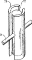
Figure 13 a is embodiment's the stereogram of the rotor of this rotating machinery, and it shows the profile of block and groove;
Figure 13 b is the stereogram of the geometric profile of embodiment's block of this rotating machinery and groove;
Figure 13 c is the stereogram of the geometric profile of embodiment's another block of this rotating machinery and groove;
Figure 13 d shows two kinds of possibilities of the shape of housing cavity according to an embodiment of the invention;
Figure 14 is the sectional view as second embodiment of air compressor;
Figure 15 is the sectional view of counterweight shown in Figure 14;
Figure 16 is the plan view of counterweight;
Figure 17 illustrates the volume of this rotating machinery and Shaft angle function relation embodiment's plotted curve;
Figure 18 is the zoomed-in view of this rotating machinery apex rotor against housing.
Embodiment
Fig. 1 and Fig. 7 show two embodiments that are suitable for the rotating machinery 10 that uses in multiple application, and described application comprises oil hydraulic pump, gas compressor, gas expander and rotary engine.In these two embodiments, mechanism 10 has the rotor that is arranged in the closed chamber, this rotor eccentricity ground rotates to increase and to reduce the size in chamber inner sealing space in regular turn, thereby (promptly according to ingress port and the outlet position of port and port operation, port is as open valve or timing valve), introduce fluid in the chamber and make fluid expansion or compressed fluid by ingress port.Fluid is discharged by the outlet port then.
Two embodiments shown in the accompanying drawing show rotating machinery 10 and comprise having the roughly housing 11 of annular chamber 12.Chamber 12 is limited by inner chamber wall 16 and housing end plug 13, the structure difference of end cap 13 (seeing Fig. 6 and Figure 12) between the different embodiments.Each end cap 13 back shaft neck is supported on the axle in the interior supporting member 14 of described lid.Though the block shaft (block shaft) or the split axle (split shaft) that extend from each lid have been shown among the embodiment disclosed herein, but should be appreciated that the characteristic of rotor (with particular reference to second embodiment) can make this mechanism just be enough to operation by the single block shaft that only extends through an end cap 13.
Be provided with two-lobe lenticular rotor in the chamber 12.This rotor is in shape about vertical major axis 20 and vertical minor axis 23 symmetries.The intersection point of major axis and minor axis defines centre of rotor axis 30.The vertical major axis 20 of rotor and the connecting part of two protruding leaves 21, promptly apex rotor 22 intersects.The protruding leaf 21 of these two symmetries comes to a point towards the top inwardly along major axis 20.Be outward extended with spring-loaded tip seal (not shown) from the top, and spring-loaded tip seal is suitable for continuous inwall 16 against chamber.The spring-loaded characteristic of tip seal has remedied may be because the defective of chamber wall or the micro-gap that design causes between (bridge) chamber wall 16 and the top 22.
Rotor is suitable for rotation prejudicially in chamber 12, slide with the form of circular conchoid (circular-conchoidal) simultaneously, make the top inswept continuously and contact with described inner wall sealing along inner chamber wall 16, produce the enclosed cavity 25 adjacent with each protruding leaf 21, like this, rotor 15 rotates the volume that all can make described enclosed cavity each time and increases in succession and reduce.Tip seal at top end prevents between chamber 25 escape of liquid to take place.The volume-variation of closed chamber 25 owing to rotor 15 along with the rotation in chamber the circular conchoid path of process.That is to say that centre of rotor axis 30 is not the position of fixing with respect to chamber 12, but center on the central axis 32 eccentric initial points (origin) 31 that are provided with of chamber, along the circular trace operation that is called centrode 33.
In first split axle embodiment shown in Fig. 1 to Fig. 6, initial point 31 lays respectively between the axle center (axial centre) 46 and 47 of first split axle 41 and second split axle 44.To second d-axis (straight shaft) embodiment shown in Figure 12, initial point 31 is positioned between the axle center 57 of the central axis 32 of chamber 12 and single shaft (single shaft) 50 at Fig. 7.
The centrode initial point 31 of rotor departs from the central axis 32 of chamber, makes rotor slide with respect to chamber and rotates prejudicially, thereby produce two relative, volume continually varying cavitys.The sectional view of Fig. 2-5 and Fig. 8-11 shows first and second embodiments' of this mechanism the geometrical relationship of assembly respectively.Especially, it clearly show that the centrode 33 and the initial point 31 thereof of rotor.
Described chamber is described to roughly ringwise.Though annular cavity can be satisfied the demand fully, some position on its rotation path may apply undesirable load on top and especially tip seal.In order to reduce this load, the interior shape of chamber can not made circular, but makes the shape by the accurate path that practical top limited of rotor, promptly circular conchoidal.In this case, this shape and circular not essence difference, however, even the chamber by such formation makes the problem that may occur when having varying loading on load on the tip seal and the tip seal can not overcome at least also and can minimize substantially.
Fig. 1 and Fig. 7 show ingress port that separates 34 and the discharge port 35 on the inner chamber wall 16.The minor variations of distance can change the interior hydrodynamic pressure of chamber and the timing of this mechanism between these two ports, thereby makes it be adapted at using in the different application.The expectation such as motor, pump, compressor, decompressor etc. according to this mechanism is used, and can determine this arbitrarily modification.Although there are some overlap joints to allow between the port, usually at any time a cavity only to a port open.
When work, remove nonfluid through precompression, otherwise fluid can enter in the cavity under the effect of cavity that is increased by size and the caused vacuum effect of consequent suction gradient (vacuum effect).In case the size of cavity begins to reduce, then inlet is closed, and discharge port opens, to discharge fluid under compressive state.This process occurs in the half way around of rotor, and this discharging can be referred to as pulsation.Therefore there are two pulsation in each rotation of rotor.Usually do not need inlet valve (inlet valve), because the vacuum that the cavity that enlarges produces is enough to suck fluid.Can use one-way valve at the discharge port place, enter chamber in case the fluid stopping body refluxes.
Alternatively, after entering the chamber of expansion, a certain amount of pre-compressed fluid closes inlet.Make the size of chamber become big by the fluid applied pressure, thereby the moment of torsion that drives one or more is provided.In case the size of cavity begins to reduce, then a port is opened, and allows to discharge the fluid (expandedfluid) that expands.
Contact and prevent that fluid from leaking from cavity 25 in order to ensure the sealing of inswept top and inner chamber wall, accurately the rotor rotation of off-centre is very important in the chamber.Though spring-loaded tip seal allows some tolerance, when the design top, must be noted that to make the inswept in the clear inwall in top, promptly contact inwall just or the interval is arranged with inwall; Rather than forcibly with the inwall effect, this will cause top wearing and tearing.Rotating machinery first and second embodiments' described here DESIGNED FEATURE provides accurate eccentric rotary path in essence, and the top can be inswept in the clear along this path.
In addition, although rotor eccentricity ground rotates, the split axle embodiment's of this mechanism the assembly that is bonded with each other allows its evenly and reposefully rotary load of bear rotor.In d-axis embodiment, in fact all loads all are subjected to by single link stopper bearing, and making no longer needs to be used to be bonded with each other the complexity supporting device (bearing arrangement) of assembly.
First and second embodiments of this mechanism all have drive unit; Perhaps, under being applied as the situation of motor or gas expander, this mechanism has driven device.Two embodiments also have guiding device.In first embodiment, split axle is simultaneously as drive unit and guiding device.Special-purpose guiding device is arranged in d-axis embodiment.In these two embodiments, driving/driven device and/or guiding device make centre of rotor move along the circular trace in the described chamber (being centrode).
To first embodiment (split axle embodiment) shown in Figure 6, drive unit comprises first and second blocks and shaft device (block and shaft arrangement) at Fig. 1.First rectangular block 40 is fixed on the end of first split axle 41 of mechanism 10, and is mounted in first elongated slot 42 in an end face 24a of rotor and moves reciprocatingly.First elongated slot 42 is parallel with the minor axis 23 of rotor, and arranges along the minor axis 23 of rotor.Axle center 46 (Fig. 2) defines the central axis of first split axle 41.Second rectangular block 43 is installed on the end of second split axle 44, and is set in place in second elongated slot 45 (Fig. 2) on the 24b of rotor other end.Second elongated slot and first elongated slot are rectangular, that is, and and along major axis 20 location.Axle center 47 is central axis of second split axle 44.First and second split axles 41 and 44 in the aforementioned end cap 13 that is supported in chamber 12 by axle journal are arranged to, and first split axle 41 is coaxial with the central axis 32 of chamber, and another split axle is second split axle, 44 off center axis 32.Side-play amount depends on the size of chamber, and it is determined by the distance of two between centers and the profile of rotor.The sectional view of this mechanism shown in Fig. 6 clearly show that the split axle of skew and vertical block and slot device.
When first split axle 41 or second split axle 44 rotates or both when rotating simultaneously, come to drive rotor 15 by the linear reciprocating motion of groove on corresponding block around chamber.The interaction simultaneously of the rotation of axle and described split axle force rotor 15 with slip and off-centre but controlled way around chamber 12 motions, thereby make the top with the inswept inner chamber wall 16 of close clearance.
Because two grooves are with the right angle setting, block 40 and 43 accurately is positioned at rotor in the chamber effectively, thereby forces inwall 16 operations of top 22 along chamber.Protruding leaf 21 is in succession near adjacent inner chamber wall part or this part further away from each other from the positions in whole rotary course.
Fig. 1 to Fig. 5 shows the situation of rotor half way around, at first is 30 ° interval, then between Fig. 4 and Fig. 5 and to turn back to Fig. 1 be 45 ° interval.
Fig. 1 shows the situation in when beginning rotation, and this moment, fluid entered the first enclosed cavity 25a, and rotor is closed cavity 25a and entered the mouth 34 and outlet 35.The rotor of this position is positioned at upper dead center.Particularly, first rectangular block 40 is positioned at the top of first groove 42, and second block 43 is positioned at the center of second groove 45, equates with the distance of the second groove end part interval.The mutual rotation of one or two in the block shaft (block shaft) 41 and 44 forces groove to slide on its corresponding block, thereby rotor 15 is rotated in chamber 12 prejudicially.
Fig. 2 to Fig. 5 shows the rotation and first and second grooves the reciprocatingly sliding on its associated blocks of rotor 15.For clarity, ingress port and discharge port have been omitted among Fig. 2 to Fig. 5, but can imagine, by second enclosed cavity 25 of chamber bottom in Fig. 2 and the adjacent formation of the second protruding leaf 21b, enter the second cavity 25b by ingress port under the vacuum pressure of fluid in the cavity 25b that enlarges.
Simultaneously, the fluid adjacent with the protruding leaf 21a of the first rotor is forced to discharge by discharge port 35 among the first enclosed cavity 25a.Therefore, this mechanism sucks, compresses in each changes and discharges fluid twice, that is to say twice pulsation of revolution.Therefore, the operation that occurs on the operation that occurs on rotor one side and rotor opposite side is identical, and 180 ° phase difference is only arranged.
Fig. 7 to Figure 12 shows the second embodiment of the present invention (single shaft embodiment).All adopt identical reference character with the similar feature of first embodiment.Second embodiment comprises single block shaft 50, and this single block shaft 50 has longitudinal axis 57, and vertically extends through this mechanism from an end cap 13 to another end cap of chamber (right).This single block shaft 50 extends through described rotor, and supports the driving block 51 that is positioned at rotor 15 inside.
Drive unit among this embodiment only comprises the driving block 51 that is arranged in the elongated slot 52 that is used to reciprocatingly slide.Groove 52 aligns along the major axis of rotor, and vertically runs through the width extension of rotor.When axle 50 rotated, groove moved on driving block 51, thereby rotor eccentricity ground is moved around described chamber.The central axis 32 that axle 50 self departs from chamber to be providing the displacement of rotor with respect to chamber, thereby produces the long-pending enclosed cavity of transfiguration.
This embodiment comprises the guiding device that guides movable rotor around described chamber prejudicially.This guiding device comprises the positioning disk 53 of two circles, and described positioning disk 53 is outstanding to the inside of chamber 12 from the end cap 13 of housing.Figure 12 shows described outstanding positioning disk 53 best.Positioning disk 53 can be integrally formed with end cap 13, perhaps can make separately and be connected to end cap more independently.Stepped part 54 is separated positioning disk and the spill annulus 55 that centers on each positioning disk.
Two end face 24a of rotor and 24b be provided with corresponding with positioning disk 53 but greater than the circular depressions 56 of positioning disk.Circular depressions 56 on the arbitrary end of rotor is used for corresponding positioning disk 53 on the ccontaining adjacent end cap 13.Because the diameter of circular depressions 56 is greater than positioning disk 53, so rotor 15 can move around positioning disk, but because the restriction of the diameter difference between positioning disk and the circular depressions is arranged, so displacement is limited.Described diameter difference is determined by the difference of skew between the central axis 32 of the axle center 57 of axle 50 and chamber.This distance is determined by the variable volume of the cavity that is used for application-specific again.Because the synthesis result of eccentric shaft and rotor displacement will be guaranteed the top inwall of inswept chamber continuously, so the midpoint between the axle center of the central axis that is centered close to chamber of circular discs 53 and axle 50.Therefore, the central axis 32 of chamber is also departed from the center of positioning disk 53, and is the point identical with the initial point 31 of rotor center track.Especially, positioning disk 53 and positioning disk and the recess combined guided effect that produces that is bonded with each other is the center with track origin 31, thereby allows to make rotor rotation under the situation that does not apply any remarkable load on the guidance set.
The accurate conchoid path that the limit movement of being arranged by the device combination of guiding device and block and groove has produced apex rotor, in this path, the top is with mode inswept continuously (circumspect) inner chamber wall 16 of sealing contact.In fact, come a dispensing rotor around the proper motion of the chamber resulting path of the inswept all the time inwall in top by the structure of combined guiding device.What certainly can understand is that guiding device can only use a positioning disk to move, but positioning disk preferably all is set on each end cap, because the rotor motion of balance and symmetry is provided like this.
Figure 12 shows the positioning disk 53 in the circular depressions 56 that is placed in rotor.The positioning disk stepped part 54 of the wall by the adjacent circular recess is come the motion of restrict rotor.
Fig. 7 to Figure 11 shows the half way around of rotor, and it is identical with shown in first embodiment at interval.That is, Fig. 8,9,10 and 11 shows the rotor from 30 °, 60 °, 90 ° of upper dead center neutral position shown in Figure 7 displacements and 135 ° respectively.Can see that in order to obtain the expected path of rotor rotation, block shaft 50 itself is mounted to the center of departing from positioning disk 53 and the central axis 32 of chamber 12.
Fig. 8 to Figure 11 schematically shows the rotor 15 that rotates in chamber 12, drive reciprocatingly sliding on the block 51 by elongated slot 52 in rotation and drive this motion.Circular depressions 56 by the rotor of positioning disk 53 restriction has further limited this motion.As discussing in first embodiment, rotor center (axle line 30 places therein) is moved along the centrode 33 around initial point 31.The major axis among Fig. 8 to Figure 11 (also being applicable to Fig. 2 to Fig. 5) and the intersection point of minor axis have been represented rotor center 30.When rotor rotates in chamber prejudicially, rotor center 30 shown in Fig. 8 to Figure 11 for 33 moving along the path.Can also see that the centrode 33 of rotor aligns with one heart with positioning disk 53.
The advantage that positioning disk brings is that it allows straight block shaft (straight block shaft) to extend through whole chamber from an end cap 13 to another end cap, and allows this to carry all rotating loads by the dish that only is used as guiding device.Eliminate all rotor tilt like this, and reduced the vibration in the mechanism.Owing to do not need heavy duty roller bearings to adjust axle deviation and the play that causes by the rotor that tilts, so the design of this mechanism is more simpler than known design.Less parts and simpler design have reduced the overall manufacture cost of this mechanism.
In addition, circular discs by the circular depressions guiding provides the coefficient of waste (wear factor) between a kind of rotor and the chamber thorough minimized device, its reason is that positioning disk that engages one another and the contact load between the recess are along described positioning disk and recess equiblibrium mass distribution.That is to say, on positioning disk 53 circumference be a little uniform wear, and on the inner circumference of circular depressions 56 to have a few also be uniform wear.Its reason is, two assemblies have coupling or consistent contact surface, and promptly circle rotates in than great circle one.In other words, the time that all keeps identical of having a few on the positioning disk with circular depressions contact, thus wearing and tearing are reduced to negligible degree, and occurring wear distributes equably around assembly.Such as other the inconsistent devices such as round member in having the groove of parallel wall is not so just, and wherein some on member or groove points contact the time of different length respectively with cell wall or member, and this causes fault at run duration the most at last.
The device of block shown in two embodiments of Fig. 1 to Figure 12 and elongated slot shows the axle that is connected with block, and described block is rectangular profile and slides in the rectangle groove of correspondence.The surface of block and the internal surface of groove are machining surface, and it has close tolerance (close tolerance) to guarantee farthest and to transmit reposefully the driving energy of the axis of rotation.The internal surface of groove can be used to reduce friction along the bearing surface setting.
The rotor of Figure 13 a shows the corresponding support contour of when initial position axle bumper piece and groove.But, block and support contour are also nonessential to be rectangular profile, but can comprise the geometrical shape of other couplings.For example, Figure 13 b and Figure 13 c show cylindrical piston shaft/bearing surface profile and hexagon (cylindrical hexagonal) profile respectively.In these embodiments, axle 71 extends through block 72, and described block 72 slides in the corresponding bearing surface 73 that is shaped in rotor.The profile of block/slot can adopt provides any geometrical shape that remains the bearing surface constant uniform sliding contact, that be complementary with machining surface.Can select the contour shape of rotor/slot, to adapt to processing restriction and/or the spatial constraints of this rotating machinery in different application better.
In addition, for many machines, the structure of this mechanism's sub-circular is an optimal design.But, the shape of this mechanism can be made amendment, as long as this modification is more suitable for particular machines.In a second embodiment, eccentric shaft and the block in corresponding groove and the combined guided influence that is contained in circular discs in the corresponding concave part, place, Pit cover end in the rotor side surface have realized by rotor and the corresponding conchoidal path that chamber shape realized.The change in shape of any all can cause moving and the change in shape in path in these parameters.The shape of rotor and housing profile also can be made amendment to be fit to specific function better.
For example, the shape of housing can be made for annular or conchoidal.When the inwall of the inswept chamber of apex rotor, the housing molding of conchoidal is for closely following apex rotor.This shape provides the minimum clearance between any point place apex rotor and chamber wall.Figure 13 d shows the conchoidal chamber profile 77 overlapping with annular cavity profile 78.Although the conchoidal profile is roughly circular contour, the difference of these two kinds of profiles is obvious.Other modification comprises the shape that changes housing end plug and the shape of rotor cover.These modifications can adapt to the function of the machine that comprises this rotating machinery better, and can for example improve support loading, increase the gap, change flow velocity, optimize port timing, spill firing chamber (recessedcombustion chamber) etc. is provided.
Different with many known rotating machinerys, two embodiments of this mechanism are crossed drive unit owing to all rotating loads and are distributed equably, so can bear load easily and realize good balance.Further to be reduced to negligible degree in order vibrating, can to use the rotation counterweight to come balancing rotor effectively.The reason that rotor oscillation takes place is that the barycenter of each commentaries on classics rotor of rotor all can rotate twice.In order to offset this vibration, introduced balanced controls and rotated with same rotational speed and same number of revolutions with barycenter with rotor, promptly whenever turn around this balanced controls of rotor and axle rotate twice.This can recently realize by the transmission of using 1:2.
Figure 14 to Figure 16 shows this Equilibrator, and it shows the embodiment as the straight shaft rotary mechanism 10 of air compression machine operation.In air compressor shown in Figure 14, this rotating machinery 10 is driven by live axle 90, and is limited by side cover 91.Live axle 90 rotates on main supporting member 98, and rotor 93 slides on sliding bearing 99 with respect to live axle 90.The housing 92 of this rotating machinery surrounds rotor 93, and supports the radiating fin 94 that radially extends from housing 92.Annular keeper 95 is arranged in the circular depressions 96 of rotor 93, and spill supporting (recessed bearing) (ring) and scraper ring is provided.Described oil ring is identical with the effect of oil ring in piston type or the wankel rotary engine, is used for controlling cold oil and enters compression chamber from internal rotor.Described annular keeper rotates around described positioning disk, with the motion path in conjunction with axle/block and rotor generation rotor.The rotor recesses 96 of annular keeper is rotated around fixing positioning disk 97.
These balanced controls comprise the counterweight 63 with hole 67, and this counterweight 63 is installed on the rotor shaft 50 in the mode that axle journal supports, and axle 50 this counterweight that whenever turns around just takes two turns around axle 50.The quality that Figure 16 shows this counterweight 63 is derived from the semicircular structure of 67 belows, hole.
Drive counterweight 63 by this way and can make counterweight (in unison) rotation harmoniously, and offset because the balance forces that the barycenter of rotor 15 causes.
With regard to this rotating machinery is used as air compressor, have only the significant big positive displacement air compressor of vibration just really to need balanced controls.The air compressor of small capacity, the vibration that for example each circulation all is lower than the air compressor of 300cc can not reach significant degree usually.
Whether decision uses balanced controls also to depend on the quality and the material thereof of rotor.Compare with heavier rotor, lighter rotor is difficult for producing significant vibration.
But, generally speaking, compare with the rotating machinery of other types, the vibration that this rotating machinery produces is lower, is easy to just can obtain fabulous balance.This be because, compare with the motion eccentric rate (eccentricity) of the piston barycenter that for example has similar capacity, the motion eccentric rate of this rotor centroid is extremely low.
The geometrical shape of this rotating machinery makes it reducing mechanism to vibrate, to reduce wearing and tearing, to eliminate high stress areas, and generally speaking, it can prolong the life-span of this mechanism usually.And, under d-axis embodiment's situation, two main work packages are only arranged in the chamber of this mechanism, the groove that promptly on block, slides and around the recess of fixing positioning disk motion, thus reduced the complexity of this mechanism.
In order to obtain optimum efficiency, according to the application of this rotating machinery, can be by the dynamics analysis of this rotating machinery being calculated the profile geometries of housing and rotor.
By the dynamic analysis of this rotating machinery, can derive the math equation that is used to describe and produce thus rotor and housing geometrical shape.This class math equation can be implemented by producing the computer software programs of making rotor and the required coordinate of housing (coordinate).At least utilize the expected value of maximum chamber radius and first and housing off-centring distance, can calculate geometric profile.Expectation gap between rotor and the housing also can be used for how much and calculates.
One of this rotating machinery is characterised in that, it produces harmonious circulation (harmonic cycle), makes that thus the charging volume in the processing procedure is the simple sinusoidal function of Shaft angle (shaft angle) θ.From mathematics, the diagram of simple vibration motion and diagram similar, that a bit move along a circle are equivalent to a sinusoidal curve.The simple sinusoidal characteristic of the expansion-compression cycle that is produced by this rotating machinery has been simplified the design and the analysis of the machine that comprises this mechanism.The function that can be used as Shaft angle such as the volume of handling (volume processed), transmission pressure and the such performance characteristics of moment of torsion calculates.Figure 17 show this rotating machinery at it when the air compressor, as the sine function of the volume of Shaft angle θ ° function.Based on this mechanism, the simple harmonious characteristic of the simple character of this mechanism and the thing followed thereof (harmonicnature) is expected to reflect well the performance and the efficient of machine.
Except apex seal, the suitable seal technology also is applied to other parts of rotating machinery.In single shaft embodiment, circular depressions 56 is applicable to the oil sealing of ccontaining circle, and circular oil sealing is more effective when sealing, and than the easier location of non-circular Sealing.The size of the small size of positioning disk and corresponding rotor recesses makes that sealing is easier, and has bigger flexibility when being designed to different application in mechanism.When this mechanism when the motor, using gases sealing technique at an easy rate in its capacity.Should be appreciated that in this application of this mechanism, the sealing grid (grid) of top and side seal and described port and valve are worked harmoniously, with sealed combustion chamber effectively.
This rotating machinery as among the embodiment of air compressor, can be installed the seals of cheap and simple at it.Use Sealing to produce three-dimensional effective seal grid, to increase the thermomechanics and the working efficiency of compressor in the side of top end and rotor.Comparatively speaking, this seal degree can not be used on screw type and the vane compressor, and described screw type and vane compressor depend critically upon minimum gap and oil spill stream (oil flooding) intercepts inflation.
Even effective sealing that this rotor mechanism uses make from low also can be under the medium engine speed with air compression to high pressure.Except effective seal, very also assist the generation high pressure near the rotor of housing at top dead center.This will advantageously allow to obtain the volume of variation under speed change and high pressure.Most of traditional air compressors depend on high rotating speed, so that air compression is arrived high pressure.
When as starter, the unidirectional movement of rotor in chamber produced high turbulent flow effectively, and this high turbulent flow is that evenly burning is necessary fast for fuel-gas mixture.This effect causes the low emission of waste gas (exhaust gas).
In addition, use the oil sealing of rotor side surface avoid with chamber in the relevant problem of oil spill stream, and be used for cooled rotor effectively.Figure 14 shows and makes oil flow to the slide part (slides) on axle and the block and the oil circuit 69 of supporting member (bearings), and it is used for the interior mechanism of cooling air compressor.This air compressor only needs the oil and water filters of standard, separating in the water/oil cooling condensate of oil from pressurized air.Therefore, in order to make mechanism's trouble-free operation, be used to the assembly of lubricated and cooled rotor, for example oil pump, oil separator, filter and controller do not need too complicated.By contrast, make and to be used for the complicated controller of screw type and vane compressor and the expensive meeting of oil-gas processing system causes high produce and market cost.
Figure 18 is the zoomed-in view of spring-loaded Sealing 80 at 81 places, top of rotor 15.Sealing 80 contact springs 84 and be provided with are in the cannelure 82 that apex rotor 81 places obtain by machining, and are remained in the cannelure 82 by button Sealing (button seal) 83.In the embodiment shown in Figure 18, rotor rotates along clockwise direction, and Sealing 80 contacts with enclosure interior.This contact is to contact and the contact of always not interrupted (always positive) with housing all the time; And in compression process,, gas G force apex seal to contact to the external bias of groove and with housing from the rear portion of groove thereby entering groove.Simultaneously, apex seal 80 also with the contacts side surfaces of groove, in case the fluid stopping body is around seal leakage, and provide effective seal.This Sealing not only provides preferable cavity seal against the Continuous Contact of housing, but also makes the wearing and tearing minimum of Sealing and housing.In this device, the size that acts on the power on the Sealing can rapid change.
The design of this " sub-circular (the close to annular) " of rotor housing also is beneficial to and seals this mechanism effectively.The shape of housing is coordinated (sympathetic) mutually with the path of apex rotor process, thereby makes the Sealing of top end slide effectively, can not produce any negative power (negativeforce) on housing.The positive power of apex seal (positive force) mean under all engine speed in its whole circulation this mechanism can run into negligible losses of compressed air.Comparatively speaking, the approximate housing that is numeral " 8 " shape of wankel rotary engine can run into negative power near its waist, can lose pressurized air at this some place thus.
The circle of housing or the advantage of conchoidal path are that it can not run into the problem that housing ran into of other rotating machinerys, for example " chatter mark ".Apex seal is meant that at the contact loss at the housing waist place of Wankel engine when restarting to contact, Sealing can impact housing in stiff ground (harshly), produces the phenomenon that is known as " chatter mark ".In this rotating machinery, because Sealing can not lose and the contacting of housing, so can not produce above-mentioned phenomenon.
In air compressor, rotating machinery does not use suction valve (suction valve), only uses inhalation port.Inhalation port is positioned on the rotor housing all the time.But, escape cock being installed in discharge port can make compressor more effectively move.Described discharge port can be arranged on the rotor housing or be arranged on each side cover.In order to realize optimum performance, no matter whether valve is arranged, carefully selecting discharge port is very important with respect to the position of rotary rotor.
Inhalation port is exposed under the atmospheric pressure all the time can produces high volumetric efficiency, and the positive displacement of rotor (positive displacement) can further increase volumetric efficiency.An advantage that has valve at the discharge port place is, fluid flows and can strengthen cooling by the valve port system radiating along a direction constantly.
Two embodiments' of this mechanism symmetry characteristic allows this mechanism with the vibration of minimum operation, and is distributed equably and by epitrochanterian institute a continuous bearing is arranged by the rotating force that rotor quality produces.In other words, do not have the special part of the more loads of other parts of CBR on the rotor, otherwise these special parts will produce the structural stress zone of concentrating.Can use aforesaid counterweight or other balancing techniques to come balancing rotor and vibration is reduced to bare minimum.
This rotating machinery can be used in many application, comprises oil hydraulic pump, vacuum pump, oil pump, gas compressor, gas expander and motor.Compare with well known organization, the high pressure that is obtained in conjunction with the lightweight compact structure provides remarkable advantages.
To be example as the arbitrary embodiment in the rotating machinery of internal-combustion engine, can see, shift to the top dead center (as Fig. 1 and shown in Figure 7) of chamber periphery substantially at rotor, introduce in advance, thereby have fuel/air mixture to be compressed.This situation can think with piston engine in piston similar towards the motion of compression stroke upper dead center.
In this position, the part of rotor periphery can provide a chamber easily, and in this position, this chamber can be arranged on the below of spark plug or other ignition mechanisms effectively.And, in this position, perhaps can cover the port of the enclosed cavity that enters chamber by rotor self, perhaps can close the valve that is connected with described port.
After the igniting, beginning power stroke and exhaust stroke, and make rotor rotation.Because the burning in the cavity causes rotor motion, so the protruding leaf of rotor of contiguous inner chamber wall trends towards away from described wall motion.At this moment, discharge port is opened, and the gas in the cavity and the pressure of unburned fuel make waste gas to discharge by discharge port from cavity effectively.
If can be in conjunction with independent pressurized machine, the rotary pressurized machine of preferred combination then can be more effective as two-stroke engine with this mechanism.In such device, inlet is under the pressure, thereby as long as suitable port and valve system are set, does not need induction stroke just can inflate in chamber, introduces this pressurized machine and can also assist and waste gas discharged fully (extraction).In this device, rotor whenever turns around just two pulsation of two stroke power.
Therefore, can see under this two-stroke situation, compare that this motor has high efficiency because of the frequency of power stroke with piston engine.
Be understandable that equally, groove and annular recess make rotor be actually hollow, and owing to can therefore be easy to make oil to flow into rotor center and come to lubricate and cool off simply motor of the present invention from the internal interface proximal cover of rotor by groove or by hole (for example hole of adjacent grooves).Alternatively, it is hollow that in the described axle one can be made for, thereby makes rotor portion ground or fully be full of oil, and oilyly returns by one or two grooves or hole, therefore, has good heat transfer between rotor and the oil.Positioning disk and chamber end covers self also can be provided with path for example the adjacent support part, that be used for oil extraction.Oil can arrive oil storage tank (sump) or like then.Radiating fin can also preferably be set so that the inlet that is positioned at oil storage tank or the oil of outlet are cooled off.Can be from oil storage tank suction oil, to be used for recirculation.When oil was mobile along the end face of rotor, it also provided the lubricated of Sealing.
In order to realize the effectively lubricating of Sealing, can use traditional method, these methods comprise that use oil/fuel mixture imports the firing chamber with oil or oil directly imported the controlled oil spurts method (controlled loss oil injection method) of loss of chamber.
The geometrical shape of mechanism makes it have big surface area, and this has guaranteed the cooling performance of effective heat radiation and improvement.When considering the whole efficiency of this mechanism, when especially being exposed to air when being embodied as the air compressor with radiating fin, this point is particularly favourable.
Although discussed the operating component of rotary engine,, should be appreciated that same device is applicable to positive displacement pump too though deeply do not inquire into special mechanical structure and operation.Because the top of rotor is through the position of ingress port, the volume between this position rotor and chamber increases, so the fluid of this port can be introduced in the chamber.Along with further rotation, when the protruding leaf of rotor moved closer to the inwall of chamber, fluid bore pressure, and can discharge by the outlet port from the appropriate location under pressure.Similarly, when as pump operation, rotor whenever turns around and can produce two fluid pulsations, and it has high level efficient during therefore as pump.
Should be appreciated that and as before briefly mention, according to this mechanism is that (if the type of valve or even valve is arranged) can great changes have taken place for the particular location of port and valve as rotary engine or as pump and concrete condition with treat operated fluid.
In addition, if this mechanism is used as rotary engine, then according to the design speed of this motor, the position of port will be designed to, and provide the most effective importing and discharge under the motion speed of needs.
This rotating machinery can successfully be operated by any one suitable material almost.It does not need to make complex process and any fine finishing (finishings) of housing.This mechanism can be simply by the made of for example cast iron.More wish it is lightweight material and composite material in the occasion of considering weight.
Control and safeguard that this mechanism does not need complicated electronic control.For compressor, many known machines use supervision and operating control device to control heat, moisture, gas/oil pollution, motor and " air " speed, vibration, fuel feeding, humidity etc.In the simplest form, in fact this mechanism that is embodied as air compressor does not need these control, the not normal air/pressure switches that need cut off the electricity supply under the condition of specific load.In having the big compressor of higher capacity, can consider pilot controller, but any of these controller all will be standard and easy the acquisition.
Although in this specification, this rotating machinery and operation thereof are illustrated with its simplest notion, should be appreciated that in the mechanism of reality various variations to be arranged, and it is very clearly for a person skilled in the art.
In addition, do not describe employed fuel system form when this mechanism is used as rotary engine at this, but it is conspicuous for a person skilled in the art.For example, fuel source can be vaporizer or fuel injection system as required.
Some application of this rotating machinery is described above.Other details of these examples and other examples will be described below.
This rotating machinery can be used as air engine (air motor), wherein, can use pressurized air to move this mechanism as motor.In fact, all types of fluid expansion machine all can use this rotating machinery.These decompressors comprise rankine cycle motor, Stirling engine, liquid refrigerant expansion valves, air circulation cooler, pneumatic starter, rock gas decompressor, pollution of heavy metals purging system of steam or organic fluid etc.
The notion of this rotating machinery all is useful from micro scale to large-scale rank.In micro scale, this rotating machinery has represented the superperformance that is used for micromechanics.Large-scale (full size) motor that for example, identical rotating machinery notion can be used for tiny engine and standard.It is simple, the geometrical shape and the less parts (not having gear mechanism) on plane mean that the manufacturing of this rotating machinery on micro scale is simple relatively, and can move with minimum maintenance.Even also be effectively in micro scale upper rotor part sealing because the sealing of rotor tip all the time unhinderedly (positive) against housing.Effective seal is very important for high-performance.When as tiny engine, even on micro scale, also can obtain high compression ratio at an easy rate, and produce effective compression ignition combustion.
This rotating machinery can utilize the fuel of numerous forms such as comprising hydrogen and ethanol to move.As motor, this mechanism can be with extremely low speed and flank speed operation.
On large-scale rank, this rotating machinery can be designed to internal-combustion engine or other fluid expansion motor, and described motor simultaneously can also be as generator operation.By suitable magnet being set in rotor and coil being set in housing, generator can be attached in the motor.
Rotating machinery with high compression potentiality has been opened up the possibility that acts as a fuel with rock gas or hydrogen.This rotating machinery is very potential as hydrogen engine, because it does not have focus and has good cooling.
The cooling characteristics of this mechanism can be owing to surface/volume ratio that it is bigger; Inflation each time all is the whole peripheral SF (positively displaced) around housing cavity; Suction port is away from expulsion valve, thereby and continue to open and keep cooling; The valve of pressurized air by discharge port, leaked or refluxes with the pressurized air that prevents heat and enter compressor to gas tank (tank) by quick drain; Inside at axle is provided with oil circuit, is used for further cooling; And different with turbo type and screw compressor, air can not stirred or block in this mechanism, otherwise can produce kinetic energy and heated air.
This rotating machinery has bigger advantage as automobile booster the time.
For those skilled in the art in the invention, be understandable that, under the situation that does not deviate from the spirit and scope of the present invention, can make multiple modification.
In claims of the present invention and specification, unless because the content needs that language performance or necessary hint cause, otherwise word " comprises " or its distortion is the meaning that comprises, promptly, just specifically note the existence of described feature, but do not get rid of the existence of other features in the various embodiments of the present invention or additional.
Claims (21)
1. rotating machinery comprises:
Housing, described housing define the roughly ringwise closed chamber with inwall;
Two-lobe symmetric rotor, described rotor have the longitudinal center's axis between the top of described rotor; It is interior to rotate prejudicially in described chamber that described rotor is arranged on described chamber in the following manner: the inswept continuously described inwall in described top, thus between each protruding leaf and described inwall, produce the cavity that volume increases in succession and reduces; Described rotor is installed on the axle, and described axle supports first guiding device, and described first guiding device limits by being mounted to the block that moves back and forth with respect to described epitrochanterian elongated slot, and thus, described block and axle allow described rotor eccentricity ground to rotate;
Isolated ingress port and discharge port are used for fluid being infeeded described cavity and discharging from described cavity; And
Second guiding device, described second guiding device and described first guiding device interact, contact so that guide described rotor and guarantee that described top seals with described inwall continuously at run duration, make described centre of rotor move along the circular trace in the described chamber, wherein, the central axis of the described chamber of misalignment of described second guiding device, the axle of described installation rotor is a single shaft, it extends through the opposite end of described chamber, and the central axis of the described chamber of misalignment.
2. rotating machinery as claimed in claim 1, wherein, described second guiding device is the assembly that is constructed with the contact surface of coupling, thereby contact load is evenly distributed along the guidance set that is bonded with each other.
3. rotating machinery as claimed in claim 1 or 2, wherein, described second guiding device comprises:
Circular positioning disk, described positioning disk is installed at least one end of described annular cavity; And
Corresponding circular depressions, it is positioned on the side of described rotor, with ccontaining described positioning disk; Wherein, described recess has the initial point that is positioned at described centre of rotor, and bigger than described positioning disk, rotates around described positioning disk to allow described circular depressions.
4. rotating machinery as claimed in claim 3, wherein, the central axis of the described chamber of misalignment of described positioning disk.
5. rotating machinery as claimed in claim 4, wherein, the neutral position between the axle center of the central axis that is centered close to described chamber of described positioning disk and described axle.
6. rotating machinery as claimed in claim 3, wherein, described rotating machinery is provided with two positioning disks, and each end of described chamber respectively has a positioning disk; And described positioning disk can be contained in the circular depressions each side, corresponding that is arranged in described rotor.
7. rotating machinery as claimed in claim 1, wherein, described elongated slot is along the longitudinal axis location of described rotor.
8. rotating machinery as claimed in claim 1, wherein, the geometric profile of described housing and rotor can be calculated by diameter and described deviation distance with the center of described chamber of described chamber.
9. rotating machinery as claimed in claim 1, wherein, described centre of rotor moves along circular trace, and depart from the neutral position between the axle center of the center of the center of described track and described chamber perforation axis and described axle thus.
10. rotating machinery as claimed in claim 1, wherein, described apex rotor is provided with the positive displacement Sealing, and described Sealing is positioned at the groove with the described apex rotor place of described inwall Continuous Contact.
11. rotating machinery as claimed in claim 10, wherein, described Sealing is the Sealing of spring biasing.
12. rotating machinery as claimed in claim 10 wherein, allows the fluid in the described cavity to enter in the described groove, and forces described Sealing against described inwall.
13. rotating machinery as claimed in claim 1, wherein, the profile of described rotor and/or the profile of described chamber can be made amendment, to adapt to specific mechanical parameter.
14. rotating machinery as claimed in claim 3, wherein, the shape of described positioning disk and/or circular depressions can be made amendment, to adapt to specific mechanical parameter.
15. as claim 13 or 14 described rotating machinerys, wherein, described parameter is the increase in gap, the variation or the spill firing chamber of flow velocity.
16. rotating machinery as claimed in claim 1, wherein, the profile of described chamber is circle or conchoidal.
17. a machine that comprises each described rotating machinery in the claim as described above, wherein, described machine transmission, expansion or compressed fluid or make the fluid internal combustion.
18. machine of balanced controls that comprises rotating machinery as claimed in claim 1 and be used for the rotor motion of the described rotating machinery of balance.
19. machine as claimed in claim 18, wherein, the described rotor described balanced controls that whenever turn around just rotate two circles.
20. a rotating machinery comprises:
Housing, described housing define the roughly ringwise closed chamber with inwall;
Two-lobe symmetric rotor, described rotor have the longitudinal center's axis between the top of described rotor; It is interior to rotate prejudicially in described chamber that described rotor is arranged on described chamber in the following manner: the inswept continuously described inwall in described top, thus between each protruding leaf and described inwall, produce the cavity that volume increases in succession and reduces; Wherein, described rotor is installed on the single shaft of the opposite end that extends through described chamber, described axle supports first guiding device, described first guiding device limits by being mounted to the block that moves back and forth with respect to described epitrochanterian elongated slot, thus, described block and axle allow described rotor eccentricity ground to rotate;
Isolated ingress port and discharge port are used for fluid being infeeded described cavity and discharging from described cavity; And
Second guiding device, described second guiding device and described first guiding device interact, contact so that guide described rotor and guarantee that described top seals with described inwall continuously at run duration, make described centre of rotor move along the circular trace in the described chamber, wherein, described second guiding device comprises:
Circular positioning disk, described positioning disk is installed at least one end of described annular cavity; And
Corresponding circular depressions, it is positioned on the side of described rotor, with ccontaining described positioning disk; Wherein, described recess has the initial point that is positioned at described centre of rotor place, and bigger than described positioning disk, rotates around described positioning disk to allow described circular depressions.
21. a rotating machinery comprises:
Housing, described housing define the roughly ringwise closed chamber with inwall;
Two-lobe symmetric rotor, described rotor have the longitudinal center's axis between the top of described rotor; It is interior to rotate prejudicially in described chamber that described rotor is arranged on described chamber in the following manner: the inswept continuously described inwall in described top, thus between each protruding leaf and described inwall, produce the cavity that volume increases in succession and reduces; Wherein, described rotor is installed on the single shaft of the opposite end that extends through described chamber, described axle supports first guiding device, described first guiding device limits by being mounted to the block that moves back and forth with respect to described epitrochanterian elongated slot, thus, described block and axle allow described rotor eccentricity ground to rotate;
Isolated ingress port and discharge port are used for fluid being infeeded described cavity and discharging from described cavity; And
Second guiding device, described second guiding device and described first guiding device interact, contact so that guide described rotor and guarantee that described top seals with described inwall continuously at run duration, make described centre of rotor move along the circular trace in the described chamber, wherein, described second guiding device comprises:
Circular positioning disk, described positioning disk is installed at least one end of described annular cavity and departs from the central axis of described chamber; And
Corresponding circular depressions, it is positioned on the side of described rotor, with ccontaining described positioning disk; Wherein, described recess has the initial point that is positioned at described centre of rotor place, and bigger than described positioning disk, carries out finite movement to allow described rotor on described positioning disk.
Applications Claiming Priority (2)
| Application Number | Priority Date | Filing Date | Title |
|---|---|---|---|
| AU2003904633A AU2003904633A0 (en) | 2003-08-27 | Rotary mechanism | |
| AU2003904633 | 2003-08-27 |
Publications (2)
| Publication Number | Publication Date |
|---|---|
| CN1842636A CN1842636A (en) | 2006-10-04 |
| CN100504050C true CN100504050C (en) | 2009-06-24 |
Family
ID=34230047
Family Applications (1)
| Application Number | Title | Priority Date | Filing Date |
|---|---|---|---|
| CNB2004800246561A Expired - Fee Related CN100504050C (en) | 2003-08-27 | 2004-08-27 | Rotary mechanism, machine comprising same or also including balancing mechanism |
Country Status (15)
| Country | Link |
|---|---|
| US (1) | US7549850B2 (en) |
| EP (1) | EP1711686B1 (en) |
| JP (1) | JP4607880B2 (en) |
| KR (1) | KR101117095B1 (en) |
| CN (1) | CN100504050C (en) |
| AR (1) | AR045513A1 (en) |
| BR (1) | BRPI0413972A (en) |
| CA (1) | CA2536796A1 (en) |
| IL (1) | IL173749A0 (en) |
| MY (1) | MY142613A (en) |
| NZ (1) | NZ546000A (en) |
| RU (1) | RU2357085C2 (en) |
| TW (1) | TWI335380B (en) |
| WO (1) | WO2005021933A1 (en) |
| ZA (1) | ZA200601525B (en) |
Families Citing this family (36)
| Publication number | Priority date | Publication date | Assignee | Title |
|---|---|---|---|---|
| EP1639232A2 (en) * | 2003-06-17 | 2006-03-29 | Mehmet Salih Atak | A device having multiple driving arms rotated circularly without axial rotation and the method of the same |
| EP1709296B1 (en) | 2004-01-12 | 2018-10-10 | LiquidPiston, Inc. | Haybrid cycle combustion engine and methods |
| ATE392251T1 (en) * | 2004-12-23 | 2008-05-15 | Kinematica Ag | DEVICE FOR DISPERSING A SOLID, LIQUID OR GASEOUS SUBSTANCE IN A LIQUID |
| US7245042B1 (en) * | 2005-11-25 | 2007-07-17 | Simnacher Larry W | Auxiliary wind energy generation from a wind power generation apparatus |
| US7942657B2 (en) * | 2005-12-01 | 2011-05-17 | Gray David Dusell | Rotary combustion apparatus |
| US7909013B2 (en) | 2006-08-02 | 2011-03-22 | Liquidpiston, Inc. | Hybrid cycle rotary engine |
| WO2008085920A2 (en) * | 2007-01-05 | 2008-07-17 | Efficient-V, Inc. | Motion translation mechanism |
| US8057883B2 (en) * | 2007-05-30 | 2011-11-15 | Kemet Electronics Corporation | Abrasive process for modifying corners, edges, and surfaces of capacitor anode bodies |
| US7658986B2 (en) * | 2007-05-30 | 2010-02-09 | Kemet Electronics Corporation | Anodes with corner and edge modified designs |
| DE102008009896A1 (en) * | 2008-02-19 | 2009-08-20 | Eggert, Günther | Control of a rotary piston engine |
| GB2458481A (en) * | 2008-03-19 | 2009-09-23 | D W Garside | Rotary engine combined with rotary expander |
| US11569001B2 (en) * | 2008-04-29 | 2023-01-31 | Holtec International | Autonomous self-powered system for removing thermal energy from pools of liquid heated by radioactive materials |
| WO2010017199A2 (en) | 2008-08-04 | 2010-02-11 | Liquidpiston, Inc. | Isochoric heat addition engines and methods |
| US8118578B2 (en) * | 2008-12-12 | 2012-02-21 | Mcintyre John | Rotary pump with sliding crescentoid rotor bodies |
| US8539931B1 (en) * | 2009-06-29 | 2013-09-24 | Yousry Kamel Hanna | Rotary internal combustion diesel engine |
| EP2542761A4 (en) * | 2010-03-01 | 2014-10-15 | Bright Energy Storage Technologies Llp | Rotary compressor-expander systems and associated methods of use and manufacture |
| JP5725751B2 (en) * | 2010-08-03 | 2015-05-27 | キヤノン株式会社 | Job processing apparatus, control method thereof, control program, and recording medium |
| AT510733B1 (en) * | 2010-11-25 | 2012-09-15 | Avl List Gmbh | Method for controlling the operation of a combustion engine |
| WO2012145406A2 (en) * | 2011-04-18 | 2012-10-26 | Holtec International, Inc. | Autonomous self-powered system for removing thermal energy from pools of liquid heated by radioactive materials, and methods of the same |
| CA2839949A1 (en) | 2011-06-28 | 2013-01-03 | Bright Energy Storage Technologies, Llp | Semi-isothermal compression engines with separate combustors and expanders, and associated systems and methods |
| US9334792B2 (en) | 2012-02-21 | 2016-05-10 | Rotary Innovations, Llc | Straight shaft rotary engine |
| US20140205436A1 (en) * | 2013-01-22 | 2014-07-24 | Steven Francis Stinson | Sealed Rotor Valve Engine |
| ES2753253T3 (en) | 2013-01-25 | 2020-04-07 | Liquidpiston Inc | Rotary air-cooled motor |
| GB2515999A (en) * | 2013-05-01 | 2015-01-14 | Gilo Ind Res Ltd | Rotary engine arrangement |
| US10087758B2 (en) | 2013-06-05 | 2018-10-02 | Rotoliptic Technologies Incorporated | Rotary machine |
| WO2015054505A1 (en) * | 2013-10-09 | 2015-04-16 | Chart Inc. | Spin pump with spun-epicyclic geometry |
| ES2673397T3 (en) * | 2013-11-29 | 2018-06-21 | Peter Martin Broatch | Rotative machine |
| US11035364B2 (en) | 2015-05-29 | 2021-06-15 | Sten Kreuger | Pressure changing device |
| US10001123B2 (en) * | 2015-05-29 | 2018-06-19 | Sten Kreuger | Fluid pressure changing device |
| CN105351009B (en) * | 2015-09-28 | 2017-12-15 | 南京航空航天大学 | Conical compression expands all-in-one and method |
| GB201520830D0 (en) * | 2015-11-25 | 2016-01-06 | Fenton Jonathan P | Fluid compression apparatus |
| CN105905966B (en) * | 2016-06-07 | 2018-08-03 | 南京帝艾环境科技工程有限公司 | A kind of bitter utilizes device |
| US10871161B2 (en) | 2017-04-07 | 2020-12-22 | Stackpole International Engineered Products, Ltd. | Epitrochoidal vacuum pump |
| EP3850189A4 (en) | 2018-09-11 | 2022-06-15 | Rotoliptic Technologies Incorporated | Sealing in helical trochoidal rotary machines |
| US11815094B2 (en) | 2020-03-10 | 2023-11-14 | Rotoliptic Technologies Incorporated | Fixed-eccentricity helical trochoidal rotary machines |
| US11802558B2 (en) | 2020-12-30 | 2023-10-31 | Rotoliptic Technologies Incorporated | Axial load in helical trochoidal rotary machines |
Family Cites Families (26)
| Publication number | Priority date | Publication date | Assignee | Title |
|---|---|---|---|---|
| US1310157A (en) * | 1919-07-15 | Planoorapii co | ||
| GB146237A (en) * | 1918-02-05 | 1920-12-30 | Benjamin Rene Planche | Improvements in or relating to rotary pumps and engines |
| US1340625A (en) * | 1918-11-27 | 1920-05-18 | Planche Benjamin Rene | Rotary machine |
| US1802887A (en) * | 1926-12-30 | 1931-04-28 | Ind General Res Corp Sa Soc Ge | Rotary compressor |
| FR907575A (en) * | 1944-04-24 | 1946-03-15 | Improvements to rotary machines | |
| NL6711185A (en) * | 1966-10-10 | 1968-04-11 | ||
| US3690791A (en) * | 1970-02-10 | 1972-09-12 | Robert L Dieter | Rotary engine with radially shiftable rotor |
| GB1367901A (en) | 1971-04-02 | 1974-09-25 | Knee G J | Rotary-piston internal combustion engine |
| DD95574A1 (en) * | 1972-01-05 | 1973-02-12 | ||
| US3996901A (en) * | 1974-02-26 | 1976-12-14 | Gale Richard A | Rotary piston mechanism |
| US3913408A (en) * | 1974-02-28 | 1975-10-21 | Barry Anthony Moore | Apparatus for controlling epicyclic motion of a rotor in a rotary engine |
| CA1066678A (en) * | 1975-01-14 | 1979-11-20 | Bendix Corporation (The) | Rotary compressor |
| US4061445A (en) * | 1976-05-10 | 1977-12-06 | Frank Apostol | Power-converting device |
| FR2389382B1 (en) * | 1977-05-06 | 1982-07-09 | Anvar | |
| US4300874A (en) * | 1978-06-12 | 1981-11-17 | Capella Inc. | Rotary machine with lenticular rotor and a circular guide member therefor |
| US4458480A (en) * | 1980-12-15 | 1984-07-10 | Irwin Everett F | Rotating cylinder external combustion engine |
| DE3317156A1 (en) * | 1982-05-12 | 1983-11-17 | Walter 5411 Oberalm Salzburg Schwab | ROTATIONAL PUMP FOR CONVEYING GASEOUS AND LIQUID SUBSTANCES, ESPECIALLY FOR USE AS A BLOOD AND HEART PUMP AND ARTIFICIAL HEART |
| US5295814A (en) * | 1989-10-04 | 1994-03-22 | Archimedes Associates Inc. | Trochoidal rotary piston machine with piston follow-up mechanism |
| US5127377A (en) * | 1990-12-06 | 1992-07-07 | Yang Chung Chieh | Rotary machine with oval piston in triangular chamber |
| WO1993021423A1 (en) | 1992-04-16 | 1993-10-28 | Peter John Edwards | Remote combustion rotary engine |
| FR2701737B1 (en) * | 1993-02-19 | 1995-04-14 | Cit Alcatel | Volumetric machine with magnetic guidance. |
| DE19514531A1 (en) | 1995-04-20 | 1996-10-24 | Hassan Mohamed Soliman | Rotary piston engine |
| JPH09296783A (en) * | 1996-05-08 | 1997-11-18 | Unisia Jecs Corp | Rotary type pump |
| CA2302870A1 (en) | 2000-03-15 | 2001-09-15 | Normand Beaudoin | Poly-induction energy-efficient motor |
| CZ297786B6 (en) * | 2003-04-01 | 2007-03-28 | Rotary piston machine | |
| US7264452B2 (en) * | 2004-12-29 | 2007-09-04 | Sbarounis Joaseph A | Rotor position control for rotary machines |
-
2004
- 2004-08-26 TW TW093125531A patent/TWI335380B/en not_active IP Right Cessation
- 2004-08-26 MY MYPI20043478A patent/MY142613A/en unknown
- 2004-08-27 AR ARP040103076A patent/AR045513A1/en unknown
- 2004-08-27 NZ NZ546000A patent/NZ546000A/en not_active IP Right Cessation
- 2004-08-27 EP EP04761202A patent/EP1711686B1/en not_active Not-in-force
- 2004-08-27 US US10/569,656 patent/US7549850B2/en not_active Expired - Fee Related
- 2004-08-27 RU RU2006109499/06A patent/RU2357085C2/en not_active IP Right Cessation
- 2004-08-27 CA CA002536796A patent/CA2536796A1/en not_active Abandoned
- 2004-08-27 BR BRPI0413972-0A patent/BRPI0413972A/en not_active IP Right Cessation
- 2004-08-27 JP JP2006524176A patent/JP4607880B2/en not_active Expired - Fee Related
- 2004-08-27 CN CNB2004800246561A patent/CN100504050C/en not_active Expired - Fee Related
- 2004-08-27 KR KR1020067004080A patent/KR101117095B1/en not_active IP Right Cessation
- 2004-08-27 WO PCT/AU2004/001165 patent/WO2005021933A1/en active Application Filing
-
2006
- 2006-02-15 IL IL173749A patent/IL173749A0/en not_active IP Right Cessation
- 2006-02-21 ZA ZA200601525A patent/ZA200601525B/en unknown
Also Published As
| Publication number | Publication date |
|---|---|
| JP2007503543A (en) | 2007-02-22 |
| TW200512383A (en) | 2005-04-01 |
| KR101117095B1 (en) | 2012-02-22 |
| JP4607880B2 (en) | 2011-01-05 |
| EP1711686A1 (en) | 2006-10-18 |
| TWI335380B (en) | 2011-01-01 |
| EP1711686B1 (en) | 2012-09-19 |
| RU2006109499A (en) | 2007-10-10 |
| RU2357085C2 (en) | 2009-05-27 |
| EP1711686A4 (en) | 2010-08-11 |
| MY142613A (en) | 2010-12-15 |
| CN1842636A (en) | 2006-10-04 |
| US20060233653A1 (en) | 2006-10-19 |
| AR045513A1 (en) | 2005-11-02 |
| CA2536796A1 (en) | 2005-03-10 |
| WO2005021933A1 (en) | 2005-03-10 |
| ZA200601525B (en) | 2007-05-30 |
| KR20070020364A (en) | 2007-02-21 |
| BRPI0413972A (en) | 2006-10-31 |
| NZ546000A (en) | 2008-03-28 |
| US7549850B2 (en) | 2009-06-23 |
| IL173749A0 (en) | 2006-07-05 |
Similar Documents
| Publication | Publication Date | Title |
|---|---|---|
| CN100504050C (en) | Rotary mechanism, machine comprising same or also including balancing mechanism | |
| US10962012B2 (en) | Compressor with liquid injection cooling | |
| US8794941B2 (en) | Compressor with liquid injection cooling | |
| JP6817946B2 (en) | Transmission / expansion / regeneration combustion engine | |
| US7721687B1 (en) | Non-reciprocating, orbital, internal combustion engine | |
| KR20140005206A (en) | Rotary heat engine | |
| KR20020065541A (en) | Apparatus using oscillating rotating pistons | |
| US9995208B2 (en) | Oscillating piston engine having a polygonal piston | |
| CA3014822C (en) | Compressor with liquid injection cooling | |
| CN103492720B (en) | The compressor cooled down is carried out by the liquid jet | |
| US7621254B2 (en) | Internal combustion engine with toroidal cylinders | |
| CN113374573B (en) | Circumferential flow turbine | |
| CN113464433B (en) | Air compressing device | |
| CN101975166B (en) | Rolling rotor refrigeration compressor of double working face cylinder | |
| CN1548703A (en) | Multi-arc cylinder body sliding sheet rotor positive displacement machinery | |
| CN201884281U (en) | Single-cylinder dual-rotor rotary type refrigerating compressor | |
| AU2004269045B2 (en) | Rotary mechanism | |
| MXPA06002013A (en) | Rotary mechanism | |
| RU2009340C1 (en) | Rotor internal combustion engine |
Legal Events
| Date | Code | Title | Description |
|---|---|---|---|
| C06 | Publication | ||
| PB01 | Publication | ||
| C10 | Entry into substantive examination | ||
| SE01 | Entry into force of request for substantive examination | ||
| C14 | Grant of patent or utility model | ||
| GR01 | Patent grant | ||
| CF01 | Termination of patent right due to non-payment of annual fee |
Granted publication date: 20090624 Termination date: 20140827 |
|
| EXPY | Termination of patent right or utility model |