CN100491833C - Electric stove - Google Patents
Electric stove Download PDFInfo
- Publication number
- CN100491833C CN100491833C CNB2007100276810A CN200710027681A CN100491833C CN 100491833 C CN100491833 C CN 100491833C CN B2007100276810 A CNB2007100276810 A CN B2007100276810A CN 200710027681 A CN200710027681 A CN 200710027681A CN 100491833 C CN100491833 C CN 100491833C
- Authority
- CN
- China
- Prior art keywords
- electric
- electric heating
- electric heater
- heat insulation
- box
- Prior art date
- Legal status (The legal status is an assumption and is not a legal conclusion. Google has not performed a legal analysis and makes no representation as to the accuracy of the status listed.)
- Expired - Fee Related
Links
- 235000015067 sauces Nutrition 0.000 claims abstract description 48
- 238000005485 electric heating Methods 0.000 claims description 71
- 238000009413 insulation Methods 0.000 claims description 56
- 229910001220 stainless steel Inorganic materials 0.000 claims description 22
- 239000010935 stainless steel Substances 0.000 claims description 22
- 229910052782 aluminium Inorganic materials 0.000 claims description 20
- XAGFODPZIPBFFR-UHFFFAOYSA-N aluminium Chemical compound [Al] XAGFODPZIPBFFR-UHFFFAOYSA-N 0.000 claims description 20
- 239000000523 sample Substances 0.000 claims description 15
- 239000004033 plastic Substances 0.000 claims description 11
- 229920003023 plastic Polymers 0.000 claims description 11
- 230000001681 protective effect Effects 0.000 claims description 9
- 235000013409 condiments Nutrition 0.000 claims description 3
- 239000003365 glass fiber Substances 0.000 claims description 3
- 239000011152 fibreglass Substances 0.000 claims description 2
- 239000004411 aluminium Substances 0.000 claims 2
- 238000004519 manufacturing process Methods 0.000 claims 2
- 229920005479 Lucite® Polymers 0.000 claims 1
- 230000001174 ascending effect Effects 0.000 claims 1
- 238000009434 installation Methods 0.000 claims 1
- 239000004926 polymethyl methacrylate Substances 0.000 claims 1
- 238000010411 cooking Methods 0.000 abstract description 7
- 238000002955 isolation Methods 0.000 abstract description 2
- 239000000463 material Substances 0.000 abstract description 2
- XEEYBQQBJWHFJM-UHFFFAOYSA-N Iron Chemical compound [Fe] XEEYBQQBJWHFJM-UHFFFAOYSA-N 0.000 description 30
- 230000005540 biological transmission Effects 0.000 description 15
- 235000013305 food Nutrition 0.000 description 15
- 229910052742 iron Inorganic materials 0.000 description 15
- 238000007789 sealing Methods 0.000 description 15
- 238000005516 engineering process Methods 0.000 description 4
- 235000011194 food seasoning agent Nutrition 0.000 description 4
- VVQNEPGJFQJSBK-UHFFFAOYSA-N Methyl methacrylate Chemical group COC(=O)C(C)=C VVQNEPGJFQJSBK-UHFFFAOYSA-N 0.000 description 2
- 229920005372 Plexiglas® Polymers 0.000 description 2
- 230000032683 aging Effects 0.000 description 2
- 230000005611 electricity Effects 0.000 description 2
- 229910052751 metal Inorganic materials 0.000 description 2
- 239000002184 metal Substances 0.000 description 2
- 239000002699 waste material Substances 0.000 description 2
- 238000009835 boiling Methods 0.000 description 1
- 230000003247 decreasing effect Effects 0.000 description 1
- 230000000694 effects Effects 0.000 description 1
- 239000011521 glass Substances 0.000 description 1
- 238000010438 heat treatment Methods 0.000 description 1
- 230000007774 longterm Effects 0.000 description 1
- 238000000034 method Methods 0.000 description 1
- 238000005192 partition Methods 0.000 description 1
- 230000002093 peripheral effect Effects 0.000 description 1
- 238000010025 steaming Methods 0.000 description 1
- 239000004575 stone Substances 0.000 description 1
Images




Landscapes
- Baking, Grill, Roasting (AREA)
- Electric Stoves And Ranges (AREA)
Abstract
Description
技术领域 technical field
本发明涉及一种适宜中、西式烹饪,能同时烹饪多种食物,能随意搬动和摆放,可摆放在厨房,也可摆在餐厅,也可摆放在饮食商铺;可放置在木制的餐桌、餐台;也可放置在玻璃的餐桌、餐台;也可放置在金属的餐桌、餐台或石材的餐桌、餐台的家用及商用炉台,具体地说是涉及一种用电加热食物用的炉台。The invention relates to a kind of food which is suitable for Chinese and Western cooking, can cook various foods at the same time, can be moved and placed at will, can be placed in the kitchen, can also be placed in the restaurant, can also be placed in the food shop; can be placed in the wooden It can also be placed on glass dining tables and dining tables; it can also be placed on metal dining tables, dining tables or stone tables, and household and commercial stoves for dining tables. A hob for heating food.
背景技术 Background technique
目前,现有成熟技术比较类似的产品有电炒锅,电炒锅也是利用电热器加热炒锅从而将食物加热。所述的电炒锅锅面单一,只适合凹圆锅底的炒锅容器,不适宜随意更换不同锅面形状的锅面平台;所述的电炒锅锅面面积有限,只适宜在厨房独立烹饪食物,不适宜多人同时用不同的方式烹饪多种食物;所述的电炒锅的电热器是固定形状的,应用有限,不可以任意更换和加载多个电热器;所述的电炒锅的电热器是固定的,不可以任意升高或降低;所述的电炒锅的电控器件是安装在锅体内的,在长时间使用及高温下容易损坏;所述的电炒锅锅体外没有安装外置的电控盒及外挂的酱料盒;所述的电炒锅锅体内腔没有安装隔热片及隔热垫,其电能热量易向周围散发,造成电能的浪费及容易损坏锅体外的物品。At present, there is an electric frying pan with relatively similar products with existing mature technology, and the electric frying pan also utilizes an electric heater to heat the frying pan so as to heat food. The electric frying pan has a single surface, which is only suitable for wok containers with concave and round bottoms, and is not suitable for changing the surface platforms of different surface shapes at will; the surface of the electric frying pan is limited, and is only suitable for independent use in the kitchen Cooking food is not suitable for many people to cook a variety of foods in different ways at the same time; the electric heater of the electric frying pan is fixed in shape, and its application is limited, and multiple electric heaters cannot be replaced and loaded arbitrarily; The electric heater of the pot is fixed and cannot be arbitrarily raised or lowered; the electric control device of the electric frying pan is installed in the pot body, and it is easy to be damaged under long-term use and high temperature; There is no external electric control box and external sauce box installed outside the body; the inner cavity of the electric frying pan is not installed with heat insulation sheets and heat insulation pads, and its electric energy and heat are easily dissipated to the surroundings, resulting in waste of electric energy and easy damage Items outside the pot.
发明内容 Contents of the invention
因此,本发明的目的在于提供一种智能性强、节约能源、使用方便、烹饪食物快、烹饪质量好、能供多人同时烹饪和可同时用多种方式烹饪多种食物、能安装多个电热器和置换多种电热器、能任意调节电热器的高低、外置电控盒和可外挂多个酱料盒的电热炉台。Therefore, the object of the present invention is to provide a kind of intelligent, energy saving, easy to use, cooking food fast, cooking quality is good, can be for many people to cook at the same time and can cook multiple foods in multiple ways at the same time, can install multiple Electric heater and replacement of various electric heaters, the height of the electric heater can be adjusted arbitrarily, an external electric control box and an electric heating stove that can hang multiple sauce boxes.
本发明所述的电热炉台,包括台盖、台体、电热器、升降装置、电控盒、调料盒、温控器及探棒、档位器、定时器、升降按钮或开关、电热器支架板或支架条、支架滑槽、隔热防护板或隔热片或隔热垫或隔热毡或隔热罩,其特征在于:所述台盖扣盖在台面上,所述台体分台面、台身、台底封密板、电控盒、酱料盒、隔热防护板六部分,台面扣合在台身上端口外面,台身正面安装电控盒,电控盒上安装温控器、档位器、定时器、升降按钮或开关,台身后面外挂酱料盒,或台身外四周安装、外挂酱料盒,台身外周围安装隔热防护板,台身内腔安装电热器、电热器升降装置、隔热防护板或隔热片及隔热垫。The electric heating stove platform of the present invention includes a platform cover, a platform body, an electric heater, a lifting device, an electric control box, a seasoning box, a temperature controller and a probe, a gear switch, a timer, a lifting button or switch, and an electric heater bracket board or support bar, support chute, heat insulation protection plate or heat insulation sheet or heat insulation pad or heat insulation felt or heat insulation cover, it is characterized in that: the table cover is buckled and covered on the table top, and the table body is divided into table tops , table body, table bottom sealing plate, electric control box, sauce box, and heat insulation protection plate. The table top is fastened outside the port on the table body. The electric control box is installed on the front of the table body. , gears, timers, lifting buttons or switches, external sauce boxes behind the table body, or external sauce boxes installed around the table body, heat insulation protection boards installed around the table body, electric heaters installed in the inner cavity of the table body, Electric heater lifting device, heat insulation protection board or heat insulation sheet and heat insulation pad.
根据上述1所述的电热炉台,其特征在于:所述台面与台身为一个分体,或是一个整体,而且台面与台身是一个方体或一个圆体。According to the electric heating stove described in the above 1, it is characterized in that: the table top and the table body are a separate body, or a whole body, and the table top and the table body are a square or a round body.
根据上述1所述的电热炉台,其特征在于:所述的台身外侧安装至少一个以上的电控盒、至少一个以上的酱料盒、至少一块以上的隔热防护板。According to the above-mentioned 1, the electric heating stove is characterized in that: at least one electric control box, at least one sauce box, and at least one heat insulation protection plate are installed on the outside of the table body.
根据上述3所述的电热炉台,其特征在于:所述的电控盒的上部顶端是一平面,或镶嵌酱料盒,电控盒是不锈钢或铝或塑料制作。According to the above-mentioned 3, the electric heating stove is characterized in that: the upper top of the electric control box is a plane, or inlaid with a sauce box, and the electric control box is made of stainless steel, aluminum or plastic.
根据上述3所述的电热炉台,其特征在于:所述的酱料盒是不锈钢或铝或塑料制作。According to the electric heating stove described in the above 3, it is characterized in that: the sauce box is made of stainless steel or aluminum or plastic.
根据上述3所述的电热炉台,其特征在于:所述的隔热防护板是有机玻璃,或玻璃钢或玻璃纤维。According to the above-mentioned 3, the electric heating stove is characterized in that: the heat insulation protection plate is plexiglass, or glass fiber reinforced plastic or glass fiber.
根据上述1所述的电热炉台,其特征在于:所述的台身内腔内安装有至少一个以上电热器、一个以上的电热器支架、一对以上的支架滑槽、一个以上的电热器升降装置、一根以上的温控器探棒及一块以上隔热防护板或隔热片、隔热垫和一个以上隔热罩。According to the electric heating stove described in the above 1, it is characterized in that: at least one electric heater, more than one electric heater bracket, more than one pair of bracket chute, and more than one electric heater lifting device are installed in the inner cavity of the platform body , more than one thermostat probe and more than one heat shield or heat shield, heat insulation pad and more than one heat shield.
根据上述1所述的电热炉台,其特征在于:所述的电热器是电热板或电热片或电热管或电热曲管,电热器安装在支架上,支架固定在台身内腔,或安装在升降装置的升降头上由电热器升降装置控制升、降。According to the above-mentioned electric heating stove, it is characterized in that: the electric heater is an electric heating plate or an electric heating sheet or an electric heating tube or an electric heating curved tube, the electric heater is installed on a bracket, and the bracket is fixed on the inner cavity of the table body, or installed on a lifting The lifting head of the device is controlled by the electric heater lifting device to rise and fall.
根据上述8所述的电热炉台,其特征在于:所述的电热器升降装置包含控制按钮或开关、电动机、传动齿轮、转动轴、升降螺齿、升降头、电动机固定支架、转动轴固定座。According to the above-mentioned electric heating stove, it is characterized in that: the electric heater lifting device includes control buttons or switches, motors, transmission gears, rotating shafts, lifting screws, lifting heads, motor fixing brackets, and rotating shaft fixing seats.
根据上述1所述的电热炉台,其特征在于:所述的台盖是方形或圆形。According to the above-mentioned 1, the electric heating furnace platform is characterized in that: the platform cover is square or circular.
本发明所述的炉台在一个炉台台面上可同时供多人用多种方式任意烹饪各种食物,如烘、烤、煎、煮、炒、焖等;本发明所述的台身及炉台面的面积根据不同的应用可做成任意大小,适宜家庭使用也适宜商业应用;本发明所述的炉台面可以至少置换两个以上不同台面形状的台面;本发明所述的电热器应用面广,可以是电热板、片,也可以是电热管、曲管,而且可根据需要增加或减少电热板、片或电热管、曲管的数量或组量;本发明所述的电热器由电动升降装置(简称升降装置)控制可随意升高或降底,当炉台面是平面时,电热器升至最高点,当炉台面置换为凹弧面时,电热器降至相应的点;本发明所述的炉台台体内腔周边和底部装有隔热片和隔热垫或隔热毡,用来防止电能热量向周围和底部散发,造成电能不必要的损耗和浪费,同时还可将热量集中于炉台台面,使烹饪食物速度加快、质量提高:本发明所述的炉台台体外侧周边安装电控盒及酱料盒,电控盒与炉台台体间有隔热片或隔热毡隔离,可有效保护电控盒内的电控器件不被热度损坏,酱料盒两端为盒体中间为多个碟体,大大方便人们吃食时对调味品的选择和多样化,无需另加酱料盒及调料碟,使桌面的空间更宽;本发明所述的炉台有温度控制器(简称温控器)、电热器档级控制器(简称档位器)、电源时间控制器(简称定时器)、电动升降装置的按钮或开关(简称升降按钮或开关)来进行各相应的控制和调节;本发明所述的炉台能完成燃气炉具所有的功能,并能取代燃气炉且更科学更智能,应用范围更广、安全性更强;本发明是一种非常环保和节约能源的电热炉台。The hearth of the present invention can be used by multiple people to cook various foods in various ways at the same time on one hearth, such as baking, roasting, frying, boiling, frying, stewing, etc.; the body and the hearth of the present invention The area of the stove can be made into any size according to different applications, which is suitable for home use and commercial application; the stove top of the present invention can replace at least two or more table tops with different table top shapes; the electric heater of the present invention has a wide range of applications, It can be an electric heating plate, a sheet, or an electric heating tube or a curved tube, and the number or group of electric heating plates, sheets, electric heating tubes, and curved tubes can be increased or decreased according to needs; (referred to as the lifting device) can be controlled to raise or lower the bottom at will. When the furnace table is flat, the electric heater rises to the highest point. When the furnace table is replaced by a concave arc surface, the electric heater falls to the corresponding point; There are heat insulation sheets, heat insulation pads or heat insulation blankets around and at the bottom of the inner cavity of the furnace platform, which are used to prevent the heat of electric energy from dissipating to the surrounding and bottom, resulting in unnecessary loss and waste of electric energy, and at the same time, the heat can be concentrated on the furnace platform. The countertop speeds up cooking food and improves the quality: electric control boxes and sauce boxes are installed on the outer periphery of the stovetop body according to the present invention, and the electric control box is isolated from the stovetop body by a heat insulation sheet or a heat insulation felt, which can effectively Protect the electronic control devices in the electric control box from being damaged by heat. The two ends of the sauce box are boxes with multiple plates in the middle, which greatly facilitates the choice and diversification of condiments when people eat, without the need for additional sauce boxes and The seasoning dish makes the space of the desktop wider; the stove base of the present invention has a temperature controller (abbreviated as a thermostat), an electric heater gear controller (abbreviated as a gear), a power supply time controller (abbreviated as a timer), The button or switch of the electric lifting device (referred to as the lifting button or switch) is used to carry out the corresponding control and adjustment; the stove platform described in the present invention can complete all the functions of the gas stove, and can replace the gas stove and is more scientific and intelligent. The range is wider and the safety is stronger; the invention is a very environment-friendly and energy-saving electric heating stove.
本发明的目的是这样实现的The purpose of the present invention is achieved like this
一种电热炉台,包括台体、台盖、电热器、升降装置、电控盒、酱料盒、温控器及探棒、档位器、定时器、升降按钮或开关、电热器支架板或支架条、支架滑槽、隔热防护板或隔热片或隔热垫或隔热罩。所述台体分台面、台身、台底封密板、电控盒、酱料盒、隔热防护板六部分。所述的台盖扣盖在台面凹端沿内,台盖顶端枢接一提手。所述的台面扣合在台身上端口外,台面为一个方凹平面型内空的不锈钢板或铝板或铁板立体罩,也可以是一个方凹弧面型内空的不锈钢板或铝板或铁板立体罩,也可以是一个圆凹平面型内空的不锈钢板或铝板或铁板立体罩,也可以是一个圆凹弧面型内空的不锈钢板或铝板或铁板立体罩。所述的台身与台面为一个分体,也可以是一个整体。所述的台身为方型加台底封密板的不锈钢或铝板或铁板或塑料板空腔立体,也可以是圆型加台底封密板的不锈钢或铝板或铁板或塑料板空腔圆台体或圆鼓体;台身的内腔上部与台面内底部接壤处安装电热板或电热管以及温控探棒;台身正面外侧安装电控盒,电腔盒上部为一平面,也可以镶嵌酱料盒,中部内腔中心安装温控器、档位器、定时器、升降按钮或开关;台身背面外侧外挂酱料盒,也可以背面、左面、右面外侧同时外挂酱料盒;台身内腔周围固定或沾贴或铺垫隔热片或隔热垫或隔热毡,防止热度不必要的损耗及损坏台身以外的物品和器件;台身内腔两侧中间竖立安装电热器支架板或支架条的滑槽,用来让电热器支架板或支架条两端在滑槽内上下滑动;台身底部安装台底封密板,台底封密板除了起到密封的作用外,还用以铺垫隔热垫或隔热毡以及固定升降装置和升降电动机隔热罩,隔热罩罩在电热器升降电动机的外部,用来保护该电动机。所述的升降装置包含电动机、传动齿轮、转动轴、升降头,转动轴底部固定在转动轴底座内,转动轴上部的齿旋入升降头螺纹内,升降头固定在电热器支架板或支架条底面,电热器支架板或支架条两端嵌入支架滑槽,支架滑槽竖立安装在台身内腔两内侧中;所述的电动机由升降按钮或开关决定电动机的正、反向转动,电动机转动带动传动齿轮,传动齿轮带动转动轴下部传动齿,转动轴转动时经转动轴上部的升降齿转动升降头的螺纹从而实现升降的功能;所述的电热器和温控器探棒固定在电热器支架板或支架条11顶面,电热器及温控器探棒的上面紧贴炉台面的内底面,电热器或电热管经电能作用发热后传感至台面,使台面发热而将食物煮熟、蒸热、烤熟、煎熟、炸熟、炖熟、焖熟、炒熟。温控器探棒探测炉台面内底面的温度,当温度高于预设值时,温控器将电源断开;当温度低于预设值时,温控器将电源接通从而起到控制温度和节约电能的作用;所述的隔热防护板安装在台身外侧进一步起到安全保护的作用。所述的温控器为现有技术成熟的产品在此不作详细描述;所述的档位器有至少一组以上电桥,为现有技术成熟的产品在此不作详细描述,该控制器可控制至少一块或一条或一组以上电热板或电热管;所述的定时器,为现有技术成熟的产品在此不作详细描述,它有直通档和时效档的功能,主要是根据需求控制电热器的有效通电时间。An electric heating stove, including a table body, a table cover, an electric heater, a lifting device, an electric control box, a sauce box, a temperature controller and a probe, a gear switch, a timer, a lifting button or switch, an electric heater support plate or Bracket bars, bracket runners, heat shields or sheets or pads or covers. The table body is divided into six parts: the table top, the table body, the sealing plate at the bottom of the table, the electric control box, the sauce box, and the heat insulation protection plate. The table cover is buttoned and covered in the recessed edge of the table top, and a handle is pivotally connected to the top end of the table cover. The table top is fastened outside the port on the table body, and the table top is a hollow stainless steel plate or aluminum plate or iron plate three-dimensional cover with a square concave plane shape, or a stainless steel plate, aluminum plate or iron plate with a square concave arc surface hollow inside. The three-dimensional cover of the plate can also be a hollow stainless steel plate or aluminum plate or iron plate three-dimensional cover of a circular concave plane type, and can also be a hollow stainless steel plate or aluminum plate or an iron plate three-dimensional cover of a circular concave arc surface type. The table body and the table top are a separate body, or can be a whole. The table body is a square stainless steel or aluminum plate or iron plate or plastic plate with a bottom sealing plate and a three-dimensional cavity, and it can also be a round stainless steel or aluminum plate or an iron plate or a plastic plate with a bottom sealing plate. Cavity round table body or drum body; electric heating plate or electric heating tube and temperature control probe are installed at the junction of the upper part of the inner cavity of the table body and the inner bottom of the table; the electric control box is installed outside the front of the table body, and the upper part of the electric cavity box is a plane The sauce box can be inlaid, and the temperature controller, gear switch, timer, lift button or switch can be installed in the center of the inner cavity; Fix or stick or pave heat insulation sheet or heat insulation pad or heat insulation blanket around the inner cavity of the table body to prevent unnecessary loss of heat and damage to objects and devices other than the table body; electric heater bracket boards are installed vertically in the middle of the inner cavity of the table body or the chute of the support bar, which is used to allow the two ends of the electric heater support plate or support bar to slide up and down in the chute; It is used to lay heat insulation pads or heat insulation blankets and fix the lifting device and the heat shield of the lifting motor. The heat shield is covered outside the lifting motor of the electric heater to protect the motor. The lifting device includes a motor, a transmission gear, a rotating shaft, and a lifting head. The bottom of the rotating shaft is fixed in the base of the rotating shaft, the teeth on the upper part of the rotating shaft are screwed into the threads of the lifting head, and the lifting head is fixed on the electric heater support plate or support bar. On the bottom surface, the two ends of the electric heater support plate or support bar are embedded in the support chute, and the support chute is vertically installed in the two inner sides of the inner cavity of the table body; the forward and reverse rotation of the motor is determined by the lifting button or switch, and the motor rotates Transmission gear, the transmission gear drives the transmission gear at the lower part of the rotating shaft. When the rotating shaft rotates, the lifting gear on the upper part of the rotating shaft rotates the thread of the lifting head to realize the function of lifting; the electric heater and the temperature controller probe are fixed on the electric heater bracket The top surface of the plate or
附图说明 Description of drawings
图1是本发明所述炉台的横截平面示意图;Fig. 1 is a schematic cross-sectional plan view of a stovetop according to the present invention;
图2/图3为本发明实施例1主要部件立体分解图;Fig. 2/Fig. 3 is a three-dimensional exploded view of the main components of
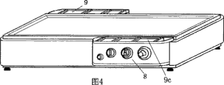
图4为本发明实施例2立体图;Figure 4 is a perspective view of
图5为本发明实施例3立体图;Figure 5 is a perspective view of
图6为本发明实施例4立体透视图;Fig. 6 is a three-dimensional perspective view of
图7为本发明实施例5立体图;Figure 7 is a perspective view of
图8为本发明实施例6立体图;Figure 8 is a perspective view of
图9为本发明升降装置的立体图。Fig. 9 is a perspective view of the lifting device of the present invention.
下面给合附图和实施例对本发明作进一步详述。The present invention will be described in further detail below in conjunction with the accompanying drawings and examples.
结合图1,一种电热炉台,包括台盖1、台面2、台体3、电热器4与4a、温控器5与温控器探棒10、档位器6、定时器7、电控盒8、酱料盒9、电热器支架板或支架条11、隔热防护板12与12a、隔热垫或隔热毡13与13a与13b、台体内腔周侧隔热片或隔热防护板13a与13b、台底封密板14、升降装置(包括电动机15、升降转轴16、升降头17、升降转轴固定座18、升降传动齿轮19、升降电动机固定座20、升降转轴固定座紧固螺丝21、升降电动机固定座20的紧固螺丝22、升降头紧固螺丝23、升降按钮或开关25)、电热器支架板或支架条11的滑槽24与24a、升降电动机隔热罩26、电热器固定片27(图中无显示)、台盖提手31。所述台体分台面2、台身3、电控盒、酱料盒、隔热防护板、台底封密板六部分。With reference to Fig. 1, an electric heating furnace table includes a
所述的台盖1为一活动的盖,用不锈钢或铝制作,台盖1在烹饪食物时可视需要扣盖在台面2凹端沿内,台盖1顶端枢接一提手31;The
所述的台面2扣合在台身3上瑞口外,台面2为一个方凹平面型内空的不锈钢板或铝板或铁板立体罩面,也可以是一个方凹弧面型内空的不锈钢板或铝板或铁板立体罩面,也可以是一个圆凹平面型内空的不锈钢板或铝板或铁板立体罩面,也可以是一个圆凹弧面型内空的不锈钢板或铝板或铁板立体罩面;The
所述的台身3与台面2为一个分体,也可以是一个整体;The
所述的台身3为方型加台底封密板14的不锈钢或铝板或铁板或塑料板空腔立体,也可以是圆型加台底封密板14的不锈钢或铝板或铁板或塑料板空腔圆台体或圆鼓体;Described
所述的台身3的内腔上部与台面内底部接壤处安装电热板或电热管4与4a以及温控器探棒10;Electric heating plates or
所述的台身3正面外侧安装电控盒8,电腔盒8上部为一平面,也可以镶嵌酱料盒;中部内腔中心安装温控器5、档位器6、定时器7、升降按钮或开关25;台身后面外侧外挂酱料盒9,也可以后面、左面、右面外侧同时外挂酱料盒;The
所述的台身3内腔底的台底封密板14上面固定铺垫隔热垫或隔热毡13,周围固定或沾贴隔热片或隔热防护板13a与13b,防止电热板或电热管4与4a的电能热度不必要的损耗及损坏台身以外的物品和器件;The platform
所述的台身3内腔两侧中间竖立安装电热器支架板或支架条11的滑槽24/24a,用来让电热器支架板或支架条11两端在滑槽内上下滑动;The
所述的台底封密板14用不锈钢板或铝板或铁板或铝塑板制作,除了起到密封的作用外,还用以铺垫隔热垫或隔热毡13,以及固定隔热罩26,隔热罩26罩在升降电动机15的外部,用来保护电动机15不被热度损坏;The
所述的升降装置包含电动机15、升降转轴16、升降头17、升降转轴固定座18、升降传动齿轮19、升降电动机固定座20、升降转轴固定座紧固螺丝21、升降电动机固定座20的紧固螺丝22、升降头紧固螺丝孔23。升降转轴16底部固定在升降转轴固定座18内,升降转轴16上部的升降螺齿a旋入升降头17的螺纹(图中未标示)内,升降头17固定在电热器支架板或支架条11底面;The lifting device includes a
所述的电热器支架板或支架条11用不锈钢片或铝片或铁片制作,两端呈T字型嵌入支架滑槽24与24a,支架滑槽24与24a内槽呈平放T型竖立安装在台身3内腔两内侧中;The support plate or
所述的电动机15用电动机支架20经电动机支架紧固螺丝22固定在台底封密板14上面中部位置,其升降传动齿轮19与转动轴转动齿轮b(图中未显示)铰链,由升降按钮或开关25决定电动机15的正、反向转动,电动机15转动带动升降传动齿轮19,升降传动齿轮19带动转动轴转动齿轮b(图中未显示),使升降转轴16转动,升降转轴16转动时经升降转轴16上部的升降螺齿a转动升降头的螺纹(图中未标示)从而实现升降的功能;Described
所述的电热板或电热管4与4a和温控器探棒10由不锈钢片或铝片或铁片用螺丝(图中无显示)固定在电热器支架板或支架条11顶面,电热板或电热管4与4a及温控器探棒10的上面紧贴台面2的内底面,电热板或电热管4与4a经电能作用发热后传感至台面2,使台面2发热而将食物煮熟、蒸热、烤熟、煎熟、炸熟、炖熟、焖熟、炒熟;The electric heating plate or
所述的温控器探棒10探测台面2内底面的温度,当温度高于预设值时,温控器5将电源断开;当温度低于预设值时,温控器5将电源接通,从而起到控制温度和节约电能的作用;The
所述的隔热防护板12与12a用有机玻璃制作,也可用玻璃钢制作,安装在台身3外侧进一步起到安全保护的作用;Described
所述的温控器5为现有技术成熟的产品在此不作详细描述;Described
所述的档位器6有至少一组以上的电桥,为现有技术成熟的产品在此不作详细描述,该档位器6可控制至少一块或一条或一组以上电热板或电热管,档位器6起着对电热板或电热管4与4a供电的控制,当选择电热板或电热管4导电,可将档位器6档级旋钮指向相应的档位。当选择电热板或电热管4a导电时,将档位器6档级旋钮转指向另一相应档位。当选择电热板或电热管4与4a以外更多的电热板或电热管导电时,将档位器6档级旋钮转指向再另一相应档位;The
所述的定时器7,为现有技术成熟的产品在此不作详细描述,它有直通档和时效档的功能,起着对电热板或电热管4与4a直通供电或定时通断电的作用。主要是根据需求控制电热器的有效通电时间;The
所述的电控盒8用不锈钢或塑料制作,主要是用于安装温控器5与档位器6与定时器7与升降按钮和开关。电控盒8用螺丝(图中无显示)紧固在台身3正面侧身,电控盒8与台身3之间有隔热片(图中无显示)隔离,防止台身3感应的热度传至电控盒8而造成损坏温控器5、档位器6、定时器7及升降按钮或开关25;Described
所述的酱料盒9为一盛装食物佐料、佐酱的盒,用不锈钢或塑料制作,安装在台身3后面侧身,酱料盒9与台身3之间有隔热片(图中无显示)隔离,防止台身3感应的热度传至酱料盒9而令调味料或调味酱变热;酱料盒9与台身3之间的隔热片也可取下(图中无显示),便于在冷天时让台身3的热度传至酱料盒9身上,使调味料或调味酱自动加热。Described
所述的隔热垫或隔热毡13、隔热片13a与13b为玻璃纤维材料,目的是有效利用和节约电热能源及防止损坏物品,增强安全性。The heat insulation mat or
实施例1,结合图2与图3,一种电热炉台,包括台盖1、台面2、台体3、电热器4与4a、温控器5与温控器探棒10、档位器6、定时器7、电控盒8,电控盒8的上顶面为一密封的平面、拆卸后的电控盒8的前视图8a、拆卸后的电控盒8的后视图8b、酱料盒9、拆卸后的酱料盒9的前视图9a、拆卸后的酱料盒9的后视图9b、电热器支架板或支架条11、隔热防护板12与12a、隔热垫或隔热毡13、台体内腔周侧隔热片或隔热防护板13a与13b与13c与13d、台底封密板14、升降装置(图中无显示,将在后面单独示意。包括电动机15、升降转轴16、升降头17、升降转轴固定座18、升降传动齿轮19、升降电动机固定座20、升降转轴固定座紧固螺丝21、升降电动机固定座20的紧固螺丝22、升降头紧固螺丝23、)、电热器支架板或支架条11的滑槽24与24a(图中无显示)、升降电动机隔热罩26、电热器固定片27与27a与27b与27c、酱料盒9的挂钉28、电控盒8的电源孔29、电控盒8的固定孔30、台盖提手31、备置换的台面32。所述台体分台面2、台身3、电控盒、酱料盒、隔热防护板、台底封密板六部分。
结合图2与图3,以下描述与图1的描述相同,在此不作细述。所不同的是图2与图3中显示了本发明所述的电热炉台中的台盖1、台面2、台体3、电热板或片4与4a、电控盒8分拆后的前视表示8a及后视表示8b、酱料盒9分拆后的后视表示9a及前视表示9b、电热器支架11与11a、隔热防护板12与12a分拆后的表示12b与12c、隔热垫或毡13、隔热片或隔热防护板13a与13b与13c与13d、备置换的台面32的立体图。With reference to FIG. 2 and FIG. 3 , the following description is the same as that of FIG. 1 , and will not be described in detail here. The difference is that Fig. 2 and Fig. 3 show the front view of the
结合图2与图3,另要说明的是,在图2中显示了两条电热器支架板或支架条11与11a,本发明所述的炉台可安装至少一条以上的电热器支架板或支架条,当安装二条以上电热器支架板或支架条时,需在二条支架板或支架条之中间多横加一条金属连接板,用来在此连接板中间底面固定升降头17。In combination with Fig. 2 and Fig. 3, it should be noted that two electric heater support plates or support bars 11 and 11a are shown in Fig. 2, and at least one electric heater support plate or support can be installed on the furnace platform according to the present invention Bar, when more than two electric heater support plates or support bars are installed, a metal connection plate needs to be added horizontally in the middle of two support plates or support bars, and is used for fixing the lifting
实施例2,结合图4,图4为本发明实施例2立体图,实施例2与实施例1有两处不同,一处不同为实施例2所述的电热器选择的是管状或曲管状电热器;另一处不同为实施例2所述的电控盒8上顶部镶嵌一酱料盒9c。
实施例3,结合图5,图5为本发明实施例3立体图
其中实施例3与实施例1与实施例2不同之处在于:Wherein
(1)实施例3所述的台身3及台面2为正方形;(1)
(2)实施例3所述的台身3及台面2为不可拆卸的整体;(2) The
(3)实施例3所述的炉身四面都有酱料盒9与9a与9b与9c;而且,所述的酱料盒9与9a与9b的高度小于台身3高度;(3) The stove body described in
(4)实施例3中所使用的电热器即可以是实施例1所述的电热板或电热片,也可以是实施例2所述的电热管或曲管;(4) The electric heater used in the
实施例3其余与实施例1与实施例2相同。The rest of
实施例4,结合图6,图6为本发明实施例4立体图
其中实施例4与实施例3不同之处在于:Wherein
(1)实施例4所述的台身3及台面2为可拆卸的分体;(1) the
(2)实施例4所述的电控盒8上端顶面为一密封平面;(2) The top surface of the upper end of the
(3)实施例4备有可置换的凹弧形台面32;(3)
实施例4其余与实施例3相同。The rest of
实施例5,结合图7,图7为本发明实施例5立体透视图。实施例5与实施例3不同之处在于:
(1)实施例5所述的台身3和台面2为一圆形体;(1)
(2)实施例5所述的电控盒8上端顶面为一密封平面,并且电控盒及酱料盒的后面为弧形。(2) The top surface of the upper end of the
(3)实施例5也可在除了电控盒8、酱料盒9这二面之外的左面、右面外挂酱料盒;(3)
实施例5其余与实施例3相同。The rest of
实施例6,结合图8,图8为本发明实施例6的立体图。实施例6与实施例5不同之处在于:
(1)实施例6所述的台身3和台面2为可拆卸的分体;(1) the
(2)实施例6配有可置换的台面32。(2)
实施例6余与实施例5相同。The remainder of
实施例7,结合图9,图9为本发明实施7的立体图。
结合图9,其中实施例7/A与实施例5不同之处在于:In conjunction with Fig. 9, wherein
(1)实施例7/A所述的电控盒8上端顶面镶嵌了酱料盒9c;(1) The top surface of the
实施例7/A其余与实施例5相同。
结合图9,其中实施例7/b与实施例5不同之处在于:In conjunction with Fig. 9, wherein
(1)实施例7/b所述的电控盒8上端顶面镶嵌了酱料盒9c;(1) The top surface of the
(2)实施例7/b所述的台面2为凹圆底形。(2) The
实施例7/b其余与实施例5相同。The rest of
升降装置,结合图10,图10为本发明所述炉台的电热器升降装置的立体图。Lifting device, with reference to Fig. 10, Fig. 10 is a perspective view of the electric heater lifting device of the furnace platform according to the present invention.
图10中,15为电动机、16为升降转轴、17为升降头、18为升降转轴固定座、19为升降传动齿轮、20为升降电动机固定座、21为升降转轴固定座紧固螺丝、22为升降电动机固定座20的紧固螺丝、23a与23b为升降头固定螺孔、a为升降螺齿、b为转动轴转动齿。工作时,升降按钮或开关25控制电动机的正反向转动,电动机15带动升降传动齿轮19,升降传动齿轮19带动升降转轴16下部的转动轴转动齿轮b令升降转轴16转动,升降头17受转动轴上部的升降螺齿a的转动而实现升降的功能。图10所述的升降装置可应用在实施例1、实施例2、实施例3、实施例4、实施例5、实施例6上,在实施例应用中,可安装至少一个以上的升降装置。In Fig. 10, 15 is a motor, 16 is a lifting shaft, 17 is a lifting head, 18 is a lifting shaft fixing seat, 19 is a lifting transmission gear, 20 is a lifting motor fixing seat, 21 is a fastening screw for a lifting shaft fixing seat, and 22 is The fastening screws of the lifting
Claims (10)
Priority Applications (1)
| Application Number | Priority Date | Filing Date | Title |
|---|---|---|---|
| CNB2007100276810A CN100491833C (en) | 2007-04-25 | 2007-04-25 | Electric stove |
Applications Claiming Priority (1)
| Application Number | Priority Date | Filing Date | Title |
|---|---|---|---|
| CNB2007100276810A CN100491833C (en) | 2007-04-25 | 2007-04-25 | Electric stove |
Publications (2)
| Publication Number | Publication Date |
|---|---|
| CN101050871A CN101050871A (en) | 2007-10-10 |
| CN100491833C true CN100491833C (en) | 2009-05-27 |
Family
ID=38782409
Family Applications (1)
| Application Number | Title | Priority Date | Filing Date |
|---|---|---|---|
| CNB2007100276810A Expired - Fee Related CN100491833C (en) | 2007-04-25 | 2007-04-25 | Electric stove |
Country Status (1)
| Country | Link |
|---|---|
| CN (1) | CN100491833C (en) |
Families Citing this family (2)
| Publication number | Priority date | Publication date | Assignee | Title |
|---|---|---|---|---|
| CN106444902A (en) * | 2015-08-05 | 2017-02-22 | 泰奥星(天津)有限公司 | Lubricating oil temperature control device |
| JP6946096B2 (en) * | 2017-07-21 | 2021-10-06 | リンナイ株式会社 | Drop-in stove |
Citations (5)
| Publication number | Priority date | Publication date | Assignee | Title |
|---|---|---|---|---|
| JPS6044731A (en) | 1983-08-19 | 1985-03-09 | Matsushita Electric Ind Co Ltd | Electric heater |
| CN1043194A (en) * | 1988-09-23 | 1990-06-20 | 王文凯 | Household universal electric stove |
| CN2154414Y (en) * | 1993-03-09 | 1994-01-26 | 汪定火 | Temp. adjusting, thermal, electric saving furnace |
| JPH078393A (en) | 1993-06-25 | 1995-01-13 | Tokyo Gas Co Ltd | Lift type temperature sensor device for grill |
| CN2313502Y (en) * | 1997-09-04 | 1999-04-14 | 窦庆德 | Controllable two temperature electric toaster |
-
2007
- 2007-04-25 CN CNB2007100276810A patent/CN100491833C/en not_active Expired - Fee Related
Patent Citations (5)
| Publication number | Priority date | Publication date | Assignee | Title |
|---|---|---|---|---|
| JPS6044731A (en) | 1983-08-19 | 1985-03-09 | Matsushita Electric Ind Co Ltd | Electric heater |
| CN1043194A (en) * | 1988-09-23 | 1990-06-20 | 王文凯 | Household universal electric stove |
| CN2154414Y (en) * | 1993-03-09 | 1994-01-26 | 汪定火 | Temp. adjusting, thermal, electric saving furnace |
| JPH078393A (en) | 1993-06-25 | 1995-01-13 | Tokyo Gas Co Ltd | Lift type temperature sensor device for grill |
| CN2313502Y (en) * | 1997-09-04 | 1999-04-14 | 窦庆德 | Controllable two temperature electric toaster |
Also Published As
| Publication number | Publication date |
|---|---|
| CN101050871A (en) | 2007-10-10 |
Similar Documents
| Publication | Publication Date | Title |
|---|---|---|
| US20070084853A1 (en) | Electric cooking apparatus | |
| CN110973995A (en) | A foldable multifunctional cooking appliance | |
| CN101109526A (en) | induction heating cooker | |
| CN102078138B (en) | Slow saucepan in three-unit pot body structure | |
| CN102172316A (en) | Novel slow cooker of combined structure | |
| CN207520011U (en) | Multifunctional mobile cooking stove | |
| CN103070608A (en) | Three-in-one multi-purpose pot | |
| CN203280256U (en) | Multifunctional heater and pot and disc | |
| CN102133036A (en) | Slow cooker with combination structure of three containers | |
| CN114190786A (en) | A new type of multifunctional electric oven | |
| CN201328691Y (en) | Combination pot with sub-control structure | |
| CN201948764U (en) | Slow stewing pan with combined structure of three pan bodies | |
| CN103349498A (en) | Slow stew pot with computer control panel | |
| CN102133037A (en) | Slow stew-pan with three-unit pan body structure | |
| CN203207794U (en) | Slow-stew pot | |
| CN203369760U (en) | Slow cooker with computer control panel | |
| CN202020287U (en) | Slow stewpan with three-unit pan body structure | |
| CN207784934U (en) | A kind of multifunctional intellectual electric food warmer | |
| CN2759329Y (en) | Electric cooker with multi-steaming layer | |
| CN102197962B (en) | Insulation pot of three-pot-body structure | |
| JPH08312964A (en) | Table cooking appliance | |
| CN201996366U (en) | Heat preservation pot with three-pot body structure | |
| CN101050871A (en) | Electric heating oven table | |
| CN203571812U (en) | Induction cooker | |
| CN211260903U (en) | Take cooking utensils of heating function |
Legal Events
| Date | Code | Title | Description |
|---|---|---|---|
| C06 | Publication | ||
| PB01 | Publication | ||
| C10 | Entry into substantive examination | ||
| SE01 | Entry into force of request for substantive examination | ||
| C14 | Grant of patent or utility model | ||
| GR01 | Patent grant | ||
| C17 | Cessation of patent right | ||
| CF01 | Termination of patent right due to non-payment of annual fee |
Granted publication date: 20090527 Termination date: 20100425 |