CN100484373C - Torsional fixing device for housing of a measuring transducer - Google Patents
Torsional fixing device for housing of a measuring transducer Download PDFInfo
- Publication number
- CN100484373C CN100484373C CN03816756.5A CN03816756A CN100484373C CN 100484373 C CN100484373 C CN 100484373C CN 03816756 A CN03816756 A CN 03816756A CN 100484373 C CN100484373 C CN 100484373C
- Authority
- CN
- China
- Prior art keywords
- groove
- housing
- axial
- sensor
- stop
- Prior art date
- Legal status (The legal status is an assumption and is not a legal conclusion. Google has not performed a legal analysis and makes no representation as to the accuracy of the status listed.)
- Expired - Lifetime
Links
Images


Classifications
-
- G—PHYSICS
- G01—MEASURING; TESTING
- G01F—MEASURING VOLUME, VOLUME FLOW, MASS FLOW OR LIQUID LEVEL; METERING BY VOLUME
- G01F23/00—Indicating or measuring liquid level or level of fluent solid material, e.g. indicating in terms of volume or indicating by means of an alarm
-
- G—PHYSICS
- G01—MEASURING; TESTING
- G01D—MEASURING NOT SPECIALLY ADAPTED FOR A SPECIFIC VARIABLE; ARRANGEMENTS FOR MEASURING TWO OR MORE VARIABLES NOT COVERED IN A SINGLE OTHER SUBCLASS; TARIFF METERING APPARATUS; MEASURING OR TESTING NOT OTHERWISE PROVIDED FOR
- G01D11/00—Component parts of measuring arrangements not specially adapted for a specific variable
- G01D11/24—Housings ; Casings for instruments
-
- Y—GENERAL TAGGING OF NEW TECHNOLOGICAL DEVELOPMENTS; GENERAL TAGGING OF CROSS-SECTIONAL TECHNOLOGIES SPANNING OVER SEVERAL SECTIONS OF THE IPC; TECHNICAL SUBJECTS COVERED BY FORMER USPC CROSS-REFERENCE ART COLLECTIONS [XRACs] AND DIGESTS
- Y10—TECHNICAL SUBJECTS COVERED BY FORMER USPC
- Y10T—TECHNICAL SUBJECTS COVERED BY FORMER US CLASSIFICATION
- Y10T428/00—Stock material or miscellaneous articles
- Y10T428/12—All metal or with adjacent metals
Landscapes
- Physics & Mathematics (AREA)
- General Physics & Mathematics (AREA)
- Fluid Mechanics (AREA)
- Measuring Fluid Pressure (AREA)
- Infusion, Injection, And Reservoir Apparatuses (AREA)
- Transmitters (AREA)
- Clamps And Clips (AREA)
- Measuring Pulse, Heart Rate, Blood Pressure Or Blood Flow (AREA)
Abstract
Description
技术领域 technical field
本发明涉及扭转固定零件,其可以用于例如测量变送器的电子仪器的外壳。The invention relates to a torsionally fixed part which can be used in the housing of an electronic instrument such as a measuring transducer.
背景技术 Background technique
这种外壳通常体现为两部分,外壳的第一部分可通过预定的角范围相对于第二部分扭转,以将第一外壳部分上排列的例如显示或操作元件旋转入期望的方位。由于电缆通常在第一和第二外壳部分之间延伸,所以必须限定角范围,以防止与其相连的电缆或部件的损坏。Such housings are usually embodied in two parts, the first part of the housing being twistable relative to the second part through a predetermined angular range in order to rotate eg display or operating elements arranged on the first housing part into a desired orientation. Since the cables usually extend between the first and second housing parts, the angular extent must be limited to prevent damage to the cables or components connected thereto.
受让人的差压变送器名为“Deltabar”,其具有以下所述的扭转固定零件。第一外壳部分具有管状的第一连接法兰,该第一连接法兰带有内螺纹,该内螺纹旋至第二外壳部分的互补的第二连接法兰的外螺纹。止动销从第二连接法兰的圆柱形圆周表面,在与第一连接法兰轴向分离的部分中径向向外延伸。在第一连接法兰旋至第二连接法兰之后,金属舌被安装在第一连接法兰的圆周表面上。金属舌在轴向上延伸跨过第一连接法兰并且在轴向上重叠止动销。结果,第二连接法兰相对于第一连接法兰的扭转在两个方向上都由金属舌在止动销上的撞击而限定。Assignee's differential pressure transmitter, named "Deltabar", has the torsionally fixed parts described below. The first housing part has a tubular first connecting flange with an internal thread which is screwed to the external thread of a complementary second connecting flange of the second housing part. The stop pin extends radially outward from the cylindrical peripheral surface of the second connecting flange in a portion axially separated from the first connecting flange. After the first connecting flange is screwed to the second connecting flange, the metal tongue is mounted on the circumferential surface of the first connecting flange. A metal tongue extends axially across the first connecting flange and axially overlaps the stop pin. As a result, the twisting of the second connecting flange relative to the first connecting flange is limited in both directions by the impact of the metal tongue on the stop pin.
尽管这样描述的扭转固定零件是可靠的,但是还需要考虑它的制造和安装。Although the torsionally fixed part thus described is reliable, its manufacture and installation also need to be considered.
所述的问题不仅涉及压力传感器,而且非常通常的,还涉及工业过程测量技术的所有传感器,尤其是流速传感器、粘度传感器、料位传感器、pH传感器和其它电位传感器、温度传感器、湿度传感器、气体传感器和浊度传感器。The problem described concerns not only pressure sensors but, very generally, all sensors of industrial process measurement technology, especially flow rate sensors, viscosity sensors, level sensors, pH sensors and other potentiometric sensors, temperature sensors, humidity sensors, gas sensors and turbidity sensors.
发明内容 Contents of the invention
因此,本发明的目的是提供一种用于将设备的部件,特别是外壳部件,旋接在一起的扭转固定零件或扭转挡板零件。It is therefore an object of the present invention to provide a torsion-fixing part or a torsion-stop part for screwing together parts of a device, in particular housing parts.
本发明公开了一种用于电子设备的外壳元件的扭转固定零件,其中外壳元件具有在其外表面上形成的第一螺纹,并且该电子设备还包括第二元件,该第二元件具有在其内表面上形成的第二螺纹,该第二螺纹与第一螺纹互补并通过将第二元件旋入外壳元件而与第一螺纹啮合。外壳元件和第二元件可以围绕两条螺纹的轴相对于彼此扭转,并且扭转导致它们的相对轴向位置由于螺距而改变。扭转固定零件将外壳元件相对于第二元件的扭转限定在一个角范围。扭转固定零件包括止动环,其与径向向外延伸的第一槽和径向向内延伸的第二槽啮合,其中第一槽位于外壳元件中的圆柱形开口的圆周表面中,并且第二槽位于第二元件中的圆柱形部分的圆周表面中,圆柱形部分这样位于圆柱形开口中,使得第一槽与第二槽在轴向上至少部分重叠;其中止动环的上端面和下端面以及约束第一和第二槽的径向级共同限定两个轴向止块,其中当止动环的上端面毗邻第一槽的上径向级且止动环的下端面毗邻第二槽的下径向级时达到第一止块,当止动环的上端面毗邻第二槽的上径向级且止动环的下端面毗邻第一槽的下径向级时达到第二止块,从而外壳元件相对于第二元件的轴向位置被限制在由轴向止块确定的两个极限位置之间的范围。The invention discloses a twist fixing part for a casing element of an electronic device, wherein the casing element has a first thread formed on its outer surface, and the electronic device further comprises a second element having a screw thread formed on its outer surface. A second thread is formed on the inner surface, the second thread is complementary to the first thread and is engaged with the first thread by screwing the second member into the housing member. The housing element and the second element can be twisted relative to each other about the axes of the two threads, and the twisting causes their relative axial positions to change due to the pitch of the threads. The torsional securing feature limits the torsion of the housing element relative to the second element to an angular range. The torsional fixation part includes a snap ring engaging a radially outwardly extending first groove and a radially inwardly extending second groove, wherein the first groove is located in the circumferential surface of the cylindrical opening in the housing element, and the second groove extends radially inwardly. Two grooves are located in the circumferential surface of the cylindrical portion in the second element, the cylindrical portion being located in the cylindrical opening such that the first groove and the second groove overlap at least partially in the axial direction; wherein the upper end surface of the stop ring and The lower end face and the radial stages bounding the first and second grooves together define two axial stops, wherein when the upper end face of the snap ring adjoins the upper radial stage of the first groove and the lower end face of the snap ring adjoins the second The first stop is reached when the lower radial level of the groove is reached, and the second stop is reached when the upper end face of the snap ring is adjacent to the upper radial level of the second groove and the lower end face of the snap ring is adjacent to the lower radial level of the first groove. block, so that the axial position of the housing element relative to the second element is limited to a range between two extreme positions determined by the axial stop.
根据本发明还公开了另一种用于电子设备的外壳元件的扭转固定零件,其中外壳元件具有第一螺纹,并且该电子设备还包括第二元件,其具有与第一螺纹互补并与其啮合的第二螺纹。其中外壳元件和第二元件可以围绕两条螺纹的轴相对于彼此扭转,并且扭转导致它们的相对轴向位置由于螺纹的螺距而改变。扭转固定零件将外壳元件相对于第二元件的可扭转性限定在一个角范围。扭转固定零件包括:环形槽,其位于第二元件的圆柱形部分并且径向向内延伸,其中环形槽在轴向上由第一和第二径向级限定;和销或突起,其与不具有槽的元件固定连接并且径向向内或径向向外突出入槽中;第一和第二径向级分别用作对于销或突起的轴向止动面,其中与槽啮合的销或突起限定两个轴向止块,使得外壳元件相对于第二元件的轴向位置被限制在由轴向止块确定的两个极限位置之间的范围。According to the present invention there is also disclosed another twist-fixed part for a casing element of an electronic device, wherein the casing element has a first thread, and the electronic device further comprises a second element having a thread complementary to and engaged with the first thread second thread. Wherein the housing element and the second element can be twisted relative to each other about the axis of the two threads, and the twisting causes their relative axial position to change due to the pitch of the threads. The torsionally fastening element limits the twistability of the housing element relative to the second element to an angular range. The torsionally fixed part comprises: an annular groove located in the cylindrical portion of the second member and extending radially inwardly, wherein the annular groove is axially delimited by the first and second radial stages; The element with the groove is fixedly connected and protrudes radially inwards or radially outwards into the groove; the first and second radial stages act respectively as axial stop surfaces for the pin or the protrusion, wherein the pin or the protrusion engaging the groove The protrusion defines two axial stops such that the axial position of the housing element relative to the second element is limited to a range between two extreme positions determined by the axial stops.
优选的,还这样设置轴向止块,使得极限位置之间的差等于在给定螺距的情况下,将外壳元件相对于第二元件扭转最大允许扭转角而引起的轴向偏移。Preferably, the axial stop is also arranged such that the difference between the extreme positions is equal to the axial deflection caused by twisting the housing element relative to the second element by the maximum allowable twist angle for a given thread pitch.
轴向止块优选地在元件,即外壳元件或第二元件,的至少一个上具有优选为旋转对称的轴向止动面,其用作止动或耦合元件的止动,以这样的方式将与其它元件耦合,使得止动元件相对于其它元件的运动自由度至少在轴向上受到限制。运动自由度的限制可以类似地由其它元件上的轴向止动面保证,或者止动元件可以固定地与其它元件相连。The axial stop preferably has a preferably rotationally symmetrical axial stop surface on at least one of the elements, ie the housing element or the second element, which serves as a stop or a stop for the coupling element, in such a way that the Coupling with the other element is such that the freedom of movement of the stop element relative to the other element is restricted at least axially. The limitation of the freedom of movement can similarly be ensured by axial stop surfaces on the other element, or the stop element can be fixedly connected to the other element.
特别地,轴向止动面可以由两个同轴圆柱形部分之间的轴向级形成。为此,外壳元件的圆周表面,或者第二元件的圆周表面,可以具有这种圆柱形部分。特别地,外壳元件或第二元件的圆柱形部分的圆周表面可以具有环形槽,其径向向内延伸,并且在轴向方向上由第一和第二径向级限定,其中第一和第二径向级各自用作两个轴向止块之一的轴向止动面。In particular, the axial stop surface can be formed by an axial step between two coaxial cylindrical parts. For this purpose, the peripheral surface of the housing element, or the peripheral surface of the second element, may have such a cylindrical portion. In particular, the circumferential surface of the cylindrical part of the housing element or the second element may have an annular groove extending radially inwards and defined in the axial direction by first and second radial stages, wherein the first and second The two radial stages each serve as an axial stop surface for one of the two axial stops.
类似地,外壳元件或第二元件可以包括至少一个具有不同半径的圆柱形部分的开口,其旋转轴与螺纹的轴对齐,在不同半径的至少两个部分之间形成径向级,其用作扭转固定零件的轴向止块的轴向止动面。特别地,可以在外壳元件或第二元件的圆柱形开口的圆周表面中提供环形槽,其径向向外延伸并且在轴向方向上由第一和第二径向级约束,第一和第二径向级各自用作两个轴向止块之一的轴向止动面。Similarly, the housing element or the second element may comprise at least one opening with cylindrical sections of different radii, the axis of rotation of which is aligned with the axis of the thread, forming a radial step between at least two sections of different radii, which serve as Twist the axial stop face of the axial stop of the fixed part. In particular, an annular groove may be provided in the circumferential surface of the cylindrical opening of the housing element or the second element, which extends radially outwards and is constrained in the axial direction by first and second radial stages, the first and second The two radial stages each serve as an axial stop surface for one of the two axial stops.
为了用作止动部件,可以提供销或突起,其固定地与其它元件,即不具有槽的元件,相连并且径向向内或径向向外突出入槽中。For use as a stop member, pins or projections can be provided which are fixedly connected to the other element, ie the element which does not have a groove, and protrude radially inwards or radially outwards into the groove.
当前特别优选的是以下实施例形式,其中止动环与第一径向向外延伸的槽以及第二径向向内延伸的槽啮合,其中第一槽位于外壳元件或第二元件中圆柱形开口的圆周表面中,并且其它元件具有圆柱形部分,第二槽位于该圆柱形部分的圆周表面中,圆柱形部分以这样的方式位于圆柱形开口之中,使得第一槽在轴向上至少部分重叠第二槽。Presently particularly preferred is an embodiment form in which the snap ring engages a first radially outwardly extending groove and a second radially inwardly extending groove, wherein the first groove is located in either the housing element or the second element. In the circumferential surface of the opening, and the other element has a cylindrical portion, the second groove is located in the circumferential surface of the cylindrical portion, the cylindrical portion is located in the cylindrical opening in such a way that the first groove is axially at least Partially overlaps the second slot.
在特别优选的实施例形式中,止动环是弹簧环或者径向可弯曲的环形垫圈。In a particularly preferred embodiment form, the retaining ring is a spring ring or a radially bendable annular washer.
优选地,止动环包括比其中形成槽的材料更软的材料。例如,外壳元件和第二元件可以至少部分地由金属,特别是钢、铸铁或铝制成,而止动环优选地由合成材料,特别是人造橡胶或热塑材料制成。Preferably, the snap ring comprises a softer material than the material in which the groove is formed. For example, the housing element and the second element can be at least partially made of metal, in particular steel, cast iron or aluminium, while the snap ring is preferably made of synthetic material, in particular elastomer or thermoplastic material.
在当前优选的实施例形式中,外壳元件与第二元件之间在插入止动环的情况下的旋接是不可逆的,使得如果不破坏止动环就不可能解除该旋接。于是,止动环可以起到密封的作用,它的完整性可以例如是保证性能的首要条件。In a presently preferred embodiment form, the screw connection between the housing element and the second element with the insertion of the snap ring is irreversible, so that it is not possible to unscrew the screw connection without destroying the snap ring. The snap ring may then act as a seal, the integrity of which may eg be a prerequisite for performance.
止动环的轴向尺寸,即特别是其材料厚度,优选地这样匹配第一和第二槽的宽度,使得第一和第二槽的宽度之和减去轴向尺寸的二倍等于在给定的螺距处外壳元件相对于第二元件旋转最大允许扭转角而得到的轴向偏移。The axial dimension of the snap ring, in particular its material thickness, is preferably adapted to the widths of the first and second grooves such that the sum of the widths of the first and second grooves minus twice the axial dimension is equal to the given The axial deflection obtained by rotating the housing element relative to the second element at the maximum allowable torsion angle at a given pitch.
最大扭转角不应大于720°,即两整圈。在当前优选的实施例形式中,最大扭转角为360°。这样,外壳元件和第二元件可以相对彼此呈现任何定位。这对于外壳元件具有对于操作者适宜地定位的显示域和/或操作元件的实施例形式,特别重要。The maximum twist angle should not be greater than 720°, that is, two full turns. In a presently preferred embodiment form, the maximum twist angle is 360°. In this way, the housing element and the second element may assume any orientation relative to each other. This is particularly important for embodiments in which the housing element has display fields and/or operating elements that are positioned suitably for the operator.
为了应用于过程测量技术,外壳元件优选地包括测量变送器外壳,其具有第二元件,该第二元件优选地具有连接适配器或传感器外壳,用于连接至测量变送器外壳。For use in process measurement technology, the housing element preferably comprises a measuring transmitter housing which has a second element which preferably has a connection adapter or sensor housing for connection to the measuring transmitter housing.
附图说明 Description of drawings
现在根据附图中所示的实施例详细解释本发明,附图中:Now explain the present invention in detail according to the embodiment shown in the accompanying drawing, in the accompanying drawing:
图1是本发明的设备的透视图,该设备包括测量变送器和传感器;Fig. 1 is the perspective view of the device of the present invention, this device comprises measuring transducer and sensor;
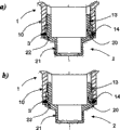
图2是本发明的设备的纵向详细视图,显示了测量变送器外壳和传感器外壳之间的连接;和Figure 2 is a longitudinal detailed view of the device of the present invention showing the connection between the measuring transmitter housing and the sensor housing; and
图3是本发明的设备的止动环。Figure 3 is a stop ring of the device of the present invention.
具体实施方式 Detailed ways
图1所示的测量变送器外壳1具有鼓状外壳部分11,其中通常放置电子部件,特别是用于数据通信的部件。在鼓状外壳部分11的圆周表面中提供开口,其由基本为管状的连接法兰10定义,传感器元件2旋入该连接法兰10。因为本发明并不关注传感器元件2的内部结构,这个传感器元件2在图1中以实线框描绘。传感器元件2具有至少部分圆柱形的变送器连接20,其旋入管状连接法兰10的开口中。为此,在变送器连接20的圆周表面上提供螺纹部分,其与连接法兰10的内壁上的互补内螺纹13啮合。在这个实施例中,传感器元件2还具有圆柱形过程连接插头21,其圆周表面具有螺纹,传感器元件可以通过该螺纹固定至例如管道中合适的容器或开口。对于本领域技术人员,很明显要提供合适的密封,但是本发明不必对此细述。The measuring transmitter housing 1 shown in FIG. 1 has a drum-
测量变送器外壳1在鼓状外壳部分11的一个端面上具有显示域12。为了能够将该显示域转向任意定位,测量变送器外壳必须可以相对于传感器元件2扭转。然而,例如为了避免损坏从传感器元件2延伸入变送器外壳1的电缆,可扭转性限于较小的角范围。这由本发明的扭转固定零件保证,其使用两个轴向止块将变送器外壳1相对于传感器元件2的轴向位置限定至当变送器外壳1围绕螺纹轴旋转最大允许旋转角时基于内螺纹13的螺距所覆盖的范围。The measuring transmitter housing 1 has a
图2显示了变送器外壳1的鼓状连接法兰10的两个纵向视图,传感器元件2的变送器连接20已经旋入该法兰10。每一视图显示了不同轴位置中的变送器连接20。FIG. 2 shows two longitudinal views of the drum-shaped connecting
管状连接法兰10在其内壁中具有径向向外延伸的第一环形槽14。第一环形槽14由两个径向级约束,这两个径向级相互之间的轴向分离定义了第一环形槽14的宽度B1。以相似的方式,变送器连接20在其圆周表面上具有环形槽22,其径向向内延伸。第二环形槽22类似地由两个径向级约束,这两个径向级相互之间的轴向分离定义了第二环形槽22的第二宽度B2。The
限定第一和第二环形槽的径向级用作止动环3的轴向止动面。止动环3是环形垫圈并且是径向可弯曲的。止动环3与第一环形槽14和第二环形槽22都啮合,即,止动环3的外半径Ro大于连接法兰10在第一环形槽14径向向外延伸的部分中的内壁的半径,并且止动环3的内半径Ri小于连接法兰20在第二环形槽22径向向内延伸的部分中的圆周表面的半径。The radial stages delimiting the first and second annular grooves serve as axial stop surfaces for the
止动环3具有上端面30和下端面31,它们优选地至少部分地相互平行。端面30、31和轴向止动面一起形成轴向止块,用于限制变送器外壳1相对于传感器元件2的运动。下面描述轴向止块的效果。这里的概念“上”或“下”是指朝向或远离过程连接的方向。The retaining
图2的a)部分显示了变送器外壳1已经达到相对于传感器元件2的下极限位置的情况。在这个情况中,下端面31的内部区域碰撞毗邻第二环形槽22的下轴向止动面,并且上端面30的外部区域碰撞毗邻第一环形槽14的上轴向止动面。Part a) of FIG. 2 shows the situation where the transmitter housing 1 has reached the lower limit position relative to the
图2的b)部分显示了变送器外壳1已经达到相对于传感器元件2的上极限位置的情况。在这个情况中,下端面31的外部区域碰撞毗邻第一环形槽14的下轴向止动面,并且上端面30的内部区域碰撞毗邻第二环形槽22的上轴向止动面。Part b) of FIG. 2 shows the situation where the transmitter housing 1 has reached the upper limit position relative to the
止动环3在第一环形槽的区域中具有第一轴向厚度T1,并且在第二环形槽的区域中具有第二轴向厚度T2。在当前的优选实施例形式中,第一轴向厚度T1等于第二轴向厚度T2(T1=T2=T)。然而,原理上,它们可以不相同。止动环的第一轴向厚度T1和第二轴向厚度T2以及第一环形槽的第一宽度B1和第二环形槽的第二宽度B2相互之间保持以下关系:The
(B1-T1)+(B2-T2)=S(φmax),(B 1 -T 1 )+(B 2 -T 2 )=S(φ max ),
其中S(φmax)是螺纹13在变送器外壳1扭转最大扭转角φmax时的轴向偏移。对于T1=T2=T,Wherein S(φ max ) is the axial offset of the
B1+B2-2T=S(φmax)。B 1 +B 2 -2T=S(φ max ).
在当前优选实施例形式中,最大扭转角φmax约为360°。在这种情况中,变送器外壳1可以采取相对于传感器元件2的任一可能定位,并且在传感器元件2和变送器外壳1之间延伸的连接电缆最多一次旋转。In a presently preferred embodiment form, the maximum twist angle φ max is approximately 360°. In this case, the transmitter housing 1 can assume any possible positioning relative to the
图3所示的止动环3在其上端面30的外边缘上具有倾斜面34。另外,环被狭缝33打断,以便于在传感器元件2上安装变送器外壳1。这个实施例形式的止动环优选地由弹性材料制成。为了安装,首先将弹性止动环3安装在第二环形槽22中。然后,将变送器外壳1旋至传感器元件2上,令止动环3由连接法兰10的内壁完全压入第二环形槽22,直至第一环形槽14充分重叠第二环形槽22,使得止动环3可以回弹并啮合第一环形槽14,从而完成扭转固定零件。The retaining
图3中所示的突起35是可选零件,用于固定止动环相对于变送器外壳1的旋转。然而,这个零件对于本发明不是关键的。在包含这个零件的实施例形式中,在连接法兰10的内壁中提供轴向上的槽,用于以足够的轴向间隙容纳突起。The
另一实施例形式与上面所述的不同在于,没有提供止动环和第一槽。代替它们的是,至少一个止动体,例如止动销,固定连接至连接法兰20并且延伸入第二环形槽。在这个情况中,止动体的第二宽度和轴向尺寸之间的差确定了在变送器主体扭转最大角的情况中的螺纹偏移。A further embodiment form differs from that described above in that the snap ring and the first groove are not provided. Instead, at least one stop body, for example a stop pin, is fixedly connected to the
止动销可以例如以螺栓的形式提供,连接法兰10的圆周表面中的径向穿越的螺孔重叠第二环形槽时,其旋入该螺孔。可选的,可以提供紧固螺丝,其固定变送器外壳相对于传感器元件的优选定位。用于接收紧固螺丝的径向螺孔可以特别地以通过止动销的同轴螺孔的形式提供。The stop pin can be provided, for example, in the form of a bolt into which a radially passing threaded hole in the peripheral surface of the connecting
Claims (8)
Applications Claiming Priority (2)
| Application Number | Priority Date | Filing Date | Title |
|---|---|---|---|
| DE10232088A DE10232088A1 (en) | 2002-07-15 | 2002-07-15 | Protection against rotation, in particular for a transmitter housing |
| DE10232088.8 | 2002-07-15 |
Publications (2)
| Publication Number | Publication Date |
|---|---|
| CN1669375A CN1669375A (en) | 2005-09-14 |
| CN100484373C true CN100484373C (en) | 2009-04-29 |
Family
ID=30010023
Family Applications (1)
| Application Number | Title | Priority Date | Filing Date |
|---|---|---|---|
| CN03816756.5A Expired - Lifetime CN100484373C (en) | 2002-07-15 | 2003-07-14 | Torsional fixing device for housing of a measuring transducer |
Country Status (8)
| Country | Link |
|---|---|
| US (1) | US7426870B2 (en) |
| EP (1) | EP1527660B1 (en) |
| CN (1) | CN100484373C (en) |
| AT (1) | ATE429801T1 (en) |
| AU (1) | AU2003246695A1 (en) |
| DE (2) | DE10232088A1 (en) |
| RU (1) | RU2289894C2 (en) |
| WO (1) | WO2004008820A1 (en) |
Cited By (1)
| Publication number | Priority date | Publication date | Assignee | Title |
|---|---|---|---|---|
| CN109937347A (en) * | 2017-08-29 | 2019-06-25 | 罗斯蒙特公司 | Process transmitter with rotatable connector |
Families Citing this family (16)
| Publication number | Priority date | Publication date | Assignee | Title |
|---|---|---|---|---|
| DE102008001865A1 (en) | 2008-05-19 | 2009-11-26 | Endress + Hauser Gmbh + Co. Kg | gauge |
| US9329061B2 (en) * | 2013-02-28 | 2016-05-03 | Rosemount Inc. | Reduced-stress coupling for industrial process transmitter housing |
| ITUD20130086A1 (en) * | 2013-06-20 | 2014-12-21 | Eliwell Controls S R L Con Unico S Ocio | ELECTRONIC MEASUREMENT, CONDITIONING AND ADJUSTMENT INSTRUMENT AND ITS PANEL MOUNTING PROCEDURE |
| DE102013216524B3 (en) * | 2013-08-21 | 2014-10-02 | Ifm Electronic Gmbh | Pressure transmitter with rotatable housing sleeve |
| DE102014116674A1 (en) * | 2014-11-14 | 2016-05-19 | Endress + Hauser Gmbh + Co. Kg | Field device of automation technology |
| RU2594380C1 (en) * | 2015-06-23 | 2016-08-20 | Общество с ограниченной ответственностью "Приборы автоцистерн" | Transport level sensor design (versions) and set of equipment for fluid parameter control system (versions) |
| JP6612134B2 (en) * | 2016-01-08 | 2019-11-27 | 株式会社ノーケン | Enclosure with illuminant and level detection apparatus having the same |
| GB2592865B (en) * | 2019-10-24 | 2022-06-15 | Caterpillar Global Mining Europe Gmbh | Human interface operating device of an underground mining machine |
| CN110905483B (en) * | 2019-11-07 | 2023-03-21 | 西安康际石油科技有限公司 | Integrated flowmeter for microwave water content and flow of oil field |
| US11725966B2 (en) * | 2020-09-18 | 2023-08-15 | Rosemount Inc. | Multi-stage irreversible sensor coupling |
| KR20230130087A (en) * | 2021-01-12 | 2023-09-11 | 마이크로 모우션, 인코포레이티드 | Interface with improved accessibility |
| DE102021117316A1 (en) * | 2021-07-05 | 2023-01-05 | BEDIA Motorentechnik GmbH & Co. KG | Sensor device for detecting sensor information describing the fill level of a medium in a container |
| CN113639833B (en) * | 2021-08-13 | 2024-07-12 | 麦克传感器股份有限公司 | Liquid level transmitter testing device and method based on pneumatic control |
| CN114136254B (en) * | 2021-11-01 | 2024-04-09 | 庆安集团有限公司 | Anti-torsion structure of external linear displacement sensor with rotatable actuator piston rod |
| DE102024105813B4 (en) * | 2024-02-29 | 2025-12-04 | Sennheiser Electronic Se & Co. Kg | microphone holder |
| DE102024129624B3 (en) * | 2024-10-14 | 2025-10-30 | Sick Ag | Connection device |
Family Cites Families (18)
| Publication number | Priority date | Publication date | Assignee | Title |
|---|---|---|---|---|
| GB1208725A (en) * | 1966-11-08 | 1970-10-14 | Plessey Co Ltd | Improvements in or relating to spindle stop arrangements |
| DE2439662C3 (en) * | 1974-08-19 | 1978-10-12 | Graenges Oxeloesunds Jaernverk Ab, Oxeloesund (Schweden) | Device for the non-destructive testing of metallic blanks for surface defects |
| CH657433A5 (en) * | 1981-09-14 | 1986-08-29 | Sig Schweiz Industrieges | DEVICE FOR LIMITING THE TURNING ANGLE IN SCREW GEAR AND FLUIDIC CONTROL DEVICE. |
| DE3211238A1 (en) * | 1982-03-26 | 1983-10-06 | Wolf Woco & Co Franz J | TURN-ELASTIC CLUTCH |
| CH666765A5 (en) * | 1985-02-08 | 1988-08-15 | Sprecher & Schuh Ag | OPERATING DEVICE FOR A SWITCH WITH A ROTATABLE HANDLE. |
| GB8719298D0 (en) * | 1987-08-14 | 1987-09-23 | Lucas Ind Plc | Coupling |
| DE3742647A1 (en) * | 1987-12-16 | 1989-06-29 | Mannesmann Kienzle Gmbh | ARRANGEMENT FOR FIXING A HOUSING |
| DE3828589A1 (en) * | 1988-08-23 | 1990-03-08 | Le Instrumentalnyj Z | Measuring screw of a transmitter having linear displacement |
| US5088339A (en) * | 1990-11-30 | 1992-02-18 | Roton Products, Inc. | Limit stop assembly for a screw and nut linear actuator |
| FR2686130B1 (en) * | 1992-01-10 | 1994-11-10 | Nacam | FIXING DEVICE WITH A RETRACTABLE AXIAL GUIDE STOP. |
| DE4213857C2 (en) * | 1992-04-27 | 1995-10-19 | Endress Hauser Gmbh Co | Device for measuring pressure and differential pressure |
| CH686245A5 (en) * | 1992-05-04 | 1996-02-15 | Createchnic Ag | Central sealing plug. |
| DE4244459C1 (en) * | 1992-12-23 | 1994-05-11 | Siemens Ag | Pressure transmitter |
| DE59509388D1 (en) * | 1995-09-28 | 2001-08-09 | Endress Hauser Gmbh Co | Ultrasonic transducer |
| GB2315167B (en) * | 1996-07-08 | 1999-04-21 | Amphenol Corp | Electrical connector and cable termination system |
| US5810828A (en) * | 1997-02-13 | 1998-09-22 | Mednext, Inc. | Adjustable depth drill guide |
| DE19948168C1 (en) * | 1999-10-07 | 2001-01-11 | Repac Petra | Garlic press has rotatable housing upper part with press element used to press garlic through blade mesh via axial displacement upon selective engagement of screw thread provided by housing body |
| US6557431B2 (en) * | 2001-02-02 | 2003-05-06 | Siemens Medical Solutions Usa, Inc. | Fail-safe ball screw |
-
2002
- 2002-07-15 DE DE10232088A patent/DE10232088A1/en not_active Withdrawn
-
2003
- 2003-07-14 AU AU2003246695A patent/AU2003246695A1/en not_active Abandoned
- 2003-07-14 US US10/521,459 patent/US7426870B2/en not_active Expired - Lifetime
- 2003-07-14 WO PCT/EP2003/007616 patent/WO2004008820A1/en not_active Ceased
- 2003-07-14 AT AT03763849T patent/ATE429801T1/en not_active IP Right Cessation
- 2003-07-14 EP EP03763849A patent/EP1527660B1/en not_active Expired - Lifetime
- 2003-07-14 CN CN03816756.5A patent/CN100484373C/en not_active Expired - Lifetime
- 2003-07-14 DE DE50311453T patent/DE50311453D1/en not_active Expired - Lifetime
- 2003-07-14 RU RU2005103837/09A patent/RU2289894C2/en active
Cited By (3)
| Publication number | Priority date | Publication date | Assignee | Title |
|---|---|---|---|---|
| CN109937347A (en) * | 2017-08-29 | 2019-06-25 | 罗斯蒙特公司 | Process transmitter with rotatable connector |
| CN109937347B (en) * | 2017-08-29 | 2021-12-07 | 罗斯蒙特公司 | Process transmitter with rotatable coupling |
| US11248936B2 (en) | 2017-08-29 | 2022-02-15 | Rosemount Inc. | Process transmitter having a rotatable coupling |
Also Published As
| Publication number | Publication date |
|---|---|
| WO2004008820A1 (en) | 2004-01-22 |
| DE50311453D1 (en) | 2009-06-04 |
| DE10232088A1 (en) | 2004-02-05 |
| US20060121301A1 (en) | 2006-06-08 |
| EP1527660A1 (en) | 2005-05-04 |
| RU2289894C2 (en) | 2006-12-20 |
| ATE429801T1 (en) | 2009-05-15 |
| EP1527660B1 (en) | 2009-04-22 |
| CN1669375A (en) | 2005-09-14 |
| US7426870B2 (en) | 2008-09-23 |
| RU2005103837A (en) | 2006-01-20 |
| AU2003246695A1 (en) | 2004-02-02 |
Similar Documents
| Publication | Publication Date | Title |
|---|---|---|
| CN100484373C (en) | Torsional fixing device for housing of a measuring transducer | |
| RU2444737C2 (en) | Pulse sensor with seal device | |
| CN100491800C (en) | Middle ring of adaptor for screwing unit for fluid pipeline quick inserting system | |
| US4950085A (en) | Multi-positional thermometer | |
| US6045261A (en) | Temperature sensor assembly | |
| EP1394552B1 (en) | Method and apparatus for avoiding internal air gaps in magnetic sensor housings | |
| CN111742155A (en) | Ball Joints and Dust Covers | |
| CN101874327B (en) | Connecting flange, particularly for an electric terminal | |
| JP2020172954A (en) | Dust-proof cap, attachment structure of the same, and attachment method of the same | |
| KR20100045368A (en) | Tube fitting | |
| CN109723823B (en) | Device with sealing mechanism | |
| CN214099889U (en) | Radar Level Gauge | |
| JPH0450488Y2 (en) | ||
| US5144837A (en) | Acceleration detector | |
| CN223807945U (en) | Radar level gauge shell structure | |
| JP2762415B2 (en) | Position detector cable connection structure | |
| GB2153943A (en) | Compression pipe fitting | |
| KR100630544B1 (en) | Pipe joint | |
| CN223294080U (en) | Anti-loosening locking device | |
| CN112823458A (en) | Cable connector | |
| US20240128660A1 (en) | Ground connection terminal | |
| US20180230757A1 (en) | Set Screw Anti-Rotation Device with Knurl Surface | |
| JP2005291283A (en) | Housing type pipe fitting | |
| CN112821036A (en) | Radar level meter | |
| KR20000035621A (en) | Spindle bearing arrangement |
Legal Events
| Date | Code | Title | Description |
|---|---|---|---|
| C06 | Publication | ||
| PB01 | Publication | ||
| C10 | Entry into substantive examination | ||
| SE01 | Entry into force of request for substantive examination | ||
| C14 | Grant of patent or utility model | ||
| GR01 | Patent grant | ||
| CX01 | Expiry of patent term |
Granted publication date: 20090429 |
|
| CX01 | Expiry of patent term |