CN100481671C - Battery charger - Google Patents
Battery charger Download PDFInfo
- Publication number
- CN100481671C CN100481671C CNB2005100792232A CN200510079223A CN100481671C CN 100481671 C CN100481671 C CN 100481671C CN B2005100792232 A CNB2005100792232 A CN B2005100792232A CN 200510079223 A CN200510079223 A CN 200510079223A CN 100481671 C CN100481671 C CN 100481671C
- Authority
- CN
- China
- Prior art keywords
- power supply
- voltage
- supply circuits
- secondary cell
- splicing ear
- Prior art date
- Legal status (The legal status is an assumption and is not a legal conclusion. Google has not performed a legal analysis and makes no representation as to the accuracy of the status listed.)
- Expired - Fee Related
Links
Images

Classifications
-
- H—ELECTRICITY
- H02—GENERATION; CONVERSION OR DISTRIBUTION OF ELECTRIC POWER
- H02J—CIRCUIT ARRANGEMENTS OR SYSTEMS FOR SUPPLYING OR DISTRIBUTING ELECTRIC POWER; SYSTEMS FOR STORING ELECTRIC ENERGY
- H02J7/00—Circuit arrangements for charging or depolarising batteries or for supplying loads from batteries
- H02J7/02—Circuit arrangements for charging or depolarising batteries or for supplying loads from batteries for charging batteries from ac mains by converters
-
- H—ELECTRICITY
- H02—GENERATION; CONVERSION OR DISTRIBUTION OF ELECTRIC POWER
- H02J—CIRCUIT ARRANGEMENTS OR SYSTEMS FOR SUPPLYING OR DISTRIBUTING ELECTRIC POWER; SYSTEMS FOR STORING ELECTRIC ENERGY
- H02J9/00—Circuit arrangements for emergency or stand-by power supply, e.g. for emergency lighting
- H02J9/005—Circuit arrangements for emergency or stand-by power supply, e.g. for emergency lighting using a power saving mode
-
- H—ELECTRICITY
- H02—GENERATION; CONVERSION OR DISTRIBUTION OF ELECTRIC POWER
- H02J—CIRCUIT ARRANGEMENTS OR SYSTEMS FOR SUPPLYING OR DISTRIBUTING ELECTRIC POWER; SYSTEMS FOR STORING ELECTRIC ENERGY
- H02J2207/00—Indexing scheme relating to details of circuit arrangements for charging or depolarising batteries or for supplying loads from batteries
- H02J2207/20—Charging or discharging characterised by the power electronics converter
-
- Y—GENERAL TAGGING OF NEW TECHNOLOGICAL DEVELOPMENTS; GENERAL TAGGING OF CROSS-SECTIONAL TECHNOLOGIES SPANNING OVER SEVERAL SECTIONS OF THE IPC; TECHNICAL SUBJECTS COVERED BY FORMER USPC CROSS-REFERENCE ART COLLECTIONS [XRACs] AND DIGESTS
- Y02—TECHNOLOGIES OR APPLICATIONS FOR MITIGATION OR ADAPTATION AGAINST CLIMATE CHANGE
- Y02B—CLIMATE CHANGE MITIGATION TECHNOLOGIES RELATED TO BUILDINGS, e.g. HOUSING, HOUSE APPLIANCES OR RELATED END-USER APPLICATIONS
- Y02B70/00—Technologies for an efficient end-user side electric power management and consumption
- Y02B70/30—Systems integrating technologies related to power network operation and communication or information technologies for improving the carbon footprint of the management of residential or tertiary loads, i.e. smart grids as climate change mitigation technology in the buildings sector, including also the last stages of power distribution and the control, monitoring or operating management systems at local level
-
- Y—GENERAL TAGGING OF NEW TECHNOLOGICAL DEVELOPMENTS; GENERAL TAGGING OF CROSS-SECTIONAL TECHNOLOGIES SPANNING OVER SEVERAL SECTIONS OF THE IPC; TECHNICAL SUBJECTS COVERED BY FORMER USPC CROSS-REFERENCE ART COLLECTIONS [XRACs] AND DIGESTS
- Y04—INFORMATION OR COMMUNICATION TECHNOLOGIES HAVING AN IMPACT ON OTHER TECHNOLOGY AREAS
- Y04S—SYSTEMS INTEGRATING TECHNOLOGIES RELATED TO POWER NETWORK OPERATION, COMMUNICATION OR INFORMATION TECHNOLOGIES FOR IMPROVING THE ELECTRICAL POWER GENERATION, TRANSMISSION, DISTRIBUTION, MANAGEMENT OR USAGE, i.e. SMART GRIDS
- Y04S20/00—Management or operation of end-user stationary applications or the last stages of power distribution; Controlling, monitoring or operating thereof
- Y04S20/20—End-user application control systems
Abstract
To reduce power consumption when charging a secondary battery is not performed, a first power supply circuit is disabled but a second power supply circuit is enabled when the secondary battery is unloaded from a battery charger. Both the first and second power supply circuits are enabled when the battery is loaded in the charger The first power supply circuit is provided for supplying power to the secondary battery. The second power supply circuit is provided for supplying a first voltage to such components that are operated with the first voltage and a second voltage to such components that are operated with the second voltage, wherein the second voltage is greater than the first voltage. When the battery is unloaded from the charger, the second power supply circuit supplies only the first voltage whereas when the battery is loaded in the charger, the second power supply circuit supplies the first and second voltages to the corresponding components.
Description
Technical field
The present invention relates to the battery charger that charges for secondary cell.
Background technology
Various battery chargers are begun to be used for to secondary cell charge, for example to secondary cell charges such as nickel-cadmium cell, nickel-metal battery or lithium ion batteries.Japanese Unexamined Patent Publication No 2003-116230 has proposed to reduce the method for power loss not to battery charge the time.According to top this disclosed patent, when not charging the battery, do not provide energy to battery, charging control circuit was lost efficacy, optical indicator cuts out simultaneously.Yet, use above-described battery charger, because charging control circuit lost efficacy, so can not show the operating state of charger.
Summary of the invention
The objective of the invention is and will solve the above-mentioned problem, propose a kind of battery charger, when not to battery charge, this battery charger can reduce its power consumption.
In order to realize top purpose and other purpose, here proposed a kind of battery charger, it comprises and a pair of splicing ear of secondary cell cross-over connection, first power supply circuits, second power supply circuits, first parts, second parts and a control section.First power supply circuits and splicing ear be to cross-over connection, and provide power supply to secondary cell, when first parts are applied one first voltage, the first parts work, when applying second voltage for second parts, the second parts work, wherein second voltage is greater than first voltage.Second power supply circuits produce one first voltage and one second voltage, and first voltage will offer first parts, and second voltage will offer second parts.Control section is not only controlled first power supply circuits but also control second power supply circuits, make secondary cell do not jump to splicing ear on the time, make the inefficacy of first power supply circuits and make the second power supply circuits work, and secondary cell jump to splicing ear on the time, first power supply circuits and second power supply circuits are all worked.When secondary cell did not jump to splicing ear when last, second power supply circuits produce one first voltage, and jump to splicing ear when last when secondary cell, and second power supply circuits had both produced one first voltage and also produced one second voltage.
Optimally, control section comprises a microcomputer, and wherein the secondary power supply circuits are powered to microcomputer, make secondary cell do not jump to splicing ear on the time, make microcomputer operation.
Battery charger can be configured to: according to first instruction from control section, second power supply circuits only produce first voltage, produce first and second voltages according to second instruction from control section.
Second power supply circuits can be configured to comprise a Switching Power Supply, first voltage generation circuit and a second circuit.This Switching Power Supply be can control, thereby, one first output and second output provided selectively respectively according to first instruction and second instruction that control section sends; First voltage generation circuit produces one first voltage according to first and second outputs; Second voltage generation circuit produces one second voltage according to second output.
Optimally, first voltage generation circuit can be made up of a three terminal regulator, and this three terminal regulator has an input terminal, a lead-out terminal and an earth terminal, and wherein input terminal is connected with Switching Power Supply, and lead-out terminal is exported first voltage.
Switching Power Supply comprises a transformer and a switching device with an elementary winding and a secondary winding, thereby this switching device links to each other with control circuit by selectively receiving first and second instructions, this switching device is also contacted with the primary winding simultaneously, consequently carries out with first instruction and second and instructs corresponding on/off switch to move.
Control section can be formed with the magnetic-coupled tertiary winding of primary winding by one.
Control section can comprise a battery connection detection circuit, and this testing circuit detects and is connected across splicing ear to last secondary cell.
According to a further aspect in the invention, provide a battery charger, this battery charger comprises a pair of splicing ear, first power supply circuits, first parts, second parts, second power supply circuits and one the 3rd power supply circuits.The a pair of splicing ear that is used to connect secondary cell is set.First power supply circuits link to each other with a pair of splicing ear, provide power supply to secondary cell.When providing electric energy to first power supply circuits, the first power supply circuits work; Otherwise when not when first power supply circuits provide electric energy, these first power supply circuits lost efficacy.When first parts apply first voltage, this first parts work; When second voltage that applies on second parts greater than first voltage, this second parts work.Second power supply circuits produce first voltage that will be applied on first parts and second voltage that will be applied on second parts.When second power supply circuits produced first voltage, the 3rd power supply circuits did not provide electric energy to first power supply circuits, but when second power supply circuits produced second voltage, the 3rd power supply circuits provided electric energy to first power supply circuits.
Description of drawings
In the accompanying drawing below:
Fig. 1 is the circuit diagram according to the battery charger of embodiment of the present invention;
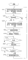
Fig. 2 is the workflow diagram according to the battery charger of embodiment of the present invention.
Embodiment
Below, describe battery charger according to the preferred embodiment of the present invention with reference to the accompanying drawings.Fig. 1 is the schematic diagram of battery charger, shows the structure of battery charger.During use, battery charger is connected on the AC power 1, and battery pack 2 is put into battery charger.As shown in Figure 1, be provided with a pair of splicing ear, be used for cross-over connection battery pack 2.Battery pack 2 comprises battery unit 2a and thermistor 2b that a plurality of polyphones connect, and thermistor 2a is as a temperature-sensing element here.The battery unit that uses in the battery pack 2 both can be a nickel-cadmium cell, also can be ni-MH battery, perhaps lithium ion battery.
Battery charger comprises first a power supply circuits 10A to battery pack 2 chargings, and the first power supply circuits 10A is made up of rectifying/filtering circuit 10 and switching circuit 20.During use, rectifying/filtering circuit 10 is linked to each other with AC power 1, rectifying/filtering circuit 10 comprises a full-wave rectifier 11 and a filter capacitor 12.Switching circuit 20 links to each other with the output of full-wave rectifier 11, and switching circuit 20 comprises a high frequency transformer 21, MOSFET pipe 22 and PWM (pulse-width modulation) control integrated circuit 23.
A rectifying/filtering circuit 30 links to each other with the secondary winding of high frequency transformer 21, and it comprises diode 31, diode 32, a choke 33 and a filter capacitor 34.The output of rectifying/filtering circuit 30 links to each other with battery pack 2, and gives battery pack 2 chargings by the energy that rectifying/filtering circuit 30 produces.
Battery charger comprises a resistance 3 and a charging current control circuit 60.Resistance 3 links to each other with battery pack 2, and it is used to detect the electric current that flows into battery pack 2 here as current detector.
Charging current control circuit 60 comprises operational amplifier 61, operational amplifier 62, resistance 63-66 and diode 67.Charging current detects resistance 3 detected charging currents and is added on the operational amplifier 61, uses operational amplifier 61, is reversed amplification with the charging current correspondent voltage.The output voltage of operational amplifier 61 and charging current are provided with between the reference voltage that circuit 7 is provided with has a difference, and operational amplifier 62 amplifies this difference, and the difference after will amplifying is fed to PWM control integrated circuit 23 by optical coupler 5b.
Charging current is provided with circuit 7 by at the first supply power voltage V
CCAnd the resistance 7a of two polyphones between the ground and resistance 7b composition.The voltage that obtains on the resistance 7b is as reference voltage, and will offer charging current control circuit 60.Charging current control circuit 60 relatively with flow into the charging current correspondent voltage in the battery pack 2 and the output voltage of circuit 7 be set from charging current, the output voltage that charging current is provided with circuit 7 has characterized the reference charge electric current.
In order to detect the voltage at battery pack 2 terminal two ends, be provided with a battery voltage detection circuit 40.Battery voltage detection circuit 40 comprises the resistance 41 and 42 of two polyphones at the terminal two ends that are connected across battery pack 2.The voltage that obtains on the resistance 42 offers microcomputer 50 by an A/D converter 52.
Battery charger also comprises output voltage controlling circuit 80, and output voltage controlling circuit 80 has an operational amplifier 81, resistance 82-85 and a diode 86.From the voltage of output voltage detecting circuit 4 be provided with from output voltage between the voltage of circuit 6 outputs and have a difference, operational amplifier 81 amplifies this difference, and the difference after will amplifying is fed to PWM control integrated circuit 23 by optical coupler 5b, controls the output voltage of secondary commutation/filter circuit 30 whereby.
Output voltage is provided with circuit 6 to be made up of resistance 6a, 6b and 6c, and resistance 6a and 6b are connected in the first supply power voltage V here
CCAnd between the ground.Resistance 6c is connected between the connected node of the output port 53d of microcomputer 50 and resistance 6a, 6b.
When charging current control circuit 60 work, for charging current being remained on a steady state value, PWM control integrated circuit 23 control MOSFET pipes 22 carry out the ON/OFF action; And when in output voltage controlling circuit 80 work, for charging voltage being remained on a steady state value, PWM control integrated circuit 23 also will be controlled MOSFET pipe 22 and carry out the ON/OFF action.Especially, when carrying out constant current control, the pulse duration that produces and be added on the high frequency transformer 21 changes between wide, narrow, and when charging current was big, pulse duration was narrow, and when charging current was little, pulse duration was wide.Before this electric current is applied to battery pack 2, use rectifying/filtering circuit 30 that this electric current is filtered into direct current.Therefore, the function of current sense resistor 3, charging current control circuit 60, optical coupler 5b, switching circuit 20 and rectifying/filtering circuit 30 is exactly that charging current value with battery pack 2 maintains charging current the current value that circuit 7 is provided with is set.
Battery charger also comprises a battery temperature testing circuit 90.Circuit 90 is connected in the first supply power voltage V by two
CCAnd the resistance between the ground 91,92 constitutes.The connected node of resistance 91 and resistance 92 links to each other with thermistor 2b, also links to each other with the A/D converter 52 of microcomputer 50 simultaneously, is added on the microcomputer 50 to cause the voltage that obtains on the resistance 92.Voltage on the resistance 92 changes along with the variation of thermistor 2b resistance, temperature that therefore can pilot cell.
Battery charger is provided with a cooling fan 8 and cooling fan drive circuit 9.Cooling fan 8 is provided with by battery pack 2, thereby battery pack 2 is cooled off.Drive circuit 9 is by a resistance 9b between a triode 9a, the base stage that is connected triode 9a and the output port 53a, and is connected the base stage of triode 9a and the resistance 9c between the emitter forms.Utilize this structure, when the second supply power voltage V is provided
CC2, and the output port 53a of microcomputer 50 is when the high flat signal of drive circuit 9 output, and cooling fan 8 is driven.With the second supply power voltage V
CCThe ratio first supply power voltage V that 2 magnitude of voltage is provided with
CCGreatly.
Battery charger also comprises one second power supply circuits 100.Second power supply circuits 100 comprise a Switching Power Supply, first generating circuit of service voltage, second generating circuit of service voltage.First generating circuit of service voltage produces the first supply power voltage V
CC, second generating circuit of service voltage produces the second supply power voltage Vcc2.The first supply power voltage Vcc offers that microcomputer 50, output voltage are provided with circuit 6, charging current is provided with circuit 7, battery temperature testing circuit 90 and optical coupler 5b and 5c.The second supply power voltage Vcc2 offers fan drive circuit 9.
Second power supply circuits 100 comprise: the switching device 102, the rectifier diode 103 that is connected with secondary winding 101b electrode line and electrode line that is connected across secondary winding 10b and the filtering capacitor on the negative line 104 that have the power transformer 101 of elementary winding 101a and secondary winding 101b, be connected in series with elementary winding 101a.
Second power supply circuits 100 also comprise three terminal regulator 111, filter capacitor 112 and reseting circuit 113.Three terminal regulator 111 has the input that is connected with secondary winding 101b electrode line, the output and the earth terminal that is connected with the secondary winding 101b negative line of transformer 101 that produces the first supply power voltage Vcc.Reseting circuit 113 is connected between the output and secondary winding 101b negative line of three terminal regulator 111, and also is connected with the RESET input mouth 54 of microcomputer 50.Reseting circuit 113 gives 54 outputs of the RESET input mouth a reset signal, thereby makes microcomputer 50 be returned to initial condition.Second power supply circuits 100 also comprise the filter capacitor 110 that is connected between secondary winding 101b electrode line and the negative line, are used to produce the second supply power voltage Vcc2.
Second power supply circuits 100 also comprise: resistance 107,108 and 109, shunt regulator 106, feedback unit (optical coupler) 105.A terminal of resistance 109 is connected with the output port 53c of microcomputer 50, and another terminal is connected with the connected node of the resistance 107,108 that is connected in series.Resistance 107 and 108 is connected between the electrode line and negative line of secondary winding 101b.The voltage that obtains on the resistance 108 is determined according to the instruction of microcomputer 50 output 53c output.Therefore the voltage at resistance 108 two ends is controlled shunt regulator 106, and the corresponding signal of the instruction of sending with microcomputer 50 output port 53c is delivered to switching device 102 places via feedback unit 105.
Instruct in response to first instruction and second that output port 53c sends, thereby control switching optionally provides the first output V1 and the second output V2.First generating circuit of service voltage produces the first supply power voltage Vcc in response to first and second output V1, the V2, and second generating circuit of service voltage only produces the second supply power voltage Vcc2 in response to the second output V2.The second output V2 can be arranged to the second supply power voltage Vcc2.
Battery charger also comprises the 3rd power supply circuits 120 that are used for to 23 power supplies of PWM control integrated circuit.PWM control integrated circuit 23 can be worked when by the 3rd power supply circuits 120 it being powered, and does not work when the 3rd power supply circuits 120 are not powered to it.The 3rd power supply circuits 120 comprise: with the magnetic-coupled tertiary winding 101c of elementary winding 101a of second power supply circuits 100, the diode 121 that is connected with the electrode line of tertiary winding 101c and electrode line that is connected across tertiary winding 101c and the electric capacity on the negative line.The 3rd power supply circuits 120 are powered to PWM control integrated circuit 23 when Switching Power Supply is exported the second voltage V2, and do not give the PWM control integrated circuit 23 power supplies when Switching Power Supply is exported the first voltage V1.
Below, with reference to the method for the flow chart description of figure 2 control battery charger.
When the device that charges the battery adds when powering on, can finish initial setting up, so execution in step 101 to microcomputer 50 output port 53a, 53b, 53c and 53d.In step 101, the output of Switching Power Supply is about to impose on the voltage of the pressurizer 111 of first generating circuit of service voltage, is arranged to V1.Voltage V1 makes pressurizer 111 produce the minimum voltage of the first supply power voltage Vcc.That is to say that when applying voltage V1 for pressurizer 111, pressurizer 111 can produce the first supply power voltage Vcc.In order to produce the first supply power voltage Vcc, first command signal is sent and is delivered to switching device 102 via resistance 107-109, shunt regulator 106 and feedback unit 105 from the output port 53c of microcomputer 50.Especially, output port 53c is set to high impedance value, can control shunt regulator 106 like this and produce an output variable, and this output variable is determined according to the voltage at resistance 107 and 108 connected node places, this amount is determined by the high impedance value at output port 53c place conversely speaking.Therefore, feedback unit 105 provides a signal for switching device 102, and this signal is corresponding to the high impedance value at output port 53c place.
When Switching Power Supply produced voltage V1, the 3rd power supply circuits 120 had produced an output voltage, were used to make PWM control integrated circuit 23 to lose efficacy.Therefore, the first power supply circuits 10A does not work, so battery pack 2 does not obtain from the first power supply circuits 10A.
Next, in step 102, CPU51 determines whether battery pack 2 places battery charger or be not connected with splicing ear.Whether battery pack 2 places battery charger to determine according to the voltage that battery voltage detection circuit 40 imposes on microcomputer 50, perhaps determines according to the voltage of battery temperature testing circuit 90.
When CPU51 had determined that battery pack 2 places battery charger (S102: be), the output of Switching Power Supply was set to V2 to produce the second supply power voltage Vcc2 in second generating circuit of service voltage.Meanwhile, apply voltage V2 at its input also for first generating circuit of service voltage, voltage V2 will be higher than voltage V1, so the first supply power voltage Vcc exports continuously from its output.In order to produce the second supply power voltage Vcc2, second command signal is sent and is delivered to switching device 102 places via resistance 107-109, shunt regulator 106 and feedback unit 105 from the output port 53c of microcomputer 50.Specifically, output port 53c is set to low impedance value, can control shunt regulator 106 like this and produce an output variable, and this output variable is determined according to the voltage at resistance 107 and 108 connected node places, that is to say that this amount is determined by the low impedance value on the output port 53c.Therefore, feedback unit 105 provides a signal for switching device 102, and this signal is corresponding to the low impedance value at output 53c place.
When second generating circuit of service voltage produced voltage V2, the 3rd power supply circuits 120 had produced an output voltage, were used to make 23 work of PWM control integrated circuit.Therefore, first power supply circuits 10A work.And then when PWM control integrated circuit 23 received the charging commencing signal that microcomputer 50 sends, battery pack 2 can be charged by the electric energy that the first power supply circuits 10A provides.Because voltage V2 will be higher than voltage V1, various parts keep operating state so three terminal regulator 111 can produce the first supply power voltage Vcc continuously.
Next, in step 104, the output port 53a of microcomputer 50 is set to high level, and then allows the second supply power voltage Vcc2 to drive cooling fan 8.Afterwards, among the step S105, output 53b sends the charging commencing signal for PWM integrated circuit 23 via optical coupler 5c, to begin giving battery pack 2 chargings with charging current I.
After battery pack 2 began charging, microcomputer 50 determined in step 106 whether battery pack 2 has arrived full state.Known in this area have variously be used for determining whether battery reaches the methods of full state, such as-△ V method, dT/dt method.In simple terms ,-△ V method is to determine whether battery is full of at cell voltage when peak value has descended a predetermined voltage.The dT/dt method is to determine whether battery is full of when the battery temperature gradient surpasses predetermined value.Above-mentioned and other method of determining the battery full state has been disclosed, for example, and at Japanese Patent Application Publication Nos.SHO-62-193518, HEI-2-246793 and the open No.HEI-3-34638 of Japanese utility model application.
When having determined that battery pack 2 has been full of electricity (S106: be), microcomputer 50 sends the charging stop signal to stop charging (step 107) for PWM control integrated circuit 23 via optical coupler 5c.When CPU51 determines battery pack 2 (step 108: be) when charger is pulled down, its output port of CPU51 53a is set to low level to drive cooling fan 8 (step 109).Afterwards, program forwards step 101 to, and the output voltage of Switching Power Supply is set to voltage V1 in this step.
As described, can between standby period, realize low power consumption according to the battery charger of previous embodiment.
Though the present invention is described in detail with reference to concrete execution mode, for a person skilled in the art, can make various changes and adjustment under the condition that does not depart from spirit of the present invention, scope of the present invention is defined by the following claims.
For example, above-described execution mode can change into and only drive cooling fan 8 when battery temperature is higher than predetermined value.
Claims (8)
1, a kind of battery charger, comprising:
A pair of splicing ear, itself and secondary cell cross-over connection;
First power supply circuits, its with this splicing ear to being connected and giving this secondary cell power supply;
Second power supply circuits, its generation will offer first voltage of first parts and offer second voltage of second parts, and second magnitude of voltage is greater than first magnitude of voltage;
First parts of when first voltage is provided, working;
Second parts of when second voltage is provided, working; And
Control section, it controls first power supply circuits and second power supply circuits, so that first power supply circuits were lost efficacy and the second power supply circuits work during to cross-over connection with this splicing ear at secondary cell, when secondary cell and described splicing ear make first power supply circuits and the second power supply circuits work during to cross-over connection, wherein secondary cell not with this splicing ear during to cross-over connection these second power supply circuits only produce first voltage, and produce first voltage and second voltage during to cross-over connection at secondary cell and this splicing ear.
2, battery charger according to claim 1 is characterized in that:
This control section comprises a microcomputer, and wherein these second power supply circuits are given this microcomputer power supply, makes in not this microcomputer work during to cross-over connection with this splicing ear of secondary cell.
3, battery charger according to claim 1 is characterized in that this control section comprises battery connection detection circuit, and it is to detecting with the secondary cell of splicing ear to cross-over connection.
4, a kind of battery charger, comprising
A pair of splicing ear, itself and secondary cell cross-over connection;
First power supply circuits, its with this splicing ear to being connected and giving this secondary cell power supply;
First parts of when first voltage is provided, working;
Second parts of when second voltage is provided, working, second voltage is higher than first voltage;
Second power supply circuits, its generation will offer first voltage of first parts and offer second voltage of second parts; And
Control section; It controls first power supply circuits and second power supply circuits; So that first power supply circuits were lost efficacy and the second power supply circuits work with this splicing ear during to cross-over connection at secondary cell; When secondary cell and described splicing ear make first power supply circuits and the second power supply circuits work during to cross-over connection; Wherein secondary cell not with this splicing ear during to cross-over connection these second power supply circuits produce first voltage; And produce first and second voltages during to cross-over connection at secondary cell and this splicing ear
It is characterized in that these second power supply circuits only produce first voltage in response to first instruction that control section sends, and produce first and second voltages in response to second instruction that control section sends.
5, battery charger according to claim 4 is characterized in that second power supply circuits comprise:
Switching Power Supply, controlled first instruction of sending in response to control section respectively of this Switching Power Supply and second Instruction Selection ground provide first to export and second export;
First voltage generation circuit, it produces first voltage in response to first and second outputs;
Second voltage generation circuit, it produces second voltage in response to second output.
6, battery charger according to claim 5, it is characterized in that first voltage generation circuit comprise have input terminal, three terminal pressurizers of lead-out terminal and earth terminal, wherein this input terminal is connected with Switching Power Supply, and this lead-out terminal is exported first voltage.
7, battery charger according to claim 5, it is characterized in that Switching Power Supply comprises the transformer with an elementary winding and a secondary winding, also comprise a switching device, this switching device is connected with control section optionally to receive first and second instructions that control section sends, and this switching device also is connected with the elementary windings in series of transformer, so that this switching device is carried out and the corresponding on/off switch operation of first and second instructions.
8, battery charger according to claim 7 is characterized in that this control section comprises the tertiary winding, the elementary winding magnetic coupling of this tertiary winding and transformer.
Applications Claiming Priority (2)
| Application Number | Priority Date | Filing Date | Title |
|---|---|---|---|
| JP2004148446 | 2004-05-18 | ||
| JP2004148446A JP4148183B2 (en) | 2004-05-18 | 2004-05-18 | Charger |
Publications (2)
| Publication Number | Publication Date |
|---|---|
| CN1700559A CN1700559A (en) | 2005-11-23 |
| CN100481671C true CN100481671C (en) | 2009-04-22 |
Family
ID=35374579
Family Applications (1)
| Application Number | Title | Priority Date | Filing Date |
|---|---|---|---|
| CNB2005100792232A Expired - Fee Related CN100481671C (en) | 2004-05-18 | 2005-05-18 | Battery charger |
Country Status (4)
| Country | Link |
|---|---|
| US (1) | US7439708B2 (en) |
| JP (1) | JP4148183B2 (en) |
| CN (1) | CN100481671C (en) |
| DE (1) | DE102005022761A1 (en) |
Families Citing this family (18)
| Publication number | Priority date | Publication date | Assignee | Title |
|---|---|---|---|---|
| JP4507191B2 (en) | 2005-03-11 | 2010-07-21 | 日立工機株式会社 | Battery charger |
| US7990110B2 (en) * | 2006-11-03 | 2011-08-02 | Bedini John C | Circuits and related methods for charging a battery |
| US8330414B2 (en) | 2006-11-08 | 2012-12-11 | Panasonic Corporation | Contactless battery charger, electronic device, battery pack, and contactless charging system |
| US8169196B2 (en) * | 2007-06-27 | 2012-05-01 | Sony Mobile Communications Ab | Charging device |
| US7960944B2 (en) * | 2007-09-05 | 2011-06-14 | Eveready Battery Company, Inc. | Power supply that supplies power to and communicates with an electrical appliance |
| JP2010178516A (en) * | 2009-01-29 | 2010-08-12 | Sanyo Electric Co Ltd | Plug-in battery charger |
| JP2010239788A (en) * | 2009-03-31 | 2010-10-21 | Hitachi Koki Co Ltd | Charging apparatus |
| DE102009028322A1 (en) * | 2009-08-07 | 2011-02-10 | Robert Bosch Gmbh | Charger for charging a battery pack |
| JP5549184B2 (en) | 2009-10-29 | 2014-07-16 | 日立工機株式会社 | Charger |
| US8543859B2 (en) * | 2010-03-12 | 2013-09-24 | Dell Products, Lp | Host detection circuit powered from primary side of the alternating current adaptor for detecting changes to a power level pulse of an information handling system |
| JP2012143123A (en) * | 2010-12-14 | 2012-07-26 | Makita Corp | Charger |
| JP2012130123A (en) | 2010-12-14 | 2012-07-05 | Makita Corp | Charger |
| CN102570559A (en) * | 2012-01-17 | 2012-07-11 | 浙江凯能科技有限公司 | Storage battery charger |
| WO2013155670A1 (en) * | 2012-04-16 | 2013-10-24 | Abb Technology Ltd. | Standby power supply circuit for 2-wire bus intercom system and apparatus thereof |
| WO2014073182A1 (en) * | 2012-11-07 | 2014-05-15 | 三洋電機株式会社 | Charger |
| DE102014219787A1 (en) | 2014-09-30 | 2016-03-31 | Robert Bosch Gmbh | Switching power supply with at least one power section and at least one auxiliary power supply |
| US11031803B2 (en) * | 2017-10-20 | 2021-06-08 | Via Labs, Inc. | Start-up apparatus for battery management circuit and battery management system having the same |
| EP3490052B1 (en) * | 2017-11-24 | 2019-10-02 | Samsung SDI Co., Ltd. | Temperature sensor thermal contact testing method and circuit |
Family Cites Families (6)
| Publication number | Priority date | Publication date | Assignee | Title |
|---|---|---|---|---|
| JPH0681427B2 (en) | 1986-02-20 | 1994-10-12 | 松下電工株式会社 | Charger control circuit |
| JPH02246739A (en) | 1989-03-15 | 1990-10-02 | Matsushita Electric Works Ltd | Charging control circuit |
| JPH0334638A (en) | 1989-06-30 | 1991-02-14 | Nec Corp | Circuit switching method |
| JP2003116230A (en) | 2001-10-03 | 2003-04-18 | Sony Corp | Battery pack charger and dc power supply unit |
| TWI230493B (en) * | 2002-10-11 | 2005-04-01 | Hitachi Koki Kk | Charging apparatus |
| JP4536997B2 (en) * | 2002-11-29 | 2010-09-01 | 日立工機株式会社 | Charger |
-
2004
- 2004-05-18 JP JP2004148446A patent/JP4148183B2/en active Active
-
2005
- 2005-05-18 CN CNB2005100792232A patent/CN100481671C/en not_active Expired - Fee Related
- 2005-05-18 DE DE102005022761A patent/DE102005022761A1/en not_active Withdrawn
- 2005-05-18 US US11/131,359 patent/US7439708B2/en not_active Expired - Fee Related
Also Published As
| Publication number | Publication date |
|---|---|
| CN1700559A (en) | 2005-11-23 |
| JP2005333708A (en) | 2005-12-02 |
| US20050258800A1 (en) | 2005-11-24 |
| DE102005022761A1 (en) | 2006-02-02 |
| JP4148183B2 (en) | 2008-09-10 |
| US7439708B2 (en) | 2008-10-21 |
Similar Documents
| Publication | Publication Date | Title |
|---|---|---|
| CN100481671C (en) | Battery charger | |
| JP4507191B2 (en) | Battery charger | |
| JP5029862B2 (en) | Charger | |
| US7652450B2 (en) | Secondary battery charging device | |
| EP1653584A2 (en) | Battery charging apparatus | |
| US20060125449A1 (en) | Duty cycle controller for high power factor battery charger | |
| WO1989008343A1 (en) | Battery charger | |
| CN101499674A (en) | Charging system for charging battery pack | |
| US5402055A (en) | AC adapter including differential comparator for tracking battery voltage during trickle charge | |
| CN103503272A (en) | Power supply device, inverter device, power tool | |
| JP3772665B2 (en) | Battery charger | |
| JP4817054B2 (en) | Charger | |
| JP3213399B2 (en) | Charging method | |
| JP2002010508A (en) | Apparatus and method for charging | |
| CN214176969U (en) | Wide voltage range charging conversion circuit and charging device | |
| AU2007101218A4 (en) | A Lithium Battery Pack and System for Charging the Same | |
| JPH11150879A (en) | Charging device of battery | |
| CN212784852U (en) | Battery management system for base station standby power supply | |
| JP4085794B2 (en) | Battery charger | |
| CN201230216Y (en) | High-frequency charger | |
| JP3369858B2 (en) | Rechargeable battery charging method | |
| JP2004023975A (en) | Power supply device | |
| CN116365630A (en) | Energy supply device | |
| CN116352660A (en) | Electric tool | |
| JPH1169655A (en) | Secondary-battery charging device and electronic apparatus |
Legal Events
| Date | Code | Title | Description |
|---|---|---|---|
| C06 | Publication | ||
| PB01 | Publication | ||
| C10 | Entry into substantive examination | ||
| SE01 | Entry into force of request for substantive examination | ||
| C14 | Grant of patent or utility model | ||
| GR01 | Patent grant | ||
| CF01 | Termination of patent right due to non-payment of annual fee |
Granted publication date: 20090422 Termination date: 20180518 |
|
| CF01 | Termination of patent right due to non-payment of annual fee |