JP3772665B2 - Battery charger - Google Patents
Battery charger Download PDFInfo
- Publication number
- JP3772665B2 JP3772665B2 JP2000350718A JP2000350718A JP3772665B2 JP 3772665 B2 JP3772665 B2 JP 3772665B2 JP 2000350718 A JP2000350718 A JP 2000350718A JP 2000350718 A JP2000350718 A JP 2000350718A JP 3772665 B2 JP3772665 B2 JP 3772665B2
- Authority
- JP
- Japan
- Prior art keywords
- battery
- set value
- active
- change
- value corresponding
- Prior art date
- Legal status (The legal status is an assumption and is not a legal conclusion. Google has not performed a legal analysis and makes no representation as to the accuracy of the status listed.)
- Expired - Fee Related
Links
Images
Classifications
-
- H—ELECTRICITY
- H02—GENERATION; CONVERSION OR DISTRIBUTION OF ELECTRIC POWER
- H02J—ELECTRIC POWER NETWORKS; CIRCUIT ARRANGEMENTS OR SYSTEMS FOR SUPPLYING OR DISTRIBUTING ELECTRIC POWER; SYSTEMS FOR STORING ELECTRIC ENERGY
- H02J7/00—Circuit arrangements for charging or discharging batteries or for supplying loads from batteries
- H02J7/485—Circuit arrangements for charging or discharging batteries or for supplying loads from batteries with provisions for charging different types of batteries
-
- H—ELECTRICITY
- H02—GENERATION; CONVERSION OR DISTRIBUTION OF ELECTRIC POWER
- H02J—ELECTRIC POWER NETWORKS; CIRCUIT ARRANGEMENTS OR SYSTEMS FOR SUPPLYING OR DISTRIBUTING ELECTRIC POWER; SYSTEMS FOR STORING ELECTRIC ENERGY
- H02J7/00—Circuit arrangements for charging or discharging batteries or for supplying loads from batteries
- H02J7/02—Circuit arrangements for charging or discharging batteries or for supplying loads from batteries for charging batteries from AC mains by converters
- H02J7/04—Regulation of charging current or voltage
-
- H—ELECTRICITY
- H02—GENERATION; CONVERSION OR DISTRIBUTION OF ELECTRIC POWER
- H02J—ELECTRIC POWER NETWORKS; CIRCUIT ARRANGEMENTS OR SYSTEMS FOR SUPPLYING OR DISTRIBUTING ELECTRIC POWER; SYSTEMS FOR STORING ELECTRIC ENERGY
- H02J7/00—Circuit arrangements for charging or discharging batteries or for supplying loads from batteries
- H02J7/90—Regulation of charging or discharging current or voltage
- H02J7/96—Regulation of charging or discharging current or voltage in response to battery voltage
-
- H—ELECTRICITY
- H02—GENERATION; CONVERSION OR DISTRIBUTION OF ELECTRIC POWER
- H02J—ELECTRIC POWER NETWORKS; CIRCUIT ARRANGEMENTS OR SYSTEMS FOR SUPPLYING OR DISTRIBUTING ELECTRIC POWER; SYSTEMS FOR STORING ELECTRIC ENERGY
- H02J2207/00—Details of circuit arrangements for charging or discharging batteries or supplying loads from batteries
- H02J2207/20—Charging or discharging characterised by the power electronics converter
-
- H—ELECTRICITY
- H02—GENERATION; CONVERSION OR DISTRIBUTION OF ELECTRIC POWER
- H02J—ELECTRIC POWER NETWORKS; CIRCUIT ARRANGEMENTS OR SYSTEMS FOR SUPPLYING OR DISTRIBUTING ELECTRIC POWER; SYSTEMS FOR STORING ELECTRIC ENERGY
- H02J7/00—Circuit arrangements for charging or discharging batteries or for supplying loads from batteries
- H02J7/80—Circuit arrangements for charging or discharging batteries or for supplying loads from batteries including monitoring or indicating arrangements
- H02J7/82—Control of state of charge [SOC]
- H02J7/825—Detection of fully charged condition
Landscapes
- Engineering & Computer Science (AREA)
- Power Engineering (AREA)
- Charge And Discharge Circuits For Batteries Or The Like (AREA)
- Secondary Cells (AREA)
Description
【0001】
【発明が属する技術分野】
本発明は例えばコードレス電動工具等の携帯用機器等の電源として用いられているニッケルカドミウム電池(以下ニカド電池という)やニッケル水素電池等の電池を充電する充電装置に関するものである。
【0002】
【従来の技術】
ニッケル水素電池やニカド電池を充電する充電装置の満充電検出方法は種々提案されている。定電流充電で充電末期のピーク値からの降下電圧により検出する−ΔV検出方法より過充電となる恐れの少ない充電時の各サンプリング幅における最新の電圧変化量を演算し、その変化量が第1設定値以上上昇すると共に上昇後の最新変化量が第2設定値以下になったら満充電と判断する満充電検出法を特開平7−184329号により提案した。
【0003】
【発明が解決しようとする課題】
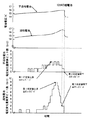
この満充電検出法は前記第1設定値及び第2設定値が固定値であるため、新品の電池や長期放置された電池のような不活性電池と、充放電を繰り返した活性な電池では、図4に示すように充電末期のピークの出現が異なるため、不活性電池または活性な電池を両方とも確実に満充電検出ができない恐れがある。
【0004】
すなわち、図4の場合は第1設定値及び第2設定値を不活性電池に合せているため、活性な電池の満充電を応答性よく検出することができなくなり、結局充電末期のピークが通り過ぎた後に充電を終了させることになり過充電になる恐れがある。
【0005】
逆に第1設定値及び第2設定値を活性電池に合せた場合では、不活性電池の満充電を応答性よく検出することができなくなり、第1設定値以上の電圧上昇を検出できれば満充電前で充電を終了させることになり、また第1設定値以上の電圧上昇を検出できなければ過充電を生じる恐れがある。
【0006】
また、近年電池の高容量化のニーズに対し、ニカド電池に代わり、ニッケル・水素電池の需要が急増しているが、この電池は満充電時のピークの出現がニカド電池に比べ小さく上記した同様の問題がある。
【0007】
本発明の目的は、上記した従来技術の欠点をなくし、如何なる状態の電池を充電しても応答性よく確実に満充電を判別できるようにすることである。
【0008】
【課題を解決するための手段】
上記目的は、前記電池電圧変化量に対応して前記第1設定値及び第2設定値を制御することにより達成される。
【0009】
また前記第1設定値を超えた時の電池電圧変化量に対応して第2設定値を制御するようにしてもよい。
【0010】
更に電池電圧変化量が最大値になった時からこの最大値から第4設定値以下に低下した時に満充電と判断してもよく、この場合変化量最大値に対応して第4設定値を制御するようにすることも可能である。
【0011】
【発明の実施の形態】
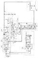
図1は本発明充電装置の一実施形態を示す回路図である。図において、1は交流電源、2は複数の充電可能な素電池を直列に接続した電池組、3は電池組2に流れる充電電流を検出する電流検出手段、4は充電の開始及び停止を制御する信号を伝達する充電制御信号伝達手段、5は充電電流の信号を後述するPWM制御IC23に帰還する充電電流信号伝達手段である。充電制御伝達信号手段4と充電電流信号伝達手段5はホトカプラ等からなる。10は全波整流回路11と平滑用コンデンサ12からなる整流平滑回路、20は高周波トランス21、MOSFET22とPWM制御IC23からなるスイッチング回路である。PWM制御IC23はMOSFET22の駆動パルス幅を変えて整流平滑回路10の出力電圧を調整するスイッチング電源ICである。30はダイオード31、32、チョークコイル33と平滑用コンデンサ34からなる整流平滑回路、40は抵抗41、42からなる電池電圧検出手段で、電池組2の端子電圧を分圧する。50は演算手段(CPU)51、ROM52、RAM53、タイマ54、A/Dコンバータ55、出力ポート56、リセット入力ポート57からなるマイコンである。CPU51は1サンプリング毎に最新の電池電圧と複数サンプリング前の電池電圧を比較する。RAM53は所定数の過去のサンプリング電圧等を記憶する電池電圧記憶手段である。60は演算増幅器61、62、抵抗63〜66からなる充電電流制御手段、70は電源トランス71、全波整流回路72、平滑コンデンサ73、3端子レギュレータ74、リセットIC75からなる定電圧電源で、マイコン50、充電電流制御手段60等の電源となる。リセットIC75はマイコン50を初期状態にするためにリセット入力ポート57にリセット信号を出力する。80は充電電流を設定する充電電流設定手段であって、前記出力ポート56bからの信号に対応して演算増幅器62の反転入力端に印加する電圧値を変えるものである。
【0012】
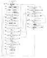
次に図1の回路図、図2のフローチャートを参照して、本発明充電装置の一実施形態の動作を説明する。
【0013】
電源を投入するとマイコン50は、電池組2の接続待機状態となる(ステップ101)。電池組2を接続すると、マイコン50は電池電圧検出手段40からの信号により電池組2の接続を判別し、出力ポート56より充電制御信号伝達手段4を介してPWM制御IC23に充電開始信号を伝達すると共に出力ポート56より充電電流設定手段80を介して、充電電流設定基準電圧値Viを演算増幅器62に印加し、充電電流Iで充電を開始する(ステップ102)。充電開始と同時に電池組2に流れる充電電流を電流検出手段3により検出し、この充電電流に対応する電圧と充電電流設定基準値Viとの差を充電電流制御手段60より信号伝達手段5を介してPWM制御IC23に帰還をかける。すなわち、充電電流が大きい場合はパルス幅を狭めたパルスを、逆の場合はパルス幅を広げたパルスを高周波トランス21に与え整流平滑回路30で直流に平滑し、充電電流を一定に保つ。すなわち電流検出手段3、充電電流制御手段60、信号伝達手段5、スイッチング回路20、整流平滑回路30を介して充電電流を設定電流値Iとなるように制御する。
【0014】
次いで満充電検出制御を行う。電池電圧記憶手段53の記憶データの6サンプリング前までの電圧Vi-06、Vi-05、……、Vi-01と、最新の電池電圧と6サンプリング前の電池電圧Vi-06との差すなわち電池電圧変化量(以下単に変化量という)△Vi-06、最小電池電圧変化量△Vmin、変化量△Vi-06と最小電池電圧変化量△Vminとの差(以下これを差変化量という)が後述する第1設定値を超えた時の差変化量に対応して記憶する2個の電圧上昇判別フラグFlag1、Flag2をイニシャルリセットし(ステップ103)、電池電圧サンプリングタイマをスタートさせる(ステップ104)。サンプリングタイマ時間が△tを経過したら(ステップ105)、再度サンプリングタイマをスタートさせる(ステップ106)。
【0015】
次いで電池電圧を電池電圧検出手段40で分圧した分圧値をA/Dコンバータ55でA/D変換し、電池電圧Vinとして取り込む(ステップ107)。そして演算手段51にてVinと6サンプリング前のデータVi-06との差すなわち変化量△Vi-06=Vin−Vi-06を求め(ステップ108)、ステップ109、110において差変化量が前記第1設定値を超えると共に差変化量がK2以上だった時に1となるFlag2、K1以上だった時に1となるFlag1が1となっているか否かを判断する。すなわち差変化量が既に第1設定値を超えたか否かを判断する。ステップ109でFlag2が1の場合ステップ120にスキップする。ステップ109でFlag2が0の場合はステップ110に進みFlag1の値を判断し、既に小さい方の第1設定値K1を超えたか否かの判断を行う。Flag1が1の場合にはステップ118にスキップする。Flag1が0の場合はステップ111に進む。
【0016】
次いで前記差変化量が小さい方の第1設定値K1以上か否かの判断を行い(ステップ111)、K1以上ならステップ117にスキップし、K1未満なら変化量が負か否かを判断し(ステップ112)、負でないなら変化量と変化量最小値の大小を比較し(ステップ114)、変化量が変化量最小値未満なら変化量を変化量最小値とし(ステップ115)てステップ116に進む。変化量が変化量最小値以上ならステップ116にスキップする。ステップ116においては、Vi-05→Vi-06、Vi-04→Vi-05、………、Vin→Vi-01とそれぞれの電池電圧データを1サンプリング前の記憶エリアに移し替え、その後ステップ105に戻る。
【0017】
ステップ111において差変化量が第1設定値K1以上なら第1設定値K1を超えたと判断し、Flag1を1にセット(ステップ117)しステップ118に進む。
【0018】
ステップ118においては差変化量がK2以上か否かを判断し、K2以上ならFlag2を1にセット(ステップ119)してステップ120に進み、K2未満ならステップ121にスキップする。
【0019】
すなわちステップ111において第1設定値K1を超えた時一旦負活性電池と認識し、ステップ118でK2以上なら活性電池と認識を改め、ステップ118でK2未満なら負活性電池と認識を改めない。
【0020】
ステップ120においては変化量が活性電池に対応する第2設定値S2以上低下したか否かを判断し、低下と判断したすなわち満充電と判断した場合にはステップ122に進んで充電を停止する。ステップ121においては変化量が負活性電池に対応する第2設定値S1(S1<S2)以上低下したかを判断し、低下と判断した場合すなわち満充電と判断した場合にはステップ122に進んで充電を停止する。ステップ120、121において変化量が第2設定値S2(S1)以下ならステップ112に戻る。
【0021】
ステップ122においては前記充電制御信号伝達手段4を介して充電停止信号をPWM制御IC23に伝達して充電を停止する。ステップ123においては電池組2が取り出されるのを判断し、取り出されたら次ぎの電池組2の充電に備えてステップ101に戻る。
【0022】
なお前記第1設定値K1、K2及び第2設定値S1、S2は、変化量または差変化量が満充電近傍において上昇及び低下する値で、電池電圧をA/Dコンバータ55でデジタル値に変換した場合、所定のビット数で表されるもので、K1<K2、S1<S2の関係を有する。
【0023】
上記実施形態においては変化量と変化量最小値との差すなわち差変化量が第1設定値K1、K2を超えたか否かを判断するとしたが、変化量が第1設定値K1、K2を超えたか否かを判断するようにしてもよい。また第1設定値K1、K2を超えた時の変化量または差変化量の値によって活性電池または負活性電池と認識し、第2設定値S1、S2を選択制御するようにしたが、第1設定値を超える前の変化量または差変化量の値によって活性電池か負活性電池と認識し、この認識結果によって第1設定値K1、K2及び第2設定値S1、S2を選択制御するようにしてもよい。
【0024】
上記実施形態によれば電池組2の状態すなわち活性電池、負活性電池に関係なく満充電を正確かつ確実に検出できるようになり、過充電、不足充電となる恐れはなくなる。
【0025】
上記実施形態においては、電池電圧変化量が第1設定値以上上昇すると共に上昇後の最新変化量が第2設定値以下になったら満充電と判断するとしたが、上記特開平7−184329号の図3から明らかな如く、変化量が最大値となった後に変化量が最大値から所定値低下した時点を満充電と判断しても電池電圧がピークに達する前に判断できることには変わりなくこのように判断しても上記実施形態の満充電判断と大差はない。
【0026】
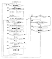
図3はこの思想で満充電を判断するようにしたフローチャートを示すもので以下図1の回路図、図3のフローチャートを参照して本発明の他の実施形態の動作を説明する。
【0027】
ステップ201〜208は図2のステップ101〜108とほぼ同じであり説明を省略する。ステップ203において変化量の最大値△Vmaxが図2にない値で0にイニシャルリセットされる。
【0028】
ステップ209において変化量最大値△Vmaxが第3設定値P2以上か否かを判断し、以上なら活性電池と判断してステップ215にスキップし、未満ならステップ210へ進む。
【0029】
ステップ210において変化量最大値△Vmaxが第3設定値P1(<P2)以上か否かを判断し、以上なら負活性電池と判断してステップ214にスキップし、未満ならステップ211へ進む。
【0030】
ステップ211において変化量と変化量最大値との大小を判断し、変化量が大きければ変化量を変化量最大値とし(ステップ212)てステップ213に進み、変化量が小さければステップ213にスキップする。ステップ213においては上記ステップ116と同様に電池電圧データの移し替えを行う。
【0031】
ステップ214、215においては、変化量が変化量最大値から第4設定値Q1またはQ2(>Q1)以上低下した否かを判断し、低下したのを判断したらステップ216に進んで充電を停止し、低下を判断しなかったらステップ211に戻る。
【0032】
図3の実施形態においても第3設定値P1(P2)を超える時の変化量最大値によって活性電池か負活性電池かを判別し、第4設定値Q1(Q2)を選択するようにしたので、上記実施形態と同様に、電池組2の状態に関係なく満充電を正確かつ確実に検出できるようになる。
【0033】
【発明の効果】
本発明によれば,これにより充電末期の電圧上昇が異なる不活性電池または活性な電池を両方とも確実に満充電検出ができる。
【図面の簡単な説明】
【図1】本発明の一実施形態を示す回路図。
【図2】本発明充電装置の動作の一実施形態を示すフローチャート。
【図3】本発明充電装置の動作の他の実施形態を示すフローチャート。
【図4】本発明による電池組の充電電圧特性を示すグラフ。
【符号の説明】
2は電池組,40は電池電圧検出手段,50はマイコン,60は充電電流制御手段である。[0001]
[Technical field to which the invention belongs]
The present invention relates to a charging device for charging a battery such as a nickel cadmium battery (hereinafter referred to as a nickel cadmium battery) or a nickel metal hydride battery used as a power source for portable equipment such as a cordless electric tool.
[0002]
[Prior art]
Various methods for detecting the full charge of a charging device for charging a nickel metal hydride battery or a nickel cadmium battery have been proposed. The latest voltage change amount at each sampling width at the time of charging, which is less likely to be overcharged than the -ΔV detection method detected by the voltage drop from the peak value at the end of charging in constant current charging, is calculated as the first change amount. Japanese Patent Application Laid-Open No. 7-184329 proposes a full charge detection method for determining that the battery is fully charged when it rises above the set value and the latest change after the rise is below the second set value.
[0003]
[Problems to be solved by the invention]
In this full charge detection method, the first set value and the second set value are fixed values. Therefore, in an inactive battery such as a new battery or a battery left for a long time, and an active battery that is repeatedly charged and discharged, As shown in FIG. 4, since the appearance of the peak at the end of charging is different, there is a possibility that full charge detection cannot be reliably performed for both inactive batteries or active batteries.
[0004]
That is, in the case of FIG. 4, since the first set value and the second set value are matched to the inactive battery, it becomes impossible to detect the full charge of the active battery with good responsiveness, and the peak at the end of charging passes after all. After that, the charging is terminated and there is a risk of overcharging.
[0005]
Conversely, when the first set value and the second set value are matched to the active battery, it becomes impossible to detect the full charge of the inactive battery with good responsiveness, and if the voltage rise above the first set value can be detected, the battery is fully charged. Charging will be terminated earlier, and overcharge may occur if a voltage increase greater than the first set value cannot be detected.
[0006]
In recent years, the demand for nickel-hydrogen batteries, instead of nickel-cadmium batteries, has been increasing rapidly in response to the need for higher capacity batteries. There is a problem.
[0007]
An object of the present invention is to eliminate the above-described drawbacks of the prior art and to determine full charge with high responsiveness even if a battery in any state is charged.
[0008]
[Means for Solving the Problems]
The object is achieved by controlling the first set value and the second set value in accordance with the battery voltage change amount.
[0009]
Further, the second set value may be controlled corresponding to the battery voltage change amount when the first set value is exceeded.
[0010]
Furthermore, when the battery voltage change amount reaches the maximum value, it may be determined that the battery is fully charged when the maximum voltage value drops below the fourth set value. In this case, the fourth set value is set corresponding to the maximum change amount value. It is also possible to control.
[0011]
DETAILED DESCRIPTION OF THE INVENTION
FIG. 1 is a circuit diagram showing an embodiment of the charging device of the present invention. In the figure, 1 is an AC power source, 2 is a battery set in which a plurality of rechargeable cells are connected in series, 3 is a current detecting means for detecting a charging current flowing through the
[0012]
Next, the operation of the embodiment of the charging device of the present invention will be described with reference to the circuit diagram of FIG. 1 and the flowchart of FIG.
[0013]
When the power is turned on, the
[0014]
Next, full charge detection control is performed. The difference between the voltages Vi-06, Vi-05,..., Vi-01 before the 6 sampling of the stored data of the battery voltage storage means 53 and the battery voltage Vi-06 before the 6 samplings, that is, the battery Voltage change amount (hereinafter simply referred to as change amount) ΔVi-06, minimum battery voltage change amount ΔVmin, difference between change amount ΔVi-06 and minimum battery voltage change amount ΔVmin (hereinafter referred to as difference change amount) Two voltage rise determination flags Flag1 and Flag2 stored corresponding to the difference change amount when exceeding a first set value, which will be described later, are initially reset (step 103), and the battery voltage sampling timer is started (step 104). . When the sampling timer time exceeds Δt (step 105), the sampling timer is started again (step 106).
[0015]
Next, the divided voltage value obtained by dividing the battery voltage by the battery voltage detecting means 40 is A / D converted by the A /
[0016]
Next, it is determined whether or not the difference change amount is the first set value K1 or more which is smaller (step 111). If it is greater than K1, the process skips to step 117, and if less than K1, it is determined whether or not the change amount is negative ( Step 112), if it is not negative, the change amount is compared with the minimum change amount value (step 114), and if the change amount is less than the minimum change amount, the change amount is set to the minimum change amount (step 115) and the process proceeds to step 116. . If the change amount is equal to or greater than the change amount minimum value, the process skips to step 116. In
[0017]
If the difference change amount is not less than the first set value K1 in
[0018]
In
[0019]
That is, when the first set value K1 is exceeded in
[0020]
In
[0021]
In
[0022]
The first set values K1 and K2 and the second set values S1 and S2 are values in which the change amount or difference change amount rises and falls near full charge, and the battery voltage is converted into a digital value by the A /
[0023]
In the above embodiment, it is determined whether or not the difference between the change amount and the minimum change amount, that is, the difference change amount exceeds the first set values K1 and K2, but the change amount exceeds the first set values K1 and K2. It may be determined whether or not. In addition, the second set values S1 and S2 are selected and controlled by recognizing the battery as an active battery or a negative active battery based on the amount of change or difference change when the first set values K1 and K2 are exceeded. The active battery or the negative active battery is recognized based on the change amount before the set value or the difference change amount, and the first set values K1, K2 and the second set values S1, S2 are selectively controlled based on the recognition result. May be.
[0024]
According to the above embodiment, full charge can be accurately and reliably detected regardless of the state of the battery set 2, that is, the active battery and the negative active battery, and there is no possibility of overcharging and undercharging.
[0025]
In the above embodiment, when the battery voltage change amount rises by more than the first set value and the latest change amount after the rise becomes less than the second set value, it is determined that the battery is fully charged. As apparent from FIG. 3, even when it is determined that the amount of change has decreased by a predetermined value from the maximum value after the change amount has reached the maximum value, it can still be determined before the battery voltage reaches its peak. Even if it judges so, there is no big difference with the full charge judgment of the said embodiment.
[0026]
FIG. 3 shows a flowchart in which full charge is determined based on this idea. The operation of another embodiment of the present invention will be described below with reference to the circuit diagram of FIG. 1 and the flowchart of FIG.
[0027]
[0028]
In
[0029]
In
[0030]
In
[0031]
In
[0032]
In the embodiment of FIG. 3 as well, the fourth set value Q1 (Q2) is selected by determining whether the battery is the active battery or the negative active battery based on the maximum amount of change when the third set value P1 (P2) is exceeded. As with the above embodiment, full charge can be accurately and reliably detected regardless of the state of the
[0033]
【The invention's effect】
According to the present invention, it is possible to reliably detect full charge of both inactive batteries or active batteries having different voltage increases at the end of charging.
[Brief description of the drawings]
FIG. 1 is a circuit diagram showing an embodiment of the present invention.
FIG. 2 is a flowchart showing an embodiment of the operation of the charging device of the present invention.
FIG. 3 is a flowchart showing another embodiment of the operation of the charging device of the present invention.
FIG. 4 is a graph showing charging voltage characteristics of a battery set according to the present invention.
[Explanation of symbols]
2 is a battery set, 40 is a battery voltage detecting means, 50 is a microcomputer, and 60 is a charging current control means.
Claims (2)
前記第1設定値を活性電池に対応する活性電池対応第1設定値及び不活性電池に対応し活性電池対応第1設定値より小さい不活性電池対応第1設定値とすると共に第2設定値を活性電池に対応する活性電池対応第2設定値及び不活性電池に対応し活性電池対応第2設定値より小さい不活性電池対応第2設定値とし、前記変化量が活性電池対応第1設定値以上となった時活性電池と認識し、その後の変化量が活性電池対応第2設定値以下となった時活性電池の満充電と検出し、前記変化量が活性電池対応第1設定値未満で不活性電池対応第1設定値以上となった時不活性電池と認識し、その後の変化量が不活性電池対応第2設定値以下となった時不活性電池の満充電と検出するようにしたことを特徴とした電池の充電装置。Battery voltage detection means for detecting the battery voltage of the battery to be charged, battery voltage storage means for storing a plurality of sampling battery voltages from the battery voltage detection means, and the difference between the latest sampling battery voltage and a predetermined number of sampling battery voltages, After calculating the amount of change in the battery voltage and detecting whether the amount of change exceeds the first set value, if not, the stored value of the power supply voltage storage means is rewritten, and after the amount of change exceeds the first set value A battery charging device comprising: calculating means for detecting that the amount of change in the latest sampling battery voltage is less than or equal to a second set value smaller than the first set value and determining that the battery is fully charged,
The first set value is a first set value corresponding to an active battery corresponding to an active battery, a first set value corresponding to an inactive battery and smaller than the first set value corresponding to an active battery, and a second set value The second set value corresponding to the active battery corresponding to the active battery and the second set value corresponding to the inactive battery corresponding to the inactive battery are smaller than the second set value corresponding to the active battery , and the amount of change is the first set value corresponding to the active battery. When it becomes above, it is recognized as an active battery, and when the subsequent change amount becomes equal to or less than the second set value corresponding to the active battery, it is detected that the active battery is fully charged, and the change amount is less than the first set value corresponding to the active battery. Recognized as an inactive battery when the value exceeds the first set value corresponding to the inactive battery, and detects that the inactive battery is fully charged when the amount of change thereafter becomes the second set value corresponding to the inactive battery or less. A battery charger characterized by that.
前記第3設定値を活性電池に対応する活性電池対応第3設定値及び不活性電池に対応し活性電池対応第3設定値より小さい不活性電池対応第3設定値とすると共に第4設定値を活性電池に対応する活性電池対応第4設定値及び不活性電池に対応し活性電池対応第4設定値より小さい不活性電池対応第4設定値とし、前記変化量最大値が活性電池対応第3設定値以上となった時活性電池と認識し、その後の変化量が変化量最大値より活性電池対応第4設定値以下となった時活性電池の満充電と検出し、前記変化量最大値が活性電池対応第3設定値未満で不活性電池対応第3設定値以上となった時不活性電池と認識し、その後の変化量が変化量最大値より不活性電池対応第4設定値以下となった時不活性電池の満充電と検出するようにしたことを特徴とした電池の充電装置。Battery voltage detection means for detecting the battery voltage of the battery to be charged, battery voltage storage means for storing a plurality of sampling battery voltages from the battery voltage detection means, and the difference between the latest sampling battery voltage and a predetermined number of sampling battery voltages, The battery voltage change amount is calculated, and it is detected whether or not the maximum value of the change amount exceeds the third set value. If not, the stored value of the power supply voltage storage means is rewritten, and the maximum value of the change amount is the third value. A battery charging device comprising: a calculation means for detecting that the amount of change in the latest sampling battery voltage after exceeding a set value is less than or equal to a fourth set value from the maximum amount of change and determining that the battery is fully charged. And
The third set value is set to the third set value corresponding to the active battery corresponding to the active battery, the third set value corresponding to the inactive battery and smaller than the third set value corresponding to the active battery, and the fourth set value. The fourth set value corresponding to the active battery corresponding to the active battery and the fourth set value corresponding to the inactive battery corresponding to the inactive battery are smaller than the fourth set value corresponding to the active battery. When the value exceeds the set value, the battery is recognized as an active battery. When the amount of change thereafter is less than the fourth change value corresponding to the active battery from the change maximum value, it is detected that the active battery is fully charged. When it becomes less than the third set value corresponding to the active battery and becomes equal to or greater than the third set value corresponding to the inactive battery, it is recognized as an inactive battery, and the subsequent change amount is less than the fourth set value corresponding to the inactive battery from the maximum change amount. that it has to detect the full charge of inert cell when the Features and the charging device of the battery.
Priority Applications (3)
| Application Number | Priority Date | Filing Date | Title |
|---|---|---|---|
| JP2000350718A JP3772665B2 (en) | 2000-11-17 | 2000-11-17 | Battery charger |
| DE10147369A DE10147369A1 (en) | 2000-11-17 | 2001-09-26 | Battery charger that is able to accurately determine a full charge regardless of batteries with different charging characteristics |
| US09/963,515 US6420853B1 (en) | 2000-11-17 | 2001-09-27 | Battery charger capable of accurately determining fully charged condition regardless of batteries with different charge chracteristics |
Applications Claiming Priority (1)
| Application Number | Priority Date | Filing Date | Title |
|---|---|---|---|
| JP2000350718A JP3772665B2 (en) | 2000-11-17 | 2000-11-17 | Battery charger |
Publications (2)
| Publication Number | Publication Date |
|---|---|
| JP2002159147A JP2002159147A (en) | 2002-05-31 |
| JP3772665B2 true JP3772665B2 (en) | 2006-05-10 |
Family
ID=18823894
Family Applications (1)
| Application Number | Title | Priority Date | Filing Date |
|---|---|---|---|
| JP2000350718A Expired - Fee Related JP3772665B2 (en) | 2000-11-17 | 2000-11-17 | Battery charger |
Country Status (3)
| Country | Link |
|---|---|
| US (1) | US6420853B1 (en) |
| JP (1) | JP3772665B2 (en) |
| DE (1) | DE10147369A1 (en) |
Families Citing this family (12)
| Publication number | Priority date | Publication date | Assignee | Title |
|---|---|---|---|---|
| JP3833600B2 (en) * | 2002-10-08 | 2006-10-11 | 三菱電機株式会社 | Vehicle AC generator failure determination device |
| JP4124041B2 (en) * | 2003-07-18 | 2008-07-23 | 日立工機株式会社 | DC power supply with charging function |
| US7528579B2 (en) * | 2003-10-23 | 2009-05-05 | Schumacher Electric Corporation | System and method for charging batteries |
| US7158999B2 (en) * | 2004-02-20 | 2007-01-02 | Mainstar Software Corporation | Reorganization and repair of an ICF catalog while open and in-use in a digital data storage system |
| JP4507191B2 (en) * | 2005-03-11 | 2010-07-21 | 日立工機株式会社 | Battery charger |
| JP4950459B2 (en) * | 2005-08-25 | 2012-06-13 | キヤノン株式会社 | DRIVE DEVICE, ITS CONTROL METHOD, CONTROL PROGRAM, AND STORAGE MEDIUM |
| US7528574B1 (en) | 2006-02-16 | 2009-05-05 | Summit Microelectronics, Inc. | Systems and methods of programming voltage and current in a battery charger |
| US7880445B2 (en) * | 2006-02-16 | 2011-02-01 | Summit Microelectronics, Inc. | System and method of charging a battery using a switching regulator |
| US7834591B2 (en) * | 2006-02-16 | 2010-11-16 | Summit Microelectronics, Inc. | Switching battery charging systems and methods |
| US9331520B2 (en) * | 2011-12-22 | 2016-05-03 | Texas Instruments Incorporated | Inductively coupled charger |
| DE102012223482A1 (en) * | 2012-12-18 | 2014-06-18 | Robert Bosch Gmbh | Battery with at least one battery string and method for controlling a battery voltage |
| CN109391016B (en) * | 2017-08-03 | 2021-10-22 | 南京德朔实业有限公司 | Charging device and charging method |
Family Cites Families (5)
| Publication number | Priority date | Publication date | Assignee | Title |
|---|---|---|---|---|
| JP2751435B2 (en) | 1989-07-17 | 1998-05-18 | 松下電器産業株式会社 | Inspection method for soldering condition of electronic components |
| JPH0533667A (en) | 1991-07-29 | 1993-02-09 | Mazda Motor Corp | Engine supercharger |
| JP3048755B2 (en) | 1992-07-10 | 2000-06-05 | 三洋電機株式会社 | Rechargeable battery charger |
| JP3298276B2 (en) | 1993-12-24 | 2002-07-02 | 日立工機株式会社 | Battery charging apparatus and charging method |
| US5642030A (en) * | 1995-06-30 | 1997-06-24 | Seelye Equipment Specialists | Charge control circuit |
-
2000
- 2000-11-17 JP JP2000350718A patent/JP3772665B2/en not_active Expired - Fee Related
-
2001
- 2001-09-26 DE DE10147369A patent/DE10147369A1/en not_active Ceased
- 2001-09-27 US US09/963,515 patent/US6420853B1/en not_active Expired - Lifetime
Also Published As
| Publication number | Publication date |
|---|---|
| US6420853B1 (en) | 2002-07-16 |
| DE10147369A1 (en) | 2002-05-29 |
| US20020060552A1 (en) | 2002-05-23 |
| JP2002159147A (en) | 2002-05-31 |
Similar Documents
| Publication | Publication Date | Title |
|---|---|---|
| US7592780B2 (en) | Battery charging apparatus | |
| WO1997044878A1 (en) | Pulse charging method and a charger | |
| JP3384079B2 (en) | Battery pack charging device | |
| CN101872994A (en) | Battery charger and charging method thereof | |
| JP3772665B2 (en) | Battery charger | |
| JPH0851730A (en) | Battery charger | |
| JP3637758B2 (en) | Battery charging method | |
| US20060132099A1 (en) | Battery charger | |
| JP4434108B2 (en) | Charger | |
| JP3695266B2 (en) | Full charge detection method | |
| JPH11150879A (en) | Battery charger | |
| JP3951297B2 (en) | Charger | |
| JP3680502B2 (en) | How to charge the battery | |
| JP3930792B2 (en) | Charge control method for general-purpose charger | |
| JP2004171795A (en) | Charging device | |
| JP3951296B2 (en) | Charger | |
| JP3738532B2 (en) | Battery charger | |
| JP3336790B2 (en) | Battery life judgment device for battery charger | |
| JP3722091B2 (en) | Battery assembly life discriminator for charger | |
| JPH11150874A (en) | Battery charger | |
| JP3484867B2 (en) | Battery charger | |
| JP4130553B2 (en) | General-purpose charging device and charging method for general-purpose charging device | |
| JPH11185825A (en) | Battery charging method | |
| JPH11191936A (en) | Battery charger | |
| JPH11341696A (en) | Battery charge control method |
Legal Events
| Date | Code | Title | Description |
|---|---|---|---|
| A977 | Report on retrieval |
Free format text: JAPANESE INTERMEDIATE CODE: A971007 Effective date: 20050304 |
|
| A131 | Notification of reasons for refusal |
Free format text: JAPANESE INTERMEDIATE CODE: A131 Effective date: 20050322 |
|
| A521 | Request for written amendment filed |
Free format text: JAPANESE INTERMEDIATE CODE: A523 Effective date: 20050513 |
|
| A131 | Notification of reasons for refusal |
Free format text: JAPANESE INTERMEDIATE CODE: A131 Effective date: 20050920 |
|
| A521 | Request for written amendment filed |
Free format text: JAPANESE INTERMEDIATE CODE: A523 Effective date: 20051007 |
|
| TRDD | Decision of grant or rejection written | ||
| A01 | Written decision to grant a patent or to grant a registration (utility model) |
Free format text: JAPANESE INTERMEDIATE CODE: A01 Effective date: 20060124 |
|
| A61 | First payment of annual fees (during grant procedure) |
Free format text: JAPANESE INTERMEDIATE CODE: A61 Effective date: 20060206 |
|
| R150 | Certificate of patent or registration of utility model |
Free format text: JAPANESE INTERMEDIATE CODE: R150 |
|
| FPAY | Renewal fee payment (event date is renewal date of database) |
Free format text: PAYMENT UNTIL: 20100224 Year of fee payment: 4 |
|
| FPAY | Renewal fee payment (event date is renewal date of database) |
Free format text: PAYMENT UNTIL: 20100224 Year of fee payment: 4 |
|
| FPAY | Renewal fee payment (event date is renewal date of database) |
Free format text: PAYMENT UNTIL: 20110224 Year of fee payment: 5 |
|
| FPAY | Renewal fee payment (event date is renewal date of database) |
Free format text: PAYMENT UNTIL: 20120224 Year of fee payment: 6 |
|
| FPAY | Renewal fee payment (event date is renewal date of database) |
Free format text: PAYMENT UNTIL: 20120224 Year of fee payment: 6 |
|
| FPAY | Renewal fee payment (event date is renewal date of database) |
Free format text: PAYMENT UNTIL: 20130224 Year of fee payment: 7 |
|
| FPAY | Renewal fee payment (event date is renewal date of database) |
Free format text: PAYMENT UNTIL: 20140224 Year of fee payment: 8 |
|
| FPAY | Renewal fee payment (event date is renewal date of database) |
Free format text: PAYMENT UNTIL: 20140224 Year of fee payment: 8 |
|
| FPAY | Renewal fee payment (event date is renewal date of database) |
Free format text: PAYMENT UNTIL: 20150224 Year of fee payment: 9 |
|
| LAPS | Cancellation because of no payment of annual fees |